ICGOO在线商城 > 射频/IF 和 RFID > RF 开关 > AS225-313LF
 Datasheet下载
- 型号: AS225-313LF
- 制造商: SKYWORKS
- 库位|库存: xxxx|xxxx
- 要求:
| 数量阶梯 | 香港交货 | 国内含税 |
| +xxxx | $xxxx | ¥xxxx |
查看当月历史价格
查看今年历史价格
AS225-313LF产品简介:
ICGOO电子元器件商城为您提供AS225-313LF由SKYWORKS设计生产,在icgoo商城现货销售,并且可以通过原厂、代理商等渠道进行代购。 AS225-313LF价格参考。SKYWORKSAS225-313LF封装/规格:RF 开关, 射频开关 IC 802.11a/b/g/WiFi,WLAN SPDT 6GHz 50 欧姆 6-QFN(2x3)。您可以下载AS225-313LF参考资料、Datasheet数据手册功能说明书,资料中有AS225-313LF 详细功能的应用电路图电压和使用方法及教程。
Skyworks Solutions Inc. 的 AS225-313LF 是一款射频 (RF) 开关,广泛应用于无线通信领域。以下是其主要应用场景:

 1. 蜂窝通信设备
   - 该型号的 RF 开关适用于 4G LTE 和 5G 基站、用户设备(如手机和平板电脑)中的信号切换。
   - 在多频段通信中,AS225-313LF 可实现不同频段之间的快速切换,支持更高效的信号传输。

 2. 物联网 (IoT) 设备
   - 在 IoT 应用中,这款开关可用于低功耗无线模块,例如 Wi-Fi、蓝牙和 Zigbee 等协议的信号切换。
   - 支持多模式、多频段操作,确保设备在复杂网络环境下的稳定性和兼容性。

 3. 卫星通信
   - 用于卫星通信终端中的信号路由,帮助实现地面站与卫星之间的高效数据传输。
   - 其低插入损耗和高隔离度特性使其非常适合需要长距离、低噪声通信的应用。

 4. 雷达系统
   - 在小型化雷达系统中,AS225-313LF 能够实现发射和接收路径的切换,同时保持较低的信号失真。
   - 适用于无人机避障雷达、汽车毫米波雷达等场景。

 5. 测试与测量设备
   - 在射频测试仪器中,该开关可用于信号源与被测设备之间的路径选择。
   - 提供高可靠性和稳定性,满足实验室或生产环境中对精确度的要求。

 6. 无线基础设施
   - 包括小型基站(Small Cell)、中继器和分布式天线系统 (DAS) 等。
   - 实现多个天线端口之间的灵活切换,优化网络覆盖和容量。

 性能特点
- 低插入损耗:减少信号传输过程中的能量损失,提高效率。
- 高隔离度:有效防止不同信道间的干扰,提升系统性能。
- 宽带支持:覆盖较宽的频率范围,适应多种通信标准。
- 小尺寸封装:适合便携式和空间受限的设计。

综上所述,AS225-313LF 凭借其优异的性能和可靠性,成为现代无线通信和射频应用的理想选择。
| 参数 | 数值 |
| 产品目录 | |
| 描述 | IC SW SPDT 0.1-6GHZ GAAS 6-QFNRF 开关 IC .1-6GHz IL .6dB Iso 21dB @5.5GHz |
| 产品分类 | |
| IIP3 | 55dBm (标准) |
| 品牌 | Skyworks Solutions, Inc. |
| 产品手册 | |
| 产品图片 |
|
| rohs | 符合RoHS无铅 / 符合限制有害物质指令(RoHS)规范要求 |
| 产品系列 | RF集成电路,RF 开关 IC,Skyworks Solutions, Inc. AS225-313LF- |
| 数据手册 | |
| P1dB | 34dBm (标准) P1dB |
| 产品型号 | AS225-313LF |
| RF类型 | 802.11a/b/g/Wi-Fi,WLAN |
| 产品目录绘图 |
|
| 产品目录页面 | |
| 产品种类 | RF 开关 IC |
| 介入损耗 | 0.6 dB |
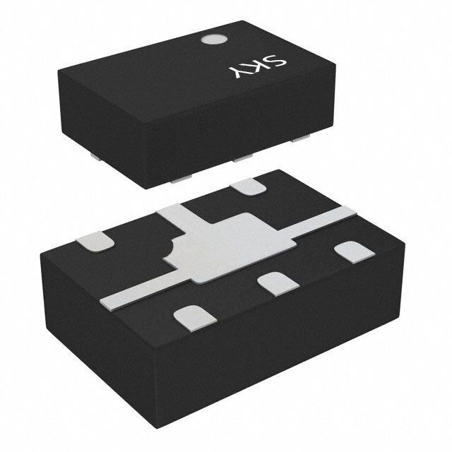
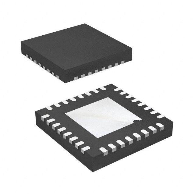
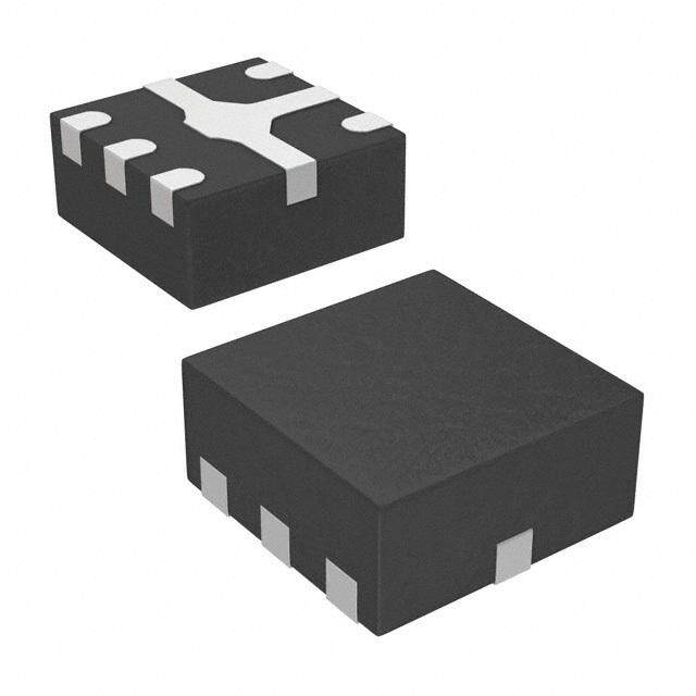
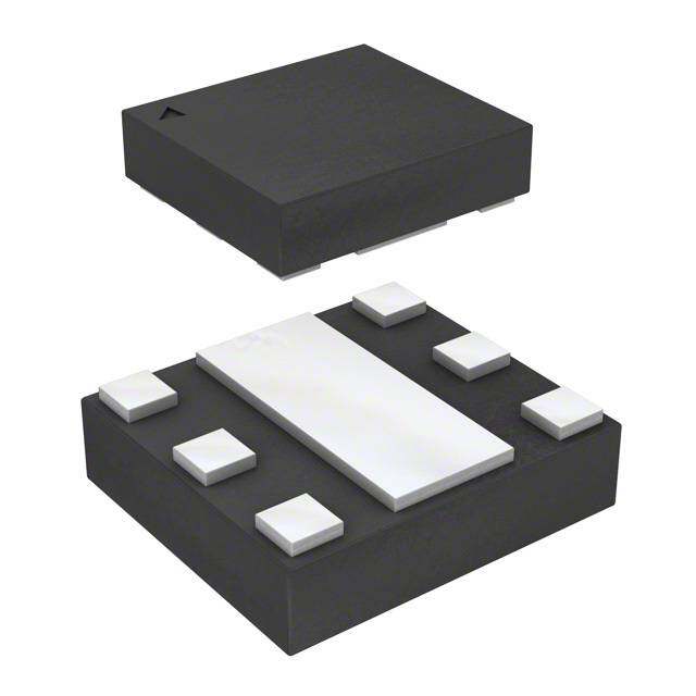
| 供应商器件封装 | 6-QFN(2x3) |
| 关闭隔离—典型值 | 20 dB |
| 其它名称 | 863-1012-2 |
| 包装 | 带卷 (TR) |
| 商标 | Skyworks Solutions, Inc. |
| 安装风格 | SMD/SMT |
| 封装 | Reel |
| 封装/外壳 | 6-VDFN 裸露焊盘 |
| 封装/箱体 | QFN-6 |
| 工作温度 | -40°C ~ 85°C |
| 工厂包装数量 | 3000 |
| 开关数量 | Single |
| 开关配置 | SPDT |
| 拓扑 | - |
| 插损@频率 | 0.6dB @ 5.85GHz |
| 最大工作温度 | + 85 C |
| 最小工作温度 | - 40 C |
| 标准包装 | 3,000 |
| 特性 | - |
| 电压-电源 | 3V,5V |
| 电路 | 单刀双掷 |
| 阻抗 | 50 欧姆 |
| 隔离@频率 | 21dB @ 5.85GHz (标准) |
| 频率 | 100 MHz to 6 GHz |
| 频率 -上 | 6GHz |
| 频率 -下 | 100MHz |
| 高控制电压 | 2.5 V to 5 V |


- 商务部:美国ITC正式对集成电路等产品启动337调查
- 曝三星4nm工艺存在良率问题 高通将骁龙8 Gen1或转产台积电
- 太阳诱电将投资9.5亿元在常州建新厂生产MLCC 预计2023年完工
- 英特尔发布欧洲新工厂建设计划 深化IDM 2.0 战略
- 台积电先进制程称霸业界 有大客户加持明年业绩稳了
- 达到5530亿美元!SIA预计今年全球半导体销售额将创下新高
- 英特尔拟将自动驾驶子公司Mobileye上市 估值或超500亿美元
- 三星加码芯片和SET,合并消费电子和移动部门,撤换高东真等 CEO
- 三星电子宣布重大人事变动 还合并消费电子和移动部门
- 海关总署:前11个月进口集成电路产品价值2.52万亿元 增长14.8%


PDF Datasheet 数据手册内容提取
DATA SHEET AS225-313LF: PHEMT GaAs IC 1 W Low-Loss 0.1 to 6 GHz SPDT Switch Applications INPUT WLAN 802.11a/b/g OUTPUT1 OUTPUT2 Features Positive low voltage control (0/3 V) Low insertion loss (0.6 dB, 0.1 to 6 GHz) High linearity (IIP3 = +53 dBm @ 3 V) 200148-001 PHEMT process VCTL1 VCTL2 Miniature QFN (6-pin, 2 x 3 mm) package Figure 1. AS225-313LF Functional Block Diagram (MSL1, 260 C per JEDEC J-STD-020) Description Skyworks GreenTM products are compliant with The AS225-313LF is a 0.1 to 6 GHz PHEMT GaAs IC single-pole, all applicable legislation and are halogen-free. double-throw (SPDT) antenna switch. Designed for WLAN For additional information, refer to Skyworks applications, this device is capable of switching 1 W microwave Definition of GreenTM, document number signals with 3 V control voltage while maintaining high-linearity SQ04–0074. performance. The switch covers the entire 802.11a, b, and g frequency ranges. The low-loss, high-isolation, high-inearity, and low-cost features make this switch ideal for Wireless LAN systems. J2 1 6 V1 Figure 1 shows the functional block diagram of the AS225-313LF. The pin configuration and package are shown in Figure 2. Signal pin assignments and functional pin descriptions are provided in Table 1. GND 2 5 J1 J3 3 4 V2 200148-002 Figure 2. AS225-313LF Pinout (Top View) Skyworks Solutions, Inc. • Phone [781] 376-3000 • Fax [781] 376-3100 • sales@skyworksinc.com • www.skyworksinc.com 200148F • Skyworks Proprietary Information • Products and Product Information are Subject to Change Without Notice • April 17, 2017 1
DATA SHEET • AS225-313LF: LOW LOSS SPDT SWITCH Table 1. SKY13290-313LF Signal Descriptions Pin Name Description Pin Name Description 1 J2 RF input/output. According to the logic voltage levels 4 V2 DC control voltage input 2. The logic voltage applied applied to the V1 and V2 pins, this port is either to this pin, along with the voltage level applied to the connected to J1 using a low insertion loss path or V1 pin, determines the states of the RF paths isolated from J1. between J1/J2 and J1/J3. 2 GND Ground. Equipotential port, internal circuit common, 5 J1 RF input/output. According to the logic voltage levels which must connected to the PCB ground or common applied to the V1 and V2 pins, this port is either using the lowest possible impedance. connected to J2 or to J3 using a low insertion loss path and isolated from the other RF port. 3 J3 RF input/output. According to the logic voltage levels 6 V1 DC control voltage input 1. The logic voltage applied applied to the V1 and V2 pins, this port is either to this pin, along with the voltage level applied to the connected to J1 using a low insertion loss path or V2 pin, determines the states of the RF paths isolated from J1. between J1/J2 and J1/J3. Electrical and Mechanical Specifications The state of the AS225-313LF is determined by the logic provided The absolute maximum ratings for the AS225-313LF are shown in in Table 5. Typical performance characteristics are shown in Table 2. Electrical specifications are provided in Tables 3 and 4. Figures 3, 4, and 5. Table 2. AS225-313LF Absolute Maximum Ratings1 Parameter Symbol Minimum Maximum Units Input power @ 0/3 V +32 dBm Input power @ 0/5 V +35 dBm Operating voltage 8 V Operating temperature TA –40 +85 C Storage temperature TSTG –65 +150 C 1 Exposure to maximum rating conditions for extended periods may reduce device reliability. There is no damage to device with only one parameter set at the limit and all other parameters set at or below their nominal value. Exceeding any of the limits listed here may result in permanent damage to the device. ESD HANDLING: Although this device is designed to be as robust as possible, electrostatic discharge (ESD) can damage this device. This device must be protected at all times from ESD when handling or transporting. Static charges may easily produce potentials of several kilovolts on the human body or equipment, which can discharge without detection. Industry-standard ESD handling precautions should be used at all times. Skyworks Solutions, Inc. • Phone [781] 376-3000 • Fax [781] 376-3100 • sales@skyworksinc.com • www.skyworksinc.com 2 April 17, 2017 • Skyworks Proprietary Information • Products and Product Information are Subject to Change Without Notice • 200148F
DATA SHEET • AS225-313LF: LOW LOSS SPDT SWITCH Table 3. AS225-313LF Electrical Specifications1 (ZO = 50 Ω, VCTRL = 0/3 V, CBLOCK = 15 pF, TA = 25 °C, Unless Otherwise Noted) Parameter Test Condition Frequency Min Typ Max Units Insertion loss J1–J2, J1–J3 0.10 to 6.00 GHz 0.60 0.75 dB 2.40 to 2.50 GHz 0.50 0.65 dB 5.15 to 5.85 GHz 0.60 0.70 dB Isolation J1–J2, J1–J3 0.10 to 6.00 GHz 18 20 dB 2.40 to 2.50 GHz 18 20 dB 5.15 to 5.85 GHz 19 21 dB Return loss J1–J2, J1–J3 0.10 to 6.00 GHz 18 20 dB 2.40 to 2.50 GHz 23 25 dB 5.15 to 5.85 GHz 21 23 dB 1 Performance is guaranteed only under the conditions listed in this table. Table 4. AS225-313LF Electrical Characteristics1 (ZO = 50 Ω, VCTRL = 0/3 V, CBLOCK = 15 pF, TA = 25 °C, Unless Otherwise Noted) Parameter Condition Frequency Min Typ Max Units Switching characteristics: Rise, fall 10/90% or 90/10% RF 20 ns On, off 50% CTL to 90/10% RF 35 ns P1dB @ 3 V 5200 MHz +30 dBm @ 5 V 5200 MHz +34 dBm 2nd harmonic PIN = +22 dBm, VC = 3 V 2450 MHz +70 dBc VC = 5 V 2450 MHz +75 dBc 3rd harmonic PIN = +22 dBm, VC = 3 V 2450 MHz +68 dBc VC = 5 V 2450 MHz +70 dBc Input IP3 Two-tone 15 dBm, 5 MHz spacing: VCTL = 0/3 V 5200 MHz +53 dBm VCTL = 0/5 V 5200 MHz +55 dBm Control voltage VC HIGH 2.5 3.00 5.00 V VC LOW –0.25 0.25 V Gate leakage VC = 3 V 10 100 μA VC = 5 V 15 200 μA 1 Performance is guaranteed only under the conditions listed in this table. Table 5. AS225-313LF Truth Table1,2 V1 V2 J1–J2 J1–J3 0 VHIGH Isolation Insertion loss VHIGH 0 Insertion loss Isolation 1 All other conditions not recommended. 2 VHIGH = 2.5 to 5 V. Skyworks Solutions, Inc. • Phone [781] 376-3000 • Fax [781] 376-3100 • sales@skyworksinc.com • www.skyworksinc.com 200148F • Skyworks Proprietary Information • Products and Product Information are Subject to Change Without Notice • April 17, 2017 3
DATA SHEET • AS225-313LF: LOW LOSS SPDT SWITCH Typical Performance Characteristics (ZO = 50 Ω, VCTRL = 0/3 V, CBLOCK = 15 pF, Unless Otherwise Noted) 0 0 J-J Path -0.2 1 2 -5 -0.4 -10 -0.6 B) Loss (dB) ---011...802 J1-J3 Path Isolation (d ---122505 JJ11--JJ23 PPaatthh -1.4 -30 ---112...680 200148-003 --3450 200148-004 0 1 2 3 4 5 6 0 1 2 3 4 5 6 Frequency (GHz) Frequency (GHz) Figure 4. Isolation vs Frequency Figure 3. Insertion Loss vs Frequency 0 -5 B) -10 d s ( -15 s o -20 L urn -25 Ret -30 J-J Path 1 3 -35 --4405 J1-J2 Path 200148-005 0 1 2 3 4 5 6 Frequency (GHz) Figure 5. Return Loss vs Frequency Skyworks Solutions, Inc. • Phone [781] 376-3000 • Fax [781] 376-3100 • sales@skyworksinc.com • www.skyworksinc.com 4 April 17, 2017 • Skyworks Proprietary Information • Products and Product Information are Subject to Change Without Notice • 200148F
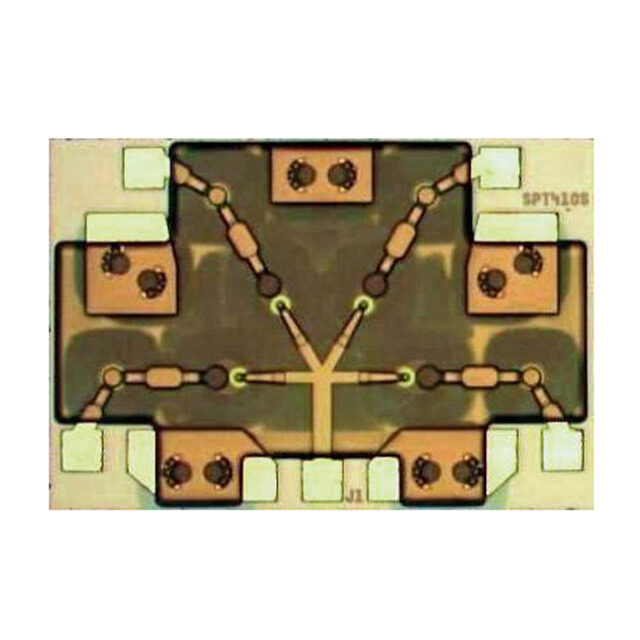
DATA SHEET • AS225-313LF: LOW LOSS SPDT SWITCH Evaluation Board and Package Dimensions Package and Handling Information The AS225-313LF Evaluation Board is used to test the Instructions on the shipping container label regarding exposure performance of the AS225-313LF SPDT switch. An Evaluation to moisture after the container seal is broken must be followed. Board schematic diagram is provided in Figure 6.An assembly Otherwise, problems related to moisture absorption may occur drawing for the Evaluation Board is shown in Figure 7. when the part is subjected to high temperature during solder assembly. The AS225-313LF is rated to Moisture Sensitivity Level 1 Package Dimensions (MSL1) at 260 C for 5 seconds. They can be used for lead or The PCB layout footprint for the AS225-313LF is shown in lead-free soldering. For additional information, refer to the Figure 8. The typical part marking is shown in Figure 9. Skyworks Application Note, Solder Reflow Information, Package dimensions are shown in Figure 10. The tape and reel document number 200164. dimensions are provided in Figure 11. Care must be taken when attaching this product, whether it is done manually or in a production solder reflow environment. Production quantities of this product are shipped in a standard tape and reel format. For additional information, refer to the Discrete Devices and IC Switch/Attenuators Tape and Reel Package Orientation Application Note. C1 RF Output 1 J2 V1 6 DC Control Voltage 2 GND J1 5 C2 RF Output C3 3 J3 V2 4 DC Control RF Output Voltage 200148-006 Note: C1, C2, C3 = 15 pF Figure 6. AS225-313LF Evaluation Board Schematic Skyworks Solutions, Inc. • Phone [781] 376-3000 • Fax [781] 376-3100 • sales@skyworksinc.com • www.skyworksinc.com 200148F • Skyworks Proprietary Information • Products and Product Information are Subject to Change Without Notice • April 17, 2017 5
DATA SHEET • AS225-313LF: LOW LOSS SPDT SWITCH 200148-007 Figure 7. AS225-313LF Evaluation Board Assembly Drawing 6X 1.150 2X 0.200 5X 0.442 Pin 1 6X 0.350 0.610 1.220 0.950 Pitch 2X 1.650 6X Exposed Soldering Area 0.230 0.840 200148-008 All dimensions are in millimeters Figure 8. AS225-313LF PCB Layout Footprint (Top View) Skyworks Solutions, Inc. • Phone [781] 376-3000 • Fax [781] 376-3100 • sales@skyworksinc.com • www.skyworksinc.com 6 April 17, 2017 • Skyworks Proprietary Information • Products and Product Information are Subject to Change Without Notice • 200148F
DATA SHEET • AS225-313LF: LOW LOSS SPDT SWITCH Skyworks Part Number Pin 1 Indicator 200148-009 Figure 9. AS225-313LF Typical Part Marking (Top View) 2X 0.05 C Pin 1 Indicator 0.841 +0.10/–0.15 2 B Seating Plane C A 0.05/0 R0.2 Detail A Pin 1 Indicator 5 0 0. – 3 0.35 ± 0.05 10/ 0. + 0.95 22 2 1. 2X 0.05 C 0.9 ± 0.1 6X 3 0.13 0.05 C 0.05 C 0.20 Top View Side View Bottom View 0.292 ± 0.075 0.35 ± 0.05 Notes: 1. All measurements are in millimeters. 5 2. Dimensions and tolerances according to ASME Y14.5M-1994. 0.10 M C A B 3. Coplanarity applies to the terminals and all other bottom surface metallization. Detail A 4. Dimension applies to metallized terminal. If the terminal has a radius on its Scale: 100X end, the width dimension should not be measured in that radius area. 5 Places 200148-010 Figure 10. AS225-313LF Package Dimensions Skyworks Solutions, Inc. • Phone [781] 376-3000 • Fax [781] 376-3100 • sales@skyworksinc.com • www.skyworksinc.com 200148F • Skyworks Proprietary Information • Products and Product Information are Subject to Change Without Notice • April 17, 2017 7
DATA SHEET • AS225-313LF: LOW LOSS SPDT SWITCH 4.00 ± 0.10 4.00 ± 0.10 2.00 ± 0.05 0.30 ± 0.05 (T) ∅1.50 +0.10/–0 1.75 ± 0.10 B Pin 1 Indicator 5 0 ± 0. 30 ± 0.10 (Bo) A A 5.50 12.00 ± 0. 0 6 3. B R0.25 Typ ∅1.50 Min 1.20 ± 0.10 (Ko) Detail B Notes: 1. Carrier tape: black conductive polystyrene, non-bakeable material. R0.3 Max 2. Cover tape material: transparent conductive HSA with 9.20 mm width. 3. ESD-surface resistivity is ≥1 x 10⁵ ~ ≤1 x 10¹⁰ Ohms/square per EIA, JEDEC TNR Specification. 2.40 ± 0.10 (Ao) 4. All measurements are in millimeters. Detail A 200148-011 Figure 11. AS225-313LF Tape and Reel Dimensions Skyworks Solutions, Inc. • Phone [781] 376-3000 • Fax [781] 376-3100 • sales@skyworksinc.com • www.skyworksinc.com 8 April 17, 2017 • Skyworks Proprietary Information • Products and Product Information are Subject to Change Without Notice • 200148F
DATA SHEET • AS225-313LF: LOW LOSS SPDT SWITCH Ordering Information Model Name Manufacturing Part Number Evaluation Board Part Number AS225-313LF SPDT Switch AS225-313LF AS225-313LF-EVB Copyright © 2002-2007, 2014, 2017 Skyworks Solutions, Inc. All Rights Reserved. Information in this document is provided in connection with Skyworks Solutions, Inc. (“Skyworks”) products or services. These materials, including the information contained herein, are provided by Skyworks as a service to its customers and may be used for informational purposes only by the customer. Skyworks assumes no responsibility for errors or omissions in these materials or the information contained herein. Skyworks may change its documentation, products, services, specifications or product descriptions at any time, without notice. Skyworks makes no commitment to update the materials or information and shall have no responsibility whatsoever for conflicts, incompatibilities, or other difficulties arising from any future changes. No license, whether express, implied, by estoppel or otherwise, is granted to any intellectual property rights by this document. Skyworks assumes no liability for any materials, products or information provided hereunder, including the sale, distribution, reproduction or use of Skyworks products, information or materials, except as may be provided in Skyworks Terms and Conditions of Sale. THE MATERIALS, PRODUCTS AND INFORMATION ARE PROVIDED “AS IS” WITHOUT WARRANTY OF ANY KIND, WHETHER EXPRESS, IMPLIED, STATUTORY, OR OTHERWISE, INCLUDING FITNESS FOR A PARTICULAR PURPOSE OR USE, MERCHANTABILITY, PERFORMANCE, QUALITY OR NON-INFRINGEMENT OF ANY INTELLECTUAL PROPERTY RIGHT; ALL SUCH WARRANTIES ARE HEREBY EXPRESSLY DISCLAIMED. SKYWORKS DOES NOT WARRANT THE ACCURACY OR COMPLETENESS OF THE INFORMATION, TEXT, GRAPHICS OR OTHER ITEMS CONTAINED WITHIN THESE MATERIALS. SKYWORKS SHALL NOT BE LIABLE FOR ANY DAMAGES, INCLUDING BUT NOT LIMITED TO ANY SPECIAL, INDIRECT, INCIDENTAL, STATUTORY, OR CONSEQUENTIAL DAMAGES, INCLUDING WITHOUT LIMITATION, LOST REVENUES OR LOST PROFITS THAT MAY RESULT FROM THE USE OF THE MATERIALS OR INFORMATION, WHETHER OR NOT THE RECIPIENT OF MATERIALS HAS BEEN ADVISED OF THE POSSIBILITY OF SUCH DAMAGE. Skyworks products are not intended for use in medical, lifesaving or life-sustaining applications, or other equipment in which the failure of the Skyworks products could lead to personal injury, death, physical or environmental damage. Skyworks customers using or selling Skyworks products for use in such applications do so at their own risk and agree to fully indemnify Skyworks for any damages resulting from such improper use or sale. Customers are responsible for their products and applications using Skyworks products, which may deviate from published specifications as a result of design defects, errors, or operation of products outside of published parameters or design specifications. Customers should include design and operating safeguards to minimize these and other risks. Skyworks assumes no liability for applications assistance, customer product design, or damage to any equipment resulting from the use of Skyworks products outside of stated published specifications or parameters. Skyworks and the Skyworks symbol are trademarks or registered trademarks of Skyworks Solutions, Inc., in the United States and other countries. Third-party brands and names are for identification purposes only, and are the property of their respective owners. Additional information, including relevant terms and conditions, posted at www.skyworksinc.com, are incorporated by reference. Skyworks Solutions, Inc. • Phone [781] 376-3000 • Fax [781] 376-3100 • sales@skyworksinc.com • www.skyworksinc.com 200148F • Skyworks Proprietary Information • Products and Product Information are Subject to Change Without Notice • April 17, 2017 9