ICGOO在线商城 > VY2150K29U2JS63V7
 Datasheet下载
- 型号: VY2150K29U2JS63V7
- 制造商: Vishay
- 库位|库存: xxxx|xxxx
- 要求:
| 数量阶梯 | 香港交货 | 国内含税 |
| +xxxx | $xxxx | ¥xxxx |
查看当月历史价格
查看今年历史价格
VY2150K29U2JS63V7产品简介:
ICGOO电子元器件商城为您提供VY2150K29U2JS63V7由Vishay设计生产,在icgoo商城现货销售,并且可以通过原厂、代理商等渠道进行代购。 提供VY2150K29U2JS63V7价格参考以及VishayVY2150K29U2JS63V7封装/规格参数等产品信息。 你可以下载VY2150K29U2JS63V7参考资料、Datasheet数据手册功能说明书, 资料中有VY2150K29U2JS63V7详细功能的应用电路图电压和使用方法及教程。
| 参数 | 数值 |
| 产品目录 | |
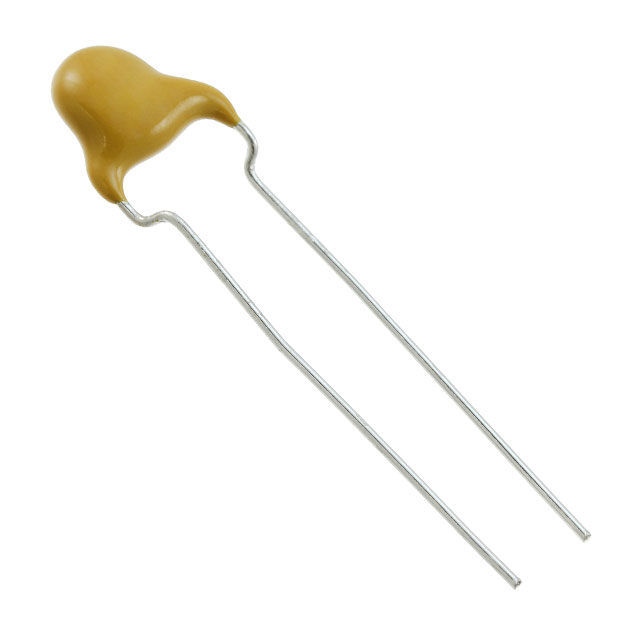
| 描述 | CAP CER 15PF 440VAC 10% RADIAL |
| 产品分类 | |
| 品牌 | Vishay BC Components |
| 数据手册 | |
| 产品图片 |
|
| 产品型号 | VY2150K29U2JS63V7 |
| rohs | 无铅 / 符合限制有害物质指令(RoHS)规范要求 |
| 产品系列 | VY2 |
| 产品培训模块 | http://www.digikey.cn/PTM/IndividualPTM.page?site=cn&lang=zhs&ptm=30367 |
| 产品目录绘图 |
|
| 产品目录页面 | |
| 其它名称 | BC2343 |
| 包装 | 散装 |
| 厚度(最大值) | - |
| 大小/尺寸 | 0.295" 直径(7.50mm) |
| 安装类型 | 通孔 |
| 容差 | ±10% |
| 封装/外壳 | 径向,圆盘 |
| 工作温度 | -40°C ~ 125°C |
| 应用 | 安全 |
| 引线形式 | 直形 |
| 引线间距 | 0.295"(7.50mm) |
| 标准包装 | 1,000 |
| 温度系数 | U2J |
| 特性 | - |
| 电压-额定 | 440VAC |
| 电容 | 15pF |
| 等级 | X1Y2 |
| 高度-安装(最大值) | 0.453"(11.50mm) |

.JPG)


- 商务部:美国ITC正式对集成电路等产品启动337调查
- 曝三星4nm工艺存在良率问题 高通将骁龙8 Gen1或转产台积电
- 太阳诱电将投资9.5亿元在常州建新厂生产MLCC 预计2023年完工
- 英特尔发布欧洲新工厂建设计划 深化IDM 2.0 战略
- 台积电先进制程称霸业界 有大客户加持明年业绩稳了
- 达到5530亿美元!SIA预计今年全球半导体销售额将创下新高
- 英特尔拟将自动驾驶子公司Mobileye上市 估值或超500亿美元
- 三星加码芯片和SET,合并消费电子和移动部门,撤换高东真等 CEO
- 三星电子宣布重大人事变动 还合并消费电子和移动部门
- 海关总署:前11个月进口集成电路产品价值2.52万亿元 增长14.8%


PDF Datasheet 数据手册内容提取
VY2 Series www.vishay.com Vishay BCcomponents AC Line Rated Ceramic Disc Capacitors Class X1, 440 V , Class Y2, 300 V AC AC FEATURES • Complying with IEC 60384-14 4th edition • High reliability • Vertical (inline) kinked or straight leads • Singlelayer AC disc safety capacitors • Material categorization: for definitions of compliance please se e www.vishay.com/doc?99912 APPLICATIONS • X1, Y2 according to IEC 60384-14.4 • Across-the-line • Line by-pass ADDITIONAL RESOURCES • Antenna coupling 3DDD 333D DESIGN 3D Models Models The capacitor consists of a ceramic disc which is silve r plated on both sides. Connection leads are made of ti n plated copper-clad steel having a diameter of 0.6 mm. QUICK REFERENCE DATA The capacitors may be supplied with vertical (inline) kinked DESCRIPTION VALUE leads having a lead spacing of 5.0 mm, 7.5 mm, 10.0 mm, or 12.5 mm. Encapsulation is made of flame retardant epoxy Ceramic Class 1 2 resin in accordance with UL 94 V-0. Ceramic Dielectric N750 Y5S, Y5U, Y5V Voltage (VAC) 300 440 300 440 CAPACITANCE RANGE Min. Capacitance (pF) 10 68 10 pF to 0.01 μF Max. Capacitance (pF) 47 10 000 RATED VOLTAGE U Mounting Radial R IEC 60384-14 and UL 60384-14: OPERATING TEMPERATURE RANGE (X1): 440 V , 50 Hz AC -40 °C to +125 °C (Y2): 300 VAC, 50 Hz 1000 V DC TEMPERATURE CHARACTERISTICS Class 1: N750 (U2J) TEST VOLTAGE Class 2: Y5S, Y5U, Y5V Component test (100 %): 2600 V , 50 Hz, 2 s AC SECTIONAL SPECIFICATIONS (2600 VAC for LS 7.5 mm and above) (2200 V for LS 5.0 mm) Climatic category (according to EN 60058-1) AC Class 1 and class 2: 40/125/21 Random sampling test (destructive test): 2600 V , 50 Hz, 60 s AC COATING Voltage proof of coating (destructive test): 2600 V , 50 Hz, 60 s According to UL 94 V-0 AC Epoxy resin, isolating, flame retardant INSULATION RESISTANCE 10 000 M APPROVALS IEC 60384-14.4 CAPACITANCE TOLERANCE UL 60384-14 ± 20 % (code M); ± 10 % (code K) DIN EN 60384-14 CSA E60384-1:03, CSA E60384-14:09 DISSIPATION FACTOR CQC11-471112 Class 1: max. 0.5 % (1 MHz) PACKAGING Class 2: max. 2.5 % (1 kHz) Bulk, tape and reel, taped ammopack Revision: 04-Sep-2019 1 Document Number: 28535 For technical questions, contact: cdc@vishay.com THIS DOCUMENT IS SUBJECT TO CHANGE WITHOUT NOTICE. THE PRODUCTS DESCRIBED HEREIN AND THIS DOCUMENT ARE SUBJECT TO SPECIFIC DISCLAIMERS, SET FORTH AT www.vishay.com/doc?91000
VY2 Series www.vishay.com Vishay BCcomponents DIMENSIONS in millimeters F e = 3.0 max. SH = 4.0 max. Ø 0.6 ± 0.05 Dmax. Tmax. L = 30.0 ± 5.0 Capacitors with 5.0 mm, 7.5 mm, 10 mm, or 12.5 mm lead spacing. Coating extension e valid for straight leads only. TECHNICAL DATA CAPACITANCE BODY BODY PART NUMBER CAPACITANCE LEAD SPACING (1) C (pF) TOLERANCE DIAMETER THICKNESS F (mm) ± 1 mm MISSING DIGITS SEE (%) Dmax. (mm) Tmax. (mm) ORDERING CODE BELOW U2J (N750) 10 VY2100K29U2JS6### 15 VY2150K29U2JS6### 22 ± 10 7.5 5.0 5.0, 7.5, 10.0, or 12.5 VY2220K29U2JS6### 33 VY2330K29U2JS6### 47 VY2470K29U2JS6### Y5S (2C3) 68 VY2680K29Y5SS6### 100 VY2101K29Y5SS6### 150 VY2151K29Y5SS6### ± 10 7.5 5.0 5.0, 7.5, 10.0, or 12.5 220 VY2221K29Y5SS6### 330 VY2331K29Y5SS6### 470 VY2471K29Y5SS6### Y5U (2E3) 680 VY2681M29Y5US6### 7.5 1000 VY2102M29Y5US6### 1500 8.0 VY2152M31Y5US6### 5.0, 7.5, 10.0, or 12.5 2200 9.0 VY2222M35Y5US6### 3300 ± 20 10.5 5.0 VY2332M41Y5US6### 3900 11.0 VY2392M43Y5US6### 4700 12.5 VY2472M49Y5US6### 6800 14.5 7.5, 10.0, or 12.5 VY2682M59Y5US63## 10 000 16.0 VY2103M63Y5US63## Y5V (2F3) MINI SIZE SERIES 1000 7.5 VY2102M29Y5VS6### 1500 7.5 VY2152M29Y5VS6### 2200 8.0 VY2222M31Y5VS6### 3300 9.0 5.0, 7.5, 10.0, VY2332M35Y5VS6### ± 20 5.0 3900 10.0 or 12.5 VY2392M39Y5VS6### 4700 10.5 VY2472M41Y5VS6### 6800 12.0 VY2682M47Y5VS6### 10 000 15.0 VY2103M59Y5VS6### Note (1) Straight leads are available on request Revision: 04-Sep-2019 2 Document Number: 28535 For technical questions, contact: cdc@vishay.com THIS DOCUMENT IS SUBJECT TO CHANGE WITHOUT NOTICE. THE PRODUCTS DESCRIBED HEREIN AND THIS DOCUMENT ARE SUBJECT TO SPECIFIC DISCLAIMERS, SET FORTH AT www.vishay.com/doc?91000
VY2 Series www.vishay.com Vishay BCcomponents ORDERING CODE ### 15th to 17th digit Lead configuration Available configurations see below Example VY2 221 K 29 Y5S S 6 U V 7 Series Capacitance Tolerance Size code Temperature Rated Lead wire Packaging / Lead Lead value code coefficient voltage diameter lead length style spacing S = 3 = bulk L = 5 = 5.0 X1/Y2 T = tape straight 7 = 7.5 300 V (AC) and reel V = inline 0 = 10.0 U = kinked X = 12.5 ammopack LEADSPACING 5.0 mm AND 7.5 mm PACKAGING PACKAGING QUANTITIES BODY DIAMETER SIZE CODE D (mm) max. BULK REEL AMMO 29 to 49 12.5 1000 1000 1000 59 to 63 16.0 500 - - LEADSPACING 10.0 mm AND 12.5 mm PACKAGING PACKAGING QUANTITIES CAPACITANCE BODY DIAMETER SIZE CODE VALUE D (mm) max. BULK REEL AMMO 10 pF to 4700 pF 29 to 49 12.5 1000 500 750 6800 pF to 0.01 μF 59 to 63 16.0 500 500 750 Note • The capacitors are supplied in bulk packaging (cardboard boxes), in tape on reel in ammopack STRAIGHT LEADS D T max. max. coating extension e 3.0 max. 30 mm to 5.0 mm (ΔR) F d = 0.6 mm Revision: 04-Sep-2019 3 Document Number: 28535 For technical questions, contact: cdc@vishay.com THIS DOCUMENT IS SUBJECT TO CHANGE WITHOUT NOTICE. THE PRODUCTS DESCRIBED HEREIN AND THIS DOCUMENT ARE SUBJECT TO SPECIFIC DISCLAIMERS, SET FORTH AT www.vishay.com/doc?91000
VY2 Series www.vishay.com Vishay BCcomponents D P P 2 ΔP ΔP Δh H 1 W 2 H0 t1 detail A t W 1 W0W A L Direction of unreeling Ø d P1 PF D0 1 0 Fig. 1 - Kinked capacitors on tape, lead spacing 5.0 mm (0.2") and 7.5 mm (0.3") P P2 T D ΔP ΔP Δh Δh F H1 Ø d t t L W2 H detail A 1 W 0 1 W W 0 L A 1 P P F D 0 1 0 Fig. 2 - Inline kink (V) leaded capacitors on tape, lead spacing 10 mm (0.40") DIMENSION OF TAPE DIMENSIONS (mm) SYMBOL PARAMETER FIG. 1 (5 mm) FIG. 1 (7.5 mm) FIG. 2 (10 mm) D (1) Body diameter 11.0 max. 14.0 max. 16.0 max. d Lead diameter 0.6 ± 0.05 0.6 ± 0.05 0.6 ± 0.05 P Pitch of component 12.7 ± 1 15.0 ± 1 25.4 ± 1 P (2) Pitch of sprocket hole 12.7 ± 0.3 15.0 ± 0.3 12.7 ± 0.3 0 P (3) Distance, hole center to lead 3.85 ± 0.7 3.75 ± 0.7 7.7 ± 1.0 1 P (3) Distance, hole to center of component 6.35 ± 1.3 7.5 ± 1.5 12.7 ± 1.5 2 F Lead spacing 5.0 (+ 0.6 / - 0.4) 7.5 (+ 0.6 / - 0.4) 10.0 (+ 0.6 / - 0.4) h Average deviation across tape ± 1.0 max. ± 1.0 max. ± 1.0 max. P Average deviation in direction of reeling ± 1.0 max. ± 1.0 max. ± 1.0 max. W Carrier tape width 18.0 + 1 / - 0.5 18.0 + 1/- 0.5 18.0 + 1 / - 0.5 W Hold-down tape width 5.0 min. 5.0 min. 5.0 min. 0 W Position of sprocket hole 9.0 + 0.75 / - 0.5 9.0 + 0.75 / - 0.5 9.0 + 0.75 / - 0.5 1 W Distance of hold-down tape 3.0 max. 3.0 max. 3.0 max. 2 H Maximum component height 32 40 40 1 H Height to seating plane (for kinked leads) 16.0 ± 0.5 16.0 ± 0.5 16.0 ± 0.5 0 H Height to seating plane (for straight leads) 20.0 ± 0.5 20.0 ± 0.5 20.0 ± 0.5 0 L Length of cut leads 11.0 max. 11.0 max. 11.0 max. L Length of lead protrusion 1.0 max. 1.0 max. 1.0 max. 1 D Diameter of sprocket hole 4.0 ± 0.2 4.0 ± 0.2 4.0 ± 0.2 0 t Total tape thickness 0.9 max. 0.9 max. 0.9 max. t Maximum thickness of tape and wires 1.5 max. 1.5 max. 1.5 max. 1 Notes (1) See “Technical Data” table (2) Cumulative pitch error: ± 1 mm/20 pitches (3) Obliquity maximum 3° Revision: 04-Sep-2019 4 Document Number: 28535 For technical questions, contact: cdc@vishay.com THIS DOCUMENT IS SUBJECT TO CHANGE WITHOUT NOTICE. THE PRODUCTS DESCRIBED HEREIN AND THIS DOCUMENT ARE SUBJECT TO SPECIFIC DISCLAIMERS, SET FORTH AT www.vishay.com/doc?91000
VY2 Series www.vishay.com Vishay BCcomponents REEL AND TAPE DATA in millimeters 51 max. 355.6 ± 2.0 330 28 ± 1.5 8.0 45 max. 360 55 Ammopack with capacitors on tape APPROVALS IEC 60384-14.4 - Safety tests This approval together with CB test certificate substitutes all national approvals. CB Certificate Y2-capacitor: CB test certificate: US-26163-UL 10 pF to 10 nF 300 V AC X1-capacitor: CB test certificate: US-26163-UL 10 pF to 10 nF 440 V AC VDE Y2-capacitor: VDE marks approval: 40009669 10 pF to 10 nF 300 V AC X1-capacitor: VDE marks approval: 40009669 10 pF to 10 nF 440 V AC DIN EN 60384-14 VDE 0565-1-1:2006-04 - Safety tests Underwriters Laboratories Inc. / Canadian Standards Association Y2-capacitor: UL-test certificate: E183844 10 pF to 10 nF 300 V AC X1-capacitor: UL-test certificate: E183844 10 pF to 10 nF 440 V AC UL 60384-14.1, CSA E60384-1:03 2nd edition, CSA E60384-14:09 2nd edition Across-the-line, antenna-coupling, and line-by-pass component CQC Y2-capacitor: CQC test certificate: CQC05001012316 10 pF to 10 nF 300 V AC X1-capacitor: CQC test certificate: CQC05001012316 10 pF to 10 nF 440 V AC Revision: 04-Sep-2019 5 Document Number: 28535 For technical questions, contact: cdc@vishay.com THIS DOCUMENT IS SUBJECT TO CHANGE WITHOUT NOTICE. THE PRODUCTS DESCRIBED HEREIN AND THIS DOCUMENT ARE SUBJECT TO SPECIFIC DISCLAIMERS, SET FORTH AT www.vishay.com/doc?91000
VY2 Series www.vishay.com Vishay BCcomponents MARKING Sample (2 sides) 10 VY2 472 M Y2 300V ~ X1 440V ~ xxxx 4 digit date code (year/week; add suffix “V” for mini size series) Front Back PERFORMANCE TEST TEST CONDITION TEST LIMITS Visual and mechanical Optical inspection, dimensions measured with caliper No visible damage, marking legible inspection Capacitance Capacitance within specified tolerance (C) 25 °C ± 3 °C, relative humidity (RH) 75 %, Dissipation 1.0 VRMS ± 0.2 VRMS at 1 kHz for Y5U and Y5S, and 1 MHz for U2J DF 0.3 % for U2J and factor (DF) DF 2.5 % for Y5S and Y5U Insulation resistance (IR) Measured within 60 s ± 5 s after charging at 500 VDC 10 000 M min. Dielectric 2600 V at 50 Hz / 60 Hz for 1 min, 50 mA max. No failure strength AC U2J: -750 ppm ± 120 ppm Temperature RH 75 %, 1.0 VRMS ± 0.2 VRMS at 1 kHz for Y5U and Y5S, Y5S: ± 22 % characteristic and 1 MHz for U2J Y5U: +22 % / -56 % Impulse 3 pulses of 5 kV No failure voltage External appearance: no visible damage C/C ± 15 % Life test 1000 h at 125 °C ± 2 °C, 550 VAC/50 Hz; DF 0.5 % for U2J and 5 % for Y5S and Y5U once every hour 1000 V for 0.1 s AC IR 3000 M Dielectric strength: no failure External appearance: no visible damage C/C ± 10 % for U2J and Humidity test 500 h at 440 VAC, 50 Hz and 500 h unloaded ± 15 % for Y5S and Y5U 40 °C, RH = 90 % to 95 % DF 0.5 % for U2J and 5 % for Y5S and Y5U IR 3000 M Dielectric strength: no failure Robustness of Pull test: 0.5 kg tensile weight in radial direction for 10 s ± 1 s No damage to capacitor body and lead wire termination Bending strength: capacitor body rotated by 90° in both directions Immersion of lead wires into 260 °C ± 5 °C solder for 10 s ± 2 s; External appearance: no visible damage Soldering min. distance from body: 1.5 mm C/C ± 5 % for U2J and ± 10 % for Y5S and Y5U effect Hand soldering at 400 °C ± 10 °C for 3 s to 4 s; Dielectric strength: no failure min. distance from body: 1.5 mm Resin (adhesive) External appearance: no visible damage Capacitance within specified tolerance Vibration test DF 0.3 % for U2J and 2.5 % for Y5S and Y5U Solder the capacitor onto test jig (glass epoxy body) and use resin IR 10 000 G (adhesive) to stick the body to the test jig. The capacitor must be soldered firmly to the supporting lead wire. Vibration change from 10 Hz to 2000 Hz and back to 10 Hz; Total amplitude: 1.5 mm; Acceleration: 100 m/s2; Sweep rate: 1 oct/min, each axis 2 h (6 h in total) Revision: 04-Sep-2019 6 Document Number: 28535 For technical questions, contact: cdc@vishay.com THIS DOCUMENT IS SUBJECT TO CHANGE WITHOUT NOTICE. THE PRODUCTS DESCRIBED HEREIN AND THIS DOCUMENT ARE SUBJECT TO SPECIFIC DISCLAIMERS, SET FORTH AT www.vishay.com/doc?91000
VY2 Series www.vishay.com Vishay BCcomponents LEAKAGE CURRENT VS. VOLTAGE (Typical) 3.5 120 60 Hz, 25 °C 100 pF 3.0 4700 pF S 100 60 Hz, 25 °C M S mA) R 2.5 33930000 ppFF A) RM 80 Leakage Current ( 0112....5050 211250640008700000 pppppFFFFF Leakage Current (μ 246000 64328732 ppppFFFF 330 pF 10 pF 220 pF 0.0 150 pF 0 0 200 400 600 800 100012001400160018002000220024002600 0 200 400 600 800 100012001400160018002000220024002600 AC Voltage (V) RMS AC Voltage (V) RMS Note • The capacitors meet the essential requirements of EIA 198. Unless stated otherwise all electrical values apply at an ambient temperature of 25 °C ± 3 °C, at normal atmospheric conditions RELATED DOCUMENTS General Information www.vishay.com/doc?28536 CB Test Certificate www.vishay.com/doc?22254 VDE Marks Approval www.vishay.com/doc?22256 UL Test Certificate www.vishay.com/doc?22253 CQC Test Certificate www.vishay.com/doc?22255 LTspice® Models www.vishay.com/doc?28568 SAMPLE KITS Part Number (VY2 Sample Kit) VY21-KIT-HF Link (VY2 Sample Kit) www.vishay.com/doc?28554 Part Number (VY2...Y5V Sample Kit) VY2-KIT-MS Link (VY2...Y5V Sample Kit) www.vishay.com/doc?28562 Revision: 04-Sep-2019 7 Document Number: 28535 For technical questions, contact: cdc@vishay.com THIS DOCUMENT IS SUBJECT TO CHANGE WITHOUT NOTICE. THE PRODUCTS DESCRIBED HEREIN AND THIS DOCUMENT ARE SUBJECT TO SPECIFIC DISCLAIMERS, SET FORTH AT www.vishay.com/doc?91000
Legal Disclaimer Notice www.vishay.com Vishay Disclaimer ALL PRODUCT, PRODUCT SPECIFICATIONS AND DATA ARE SUBJECT TO CHANGE WITHOUT NOTICE TO IMPROV E RELIABILITY, FUNCTION OR DESIGN OR OTHERWISE. Vishay Intertechnology, Inc., its affiliates, agents, and employees, and all persons acting on its or their behalf (collectively, “Vishay”), disclaim any and all liability for any errors, inaccuracies or incompleteness contained in any datasheet or in any other disclosure relating to any product. Vishay makes no warranty, representation or guarantee regarding the suitability of the products for any particular purpose o r the continuing production of any product. To the maximum extent permitted by applicable law, Vishay disclaims (i) any and all liability arising out of the application or use of any product, (ii) any and all liability, including without limitation special, consequential or incidental damages, and (iii) any and all implied warranties, including warranties of fitness for particular purpose, non-infringement and merchantability. Statements regarding the suitability of products for certain types of applications are based on Vishay’s knowledge of typical requirements that are often placed on Vishay products in generic applications. Such statements are not binding statements about the suitability of products for a particular application. It is the customer’s responsibility to validate that a particular product with the properties described in the product specification is suitable for use in a particular application. Parameters provided in datasheets and / or specifications may vary in different applications and performance may vary over time. All operating parameters, including typical parameters, must be validated for each customer application by the customer’s technical experts. Product specifications do not expand or otherwise modify Vishay’s terms and conditions of purchase, including but not limited to the warranty expressed therein. Except as expressly indicated in writing, Vishay products are not designed for use in medical, life-saving, or life-sustainin g applications or for any other application in which the failure of the Vishay product could result in personal injury or death. Customers using or selling Vishay products not expressly indicated for use in such applications do so at their own risk . Please contact authorized Vishay personnel to obtain written terms and conditions regarding products designed for such applications. No license, express or implied, by estoppel or otherwise, to any intellectual property rights is granted by this documen t or by any conduct of Vishay. Product names and markings noted herein may be trademarks of their respective owners. © 2019 VISHAY INTERTECHNOLOGY, INC. ALL RIGHTS RESERVED Revision: 01-Jan-2019 1 Document Number: 91000