ICGOO在线商城 > SP1602S01RB-PCB/NOPB

 Datasheet下载
- 型号: SP1602S01RB-PCB/NOPB
- 制造商: Texas Instruments
- 库位|库存: xxxx|xxxx
- 要求:
| 数量阶梯 | 香港交货 | 国内含税 |
| +xxxx | $xxxx | ¥xxxx |
查看当月历史价格
查看今年历史价格
SP1602S01RB-PCB/NOPB产品简介:
ICGOO电子元器件商城为您提供SP1602S01RB-PCB/NOPB由Texas Instruments设计生产,在icgoo商城现货销售,并且可以通过原厂、代理商等渠道进行代购。 提供SP1602S01RB-PCB/NOPB价格参考以及Texas InstrumentsSP1602S01RB-PCB/NOPB封装/规格参数等产品信息。 你可以下载SP1602S01RB-PCB/NOPB参考资料、Datasheet数据手册功能说明书, 资料中有SP1602S01RB-PCB/NOPB详细功能的应用电路图电压和使用方法及教程。
| 参数 | 数值 |
| 产品目录 | 编程器,开发系统 |
| 描述 | WEBENCH BARE BD BRDG DIFF-ADC |
| 产品分类 | |
| 品牌 | Texas Instruments |
| 数据手册 | http://www.ti.com/lit/pdf/snaa127 |
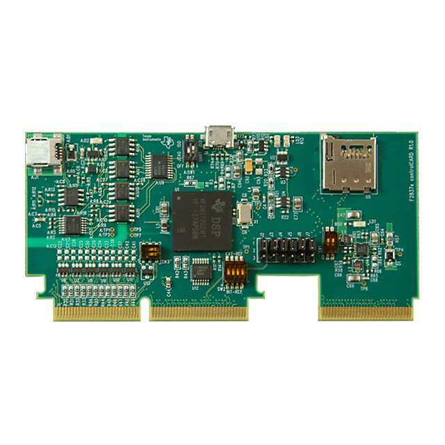
| 产品图片 |
|
| 产品型号 | SP1602S01RB-PCB/NOPB |
| rohs | 库存产品核实请求 / 库存产品核实请求 |
| 产品系列 | WEBENCH® Buildit 板 |
| 主要属性 | WEBENCH 传感器设计软件,差分式双极压力传感器放大器,差分输入 ADC |
| 主要用途 | 接口,传感器至模数转换器接口,差分传感器 |
| 使用的IC/零件 | 10-MSOP 封装 |
| 其它名称 | 551600261-001 |
| 嵌入式 | 否 |
| 所含物品 | 裸板 |
| 标准包装 | 1 |
| 辅助属性 | - |


- 商务部:美国ITC正式对集成电路等产品启动337调查
- 曝三星4nm工艺存在良率问题 高通将骁龙8 Gen1或转产台积电
- 太阳诱电将投资9.5亿元在常州建新厂生产MLCC 预计2023年完工
- 英特尔发布欧洲新工厂建设计划 深化IDM 2.0 战略
- 台积电先进制程称霸业界 有大客户加持明年业绩稳了
- 达到5530亿美元!SIA预计今年全球半导体销售额将创下新高
- 英特尔拟将自动驾驶子公司Mobileye上市 估值或超500亿美元
- 三星加码芯片和SET,合并消费电子和移动部门,撤换高东真等 CEO
- 三星电子宣布重大人事变动 还合并消费电子和移动部门
- 海关总署:前11个月进口集成电路产品价值2.52万亿元 增长14.8%


PDF Datasheet 数据手册内容提取
ADC121S101,ADC161S626 Liquid-Level Monitoring Using a Pressure Sensor Literature Number: SNAA127
SIGNAL PATH designer® Tips, tricks, and techniques from the analog signal-path experts No. 115 Liquid-Level Monitoring Using Feature Article ...............1-4 a Pressure Sensor Design Made Easy .............5 — By Amy Le, Applications Engineer L iquid-level monitoring plays an important role in today’s automotive, oil, water, pressure, and gas industries, to name a few. For example, pumping oil into a storage tank requires liquid-level monitoring to prevent spillage. Draining liquid out of a silo into bottles also requires liquid- level monitoring for volume control. Th is article will explain how to automate a liquid monitoring system using a pressure sensor. Since obtaining the pressure is just one vital piece of the information, how to convert the sensor’s output voltage into the liquid’s height using an analog-to-digital converter (ADC) will also be explained. Details of the pressure sensor, ADC connections, system calibration and calculations, as well as an example application, are available to guide designers through the development phase. Pressure Sensor Level-Sensing Theory Th e height of liquid in a container can be measured using a e pressure sensor. Placed at the top of the container, the pressure b u T sensor is connected to an open-ended tube that is submerged n in the container. Th e amount of water in the container exerts ebuT i riA d e a proportional amount of pressure on the sensor via the trapped p p a air in the tube. At its output, the sensor produces a pressure- rT equivalent voltage. re Essentially, the pressure sensor is a Wheatstone Bridge nia tn (Figure 1). Changes to the pressure on the bridge are analogous o C to the changes in the value of the bridge’s resistors, R. reniatn ni diuq VBR oC iL eh R t fo R th g ie H VSENSE+ VSENSE- R R Figure 2. Container Figure 1. Bridge Sensor
SIGNAL PATH designer Liquid-Level Monitoring Using a Pressure Sensor Hardware Both confi gurations contain the gain stage to amplify Pressure Sensor the millivolts sensor output to the reasonable 0V to Th e diff erential sensor used in the example applica- 4.1V ADC operating range. Th e output code of the tion is GE NovaSensor’s NPC-1210 series. Th e ADC is read by a microcontroller via SPI and is up- NPC-1210 has a typical Full Scale Output (FSO) of loaded to a PC to be analyzed. An example block 50 mV for 10 inches of water. Th at is, 10 inches diagram of the diff erential to single-ended signal of water in the container corresponds to a typical path can be seen in Figure 3. sensor’s diff erential output voltage of 50 mV. Th is linear relationship is useful information for calcu- laaptpinrgo prtihaete AliqDuCid ’as ndh eaimghptl ifia enrd f ord ethteer msyisnteinmg. the Pressure PSreesnssuorre VVSSEENNSSEE-+ +- VVOUINT__AADMCP ADC121S101 DOUT Instrumentation Th is particular sensor was selected due to its low Amplifier sensitivity characteristic, which means its output Figure 3. SP1202S01RB Sensor will be in the millivolts range. Since the example Reference Board Block Diagram application has a small amount of liquid volume (approximately 540 inches3), a sensitive pressure Pressure Sensor Calibration sensor is adequate. It is important to select the pres- Finding the linear relationship between the sensor’s sure sensor appropriate for a given application. output voltage and height of the liquid requires National Semiconductor’s Sensor WEBENCH® calibrating the particular system. Th e NPC-1210 online design tool (national.com/appinfo/webench/ sensor datasheet states that a typical relationship is sensorpath.html) can help customers in choosing 50 mV to 10 inches of liquid. By pouring in the con- the appropriate sensor based on input range and tainer ‘x’ inches of liquid and then measuring the desired accuracy. sensor’s diff erential output voltage ‘∆y’, where ∆y is [(Vsense+ ) - (Vsense- )], the sensor can be calibrated. Sensor Reference Board National’s newest sensor reference boards (Order ∆V = (V ) – (V ) SENSOR_OUT SENSE + SENSE- ( 1 ) No: SP1202S01RB and SP1602S02RB) are ideal sensor interface developments for liquid-level moni- ∆V = ( ∆y( x (Height) ( 2 ) SENSOR_OUT x toring systems. Th e SP1202S01RB sensor reference board has a diff erential to single-ended confi guration using an instrumentation amplifi er connected to a Th is linear relationship can be used to fi nd the single-ended, 12-bit, single-channel ADC121S101 sensor’s diff erential output voltage, ∆V , at SENSOR_OUT converter. Th e latter board also has an instrumenta- a new height as seen in Equation 2. tion amplifi er but uses a diff erential, 16-bit, single- The Liquid’s Height Calculation channel ADC161S626 device in a single-ended As shown in Figure 3, the liquid-level monitoring fashion. signal path has three stages. For that reason, calcu- Both boards serve the similar function of amplifying lating the liquid’s height in terms of the ADC and the sensor’s output voltage and converting it to an amplifi er requires several processes. Th e fi rst step is output code. However, because the resolution for the fi nding the gain of the amplifi er and multiplying SP1602S02RB sensor reference board is higher due this gain with the sensor’s output voltage, to the 16-bit ADC, it is more sensitive to changes ∆V , to obtain the ADC input voltage, SENSOR_OUT in the liquid’s level than the SP1202S01RB sensor V . IN_ADC reference board. V = V = (∆V ) x (Gain) ( 3 ) IN_ADC OUT_AMP SENSOR_OUT 2
SIGNAL PATH designer Finding the gain of any amplifi er stage can be D = (VIN_ADC (x (2n) ( 5a ) OUT_DIFF 2 x V cumbersome. For simplifi cation, an example calcu- REF lation for the instrumentation amplifi er (Figure 4) (V ( used in the example application can be seen in a D = IN_ADC x (2n) ( 5b ) OUT_SE V series of equations (4a – 4e). Th ese calculations use REF superposition and simple op amp equations to Finally, the output code is converted to the liquid’s derive the ADC input, V , and gain of the IN_ADC height using Equation 6a for a diff erential ADC or instrumentation amplifi er stage. To obtain a good 6b for a single-ended ADC. Th ese equations are common-mode rejection, RF should be equal to 1 derived from Equation 2 but diff er from Equation 2 RF ; RA should be equal to RA ; and RB should 2 1 2 1 because ∆V is now written in terms of the be equal to RB . SENSOR_OUT 2 ADC and amplifi er gain. RB1 [ x [ ( 1 ( [(D ) x (2 x V )[ VSENSE + + V1 HeightDIFF = ∆y x Gain x OUT_DIF(F2n) REF ( 6a ) - RA1 RG1 RRFF21 V2 RA2 +- =V OVUITN__AAMDPC HeightSE = [ ∆xy[x(Ga1in(x[(DOUT_S(E2)n )x (VREF)[ ( 6b ) V X Example Application - + RB2 An example application is illustrated in Figure 7 in V SENSE - which a container full of water is measured using the NPC-1210 pressure sensor. Water is continu- Figure 4. Instrumentation Amplifi er ously drained out of the container into an external water tub that contains an electrical pump. When ( RF ( (-RF ( the water level is low, the electrical pump turns on V =(V )× 1+ 1 +(V )× 1 ( 4a ) 1 SENSE+ RG SENSE- RG and pumps water back into the tube. When the water 1 1 level reaches a predetermined point near the top, the (-RF ( ( RF ( V =(V )× 2 +(V )× 1+ 2 ( 4b ) pump turns off and awaits the lower trip point to 2 SENSE+ RG SENSE- RG 1 1 turn on again as water is drained out of the tube. Th is cycle repeats until the power is turned off . ( RB ( V = 2 ×(V ) ( 4c ) X RB2 + RA2 2 To create this continuous fl uctuation of water level, a comparator with hysteresis (Figure 5), an inverter, [RB + RA [ ( RB ( V =V =V × 1 1 -V × 1 ( 4d ) and a relay switch are added to the previously men- IN_ADC OUT_AMP X RA 1 RA 1 1 tioned hardware connections. Th e ADC’s input is V compared to the reference voltage of the comparator, Gain = IN_ADC ( 4e ) ∆V V (not to be confused with the reference SENSOR_OUT REF_COMP voltage of the ADC). If V is greater than IN_ADC Next, simple diff erential (DIFF) and single-ended R2 (SE) ADC formulas can be used to fi nd the ADC cohuotpseunt bcaosdeed, oDnO tUhTe. tThy pee oafp pArDopCri autsee de qinu aat ioginv eins VIN_ADC R1 + VOUT_COMP system. In both confi gurations, V is the ADC VREF_COMP - REF reference voltage and n is the ADC-bit resolution. Figure 5. Comparator with Hysteresis signalpath.national.com/designer 3
SIGNAL PATH designer Liquid-Level Monitoring Using a Pressure Sensor Th e comparator’s output is connected to two powered FETs acting as a buff er. Although the inverter is not necessary, the FETs’ main purpose is providing suffi cient current to turn on the relay. P M CO Pump Pump Having one pin connected to AC power and the UT_ On Off other unconnected, the relay switches between a O V pump-to-power connection and a pump-to-ground connection. Th e application is a good demonstration for liquid- 0 V V V IN1 IN_ADC IN 2 level monitoring systems that require a safety Figure 6. Hysteresis mechanism. Without depending on software, this hardware connection can turn off the pump when V , then the comparator’s output is high; REF_COMP the water approaches the overfl ow point. Th e ex- otherwise, it’s low. As shown in Figure 6, hysteresis ample application also illustrates the usefulness of is added to the comparator to create two switching the sensor reference board. Its complete signal path thresholds at V and V . Th ese switching thresh- IN1 IN2 design makes enhancing any sensor applications olds represent the positions when the pump turns signifi cantly more convenient. on and off . Conclusion Equations 7a and 7b show how these thresholds can Liquid-level monitoring systems require the use of be easily adjusted by changing the comparator’s resis- pressure sensors to measure the pressure, and thus tors R and R . It is up to the designer to pick a com- 1 2 the height, of the liquid. Since the sensor’s output fortable reference voltage, V , and available REF_COMP voltage is meaningless to the average users, an ADC resistor values to get the desired threshold voltages. is needed to convert the analog voltage to a digital language in which a computer’s software can math- [(V ) (R + R )] - [V R ] ematically compute the height of the liquid. Th is V = REF_COMP 1 2 CC 1 (7a) IN1 R signal path design is encapsulated in National’s 2 sensor reference boards. As illustrated in the example application, the SP1202S01RB sensor reference [(V ) x (R +R )] V = REF_COMP 1 2 (7b) board is ideal for many pressure-sensor applications. IN2 R 2 Pressure Sensor SP1202S01RB Sensor Reference Board Instrumentation VREF VA VSENSE+ + Amplifier - ADC121S101 Microcontroller ` VSENSE- 5V 5V Liquid Monitoring Board 10 kOhm 10 kOhm R2 Pump R1 + BS270 VREF_COMP - AC Line LMV762 Unconnected Relay Tub of Water Figure 7. Liquid Monitoring System 4
marks. All rights reserved. tradeWise are registered Ddeisscigonv erre sao wurecaelsth of Fpirnodd uthcets p feorrf eyocut rm dixe soifg n Dvaelsidigante, bau silodl uatniodn © 2008, National Semiconductor Corporation. National Semiconductor, , and Power Eoatexnncpldihnl otnehro eecl o o“laghutioreeswsse.t s td,o ea”sr vitgiicdnle eoss, , Uccspiaorstoetleladas lNu totecoagrt t,asc idol.o,o nmawanpl’ndsal rofoeean adaltiannubedrel epsde r oolednculitnc et StDWhpeeEes BniegEednNw etiC rmW Haen E-PdtBoo Ee-wmNnehCarar HDkn®eec tSse wideg nintsheo r.r national.com/easy
Design Tools WEBENCH® Signal Path Designer® Tools Design, simulate, and optimize amplifi er circuits in this FREE online design and prototyping environment allowing you to: ■ Synthesize an anti-alias fi lter ■ Select the best amplifi er/ADC combo for your system specs ■ Make trade-offs based on SNR, SFDR, supply voltage ■ Simulate real-world operating conditions using SPICE ■ Receive samples in 24 hours webench.national.com WaveVision 4.1 Evaluation Board Test and evaluate A/D converters with National’s easy-to use WaveVision 4.1 evaluation board. Each evaluation board comes complete with USB cable and support software. Features and benefi ts: • Plug-n-play ADC evaluation board • USB 2.0 interface to PC • PC-based data capture • Easy data capture and evaluation • Highlighted harmonic and SFDR frequencies • Easy waveform examination • Produces and displays FFT plots • Dynamic performance parameter readout with FFT • Produces and displays histograms National Semiconductor 2900 Semiconductor Drive Santa Clara, CA 95051 1 800 272 9959 Don’t miss a single issue! Mailing address: PO Box 58090 Santa Clara, CA 95052 Subscribe now to receive email alertss when new issues of Signal Path Designer® are available: Visit our website at: www.national.com signalpath.national.com/designer For more information, send email to: Also, be sure to check out our new.feedback@nsc.com Power Designer! View online today att:: power.national.com/designer ©2008, National Semiconductor Corporation. National Semiconductor, , WEBENCH, and Signal Path Designer are registered trademarks of National Semiconductor. All other brand or product names are trademarks or registered trademarks of their respective holders. All rights reserved. 550263-019
IMPORTANTNOTICE TexasInstrumentsIncorporatedanditssubsidiaries(TI)reservetherighttomakecorrections,modifications,enhancements,improvements, andotherchangestoitsproductsandservicesatanytimeandtodiscontinueanyproductorservicewithoutnotice.Customersshould obtainthelatestrelevantinformationbeforeplacingordersandshouldverifythatsuchinformationiscurrentandcomplete.Allproductsare soldsubjecttoTI’stermsandconditionsofsalesuppliedatthetimeoforderacknowledgment. TIwarrantsperformanceofitshardwareproductstothespecificationsapplicableatthetimeofsaleinaccordancewithTI’sstandard warranty.TestingandotherqualitycontroltechniquesareusedtotheextentTIdeemsnecessarytosupportthiswarranty.Exceptwhere mandatedbygovernmentrequirements,testingofallparametersofeachproductisnotnecessarilyperformed. TIassumesnoliabilityforapplicationsassistanceorcustomerproductdesign.Customersareresponsiblefortheirproductsand applicationsusingTIcomponents.Tominimizetherisksassociatedwithcustomerproductsandapplications,customersshouldprovide adequatedesignandoperatingsafeguards. TIdoesnotwarrantorrepresentthatanylicense,eitherexpressorimplied,isgrantedunderanyTIpatentright,copyright,maskworkright, orotherTIintellectualpropertyrightrelatingtoanycombination,machine,orprocessinwhichTIproductsorservicesareused.Information publishedbyTIregardingthird-partyproductsorservicesdoesnotconstitutealicensefromTItousesuchproductsorservicesora warrantyorendorsementthereof.Useofsuchinformationmayrequirealicensefromathirdpartyunderthepatentsorotherintellectual propertyofthethirdparty,oralicensefromTIunderthepatentsorotherintellectualpropertyofTI. ReproductionofTIinformationinTIdatabooksordatasheetsispermissibleonlyifreproductioniswithoutalterationandisaccompanied byallassociatedwarranties,conditions,limitations,andnotices.Reproductionofthisinformationwithalterationisanunfairanddeceptive businesspractice.TIisnotresponsibleorliableforsuchaltereddocumentation.Informationofthirdpartiesmaybesubjecttoadditional restrictions. ResaleofTIproductsorserviceswithstatementsdifferentfromorbeyondtheparametersstatedbyTIforthatproductorservicevoidsall expressandanyimpliedwarrantiesfortheassociatedTIproductorserviceandisanunfairanddeceptivebusinesspractice.TIisnot responsibleorliableforanysuchstatements. TIproductsarenotauthorizedforuseinsafety-criticalapplications(suchaslifesupport)whereafailureoftheTIproductwouldreasonably beexpectedtocauseseverepersonalinjuryordeath,unlessofficersofthepartieshaveexecutedanagreementspecificallygoverning suchuse.Buyersrepresentthattheyhaveallnecessaryexpertiseinthesafetyandregulatoryramificationsoftheirapplications,and acknowledgeandagreethattheyaresolelyresponsibleforalllegal,regulatoryandsafety-relatedrequirementsconcerningtheirproducts andanyuseofTIproductsinsuchsafety-criticalapplications,notwithstandinganyapplications-relatedinformationorsupportthatmaybe providedbyTI.Further,BuyersmustfullyindemnifyTIanditsrepresentativesagainstanydamagesarisingoutoftheuseofTIproductsin suchsafety-criticalapplications. TIproductsareneitherdesignednorintendedforuseinmilitary/aerospaceapplicationsorenvironmentsunlesstheTIproductsare specificallydesignatedbyTIasmilitary-gradeor"enhancedplastic."OnlyproductsdesignatedbyTIasmilitary-grademeetmilitary specifications.BuyersacknowledgeandagreethatanysuchuseofTIproductswhichTIhasnotdesignatedasmilitary-gradeissolelyat theBuyer'srisk,andthattheyaresolelyresponsibleforcompliancewithalllegalandregulatoryrequirementsinconnectionwithsuchuse. TIproductsareneitherdesignednorintendedforuseinautomotiveapplicationsorenvironmentsunlessthespecificTIproductsare designatedbyTIascompliantwithISO/TS16949requirements.Buyersacknowledgeandagreethat,iftheyuseanynon-designated productsinautomotiveapplications,TIwillnotberesponsibleforanyfailuretomeetsuchrequirements. FollowingareURLswhereyoucanobtaininformationonotherTexasInstrumentsproductsandapplicationsolutions: Products Applications Audio www.ti.com/audio CommunicationsandTelecom www.ti.com/communications Amplifiers amplifier.ti.com ComputersandPeripherals www.ti.com/computers DataConverters dataconverter.ti.com ConsumerElectronics www.ti.com/consumer-apps DLP®Products www.dlp.com EnergyandLighting www.ti.com/energy DSP dsp.ti.com Industrial www.ti.com/industrial ClocksandTimers www.ti.com/clocks Medical www.ti.com/medical Interface interface.ti.com Security www.ti.com/security Logic logic.ti.com Space,AvionicsandDefense www.ti.com/space-avionics-defense PowerMgmt power.ti.com TransportationandAutomotive www.ti.com/automotive Microcontrollers microcontroller.ti.com VideoandImaging www.ti.com/video RFID www.ti-rfid.com OMAPMobileProcessors www.ti.com/omap WirelessConnectivity www.ti.com/wirelessconnectivity TIE2ECommunityHomePage e2e.ti.com MailingAddress:TexasInstruments,PostOfficeBox655303,Dallas,Texas75265 Copyright©2011,TexasInstrumentsIncorporated