ICGOO在线商城 > 射频/IF 和 RFID > RF 放大器 > SKY65009-70LF
 Datasheet下载
- 型号: SKY65009-70LF
- 制造商: SKYWORKS
- 库位|库存: xxxx|xxxx
- 要求:
| 数量阶梯 | 香港交货 | 国内含税 |
| +xxxx | $xxxx | ¥xxxx |
查看当月历史价格
查看今年历史价格
SKY65009-70LF产品简介:
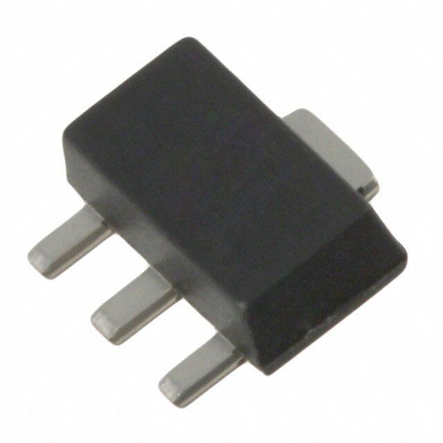
ICGOO电子元器件商城为您提供SKY65009-70LF由SKYWORKS设计生产,在icgoo商城现货销售,并且可以通过原厂、代理商等渠道进行代购。 SKY65009-70LF价格参考¥38.36-¥38.36。SKYWORKSSKY65009-70LF封装/规格:RF 放大器, 射频放大器 IC GSM,ISM,PCS,WCDMA 250MHz ~ 2.5GHz SOT-89-3。您可以下载SKY65009-70LF参考资料、Datasheet数据手册功能说明书,资料中有SKY65009-70LF 详细功能的应用电路图电压和使用方法及教程。
Skyworks Solutions Inc. 的型号 SKY65009-70LF 是一款 RF(射频)放大器,具体属于低噪声放大器(LNA, Low Noise Amplifier)类别。其主要应用场景包括以下领域:

 1. 无线通信设备
   - 蜂窝网络终端:适用于2G、3G和4G LTE设备,例如智能手机、平板电脑和移动热点。该放大器可以增强信号接收能力,提升通信质量。
   - 物联网(IoT)设备:用于低功耗广域网(LPWAN)设备,如传感器、智能仪表和可穿戴设备,确保在弱信号环境下的稳定连接。

 2. 卫星通信
   - 卫星接收终端:在卫星通信系统中,SKY65009-70LF 可用于接收微弱的下行信号,提高系统的灵敏度。
   - GPS 和 GNSS 模块:增强导航信号的接收性能,特别是在城市峡谷或遮挡环境中。

 3. Wi-Fi 和 Zigbee 系统
   - 路由器和接入点:在 Wi-Fi 设备中,该放大器可用于增强信号覆盖范围,改善网络性能。
   - 智能家居设备:支持 Zigbee 或其他短距离无线协议的设备,提升数据传输的可靠性和距离。

 4. 工业与医疗应用
   - 工业无线传感器网络:在工厂自动化或远程监控系统中,用于信号放大以克服复杂的电磁环境。
   - 医疗设备:如无线健康监测设备,确保患者数据的准确传输。

 5. 军事与航空航天
   - 军用通信设备:在需要高可靠性、低噪声的军事通信系统中,该放大器能够提供优异的性能。
   - 无人机和卫星链路:用于小型化、轻量化的无人机通信模块,确保长距离数据传输。

 特性总结
SKY65009-70LF 具有低噪声系数、高增益和宽带频率范围(约 700 MHz 至 2.7 GHz),使其非常适合需要高性能射频信号放大的应用场景。此外,其紧凑的封装形式(SOT-553)也便于集成到小型化设备中。
| 参数 | 数值 |
| 产品目录 | |
| 描述 | IC AMP DVR 250-2500MHZ SOT89-3 |
| 产品分类 | |
| 品牌 | Skyworks Solutions Inc |
| 数据手册 | |
| 产品图片 |
|
| P1dB | 25dBm(316.2mW) |
| 产品型号 | SKY65009-70LF |
| RF类型 | GSM,ISM,PCS,WCDMA |
| rohs | 无铅 / 符合限制有害物质指令(RoHS)规范要求 |
| 产品系列 | - |
| 产品目录绘图 |
|
| 产品目录页面 | |
| 供应商器件封装 | SOT-89-3 |
| 其它名称 | 863-1060-1 |
| 包装 | 剪切带 (CT) |
| 噪声系数 | 6.5dB |
| 增益 | 22dB |
| 封装/外壳 | TO-243AA |
| 标准包装 | 1 |
| 测试频率 | 450MHz |
| 特色产品 | http://www.digikey.com/cn/zh/ph/skyworks/sky65009.html |
| 电压-电源 | 3.3V,5V |
| 电流-电源 | 100mA |
| 频率 | 250MHz ~ 2.5GHz |


- 商务部:美国ITC正式对集成电路等产品启动337调查
- 曝三星4nm工艺存在良率问题 高通将骁龙8 Gen1或转产台积电
- 太阳诱电将投资9.5亿元在常州建新厂生产MLCC 预计2023年完工
- 英特尔发布欧洲新工厂建设计划 深化IDM 2.0 战略
- 台积电先进制程称霸业界 有大客户加持明年业绩稳了
- 达到5530亿美元!SIA预计今年全球半导体销售额将创下新高
- 英特尔拟将自动驾驶子公司Mobileye上市 估值或超500亿美元
- 三星加码芯片和SET,合并消费电子和移动部门,撤换高东真等 CEO
- 三星电子宣布重大人事变动 还合并消费电子和移动部门
- 海关总署:前11个月进口集成电路产品价值2.52万亿元 增长14.8%


PDF Datasheet 数据手册内容提取
DATA SHEET SKY65009-70LF: 250 to 2500 MHz Linear Power Amplifier Driver Applications Description UHF television, CATV, DBS Skyworks SKY65009-70LF is a high-performance, ultra-wideband power amplifier (PA) driver with superior output power, noise TETRA radio figure, linearity, and efficiency. The high linearity and superior GSM, GPRS, CDMA, WCDMA adjacent channel power rejection/adjacent channel leakage ratio AMPS, PCS,DCS (ACPR/ACLR) performance make the SKY65009-LF ideal for use in the driver stage of infrastructure transmit chains. ISM band transmitters The SKY65045-70LF is fabricated with Skyworks high-reliability Fixed WCS Aluminum (Al) Gallium Arsenide (GaAs) Heterojunction Bipolar WLAN, WiMAX Transistor (HBT) process, which allows for single-supply operation RFID while maintaining high efficency and good linearity. The device uses low-cost surface-mount technology (SMT) in the form of a 2.4 x 4.5 mm small outline transistor (SOT-89) package. Features The module can operate over a temperature range of –40 °C to Wideband frequency range: 250 to 2500 MHz +85 °C. A populated Evaluation Board is available upon request. High linearity OIP3: +40 dBm A functional block diagram is provided in Figure 1. Output P1 dB > +25 dBm High efficiency: PAE 40% GND Single DC supply: 3.3 V or 5 V 4 On-chip bias circuit Low power consumption SOT-89 (4-pin 2.4 x 4.5 mm) Pb-free, R0HS-compliant package (MSL1, 260 C per JEDEC J-STD-0-20) Skyworks GreenTM products are compliant with 1 2 3 all applicable legislation and are halogen-free. RF_IN GND RF_OUT For additional information, refer to Skyworks Definition of GreenTM, document number SKY65009s244 SQ04–0074. Figure 1. SKY65009-70LF Functional Block Diagram Skyworks Solutions, Inc. Phone [781] 376-3000 • Fax [781] 376-3100 sales@skyworksinc.com www.skyworksinc.com 200953F Skyworks Proprietary Information Products and Product Information are Subject to Change Without Notice August 8, 2017 1
DATA SHEET SKY65009-70LF: LINEAR PA DRIVER Technical Description Electrical and Mechanical Specifications The SKY65009-70LF is a single-stage, wideband PA in a low-cost Signal pin assignments and functional pin descriptions for the surface-mount package. The device operates with a single 3 V or SKY65009 are provided in Table 1. The absolute maximum 5 V power supply connected though an RF choke (L1) to the ratings are provided in Table 2, and the recommended operating output pin. Capacitors C7, C8, and C9 provide DC bias decoupling conditions in Table 3. Electrical characteristics for the SKY65009 for VCC. are provided in Table 4. The bias current is set by the on-chip active bias composed of Typical performance characteristics of the SKY65009 are illustrated in Figures 2 through 92. current mirror and reference voltage transistors, allowing for excellent gain tracking over temperature and voltage variations. The part is externally RF matched using surface mount Package and Handling Information components to facilitate operation over a frequency range of Instructions on the shipping container label regarding exposure to 250 MHz to 2500 MHz. moisture after the container seal is broken must be followed. Pin 1 is the RF input and pin 3 is the RF output. External DC Otherwise, problems related to moisture absorption may occur blocking is required for both input and output, but can be when the part is subjected to high temperature during solder implemented as part of the RF matching circuit. Pin 2 and the assembly. package backside metal, pin 4, provide the DC and RF ground. The SKY65009 is rated to Moisture Sensitivity Level 1 (MSL1) at 260 C. It can be used for lead or lead-free soldering. For additional information, refer to the Skyworks Application Note, Solder Reflow Information, document number 200164. Care must be taken when attaching this product, whether it is done manually or in a production solder reflow environment. Production quantities of this product are shipped in a standard tape and reel format. Table 1. SKY65009 Signal Descriptions1 Pin Name Description 1 RF_IN RF input 2 GND Ground 3 RF_OUT RF output/VCC 4 GND Center ground 1 Center attachment pad must have low inductance and low thermal resistance connections to the customer’s printed circuit board ground plane. Skyworks Solutions, Inc. Phone [781] 376-3000 Fax [781] 376-3100 sales@skyworksinc.com www.skyworksinc.com 2 August 8, 2017 Skyworks Proprietary Information Products and Product Information are Subject to Change Without Notice 200953F
DATA SHEET SKY65009-70LF: LINEAR PA DRIVER Table 2. SKY65009 Absolute Maximum Ratings (TA = +25 C, Unless Otherwise Noted) 1 Parameter Symbol Value Units RF output power POUT +26 dBm Supply voltage VCC 6 V Supply current ICC 300 mA Power dissipation PD 1.1 W Operating case temperature range TC -40 to +85 °C Storage temperature range TST -55 to +125 °C Junction temperature TJ 150 °C 1 Performance is guaranteed only under the conditions listed in the specifications table and is not guaranteed under the full range(s) described by the Absolute Maximum specifications. Exceeding any of the absolute maximum/minimum specifications may result in permanent damage to the device and will void the warranty. ESD HANDLING: Although this device is designed to be as robust as possible, electrostatic discharge (ESD) can damage this device. This device must be protected at all times from ESD when handling or transporting. Static charges may easily produce potentials of several kilovolts on the human body or equipment, which can discharge without detection. Industry-standard ESD handling precautions should be used at all times. Table 3. SKY65009 Recommended Operating Conditions Parameter Symbol Min Typical Max Units Supply voltage VCC 5 5.5 V Operating frequency fO 100 2500 MHz Operating case temperature TC –40 +25 +85 °C Thermal resistance (junction to case) θJC 20 °C/W Table 4. SKY65009 Electrical Characteristics1 (1 of 3) (VCC = 5.0 V, Output Impedance = 50 Ω, TC = 25 °C, Unless Otherwise Noted) Parameter Symbol Test Conditions Min Typical Max Units Test Frequency = 450 MHz Frequency f 450 MHz Small signal gain S21 PIN = –15 dBm 22 dB Input return loss S11 Small signal 14.5 dB Output return loss S22 Small signal 11.5 dB 1 dB output compression point OP1db CW +26.8 dBm Power-added efficiency PAE @ P1dB 38.5 % Third order output intercept point OIP3 PIN/tone = 0 dBm, +35 dBm Δf = 1 MHz Noise figure NF PIN = –15 dBm 6.5 dB Quiescent current ICCQ No RF 100 mA Skyworks Solutions, Inc. Phone [781] 376-3000 • Fax [781] 376-3100 sales@skyworksinc.com www.skyworksinc.com 200953F Skyworks Proprietary Information Products and Product Information are Subject to Change Without Notice August 8, 2017 3
DATA SHEET SKY65009-70LF: LINEAR PA DRIVER Table 4. SKY65009 Electrical Characteristics1 (2 of 3) (VCC = 5.0 V, Output Impedance = 50 Ω, TC = 25 °C, Unless Otherwise Noted) Parameter Symbol Test Conditions Min Typical Max Units Test Frequency = 900 MHz Frequency f 900 MHz Small signal gain S21 PIN = –15 dBm 17 dB Input return loss S11 Small signal 9 dB Output return loss S22 Small signal 7.5 dB 1 dB output compression point P1db CW +25.0 dBm Power-added efficiency PAE @ P1dB 33 % Third order output intercept point OIP3 PIN/tone = 0 dBm, +41 dBm Δf = 1 MHz Power out @ ACPR = –45 dBc ACPR IS-95, 750 kHz offset 19 dBm Noise figure NF Small signal 5 dB Quiescent current ICCQ No RF 100 mA Test Frequency = 1960 MHz Frequency f Best OIP3 match 1960 MHz Small signal gain S21 PIN = –15 dBm 10.5 12 dB Input return loss S11 Small signal 19 dB Output return loss S22 Small signal 10.5 dB 1 dB output compression point OP1db CW +26 +27 dBm Power-added efficiency PAE @ P1dB 40 47 % Third order output intercept point OIP3 PIN/tone = 0 dBm, +37 +42 dBm Δf = 1 MHz Power out @ ACPR = –45 dBc ACPR IS-95, 885 kHz offset +18 +20 dBm Noise figure NF PIN = –15 dBm 4.3 5.5 dB Quiescent current ICCQ No RF 100 130 mA Test Frequency = 2140 MHz Frequency f 2140 MHz Small signal gain S21 Small signal 11.5 dB Input return loss S11 Small signal 20 dB Output return loss S22 Small signal 9.5 dB 1 dB output compression point OP1db CW +26.7 dBm Power-added efficiency PAE @ P1dB 48 % Third order output intercept point OIP3 PIN/tone = 0 dBm, +42.5 dBm Δf = 1 MHz Power out @ ACPR = –45 dBc ACPR 3G WCDMA, downlink 64 +18 dBm DPCH, 5 MHz offset Noise figure NF PIN = –15 dBm 18 dB Quiescent current ICCQ PIN = –15 dBm 100 mA Skyworks Solutions, Inc. Phone [781] 376-3000 Fax [781] 376-3100 sales@skyworksinc.com www.skyworksinc.com 4 August 8, 2017 Skyworks Proprietary Information Products and Product Information are Subject to Change Without Notice 200953F
DATA SHEET SKY65009-70LF: LINEAR PA DRIVER Table 4. SKY65009 Electrical Characteristics1 (3 of 3) (VCC = 5.0 V, Output Impedance = 50 Ω, TC = 25 °C, Unless Otherwise Noted) Parameter Symbol Test Conditions Min Typical Max Units Test Frequency = 2450 MHz Frequency f 2450 MHz Small signal gain S21 PIN = –15 dBm 10.3 dB Input return loss S11 Small signal 22 dB Output return loss S22 Small signal 15 dB 1 dB output compression point OP1db CW +25.5 dBm Power-added efficiency PAE @ P1dB 38.7 % Third order output intercept point OIP3 PIN/tone = 0 dBm, +40 dBm Δf = 1 MHz Noise figure NF Small signal 4.1 dB Quiescent current ICCQ PIN = –15 dBm 100 mA 1 Performance is guaranteed only under the conditions listed in this table. Skyworks Solutions, Inc. Phone [781] 376-3000 • Fax [781] 376-3100 sales@skyworksinc.com www.skyworksinc.com 200953F Skyworks Proprietary Information Products and Product Information are Subject to Change Without Notice August 8, 2017 5
DATA SHEET SKY65009-70LF: LINEAR PA DRIVER Typical Performance Data (VCC = 5 V, f = 450 MHz, CW, Output Impedance = 50 Ω, Tc = 25 °C, Unless Otherwise Noted) 23.0 –40 °C +27.50 +25 °C +85 °C +27.25 22.5 B) m) +27.00 d B Gain ( 22.0 1dB (d +26.75 OP +26.50 21.5 –40 °C +26.25 +25 °C +85 °C 21.0 +26.00 4.750 4.875 5.000 5.125 5.250 4.750 4.875 5.000 5.125 5.250 VCC (V) VCC (V) Figure 2. Gain vs VCC Across Temperature Figure 3. OP1 dB vs VCC Across Temperature Input Power = –15 dBm 23 48 40 22 32 dB) 21 %) n ( E ( 24 ai 20 A G P 16 –40 °C 19 +25 °C +85 °C 8 –40 °C +25 °C +85 °C 18 0 +6 +10 +14 +18 +22 +26 +30 +5 +10 +15 +20 +25 +30 Output Power (dBm) Output Power (dBm) Figure 4. Gain vs Output Power Across Temperature Figure 5. PAE vs Output Power Across Temperature 23 48 22 40 32 dB) 21 %) n ( E ( 24 ai 20 A G P 16 19 4.75 V 4.75 V 5.00 V 8 5.00 V 5.25 V 5.25 V 18 0 +6 +10 +14 +18 +22 +26 +30 +5 +10 +15 +20 +25 +30 Output Power (dBm) Output Power (dBm) Figure 6. Gain vs Output Power Across Voltage Figure 7. PAE vs Output Power Across Voltage Skyworks Solutions, Inc. Phone [781] 376-3000 Fax [781] 376-3100 sales@skyworksinc.com www.skyworksinc.com 6 August 8, 2017 Skyworks Proprietary Information Products and Product Information are Subject to Change Without Notice 200953F
DATA SHEET SKY65009-70LF: LINEAR PA DRIVER 0.110 +35.75 +35.50 A) 0.105 nt ( +35.25 Curre 0.100 dBm) +35.00 cent OIP3 ( +34.75 s Quie 0.095 –+4205 °°CC +34.50 –40 °C +85 °C +25 °C +85 °C 0.090 +34.25 4.750 4.875 5.000 5.125 5.250 4.750 4.875 5.000 5.125 5.250 VCC (V) VCC (V) Figure 8. Quiescent Current vs VCC Across Temperature Figure 9. OIP3 vs VCC Across Temperature Input Power/Tone = –5 dBm 0.30 +35.50 0.26 +35.25 A) ent ( 0.22 m)+35.00 y Curr 0.18 P3 (dB+34.75 ppl OI+34.50 u S –40 °C 0.14 ++2855 °°CC +34.25 –+4205 °°CC +85 °C 0.10 +34.00 +5 +10 +15 +20 +25 +30 +14 +15 +16 +17 +18 Output Power (dBm) Output Power/Tone (dBm) Figure 10. Supply Current vs Output Power Across Temperature Figure 11. OIP3 vs Output Power/Tone Across Temperature 0.30 +36.0 0.26 +35.5 A) ent ( 0.22 Bm)+35.0 y Curr 0.18 P3 (d+34.5 ppl OI Su 4.75 V 0.14 5.00 V +34.0 4.75 V 5.25 V 5.00 V 5.25 V 0.10 +33.5 +5 +10 +15 +20 +25 +30 +14 +15 +16 +17 +18 Output Power (dBm) Output Power/Tone (dBm) Figure 12. Supply Current vs Output Power Across Voltage Figure 13. OIP3 vs Output Power/Tone Across Voltage Skyworks Solutions, Inc. Phone [781] 376-3000 • Fax [781] 376-3100 sales@skyworksinc.com www.skyworksinc.com 200953F Skyworks Proprietary Information Products and Product Information are Subject to Change Without Notice August 8, 2017 7
DATA SHEET SKY65009-70LF: LINEAR PA DRIVER 8.0 –12 –40 °C 7.5 +25 °C +85 °C dB) –13 B) Loss ( –14 ure (d 7.0 ut Return –15 Noise Fig 66..05 np –16 –40 °C 5.5 I +25 °C +85 °C –17 5.0 4.750 4.875 5.000 5.125 5.250 4.750 4.875 5.000 5.125 5.250 VCC (V) VCC (V) Figure 14. Input Return Loss vs VCC Across Temperature Figure 15. Noise Figure vs VCC Across Temperature Skyworks Solutions, Inc. Phone [781] 376-3000 Fax [781] 376-3100 sales@skyworksinc.com www.skyworksinc.com 8 August 8, 2017 Skyworks Proprietary Information Products and Product Information are Subject to Change Without Notice 200953F
DATA SHEET SKY65009-70LF LINEAR PA DRIVER Typical Performance Data (VCC = 5 V, f = 900 MHz, CW, Output Impedance = 50 Ω, Tc = 25 °C, Unless Otherwise Noted) 18.0 +26.25 +26.00 17.5 +25.75 B) m) Gain (d 17.0 (dB1 dB ++2255..2550 P 16.5 +25.00 –40 °C +25 °C –40 °C +85 °C +24.75 +25 °C +85 °C 16.0 +24.50 4.750 4.875 5.000 5.125 5.250 4.750 4.875 5.000 5.125 5.250 VCC (V) VCC (V) Figure 16. Gain vs VCC Across Temperature Figure 17. P1 dB vs VCC Across Temperature Input Power = –15 dBm 19 40 32 17 B) %) 24 ain (d PAE ( 16 G 15 –40 °C 8 –40 °C +25 °C +25 °C +85 °C +85 °C 13 0 0 +5 +10 +15 +20 +25 +30 0 +5 +10 +15 +20 +25 +30 Output Power (dBm) Output Power (dBm) Figure 18. Gain vs Output Power Across Temperature Figure 19. PAE vs Output Power Across Temperature Skyworks Solutions, Inc. Phone [781] 376-3000 • Fax [781] 376-3100 sales@skyworksinc.com www.skyworksinc.com 200953F Skyworks Proprietary Information Products and Product Information are Subject to Change Without Notice August 8, 2017 9
DATA SHEET SKY65009-70LF: LINEAR PA DRIVER 19 40 32 17 B) %) 24 ain (d PAE ( 16 G 15 4.75 V 8 4.75 V 5.00 V 5.00 V 5.25 V 5.25 V 13 0 0 +5 +10 +15 +20 +25 +30 0 +5 +10 +15 +20 +25 +30 Output Power (dBm) Output Power (dBm) Figure 20. Gain vs Output Power Across VCC Figure 21. PAE vs Output Power Across VCC 0.106 +44 0.104 –40 °C +25 °C A) 0.102 +43 +85 °C nt ( 0.100 urre 0.098 Bm) +42 C d nt 0.096 3 ( e P +41 sc 0.094 OI e Qui 0.092 –40 °C +40 +25 °C 0.090 +85 °C 0.088 +39 4.750 4.875 5.000 5.125 5.250 4.750 4.875 5.000 5.125 5.250 VCC (V) VCC (V) Figure 22. Quiescent Current vs VCC Across Temperature Figure 23. OIP3 vs VCC Across Temperature, Input Power/Tone = –2 dBm 0.275 +44 –40 °C –40 °C +25 °C +85 °C +43 +25 °C +85 °C A) 0.225 nt ( m) +42 e y Curr 0.175 P3 (dB +41 ppl OI +40 u S 0.125 +39 0.075 +38 0 +5 +10 +15 +20 +25 +30 +10 +11 +12 +13 +14 +15 +16 +17 +18 +19 Output Power (dBm) Output Power/Tone (dBm) Figure 24. Supply Current vs Output Power Across Temperature Figure 25. OIP3 vs Output Power/Tone Across Temperature Skyworks Solutions, Inc. Phone [781] 376-3000 Fax [781] 376-3100 sales@skyworksinc.com www.skyworksinc.com 10 August 8, 2017 Skyworks Proprietary Information Products and Product Information are Subject to Change Without Notice 200953F
DATA SHEET SKY65009-70LF LINEAR PA DRIVER +44 0.275 4.75 V 4.75 V 5.00 V +43 5.00 V 5.25 V 5.25 V A) 0.225 +42 ent ( Bm) +41 ply Curr 0.175 OIP3 (d +40 p +39 Su 0.125 +38 +37 0.075 0 +5 +10 +15 +20 +25 +30 +11 +12 +13 +14 +15 +16 +17 +18 +19 Output Power (dBm) Output Power/Tone (dBm) Figure 26. Supply Current vs Output Power Across VCC Figure 27. OIP3 vs Output Power/Tone Across VCC –6 –8.0 –40 °C +25 °C urn Loss (dB) ––98..05 +85 °C urn Loss (dB) –7 Ret Ret –8 ut ut p –9.5 p n n –40 °C I I +25 °C +85 °C –10.0 –9 4.750 4.875 5.000 5.125 5.250 4.750 4.875 5.000 5.125 5.250 VCC (V) VCC (V) Figure 28. Input Return Loss vs VCC Across Temperature Figure 29. Input Return Loss vs VCC Across Temperature 6.0 –35 –40 5.5 –45 B) d –50 e ( 5.0 Bc) ur d –55 e Fig 4.5 CPR ( –60 ois A –65 N 4.0 –40 °C –70 –40 °C +25 °C –75 +25 °C +85 °C +85 °C 3.5 –80 4.750 4.875 5.000 5.125 5.250 +10 +11 +12 +13 +14 +15 +16 +17 +18 +19 +20 +21 VCC (V) Output Power (dBm) Figure 30. Noise Figure vs VCC Across Temperature Figure 31. ACPR vs Output Power Across Temperature Skyworks Solutions, Inc. Phone [781] 376-3000 • Fax [781] 376-3100 sales@skyworksinc.com www.skyworksinc.com 200953F Skyworks Proprietary Information Products and Product Information are Subject to Change Without Notice August 8, 2017 11
DATA SHEET SKY65009-70LF: LINEAR PA DRIVER –42 -35 –43 -40 –44 -45 Bc) –45 Bc) d d R ( –46 R ( -50 P P AC –47 AC -55 –48 4.75 V –40 °C -60 5.00 V –49 +25 °C 5.25 V +85 °C –50 -65 4.750 4.875 5.000 5.125 5.250 +15 +16 +17 +18 +19 +20 +21 VCC (V) Output Power (dBm) Figure 32. ACPR vs VCC Across Temperature Figure 33. ACPR vs Output Power Across VCC @ Output Power = +19 dBm Skyworks Solutions, Inc. Phone [781] 376-3000 Fax [781] 376-3100 sales@skyworksinc.com www.skyworksinc.com 12 August 8, 2017 Skyworks Proprietary Information Products and Product Information are Subject to Change Without Notice 200953F
DATA SHEET SKY65009-70LF LINEAR PA DRIVER Typical Performance Data (VCC = 5 V, f = 1960 MHz (Best OIP3 Match), CW, Output Impedance = 50 Ω, Tc = 25 °C, Unless Otherwise Noted) 13.0 +28.5 m) 12.5 B +28.0 d B) (dB d 1+27.5 ain ( 12.0 Point, G on +27.0 si 11.5 –40 °C pres +25 °C m+26.5 –40 °C +85 °C Co +25 °C +85 °C 11.0 4.750 4.875 5.000 5.125 5.250 +26.0 4.750 4.875 5.000 5.125 5.250 VCC (V) VCC (V) Figure 34. Gain vs VCC Across Temperature Figure 35. P1dB vs VCC Across Temperature @ Input Power = –15 dBm 13 60 –40 °C 12 50 +25 °C +85 °C 40 dB) 11 %) n ( E ( 30 Gai 10 PA 20 –40 °C 9 +25 °C 10 +85 °C 8 0 –5 0 +5 +10 +15 +20 +25 +30 –5 0 +5 +10 +15 +20 +25 +30 Output Power (dBm) Output Power (dBm) Figure 36. Gain vs Output Power Across Temperature Figure 37. PAE vs Output Power Across Temperature Skyworks Solutions, Inc. Phone [781] 376-3000 • Fax [781] 376-3100 sales@skyworksinc.com www.skyworksinc.com 200953F Skyworks Proprietary Information Products and Product Information are Subject to Change Without Notice August 8, 2017 13
DATA SHEET SKY65009-70LF: LINEAR PA DRIVER 13 60 4.75 V 50 5.00 V 12 5.25 V 40 dB) 11 %) n ( E ( 30 Gai 10 PA 20 4.75 V 9 5.00 V 10 5.25 V 8 0 –5 0 +5 +10 +15 +20 +25 +30 –5 0 +5 +10 +15 +20 +25 +30 Output Power (dBm) Output Power (dBm) Figure 38. Gain vs Output Power Across VCC Figure 39. PAE vs Output Power Across VCC 0.108 +47 0.106 +46 A) 0.104 +45 cent Current ( 0000....110000990268 OIP3 (dBm) +++444234 es 0.094 ui +41 Q 0.092 –40 °C –40 °C 0.090 ++2855 °°CC +40 ++2855 °°CC 0.088 +39 4.750 4.875 5.000 5.125 5.250 4.750 4.875 5.000 5.125 5.250 VCC (V) VCC (V) Figure 40. Quiescent Current vs VCC Across Temperature Figure 41. OIP3 vs VCC Across Temperature Input Power/Tone = –1 dB +45 0.250 –40 °C –40 °C +25 °C 0.225 +25 °C +44 +85 °C +85 °C nt (A) 0.200 m) +43 Curre 0.175 3 (dB +42 ply 0.150 OIP +41 p u 0.125 S +40 0.100 +39 0.075 –5 0 +5 +10 +15 +20 +25 +30 4 6 8 10 12 14 16 18 Output Power (dBm) Output Power/Tone (dBm) Figure 42. Supply Current vs Output Power Across Temperature Figure 43. OIP3 vs Output Power/Tone Across Temperature Skyworks Solutions, Inc. Phone [781] 376-3000 Fax [781] 376-3100 sales@skyworksinc.com www.skyworksinc.com 14 August 8, 2017 Skyworks Proprietary Information Products and Product Information are Subject to Change Without Notice 200953F
DATA SHEET SKY65009-70LF LINEAR PA DRIVER 0.275 +45 +44 A) 0.225 nt ( m) +43 e urr 0.175 dB +42 pply C OIP3 ( +41 u S 0.125 4.75 V +40 4.75 V 5.00 V 5.00 V 5.25 V 5.25 V 0.075 +39 0 +5 +10 +15 +20 +25 +30 +4 +6 +8 +10 +12 +14 +16 +18 Output Power (dBm) Output Power/Tone (dBm) Figure 44. Supply Current vs Output Power Across VCC Figure 45. OIP3 vs Output Power/Tone Across VCC –18 –10 –40 °C +25 °C B) +85 °C dB) Loss (d –19 n Loss ( –11 n ur ur et Input Ret –20 Input R –12 –+4205 °°CC +85 °C –13 –21 4.750 4.875 5.000 5.125 5.250 4.750 4.875 5.000 5.125 5.250 VCC (V) VCC (V) Figure 46. Input Return Loss vs VCC Across Temperature Figure 47. Input Return Loss vs VCC Across Temperature 5.0 –40 –45 –50 4.5 gure (dB) 4.0 R (dBc) ––6505 se Fi –+4205 °°CC ACP ––7605 oi +85 °C N 3.5 –75 –40 °C +25 °C –80 +85 °C 3.0 –85 4.750 4.875 5.000 5.125 5.250 +10 +11 +12 +13 +14 +15 +16 +17 +18 +19 +20 +21 VCC (V) Output Power (dBm) Figure 48. Noise Figure vs VCC Across Temperature Figure 49. ACPR vs Output Power Across Temperature Skyworks Solutions, Inc. Phone [781] 376-3000 • Fax [781] 376-3100 sales@skyworksinc.com www.skyworksinc.com 200953F Skyworks Proprietary Information Products and Product Information are Subject to Change Without Notice August 8, 2017 15
DATA SHEET SKY65009-70LF: LINEAR PA DRIVER –42 –40 –40 °C –43 +25 °C +85 °C –45 –44 Bc) –45 Bc) –50 d d R ( –46 R ( ACP –47 ACP –55 –48 –60 4.75 V 5.00 V –49 5.25 V –50 –65 4.750 4.875 5.000 5.125 5.250 +16 +17 +18 +19 +20 +21 VCC (V) Output Power (dBm) Figure 50. ACPR vs VCC Across Temperature Figure 51. ACPR vs Output Power Across VCC Output Power = 20 dBm Skyworks Solutions, Inc. Phone [781] 376-3000 Fax [781] 376-3100 sales@skyworksinc.com www.skyworksinc.com 16 August 8, 2017 Skyworks Proprietary Information Products and Product Information are Subject to Change Without Notice 200953F
DATA SHEET SKY65009-70LF LINEAR PA DRIVER Typical Performance Data (VCC = 5 V, f = 2140 MHz, CW, Output Impedance = 50 Ω, Tc = 25 °C, Unless Otherwise Noted) 13.0 +28.0 –40 °C 12.5 +25 °C +85 °C +27.5 dB) 12.0 Bm)+27.0 Gain ( 11.5 (d1 dB+26.5 P 11.0 +26.0 –40 °C +25 °C +85 °C 10.5 +25.5 4.750 4.875 5.000 5.125 5.250 4.750 4.875 5.000 5.125 5.250 VCC (V) VCC (V) Figure 52. Gain vs VCC Across Input Power –15 dBm Figure 53. P1 dB vs VCC Across Temperature 14 60 –40 °C 50 +25 °C +85 °C 12 40 B) %) ain (d 10 PAE ( 30 G 20 8 –40 °C +25 °C 10 +85 °C 6 0 –5 0 +5 +10 +15 +20 +25 +30 –5 0 +5 +10 +15 +20 +25 +30 Output Power (dBm) Output Power (dBm) Figure 54. Gain vs Output Power Across Temperature Figure 55. PAE vs Output Power Across Temperature Skyworks Solutions, Inc. Phone [781] 376-3000 • Fax [781] 376-3100 sales@skyworksinc.com www.skyworksinc.com 200953F Skyworks Proprietary Information Products and Product Information are Subject to Change Without Notice August 8, 2017 17
DATA SHEET SKY65009-70LF: LINEAR PA DRIVER 14 60 4.75 V 4.75 V 5.00 V 5.00 V 5.25 V 50 5.25 V 12 40 B) %) n (d 10 AE ( 30 ai P G 20 8 10 6 0 –5 0 +5 +10 +15 +20 +25 +30 –5 0 +5 +10 +15 +20 +25 +30 Output Power (dBm) Output Power (dBm) Figure 56. Gain vs Output Power Across VCC Figure 57. PAE vs Output Power Across VCC 0.110 +44 0.108 A) 0.106 +43 ent ( 0.104 m) cent Curr 00..110002 OIP3 (dB ++4412 s 0.098 e ui Q 0.096 –40 °C +40 –40 °C +25 °C +25 °C 0.094 +85 °C +85 °C 0.092 +39 4.750 4.875 5.000 5.125 5.250 4.750 4.875 5.000 5.125 5.250 VCC (V) VCC (V) Figure 58. Quiescent Current vs VCC Across Temperature Figure 59. OIP3 vs VCC Across Temperature Input Power/Tone = 0 dBm 0.275 –40 °C +44 +25 °C –40 °C +85 °C +25 °C A) 0.225 +43 +85 °C nt ( urre 0.175 Bm) +42 C d Supply 0.125 OIP3 ( +41 +40 0.075 –5 0 +5 +10 +15 +20 +25 +30 +39 Output Power (dBm) +6 +9 +12 +15 +18 Output Power/Tone (dBm) Figure 60. Supply Current vs Output Power Across Temperature Figure 61. OIP3 vs Output Power/Tone Across Temperature Skyworks Solutions, Inc. Phone [781] 376-3000 Fax [781] 376-3100 sales@skyworksinc.com www.skyworksinc.com 18 August 8, 2017 Skyworks Proprietary Information Products and Product Information are Subject to Change Without Notice 200953F
DATA SHEET SKY65009-70LF LINEAR PA DRIVER 0.275 +44 4.75 V 5.00 V 5.25 V +43 A) 0.225 ent ( m) +42 urr 0.175 dB pply C OIP3 ( +41 u S 0.125 +40 4.75 V 5.00 V 5.25 V 0.075 +39 –5 0 +5 +10 +15 +20 +25 +30 +6 +9 +12 +15 +18 Output Power (dBm) Output Power/Tone (dBm) Figure 62. Supply Current vs Output Power Across VCC Figure 63. OIP3 vs Output Power/Tone Across VCC –17 –8 –40 °C +25 °C Input Return Loss (dB) –––211098 –40 °C Output Return Loss (dB) –––11109 +85 °C +25 °C +85 °C –21 –12 4.750 4.875 5.000 5.125 5.250 4.750 4.875 5.000 5.125 5.250 VCC (V) VCC (V) Figure 64. Input Return Loss vs VCC Across Temperature Figure 65. Output Return Loss vs VCC Across Temperature 5.0 –20 –40 °C +25 °C 4.5 –30 +85 °C B) d ure ( 4.0 dBc) –40 Fig R ( e 3.5 CP –50 ois A N 3.0 –60 –40 °C +25 °C +85 °C 2.5 –70 4.75 4.85 4.95 5.05 5.15 5.25 +10+11+12+13+14+15+16+17+18+19+20+21 VCC (V) Output Power (dBm) Figure 66. Noise Figure vs VCC Across Temperature Figure 67. ACPR vs Output Power Across Temperature Skyworks Solutions, Inc. Phone [781] 376-3000 • Fax [781] 376-3100 sales@skyworksinc.com www.skyworksinc.com 200953F Skyworks Proprietary Information Products and Product Information are Subject to Change Without Notice August 8, 2017 19
DATA SHEET SKY65009-70LF: LINEAR PA DRIVER –42 –35 –43 –40 –44 Bc) –45 Bc) –45 d d R ( –46 R ( CP –47 CL –50 A A –48 –40 °C –55 4.75 V –49 +25 °C 5.00 V +85 °C 5.25 V –50 –60 4.750 4.875 5.000 5.125 5.250 +15 +16 +17 +18 +19 +20 VCC (V) Output Power (dBm) Figure 68. ACPR vs VCC Across Temperature Figure 69. ACLR vs Output Power Across VCC Output Power = +18 dBm Skyworks Solutions, Inc. Phone [781] 376-3000 Fax [781] 376-3100 sales@skyworksinc.com www.skyworksinc.com 20 August 8, 2017 Skyworks Proprietary Information Products and Product Information are Subject to Change Without Notice 200953F
DATA SHEET SKY65009-70LF LINEAR PA DRIVER Typical Performance Data (VCC = 5 V, f = 2450 MHz, CW, Output Impedance = 50 Ω, Tc = 25 °C, Unless Otherwise Noted) 11.0 26.5 26.0 10.5 B) m) d B Gain ( –40 °C (d1 dB 25.5 10.0 +25 °C P +85 °C 25.0 –40 °C +25 °C +85 °C 9.5 24.5 4.750 4.875 5.000 5.125 5.250 4.750 4.875 5.000 5.125 5.250 VCC (V) VCC (V) Figure 70. Gain vs VCC Across Temperature Figure 71. P1 dB vs VCC Across Temperature Input Power = –15 dBm 12 45 –40 °C 11 +25 °C 36 +85 °C 10 B) %) 27 ain (d 9 PAE ( 18 G 8 –40 °C 9 7 +25 °C +85 °C 6 0 –7 –2 +3 +8 +13 +18 +23 +28 –7 –2 +3 +8 +13 +18 +23 +28 Output Power (dBm) Output Power (dBm) Figure 72. Gain vs Output Power Across Temperature Figure 73. PAE vs Output Power Across Temperature Skyworks Solutions, Inc. Phone [781] 376-3000 • Fax [781] 376-3100 sales@skyworksinc.com www.skyworksinc.com 200953F Skyworks Proprietary Information Products and Product Information are Subject to Change Without Notice August 8, 2017 21
DATA SHEET SKY65009-70LF: LINEAR PA DRIVER 12 45 4.75 V 11 5.00 V 36 5.25 V 10 B) %) 27 ain (d 9 PAE ( 18 G 8 9 –40 °C 7 +25 °C +85 °C 6 0 –7 –2 +3 +8 +13 +18 +23 +28 –7 –2 +3 +8 +13 +18 +23 +28 Output Power (dBm) Output Power (dBm) Figure 74. Gain vs Output Power Across VCC Figure 75. PAE vs Output Power Across VCC +43 0.112 +42 A) 0.108 ent ( m) +41 cent Curr 00..110004 OIP3 (dB ++4390 s e ui –40 °C Q 0.096 +25 °C +38 –40 °C +85 °C +25 °C +85 °C 0.092 +37 4.750 4.875 5.000 5.125 5.250 4.750 4.875 5.000 5.125 5.250 VCC (V) VCC (V) Figure 76. Quiescent Current vs VCC Across Temperature Figure 77. OIP3 vs VCC Across Temperature Input Power/Tone = 0 dBm +42 0.225 –40 °C –40 °C +25 °C 0.200 +25 °C +41 +85 °C +85 °C A) ent ( 0.175 Bm) +40 pply Curr 00..115205 OIP3 (d +39 u S +38 0.100 0.075 +37 –7 –2 +3 +8 +13 +18 +23 +28 +5 +8 +11 +14 +17 Output Power (dBm) Output Power/Tone (dBm) Figure 78. Supply Current vs Output Power Across Temperature Figure 79. OIP3 vs Output Power/Tone Across Temperature Skyworks Solutions, Inc. Phone [781] 376-3000 Fax [781] 376-3100 sales@skyworksinc.com www.skyworksinc.com 22 August 8, 2017 Skyworks Proprietary Information Products and Product Information are Subject to Change Without Notice 200953F
DATA SHEET SKY65009-70LF LINEAR PA DRIVER 0.225 +44 4.75 V 0.200 5.00 V 4.75 V 5.25 V A) 5.00 V nt ( 0.175 +42 5.25 V e ply Curr 0.150 3 (dBm) +40 p 0.125 P u OI S 0.100 +38 0.075 –7 –2 +3 +8 +13 +18 +23 +28 +36 Output Power (dBm) +5 +8 +11 +14 +17 Output Power/Tone (dBm) Figure 80. Supply Current vs Output Power Across VCC Figure 81. OIP3 vs Output Power/ToneAcross VCC –13 –20 B) d s (dB) –21 –+4205 °°CC Loss ( –14 –++428055 °°°CCC os +85 °C n urn L Retur ut Ret –22 utput –15 p O n I –16 –23 4.75 4.85 4.95 5.05 5.15 5.25 4.75 4.85 4.95 5.05 5.15 5.25 VCC (V) VCC (V) Figure 82. Input Return Loss vs VCC Across Temperature Figure 83. Output Return Loss vs VCC Across Temperature 5.0 4.5 dB) 802.11g Spec e ( ur g 4.0 Fi e s oi N 3.5 –40 °C Measured POUT = 24.5 dBm +25 °C +85 °C 3.0 4.75 4.85 4.95 5.05 5.15 5.25 VCC (V) Figure 84. Noise Figure vs. VCC Across Temperature Figure 85. Spectral Response (802.11g 64 QAM at 54 Mbps Input Signal) Skyworks Solutions, Inc. Phone [781] 376-3000 • Fax [781] 376-3100 sales@skyworksinc.com www.skyworksinc.com 200953F Skyworks Proprietary Information Products and Product Information are Subject to Change Without Notice August 8, 2017 23
DATA SHEET SKY65009-70LF: LINEAR PA DRIVER 25 20 15 B) 802.11b Spec d 10 eter ( 5 m a 0 ar P –5 - S –10 S11 Measured POUT = 25.5 dBm –15 S21 S22 –20 0.90 0.92 0.94 0.96 0.98 1.00 Frequency (GHz) Figure 86. . Spectral Response Figure 87. S-Parameter vs Frequency T = 25°C (802.11b 64 CCK at 11 Mbps Input Signal) Tuned for 900 MHz Skyworks Solutions, Inc. Phone [781] 376-3000 Fax [781] 376-3100 sales@skyworksinc.com www.skyworksinc.com 24 August 8, 2017 Skyworks Proprietary Information Products and Product Information are Subject to Change Without Notice 200953F
DATA SHEET SKY65009-70LF: LINEAR PA DRIVER Typical Performance Data (VCC = 5 V, MHz, CW, Output Impedance = 50 Ω, Tc = 25 °C, Unless Otherwise Noted) +25 25 +20 S11 20 SS1211 +15 SS2212 B) 15 S22 d dB) +10 er ( 10 er ( +5 met 5 Paramet –50 S-Para –50 S- –10 –10 –15 –15 –20 –20 0 0.5 1.0 1.5 2.0 2.5 3.0 0 0.5 1.0 1.5 2.0 2.5 3.0 Frequency (GHz) Frequency (GHz) Figure 88. S-Parameter vs Frequency, Tuned for 450 MHz Figure 89. S-Parameter vs Frequency, Tuned for 900 MHz 15 +15 S11 S21 10 S22 +10 B) +5 dB) 5 eter (d 0 meter ( 0 m a –5 ara –5 Par S-P –10 S- –10 S11 –15 –15 S21 S22 –20 –20 0 0.5 1.0 1.5 2.0 2.5 3.0 0 0.5 1.0 1.5 2.0 2.5 3.0 Frequency (GHz) Frequency (GHz) Figure 90. S-Parameter vs Frequency, Tuned for 1960 MHz Figure 91. S-Parameter vs Frequency, Tuned for 2140 MHz +15 S11 +10 S21 S22 B) +5 d er ( 0 et m a –5 ar P S- –10 –15 –20 0 0.5 1.0 1.5 2.0 2.5 3.0 Frequency (GHz) Figure 92. S-Parameters vs Frequency, Tuned for 2450 MHz Skyworks Solutions, Inc. Phone [781] 376-3000 • Fax [781] 376-3100 sales@skyworksinc.com www.skyworksinc.com 200953F Skyworks Proprietary Information Products and Product Information are Subject to Change Without Notice August 8, 2017 25
DATA SHEET SKY65009-70LF: LINEAR PA DRIVER Evaluation Board Description The Skyworks SKY65009 Evaluation Board is used to test the Application Circuit Notes performance of the SKY65009-70LF PA driver. The Evaluation RF_IN (pin 1): The amplifier requires a DC blocking capacitor as Board schematic diagram is shown in Figure 93, and component part of the external RF matching. values vs. frequency information is shown in Table 5. An GND (pin 2): Attach the ground pin to the RF ground plane with assembly drawing for the Evaluation Board is shown in Figure 94, the largest diameter and lowest inductance via that the layout and the layer detail is provided in Figure 95. The layer detail allows. Multiple small vias are also acceptable and work well physical characteristics are noted in Figure 96. under the device if solder migration is an issue. The Evaluation Board Bill of Materials (BOM) is shown in Table 6. RF_OUT (pin 3): The amplifier requires a DC blocking capacitor The board layout footprint, package marking, and package as part of the external RF matching. The amplifier collector supply dimensions for the 4-pin SOT-89 are shown in Figures 97 voltage is supplied through an RF choke to the output at pin 3. through 99. Tape and reel dimensions are shown in Figure 100. GND (pin 4): It is extremely important that the device paddle be Testing Procedure sufficiently grounded for both thermal and stability reasons. Multiple small vias are acceptable and work well under the device Use the following procedure to set up the SKY65009 Evaluation if solder migration is an issue. Board for testing: 1. Connect a 5 V supply to VCC. If available, enable the current Circuit Design Considerations limiting function of the power supply to 300 mA. The following design considerations are general in nature and 2. Connect a signal generator to the RF signal input port. Set it to must be followed regardless of final use or configuration: the desired RF frequency at a power level of –15 dBm or less 1. Paths to ground should be made as short as possible. to the Evaluation Board but do NOT enable the RF signal. 2. The ground pad of the SKY65009-70LF has special electrical 3. Connect a spectrum analyzer to the RF signal output port. and thermal grounding requirements. This pad is the main 4. Enable the power supply. thermal conduit for heat dissipation. Since the circuit board 5. Enable the RF signal. acts as the heat sink, it must shunt as much heat as possible from the device. Therefore, design the connection to the 6. Take measurements. ground pad to dissipate the maximum wattage produced by the circuit board. Multiple vias to the grounding layer are CAUTION: If the input signal exceeds the rated maximum values, required. the SKY65009 Evaluation Board can be permanently 3. Skyworks recommends including external bypass capacitors damaged. on the DC supply lines. An RF inductor is required on the VCC supply line to block RF signals from the DC supply. Refer to Figure 93 for more detail. NOTE: It is important to adjust the VCC voltage source so that 4. The RF lines should be well separated from each other with +5 V is measured at the board. The high collector currents solid ground in between traces to maximize input-to-output drop the collector voltage significantly if long leads are isolation. used. Adjust the bias voltage to compensate. NOTE: Junction temperature (Tj) of the device increases with a poor connection to the ground pad and ground. This reduces the lifetime of the device. Skyworks Solutions, Inc. Phone [781] 376-3000 Fax [781] 376-3100 sales@skyworksinc.com www.skyworksinc.com 26 August 8, 2017 Skyworks Proprietary Information Products and Product Information are Subject to Change Without Notice 200953F
DATA SHEET SKY65009-70LF: LINEAR PA DRIVER VCC = 5 V R1 C7 C8 C9 L5 4 1 3 Input M2 M5 Output M1 M3 2 M4 M6 SKY65009 S670 Figure 93. SKY65009 Evaluation Board Schematic (Refer to Tables 5 and 6 for Component Values) Table 5. Evaluation Board Component Values vs Frequency Component 450 MHz 900 MHz 1960 MHz (OIP3) 1960 MHz (ACPR) 2140 MHz 2450 MHz R1 0 Ω 0 Ω 0 Ω 0 Ω 0 Ω 0 Ω C7 1 μF 1 μF 1 μF 1 μF 1 μF 1 μF C8 1000 pF 1000 pF 1000 pF 1000 pF 1000 pF 1000 pF C9 68 pF 68 pF 18 pF 18 pF 18 pF 15 pF L5 47 nH 47 nH 27 nH 22 nH 22 nH 22 nH M1 8.2 nH 8.2 nH 1.8 nH 1.2 pF 1.2 pF 1 pF M2 12 pF 4.7 pF 2.7 pF 2.2 pF 2.2 pF 1.2 pF M3 6.8 pF 4.7 pF DNC DNC DNC DNC M4 DNC DNC 1.2 pF 1.2 pF 1.2 pF DNC M5 12 pF 6.8 pF 5.6 pF 3.3 pF 3.3 pF 2.2 pF M6 27 nH 12 nH 1.0 pF 0.5 pF 0.5 pF 1.2 pF Skyworks Solutions, Inc. Phone [781] 376-3000 • Fax [781] 376-3100 sales@skyworksinc.com www.skyworksinc.com 200953F Skyworks Proprietary Information Products and Product Information are Subject to Change Without Notice August 8, 2017 27
DATA SHEET SKY65009-70LF: LINEAR PA DRIVER JP1 D D C D N N C N G G V G R1 C7 C8 C9 J1 (RF In) C2 C5 J2 (RF Out) C1 C3 L5 C4 C6 S708 Figure 94. SKY65009 Evaluation Board Assembly Drawing Skyworks Solutions, Inc. Phone [781] 376-3000 Fax [781] 376-3100 sales@skyworksinc.com www.skyworksinc.com 28 August 8, 2017 Skyworks Proprietary Information Products and Product Information are Subject to Change Without Notice 200953F
DATA SHEET SKY65009-70LF: LINEAR PA DRIVER Layer 1: Top - Metal Layer 2: Ground Layer 3: Ground Layer 4: Solid Ground Plane S709 Figure 95. Evaluation Board Layer Detail Skyworks Solutions, Inc. Phone [781] 376-3000 • Fax [781] 376-3100 sales@skyworksinc.com www.skyworksinc.com 200953F Skyworks Proprietary Information Products and Product Information are Subject to Change Without Notice August 8, 2017 29
DATA SHEET SKY65009-70LF: LINEAR PA DRIVER Cross Section Name Thickness (mils) Material εr L1 1.4 Cu, 1 oz. – Lam1 12 Rogers 4003-12 3.38 L2 1.4 Cu, 1 oz – Lam2 4 FR4-4 4.35 L3 1.4 Cu, 1 oz. – Lam3 12 FR4-12 4.35 L4 1.4 Cu, 1 oz. – SKY65009-S573 Figure 96. Layer Detail Physical Characteristics Table 6. SKY65009 Evaluation Board Bill of Materials Product Part Size Value Number Manufacturer Mfr Part Number Characteristics 1 0603 8.2 nH 5332R34-018 Taiyo-Yuden HK16088N2J-T ±5%, SRF 3500 MHz 2 0603 12 nH 5332R34-022 Taiyo-Yuden HK160812NJ-T ±5%, SRF 2600 MHz 3 0603 22 nH 5332R34-028 Taiyo-Yuden HK160822NJ-T ±5%, SRF 1600 MHz 4 0603 27 nH 5332R34-030 Taiyo-Yuden HK160827NJ-T ±5%, SRF 1400 MHz 5 0603 47 nH 5332R34-036 Taiyo-Yuden HK160847NJ-T ±5%, SRF 900 MHz 6 0603 0.5 pF 5404R98-001 Murata GRM1885C1HR50CZ01D COG, 50 V, ± 0.25 pF 7 0603 1 pF 5404R23-035 Murata GRM1885C1H1R0CZ01D COG, 50 V, ± 0.25 pF 8 0603 1.2 pF 5404R23-036 Murata GRM1885C1H1R2CD27J COG, 50 V, ± 0.25 pF 9 0603 1.8 pF 5404R23-038 Murata GRM1885C1H1R8CZ01J COG, 50 V, ± 0.25 pF 10 0603 2.2 pF 5404R23-039 Murata GRM1885C1H2R2CZ01D COG, 50 V, ± 0.25 pF 11 0603 2.7 pF 5404R23-040 Murata GRM1885C1H2R7CZ01D COG, 50 V, ± 0.25 pF 12 0603 3.3 pF 5404R23-041 Murata GRM1885C1H3R3CZ01D COG, 50 V, ± 0.25 pF 13 0805 4.7 pF 5404R98-006 Murata GRM1885C1H4R7CZ01D COG, 50 V, ± 0.25 pF 14 0603 5.6 pF 5404R23-010 Murata GRM1885C1H5R6DZ01D COG, 50 V, ± 0.25 pF 15 0603 6.8 pF 5404R23-045 Murata GRM1885C1H6R8CD01J COG, 50 V, ± 0.25 pF 16 0603 12 pF 5404R23-014 Murata GRM1885C1H120JD51D C0G, 50 V, ± 5% 17 0603 15 pF 5404R23-015 Murata GRM1885C1H150JD51D C0G, 50 V, ± 5% 18 0603 18 pF 5404R23-016 Murata GRM1885C1H180JD51D C0G, 50 V, ± 5% 19 0603 68 pF 5404R23-023 Murata GRM1885C1H680JD51D C0G, 50 V, ± 5% 20 0603 1000 pF 5404R23-057 TDK C1608C0G1H102JT C0G, 50 V, ± 5% 21 0805 1 μF 5404R29-070 TDK C2012X7R1H104K X7R, 50 V, ± 10% 22 0603 0 Ω 5424R20-146 Rohm MCR03EZHJ000 50 V, 0.063 W, ± 5% Skyworks Solutions, Inc. Phone [781] 376-3000 Fax [781] 376-3100 sales@skyworksinc.com www.skyworksinc.com 30 August 8, 2017 Skyworks Proprietary Information Products and Product Information are Subject to Change Without Notice 200953F
DATA SHEET SKY65009-70LF: LINEAR PA DRIVER 1.73 2X 1.50 R0.254 Typ. 0.86 Exposed Soldering 2.70 Area Typ. 4.55 Pin 1 1.40 0.42 0.42 0.50 S1524 Figure 97. SKY65009-70LF Board Layout Footprint S009 YYWW YY = Calendar Year WW = Week Packaged Sealed Figure 98. Typical Package Marking Skyworks Solutions, Inc. Phone [781] 376-3000 • Fax [781] 376-3100 sales@skyworksinc.com www.skyworksinc.com 200953F Skyworks Proprietary Information Products and Product Information are Subject to Change Without Notice August 8, 2017 31
DATA SHEET SKY65009-70LF: LINEAR PA DRIVER 0.381 ± 0.025 4.50 ± 0.10 R0.10 Sharp R0.25 1.70 ± 0.05 1.50 7o 0.51 ± 0.10 4.09 ± 0.10 ± 0.10 7o 2.44 R0.10 0.46 1.04 ± 0.15 1.50 ± 0.10 0.41 Side View End View Bottom View All measurements are in millimeters S253 Figure 99. SKY65009 SOT-89 Package Dimensions 2.00 ± 0.05 4.00 (See Note 7) ∅1.50 +0.1 –0.0 ∅1.50 Min 0.30 ± 0.05 8.00 A 1.75 ± 0.10 R0.20 Max 1.65 5.50 ± 0.05 4.80 (Bo) 12.0 + 0.3 –0.1 R 0.3 Typ A 5.10 (Ao) 1.90 (Ko) 4.20 (A1) Notes: 1. Carrier tapes must meet all requirements of Skyworks GP01-D233 procurement spec for tape and reel shipping. 2. Carrier tape material: black conductive polycarbonate or polystyrene. 3. Cover tape material: transparent conductive PSA. Cover tape size: 9.2 mm width. 4. Typical ESD surface resistivity must meet all ESD requirements of Skyworks specified in GP01-D233. 5. Ao and Bo measurement point to be 0.30 mm from bottom pocket. 6. All measurements are in millimeters. 7. 10-sprocket hole pitch cumulative tolerance 0.2 mm. 200953-100 Figure 100. SKY65009 SOT-89 Tape and Reel Dimensions Skyworks Solutions, Inc. Phone [781] 376-3000 Fax [781] 376-3100 sales@skyworksinc.com www.skyworksinc.com 32 August 8, 2017 Skyworks Proprietary Information Products and Product Information are Subject to Change Without Notice 200953F
DATA SHEET SKY65009-70LF: LINEAR PA DRIVER Ordering Information Model Name Ordering Part Number Evaluation Board Part Number SKY65009-70LF: 250-2500 MHz Linear PA Driver SKY65009-70LF SKY65009-70EK1 (450 MHz) SKY65009-70EK2 (900 MHz) SKY65009-70EK3 (1960 MHz - OIP3) SKY65009-70EK4 (1960 MHz - ACPR) SKY65009-70EK5 (2140 MHz) SKY65009-70EK6 (2450 MHz) Copyright © 2002-2009, 2013, 2016, 2017 Skyworks Solutions, Inc. All Rights Reserved. Information in this document is provided in connection with Skyworks Solutions, Inc. (“Skyworks”) products or services. These materials, including the information contained herein, are provided by Skyworks as a service to its customers and may be used for informational purposes only by the customer. Skyworks assumes no responsibility for errors or omissions in these materials or the information contained herein. Skyworks may change its documentation, products, services, specifications or product descriptions at any time, without notice. Skyworks makes no commitment to update the materials or information and shall have no responsibility whatsoever for conflicts, incompatibilities, or other difficulties arising from any future changes. No license, whether express, implied, by estoppel or otherwise, is granted to any intellectual property rights by this document. Skyworks assumes no liability for any materials, products or information provided hereunder, including the sale, distribution, reproduction or use of Skyworks products, information or materials, except as may be provided in Skyworks Terms and Conditions of Sale. THE MATERIALS, PRODUCTS AND INFORMATION ARE PROVIDED “AS IS” WITHOUT WARRANTY OF ANY KIND, WHETHER EXPRESS, IMPLIED, STATUTORY, OR OTHERWISE, INCLUDING FITNESS FOR A PARTICULAR PURPOSE OR USE, MERCHANTABILITY, PERFORMANCE, QUALITY OR NON-INFRINGEMENT OF ANY INTELLECTUAL PROPERTY RIGHT; ALL SUCH WARRANTIES ARE HEREBY EXPRESSLY DISCLAIMED. SKYWORKS DOES NOT WARRANT THE ACCURACY OR COMPLETENESS OF THE INFORMATION, TEXT, GRAPHICS OR OTHER ITEMS CONTAINED WITHIN THESE MATERIALS. SKYWORKS SHALL NOT BE LIABLE FOR ANY DAMAGES, INCLUDING BUT NOT LIMITED TO ANY SPECIAL, INDIRECT, INCIDENTAL, STATUTORY, OR CONSEQUENTIAL DAMAGES, INCLUDING WITHOUT LIMITATION, LOST REVENUES OR LOST PROFITS THAT MAY RESULT FROM THE USE OF THE MATERIALS OR INFORMATION, WHETHER OR NOT THE RECIPIENT OF MATERIALS HAS BEEN ADVISED OF THE POSSIBILITY OF SUCH DAMAGE. Skyworks products are not intended for use in medical, lifesaving or life-sustaining applications, or other equipment in which the failure of the Skyworks products could lead to personal injury, death, physical or environmental damage. Skyworks customers using or selling Skyworks products for use in such applications do so at their own risk and agree to fully indemnify Skyworks for any damages resulting from such improper use or sale. Customers are responsible for their products and applications using Skyworks products, which may deviate from published specifications as a result of design defects, errors, or operation of products outside of published parameters or design specifications. Customers should include design and operating safeguards to minimize these and other risks. Skyworks assumes no liability for applications assistance, customer product design, or damage to any equipment resulting from the use of Skyworks products outside of stated published specifications or parameters. Skyworks and the Skyworks symbol are trademarks or registered trademarks of Skyworks Solutions, Inc., in the United States and other countries. Third-party brands and names are for identification purposes only, and are the property of their respective owners. Additional information, including relevant terms and conditions, posted at www.skyworksinc.com, are incorporated by reference. Skyworks Solutions, Inc. Phone [781] 376-3000 • Fax [781] 376-3100 sales@skyworksinc.com www.skyworksinc.com 200953F Skyworks Proprietary Information Products and Product Information are Subject to Change Without Notice August 8, 2017 33