ICGOO在线商城 > 电感器,线圈,扼流圈 > 阵列,信号变压器 > VPH1-0190-R
 Datasheet下载
- 型号: VPH1-0190-R
- 制造商: Bussmann/Cooper
- 库位|库存: xxxx|xxxx
- 要求:
| 数量阶梯 | 香港交货 | 国内含税 |
| +xxxx | $xxxx | ¥xxxx |
查看当月历史价格
查看今年历史价格
VPH1-0190-R产品简介:
ICGOO电子元器件商城为您提供VPH1-0190-R由Bussmann/Cooper设计生产,在icgoo商城现货销售,并且可以通过原厂、代理商等渠道进行代购。 VPH1-0190-R价格参考。Bussmann/CooperVPH1-0190-R封装/规格:阵列,信号变压器, Unshielded 6 Coil Inductor Array 12-SMD。您可以下载VPH1-0190-R参考资料、Datasheet数据手册功能说明书,资料中有VPH1-0190-R 详细功能的应用电路图电压和使用方法及教程。
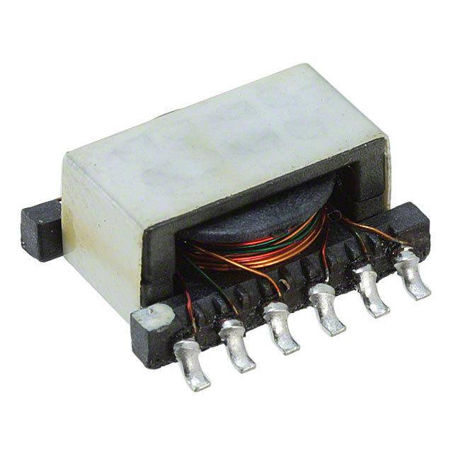
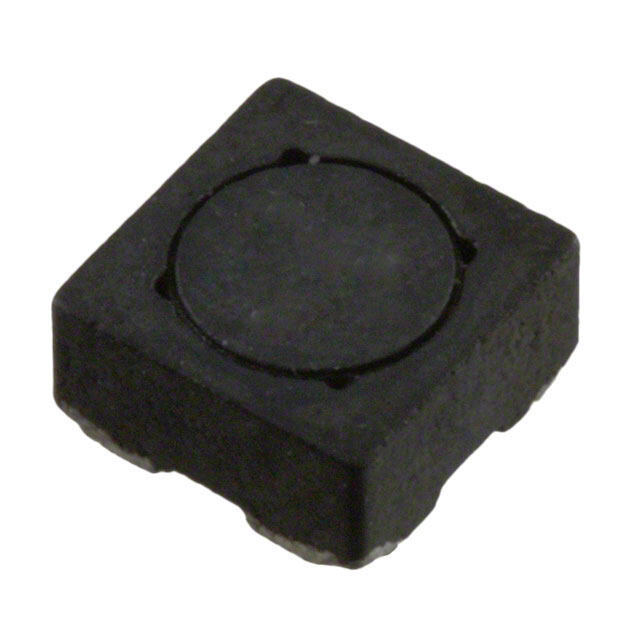
Eaton - Electronics Division的VPH1-0190-R是一款信号变压器,属于阵列式变压器类别。该型号主要用于电信、网络通信和工业控制系统等领域,适用于需要高效信号传输和电气隔离的应用场景。

VPH1-0190-R通常用于以太网接口、数据通信设备、交换机、路由器等网络设备中,支持高速信号传输,同时提供良好的电磁隔离,防止不同电路之间发生干扰或电压冲击,提升系统的稳定性和安全性。

该信号变压器还具备良好的共模抑制能力,有助于降低噪声干扰,保障数据传输的完整性。在工业自动化系统中,它可用于PLC(可编程逻辑控制器)与现场设备之间的信号隔离和传输,适应复杂电磁环境下的稳定运行。

此外,该器件符合RoHS环保标准,适合用于对环保要求较高的电子产品中。其阵列式设计有助于节省PCB空间,适用于高密度电路布局。

综上,VPH1-0190-R主要应用于通信设备、工业控制、网络基础设施等场景,具备信号隔离、噪声抑制和高效传输等功能,适合对性能和可靠性有较高要求的电子系统。
| 参数 | 数值 |
| 产品目录 | |
| DC电阻(DCR) | 344 毫欧最大 |
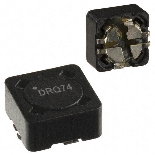
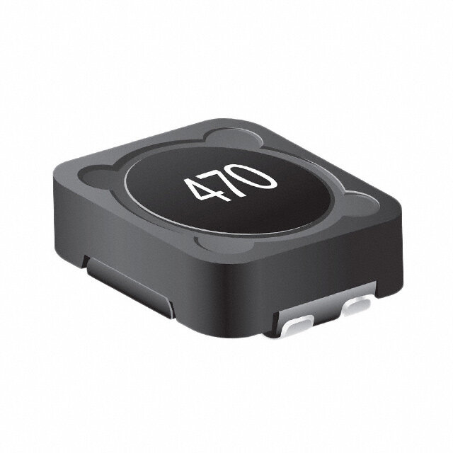
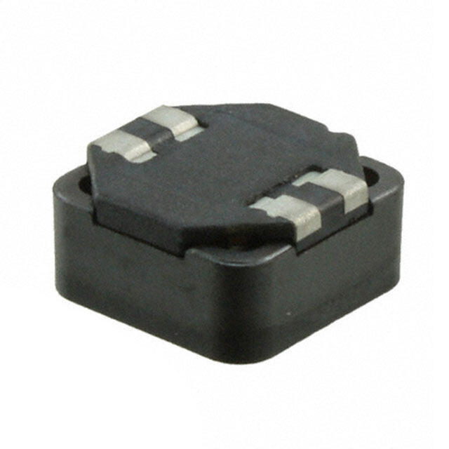
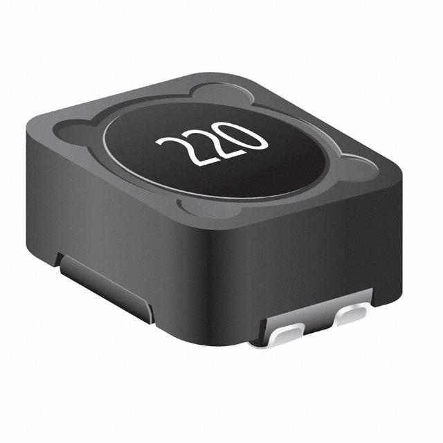
| 描述 | INDUCT ARRAY 6 COIL 27.4UH SMD固定电感器 27.4uH 0.29A 0.344ohms |
| 产品分类 | |
| 品牌 | Coiltronics / Eaton |
| 产品手册 | |
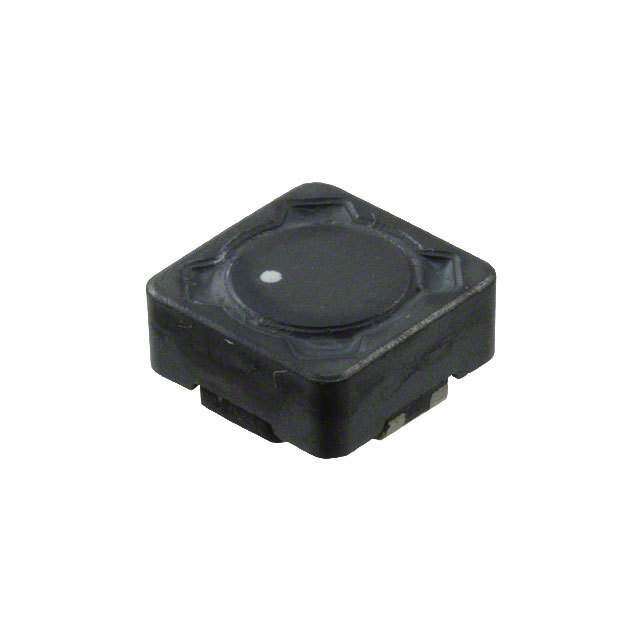
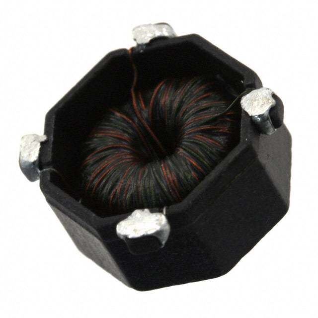
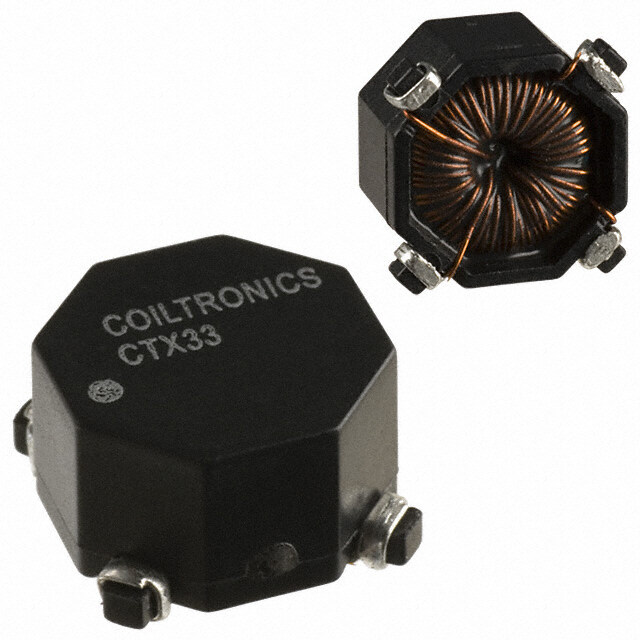
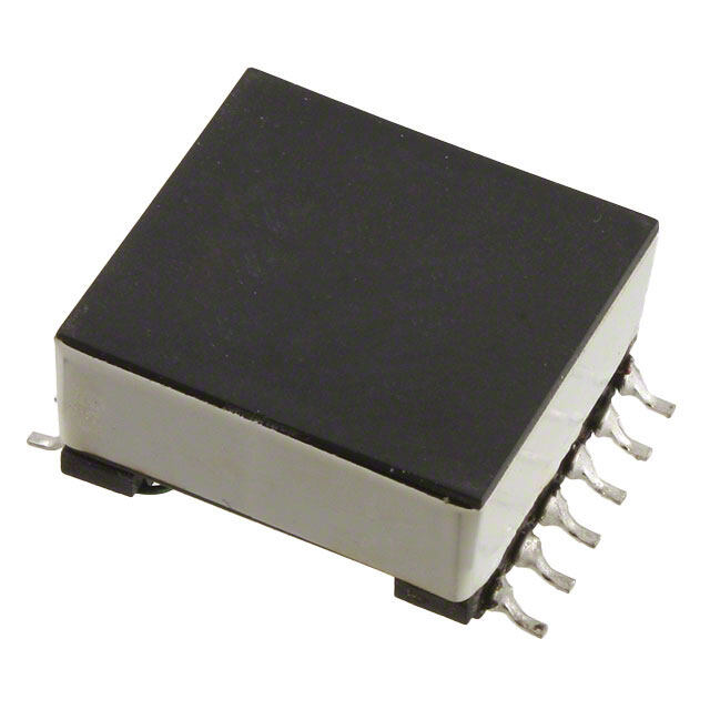
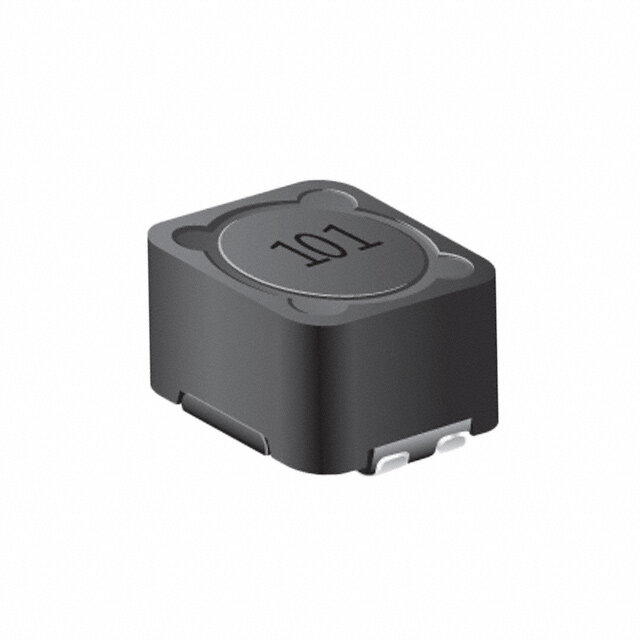
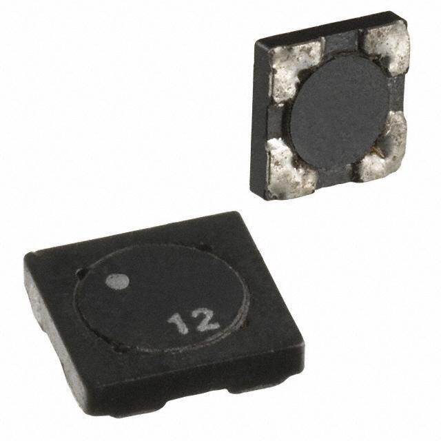
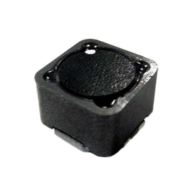
| 产品图片 |
|
| rohs | 符合RoHS无铅 / 符合限制有害物质指令(RoHS)规范要求 |
| 产品系列 | 固定电感器,Coiltronics / Eaton VPH1-0190-RVERSA-PAC® |
| 数据手册 | |
| 产品型号 | VPH1-0190-R |
| PCN组件/产地 | |
| 产品 | Inductors |
| 产品培训模块 | http://www.digikey.cn/PTM/IndividualPTM.page?site=cn&lang=zhs&ptm=25759 |
| 产品目录绘图 |
|
| 产品目录页面 | |
| 产品种类 | 固定电感器 |
| 其它名称 | 513-1194-6 |
| 包装 | Digi-Reel® |
| 单位重量 | 2.722 g |
| 商标 | Coiltronics / Eaton |
| 外壳宽度 | 9.2 mm |
| 外壳长度 | 12.9 mm |
| 外壳高度 | 6.2 mm |
| 大小/尺寸 | 0.508" 长 x 0.512" 宽(12.90mm x 13.00mm) |
| 安装类型 | 表面贴装 |
| 容差 | 20 % |
| 封装 | Reel |
| 封装/外壳 | 12-SMD |
| 屏蔽 | Unshielded |
| 工作温度范围 | - 40 C to + 85 C |
| 工厂包装数量 | 600 |
| 最大直流电流 | 290 mA |
| 最大直流电阻 | 344 mOhms |
| 标准包装 | 1 |
| 电感 | 27.4 uH |
| 电感-串联连接 | 986.4µH |
| 电感-并联连接 | 27.4µH |
| 电流 | 550mA |
| 端接类型 | SMD/SMT |
| 类型 | Inductors and Transformers |
| 系列 | VPH1 |
| 线圈数 | 6 |
| 芯体材料 | Ferrite |
| 高度 | 0.244"(6.20mm) |

1-Series.jpg)

1%20Series.jpg)


PDF Datasheet 数据手册内容提取
Effective August 2017 Technical Data 4301 Supersedes March 2007 VP VERSA-PAC® Inductors and Transformers (Surface Mount) Applications Inductors: buck, boost, coupled, choke, • filter, resonant, noise filtering, differential, forward, common mode Transformers: flyback, feed forward, push- • pull, multiple output, inverter, step-up, step- down, gate drive, base drive, wide band, pulse, control, impedance, isolation, bridging, ringer, converter, autoAutomotive electronics (under hood, interior/exterior) Telematics • Product features GPS • • Six winding, surface mount devices that • LED Lighting offer more than 500 usable inductor or LCD Display transformer configurations • • High power density and low profile • Portable media devices Low radiated noise and tightly coupled • windings Environmental data Power range from 1 Watt – 70 Watts • Storage temperature range (component): Frequency range to over 1 MHz • • -55 °C to +125 °C 500 Vac Isolation • Ferrite core material Operating temperature range: • • -40 °C to +125 °C (ambient plus self-temperature rise) Solder reflow temperature: • J-STD-020 (latest revision) compliant
Technical Data 4301 VP Effective August 2017 VERSA-PAC® Inductors and Transformers (Surface Mount) Product specifications Leakage Thermal Part (1) L(BASE) ISAT(BASE) IRMS(BASE) R(BASE) Volt-µSEC(BASE) EPEAK(BASE) Inductance Resistance Number µH (A) (A) Ohms µVs µJ (BASE)µH °C/Watt (NOM)(2) (TYP)(3)(4) (TYP)(3)(5) (MAX)(6) (MAX)(7) (TYP)(8) (TYP) (TYP)(9) VPH1-1400-R(10) 201.6 +/-30% 0.04 0.55 0.344 32.9 0.11 0.212 60.7 VP1-1400-R(10) 89.6 +/-30% 0.06 0.85 0.145 21.8 0.11 0.096 60.7 VPH1-0190-R 27.4 +/-20% 0.29 0.55 0.344 32.9 0.77 0.212 60.7 VP1-0190-R 12.2 +/-20% 0.43 0.85 0.145 21.8 0.77 0.096 60.7 VPH1-0102-R 14.7 +/-20% 0.53 0.55 0.344 32.9 1.45 0.212 60.7 VP1-0102-R 6.5 +/-20% 0.80 0.85 0.145 21.8 1.45 0.096 60.7 VPH1-0076-R 10.9 +/-20% 0.72 0.55 0.344 32.9 1.92 0.212 60.7 VP1-0076-R 4.9 +/-20% 1.06 0.85 0.145 21.8 1.92 0.096 60.7 VPH1-0059-R 8.5 +/-20% 0.92 0.55 0.344 32.9 2.48 0.212 60.7 VP1-0059-R 3.8 +/-20% 1.37 0.85 0.145 21.8 2.48 0.096 60.7 VPH2-1600-R(10) 160 +/-30% 0.07 0.95 0.159 48.3 0.29 0.165 44.0 VP2-1600-R(10) 78.4 +/-30% 0.10 1.26 0.090 33.7 0.29 0.083 44.0 VPH2-0216-R 21.6 +/-20% 0.53 0.95 0.159 48.3 2.11 0.165 44.0 VP2-0216-R 10.6 +/-20% 0.76 1.26 0.090 33.7 2.11 0.083 44.0 VPH2-0116-R 11.6 +/-20% 0.99 0.95 0.159 48.3 3.94 0.165 44.0 VP2-0116-R 5.7 +/-20% 1.41 1.26 0.090 33.7 3.94 0.083 44.0 VPH2-0083-R 8.3 +/-20% 1.39 0.95 0.159 48.3 5.47 0.165 44.0 VP2-0083-R 4.1 +/-20% 1.95 1.26 0.090 33.7 5.47 0.083 44.0 VPH2-0066-R 6.6 +/-20% 1.74 0.95 0.159 48.3 7.01 0.165 44.0 VP2-0066-R 3.2 +/-20% 2.50 1.26 0.090 33.7 7.01 0.083 44.0 VPH3-0780-R(10) 132 +/-30% 0.07 0.97 0.14 39.8 0.24 0.125 43.4 VP3-0780-R(10) 63.2 +/-30% 0.10 1.47 0.061 27.7 0.24 0.058 43.4 VPH3-0138-R 23.3 +/-20% 0.41 0.97 0.14 39.8 1.36 0.125 43.4 VP3-0138-R 11.2 +/-20% 0.59 1.47 0.061 27.7 1.36 0.058 43.4 VPH3-0084-R 14.2 +/-20% 0.67 0.97 0.14 39.8 2.23 0.125 43.4 VP3-0084-R 6.8 +/-20% 0.97 1.47 0.061 27.7 2.23 0.058 43.4 VPH3-0055-R 9.3 +/-20% 1.02 0.97 0.14 39.8 3.38 0.125 43.4 VP3-0055-R 4.5 +/-20% 1.46 1.47 0.061 27.7 3.38 0.058 43.4 VPH3-0047-R 7.94 +/-20% 1.19 0.97 0.14 39.8 4.00 0.125 43.4 VP3-0047-R 3.8 +/-20% 1.73 1.47 0.061 27.7 4.00 0.058 43.4 VPH4-0860-R(10) 159.65 +/-30% 0.11 1.41 0.0828 64.6 0.57 0.156 39.4 VP4-0860-R(10) 87.0 +/-30% 0.15 1.70 0.057 44.7 0.57 0.075 39.4 VPH4-0140-R 23.7 +/-20% 0.65 1.41 0.0828 64.6 3.54 0.156 39.4 VP4-0140-R 11.3 +/-20% 0.95 1.70 0.057 44.7 3.54 0.075 39.4 VPH4-0075-R 12.7 +/-20% 1.21 1.41 0.0828 64.6 6.55 0.156 39.4 VP4-0075-R 6.1 +/-20% 1.75 1.70 0.057 44.7 6.55 0.075 39.4 VPH4-0060-R 10.1 +/-20% 1.52 1.41 0.0828 64.6 8.16 0.156 39.4 VP4-0060-R 4.9 +/-20% 2.18 1.70 0.057 44.7 8.16 0.075 39.4 VPH4-0047-R 7.94 +/-20% 1.94 1.41 0.0828 64.6 10.52 0.156 39.4 VP4-0047-R 3.8 +/-20% 2.81 1.70 0.057 44.7 10.52 0.075 39.4 VPH5-1200-R(10) 173 +/-30% 0.14 1.70 0.0711 98.4 1.11 0.235 30.3 VP5-1200-R(10) 76.8 +/-30% 0.20 2.08 0.047 65.6 1.11 0.105 30.3 VPH5-0155-R 22.3 +/-20% 1.05 1.70 0.0711 98.4 8.83 0.235 30.3 VP5-0155-R 9.9 +/-20% 1.60 2.08 0.047 65.6 8.83 0.105 30.3 VPH5-0083-R 12 +/-20% 1.96 1.70 0.0711 98.4 16.07 0.235 30.3 VP5-0083-R 5.3 +/-20% 2.95 2.08 0.047 65.6 16.07 0.105 30.3 VPH5-0067-R 9.65 +/-20% 2.43 1.70 0.0711 98.4 19.83 0.235 30.3 VP5-0067-R 4.3 +/-20% 3.63 2.08 0.047 65.6 19.83 0.105 30.3 VPH5-0053-R 7.63 +/-20% 3.07 1.70 0.0711 98.4 25.10 0.235 30.3 VP5-0053-R 3.4 +/-20% 4.59 2.08 0.047 65.6 25.10 0.105 30.3 2 www.eaton.com/electronics
VP Technical Data 4301 VERSA-PAC® Inductors and Transformers (Surface Mount) Effective August 2017 Product specifications- notes (1) The first three or four digits in the part number signify the size of the (8) Maximum Energy capability of each winding.This is based on 30% package. The next four digits specify the AL, or nanoHenries per turn saturation of the core: squared. -R indicates RoHS compliant. (2) LBASE = Nominal Inductance of a single winding. EnergySERIES=S2x 21 x0.7LBASE xI2SAT(BASE) ((34)) IPBAeSEa iks cthuerr elensts tohra ot fw ISilAlT (BrAeSEs) ualnt din I R3MS0(BA%SE). saturation of the core. This EnergyPARALLEL=P2x 12 x0.7LBASE xI2SAT(BASE) current value assumes that equal current flows in all six windings. For applications in which all windings are not simultaneously driven For multiple windings, the energy capability varies as the square of (i.e. flyback, SEPIC, Cuk, etc.), the saturation current per winding the number of windings.For example, six windings (either parallel may be calculated as follows: or series) can store 36 times more energy than one winding. 6 x I ISAT = SAT(BASE) Number of Windings Driven (9) Thermal Resistance is the approximate surface temperature rise (5) RMS Current that results in a surface temperature of approximately per Watt of heat loss under still-air conditions.Heat loss is a 40 °C above ambient. The 40 °C rise occurs when the specified combination of core loss and wire loss.The number assumes the current flows through each of the six windings. underlying PCB copper area equals 150% of the component area. (6) Maximum DC Resistance of each winding. (7) For multiple windings in series, the volt-µsecondTOTAL (µVs) capability (10) These devices are designed for feed-forward applications, where varies as the number of windings in series (S): load current dominates magnitizing current. Volt-µsecTOTAL=SxVolt-µsec(BASE) VERSA-PAC temperature rise depends on total power losses and For multiple windings in parallel, the volt-µsecondTOTAL(µVs) capability size. Any other PCM configurations other than those suggested is as shown in the table above. could run hotter than acceptable. Certain topologies or applications must be analyzed for needed requirements and matched with the best VERSA-PAC size and configuration. Proper consideration must be used with all parameters, especially those associated with current rating, energy storage, or maximum volt-seconds. VERSA-PAC should not be used in off-line or safety related applications. The breakdown voltage from one winding to any other Dimensions- mm winding is 500 VAC maximum. VP1 and VPH1 TOP VIEW RECOMMENDED PCB LAYOUT WHITE DOT PIN #1 LOGO (OPTIONAL) N 1 12 M P D 1 12 (10PLCS) (12 PLCS) V PH A K _-_ J (12PLCS) COMPONENT 0 NOTES: ___ SIDE (10PLCS) 6 7 1)Tolerances A - I are ± 0.25 mm unless specified 6 7 otherwise. B L 2)Tolerances J - P are +/- 0.1 mm unless specified (12PLCS) C otherwise. 4 10 3)Marking: a)Dot for pin #1 identification FRONT VIEW b) VP(H)x-xxx (product code, size, 4 digit part number per family table.) 1 7 E 5 11 c) Versa Pac Logo (optional) d) wwllyy = (date code) R = (revision level) 4)All soldering surfaces must be coplanar within 0.102 mm. F 26 182 5)Packaged in tape and reel 600 parts per reel I G H (12 PLCS) (2 PLCS) 3 9 WWLLYY R 1:1:1:1:1:1 AAA B E F G H I J K L M N O P mm mm mm mm mm mm mm mm mm mm mm mm mm mm mm mm max ref max ref ref max ref ref ref ref ref max VP1 and VPH1 12.9 9.2 13.0 0.7 5.9 6.2 1.5 0.1 0.25 11.5 1.5 2.25 9.7 14.2 2.0 0.5 www.eaton.com/electronics 3
VP Technical Data 4301 VERSA-PAC® Inductors and Transformers (Surface Mount) Effective August 2017 Dimensions- mm VP2 and VPH2 TOP VIEW RECOMMENDED PCB LAYOUT WHITE DOT PIN #1 LOGO (OPTIONAL) N 1 12 M P D 1 12 (10PLCS) (12 PLCS) V PH A K _-_ J (12PLCS) COMPONENT 0 NOTES: ___ SIDE (10PLCS) 6 7 1)Tolerances A - I are ± 0.25 mm unless specified 6 7 otherwise. B L 2)Tolerances J - P are +/- 0.1 mm unless specified (12PLCS) otherwise. C 4 10 3)Marking: a)Dot for pin #1 identification FRONT VIEW b) VP(H)x-xxx (product code, size, 4 digit part number per family table.) 1 7 c) Versa Pac Logo (optional) E 5 11 d) wwllyy = (date code) R = (revision level) 4)All soldering surfaces must be coplanar within 0.102 mm. 2 8 5)Packaged in tape and reel 300 parts per reel F 6 12 I G H (12 PLCS) (2 PLCS) 3 9 WWLLYY R 1:1:1:1:1:1 A B C D E F G H I J K L M N O P mm mm mm mm mm mm mm mm mm mm mm mm mm mm mm mm max ref max ref ref max ref ref ref ref ref max VP2 and VPH2 16.3 12.0 16.8 0.7 6.7 7.8 2.0 0.1 0.30 14.25 1.75 2.5 13.0 18.0 2.5 0.75 VP3 and VPH3 M WHITE DOT TOP VIEW L O PIN #1 1 12 (10PLCS) J 1 12 I (12PLCS) COMPONENT N D SIDE VPH_-____ (10PLCS) (12 PLCS) LOGO A 6 7 (OPTIONAL) K(12PLCS) NOTES: 6 7 1 4 1)Tolerances A - I are ± 0.25 mm unless specified B otherwise. 2)Tolerances J - P are +/- 0.1 mm unless specified C otherwise. 12 9 3)Marking: 2 5 a)Dot for pin #1 identification FRONT VIEW b) VP(H)x-xxx (product code, size, 4 digit part number per family table.) c) Versa Pac Logo (optional) 11 8 d) wwllyy = (date code) R = (revision level) E 3 6 4)All soldering surfaces must be coplanar within 0.102 mm. 5)Packaged in tape and reel 200 parts per reel H G (12 PLCS) (12 PLCS) F(2 PLCS) 10 7 1:1:1:1:1:1 A B C D E F G H I J K L M N O mm mm mm mm mm mm mm mm mm mm mm mm mm mm mm max ref max ref max ref ref ref ref ref max VP3 and VPH3 17.1 16.0 22.3 0.7 8.4 3.0 0.1 0.4 14.49 1.79 3.43 16.88 23.74 2.54 0.75 4 www.eaton.com/electronics
VP Technical Data 4301 VERSA-PAC® Inductors and Transformers (Surface Mount) Effective August 2017 Dimensions- mm VP4 and VPH4 M WHITE DOT TOP VIEW L O PIN #1 1 12 (10PLCS) J 1 12 I (12PLCS) COMPONENT N D SIDE VPH_-____ (10PLCS) (12 PLCS) LOGO A 6 7 (OPTIONAL) NOTES: K(12PLCS) 6 7 1)Tolerances A - I are ± 0.25 mm unless specified 1 4 otherwise. B 2)Tolerances J - P are +/- 0.1 mm unless specified otherwise. C 3)Marking: 12 9 a)Dot for pin #1 identification 2 5 b) VP(H)x-xxx (product code, size, 4 digit part FRONT VIEW number per family table.) c) Versa Pac Logo (optional) d) wwllyy = (date code) R = (revision level) 11 8 4)All soldering surfaces must be coplanar within E 3 6 0.102 mm. 5) Bulk packaged H G For tape and reel add TR to part number: (i.e. (12 PLCS) F(2 PLCS) (12 PLCS) 10 7 VP4-0140TR-R) 140 parts per reel 1:1:1:1:1:1 A B C D E F G H I J K L M N O mm mm mm mm mm mm mm mm mm mm mm mm mm mm mm max ref max ref max ref ref ref ref ref max VP4 and VPH4 18.0 18.0 24.6 0.7 10.0 3.3 0.1 0.4 14.25 1.75 3.43 19.14 26.0 2.5 0.75 VP5 and VPH5 M WHITE DOT TOP VIEW L O PIN #1 1 12 (10PLCS) J 1 12 I (12PLCS) COMPONENT N D SIDE VPH_-____ (10PLCS) (12 PLCS) LOGO A 6 7 (OPTIONAL) K(12PLCS) NOTES: 6 7 1 4 1)Tolerances A - I are ± 0.25 mm unless specified B otherwise. 2)Tolerances J - P are +/- 0.1 mm unless specified C otherwise. 12 9 3)Marking: 2 5 a)Dot for pin #1 identification FRONT VIEW b) VP(H)x-xxx (product code, size, 4 digit part number per family table.) c) Versa Pac Logo (optional) 11 8 d) wwllyy = (date code) R = (revision level) E 3 6 4)All soldering surfaces must be coplanar within 0.102 mm. H 5) Bulk packaged G (12 PLCS) (12 PLCS) F(2 PLCS) 10 7 For tape and reel add TR to part number: (i.e. VP5-0155TR-R) 115 parts per reel 1:1:1:1:1:1 A B C D E F G H I J K L M N O mm mm mm mm mm mm mm mm mm mm mm mm mm mm mm max ref max ref max ref ref ref ref ref max VP5 and VPH5 21.0 21.0 28.5 0.7 10.8 2.95 0.1 0.4 17.25 2.25 3.15 22.7 29.0 3.0 0.75 www.eaton.com/electronics 5
VP Technical Data 4301 Effective August 2017 VERSA-PAC® Inductors and Transformers (Surface Mount) How to use multiple windings Discrete inductors combine like resistors, when connected in series or parallel. For example, inductors in series add and inductors in parallel reduce in a way similar to Ohm’s Law. L = L1 + L2 + L3...Ln Series L = 1/[1/L1 + 1/L2 + 1/L3....1/Ln] Parallel Windings on the same magnetic core behave differently.Two windings in series result in four times the inductance of a single winding. This is because the inductance varies proportionately to the square of the turns. Paralleled VERSA-PAC windings result in no change to the net inductance because the total number of turns remains unchanged;only the effective wire size becomes larger. Two parallel windings result in approximately twice the current carrying capability of a single winding.The net inductance of a given PCM configuration is based on the number of windings in series squared multiplied by the inductance of a single winding (L ).The current rating of a PCMconfiguration BASE is derived by multiplying the maximum current rating of one winding (I )by the number of windings in parallel. Examples BASE ofsimple two-winding devices are shown below: Series Connected (2 Windings) Parallel Connected (2Windings) 10µH 1Amp 10µH 10µH 1Amp 1Amp 10µH 1Amp L = L x S2 I = I x P L = L x S2 I = I x P TOTAL BASE MAX BASE TOTAL BASE MAX BASE = 10 µH x 22 = 1 Amp x 1 = 10 µH x 12 = 1 Amp x 2 = 40 µH = 1 Amp = 10 µH = 2 Amps Where: L = Inductance of a single winding BASE P = Number of windings in parallel (use 1 with all windings in series) S = Number of windings in series I = Maximum current rating of one winding BASE 6 www.eaton.com/electronics
VP Technical Data 4301 VERSA-PAC® Inductors and Transformers (Surface Mount) Effective August 2017 How to pin-configure VERSA-PAC® Each VERSA-PAC can be configured in a variety of ways by simply connecting pins together on the Printed Circuit Board (PCB). As shown below, the connections on the PCB are equal to the pin configuration statement shown at the bottom of the schematic symbol. Connecting a number of windings in parallel will increase the current carrying capability, while connecting in series will multiply the inductance. Each VERSA-PAC part can be configured in at least 6 combinations for inductor use or configured in at least 15 turns ratios for transformer applications. The VERSA-PAC allows for at least 500 magnetic configurations. The PCM configurations can either be created by the designer or simply chosen from the existign PCM diagrams. The following inductor example shows 6 windings in series, which result in an inductance of 36 times the base inductance and 1 times the base current. INDUCTOR EXAMPLE FOR SIZES VP3, VP4 AND VP5 L =36 x L TOTAL BASE Component View =36 times the base(cid:13) 1 4 Inductance from Data Table. 1 12 1 12 9 2 5 11 8 3 6 7 10 7 6 7 PIN CONFIGURATIONS(cid:13) (2,12)(3,11)(4,10)(5,9)(6,8) Each VERSA-PAC may be used in at least 15 transformer applications. More than 375 transformer combinations may be achieved using the available VERSA-PAC parts. TRANSFORMER EXAMPLE FOR SIZES VP3, VP4 AND VP5 1:5 1 4 1 12 L =1xL PRIMARY BASE 12 9 1 2 2 5 I =1xI I =1xI 11 8 PRI BASE SEC BASE 3 6 12 7 10 7 6 7 PIN CONFIGURATIONS(cid:13) (3,11)(4,10)(5,9)(6,8) The PCM configurations may be selected from the examples above or created by the designer. The printed circuit board layout in each example illustrates the connections to obtain the desired inductance or turns ratio. The examples may be used by the PCB designer to configure VERSA-PAC as desired. To assist the designer, VERSA-PAC phasing, coupling and thermal issues have been considered in each of the PCM configurations illustrated. Additionally, the inductance and current ratings, as a function of the respective base values are shown in each PCM example. It is important to carefully select the proper VERSA-PAC part in order to minimize the component size without exceeding the RMS current capability or saturating the core. The Product specification table indicates maximum ratings. www.eaton.com/electronics 7
Technical Data 4301 VP Effective August 2017 VERSA-PAC® Inductors and Transformers (Surface Mount) ® VERSA-PAC Performance characteristics Bipolar (Push-Pull) Power vs Frequency Inductance characteristics 70.0 60.0 OCL vs.Isat 100.0% 50.0 90.0% VP 5 40.0 atts 80.0% W 30.0 VP 4 70.0% 20.0 CL 60.0% VP 3 O 10.0 of 50.0% VP 2 % 0.0 VP 1 40.0% 100 200 300 400 500 Frequency, kHz 30.0% Unipolar (Flyback) Power vs Frequency 20.0% 40.0 10.0% 35.0 0.0% 0.0% 20.0% 40.0% 60.0% 80.0% 100.0% 120.0% 140.0% 160.0% 180.0% 200.0% 30.0 %of Isat VP5 25.0 atts 20.0 W VP 4 15.0 VP 3 10.0 VP 2 5.0 These curves represent typical power handling capability. VP 1 0.0 100 200 300 400 500 Indicated power levels may not be achievable with all configurations. Frequency, kHz 3.3V Buck Converter 5V to 3.3V Buck Converter With 5V Output This circuit utilizes the gap of the VP5-0083 to handle the 12.5 This circuit minimizes both board space and cost by eliminating a Amp output current without saturating. In each of the fiveVERSA- second regulator. VERSA-PAC’sgap serves to prevent core PACsizes, the gap is varied to achieve a selection of specific saturation during the switch on-time and also stores energy for the inductance and current values (see VERSA-PACData Table). +5V load which is delivered during the flybackinterval. The +3.3V buck winding is configured by placing two windings in series while All six windings are connected in parallel to minimizeAC/DC the +5V is generated by an additional flyback winding stacked on copper losses and to maximize heat dissipation.With VERSA- the 3.3V output.Extra windings are paralleled with primary PAC,this circuit works well at or above 300 KHz.Also, the closed windings to handle more current.The turns ratio of 2:1 adds 1.67V flux-path EFD geometryenables much lower radiation to the +3.3V during the flyback interval to achieve +5V. characteristics than open-path bobbin core style components. +V +V VERSA-PAC(cid:13) VP5-0083 Synchronous(cid:13) 1234 1119210 VVEPR5S-A0-0P8A3C(cid:13) RTN SyCnocnhItCrroonlleoru(cid:13)s(cid:13) 1,2 7 +51VA@(cid:13) ConItCroller(cid:13) 56 87 +132.3.5VA@ (cid:13) 132,4,1,51 6 + + LEVEL SHIFT 10,9,8 RTN + +34..32VA@ (cid:13) LITHIUM-ION BATTERY TO 3.3V SEPIC CONVERTER (cid:13) VERSA-PAC(cid:13) VP5-0083 The voltage of a Lithium-Ion Battery varies above and below 121110 456 +3.3V depending on the degree of charge. The SEPIC + +3.3V@ (cid:13) configuration takes advantage of VERSA-PAC’s multiple tightly 6A coupled windings. This results in lower ripple current which lowers + ConItCro(cid:13)ller(cid:13) W/Integral(cid:13) 123 987 noise and core losses substantially. The circuit does not require a Switch + snubber to control the voltage “spike”associated with switch turn- off,and is quite efficient due to lower RMS current in the windings. 8 www.eaton.com/electronics
VP Technical Data 4301 VERSA-PAC® Inductors and Transformers (Surface Mount) Effective August 2017 Solder Reflow Profile TP T -5°C TTaabbllee 11 -- SSttaannddaarrdd SSnnPPbb SSoollddeerr ((TTcc)) C Max. Ramp Up Rate = 3°C/s tP Volume Volume Max. Ramp Down Rate = 6°C/s Package mm3 mm3 T Thickness <350 >_350 L Preheat t <2.5mm 235°C 220°C A >_2.5mm 220°C 220°C T e smax atur TTaabbllee 22 -- LLeeaadd ((PPbb)) FFrreeee SSoollddeerr ((TTcc)) mper Tsmin Volume Volume Volume e t Package mm3 mm3 mm3 T s Thickness <350 33355500 - >2000 <1.6mm 260°C 260°C 260°C 1.6 – 2.5mm 260°C 250°C 245°C >2.5mm 250°C 245°C 245°C 25°C Time 25°C to Peak Time Reference JDEC J-STD-020 Profile Feature Standard SnPb Solder Lead (Pb) Free Solder Preheat and Soak (cid:129)Temperature min.(Tsmin) 100°C 150°C (cid:129)Temperature max.(Tsmax) 150°C 200°C (cid:129)Time (Tsminto Tsmax) (ts) 60-120 Seconds 60-120 Seconds Average ramp up rate Tsmaxto Tp 3°C/ Second Max. 3°C/ Second Max. Liquidous temperature (TL) 183°C 217°C Time at liquidous (tL) 60-150 Seconds 60-150 Seconds Peak package body temperature (TP)* Table 1 Table 2 Time (tp)** within 5 °C of the specified classification temperature (Tc) 20 Seconds** 30 Seconds** Average ramp-down rate (Tpto Tsmax) 6°C/ Second Max. 6°C/ Second Max. Time 25°C to Peak Temperature 6 Minutes Max. 8 Minutes Max. *Tolerance for peak profile temperature (Tp) is defined as a supplier minimum and a user maximum. ** Tolerance for time at peak profile temperature (tp) is defined as a supplier minimum and a user maximum. Life Support Policy: Eaton does not authorize the use of any of its products for use in life support devices or systems without the express written approval of an officer of the Company. Life support systems are devices which support or sustain life, and whose failure to perform, when properly used in accordance with instructions for use provided in the labeling, can be reasonably expected to result in significant injury to the user. Eaton reserves the right, without notice, to change design or construction of any products and to discontinue or limit distribution of any products. Eaton also reserves the right to change or update, without notice, any technical information contained in this bulletin. Eaton Electronics Division 1000 Eaton Boulevard Cleveland, OH 44122 United States www.eaton.com/electronics © 2017 Eaton All Rights Reserved Eaton is a registered trademark. Printed in USA Publication No. 4301 All other trademarks are property August 2017 of their respective owners.