ICGOO在线商城 > 电感器,线圈,扼流圈 > 阵列,信号变压器 > IHCL4040DZER2R2M5A
 Datasheet下载
- 型号: IHCL4040DZER2R2M5A
- 制造商: Vishay
- 库位|库存: xxxx|xxxx
- 要求:
| 数量阶梯 | 香港交货 | 国内含税 |
| +xxxx | $xxxx | ¥xxxx |
查看当月历史价格
查看今年历史价格
IHCL4040DZER2R2M5A产品简介:
ICGOO电子元器件商城为您提供IHCL4040DZER2R2M5A由Vishay设计生产,在icgoo商城现货销售,并且可以通过原厂、代理商等渠道进行代购。 IHCL4040DZER2R2M5A价格参考。VishayIHCL4040DZER2R2M5A封装/规格:阵列,信号变压器, Shielded 2 Coil Inductor Array Nonstandard。您可以下载IHCL4040DZER2R2M5A参考资料、Datasheet数据手册功能说明书,资料中有IHCL4040DZER2R2M5A 详细功能的应用电路图电压和使用方法及教程。
Vishay Dale的IHCL4040DZER2R2M5A是一款磁性阵列信号变压器,常用于需要信号隔离和电压变换的电子电路中。该型号的具体应用场景包括:

1. 工业控制系统:用于PLC、工业计算机及自动化设备中,实现信号隔离,提高系统抗干扰能力与安全性。
2. 通信设备:适用于以太网、CAN总线、RS-485等通信接口中,实现差分信号传输与电气隔离,保障设备与数据传输的稳定性。
3. 电源管理模块:在DC-DC转换器或隔离型电源中作为信号传输组件,实现控制信号的隔离与传递。
4. 测试与测量仪器:用于示波器、信号发生器等精密仪器中,确保测量信号的隔离与完整性,防止地环路干扰。
5. 汽车电子系统:如车载通信模块、传感器接口等,满足汽车环境对可靠性和抗干扰能力的高要求。

该器件具有良好的隔离性能、高频响应和紧凑设计,适合高密度PCB布局,广泛应用于需要信号完整性与电气隔离的各类高性能电子系统中。
| 参数 | 数值 |
| 产品目录 | |
| DC电阻(DCR) | 7.5 毫欧最大 |
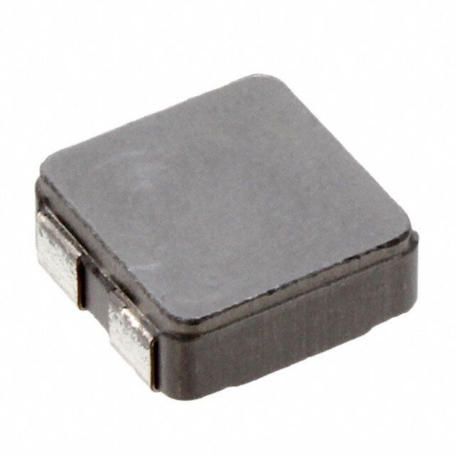
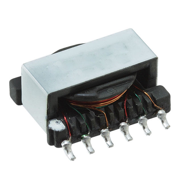
| 描述 | INDUCT ARRAY 2 COIL 2.2UH SMD耦合电感 2.2uH 20% |
| 产品分类 | |
| 品牌 | Vishay / DaleVishay Dale |
| 产品手册 | |
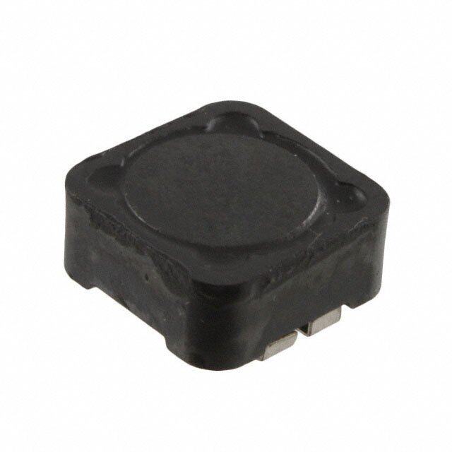
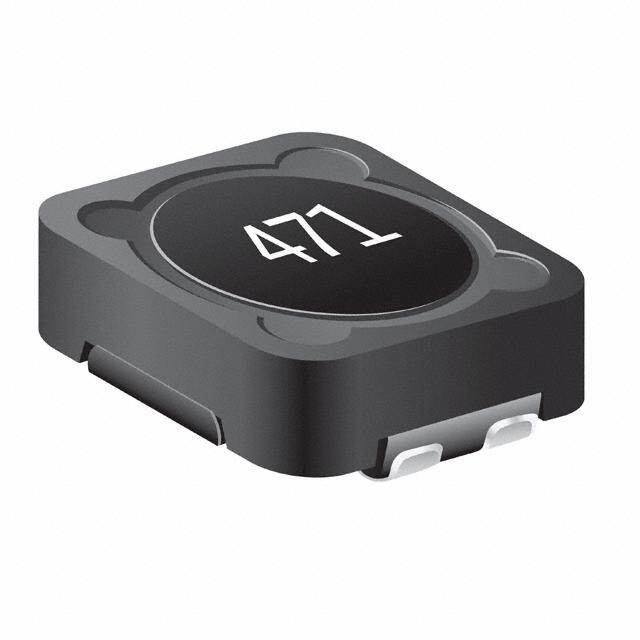
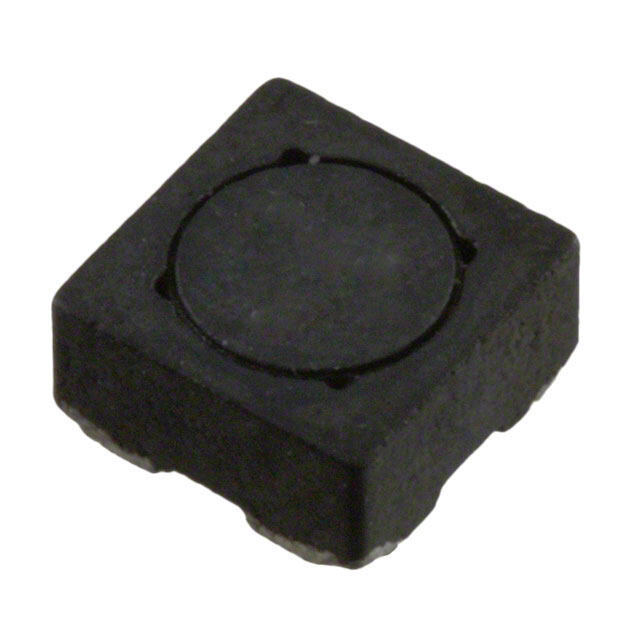
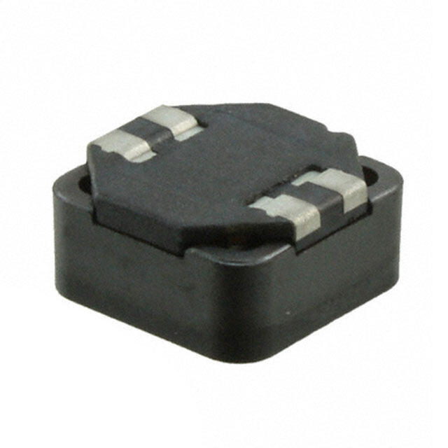
| 产品图片 |
|
| rohs | 符合RoHS无铅 / 符合限制有害物质指令(RoHS)规范要求 |
| 产品系列 | 耦合电感,Vishay / Dale IHCL4040DZER2R2M5AIHLP |
| mouser_ship_limit | 该产品可能需要其他文件才能进口到中国。 |
| 数据手册 | |
| 产品型号 | IHCL4040DZER2R2M5AIHCL4040DZER2R2M5A |
| 产品 | Coupled Inductors |
| 产品种类 | 耦合电感 |
| 其它名称 | 541-1907-6 |
| 包装 | Digi-Reel® |
| 商标 | Vishay / Dale |
| 外壳宽度 | 10.16 mm |
| 外壳长度 | 10.67 mm |
| 外壳高度 | 4 mm |
| 大小/尺寸 | 0.420" 长 x 0.400" 宽 (10.67mm x 10.16mm) |
| 安装类型 | 表面贴装 |
| 安装风格 | SMD/SMT |
| 容差 | 20 %±20% |
| 封装 | Reel |
| 封装/外壳 | 4-SMD,无引线(DFN,LCC) |
| 尺寸 | 10.16 mm W x 10.67 mm L x 4 mm H |
| 屏蔽 | 无屏蔽 |
| 工作温度范围 | - 55 C to + 155 C |
| 引线间隔 | 1.778 mm |
| 最大直流电流 | 9.5 A |
| 最大直流电阻 | 15 mOhms |
| 标准包装 | 1 |
| 电感-串联 | 2.2 uH |
| 电感-串联连接 | 8.8µH |
| 电感-并联连接 | 2.2µH |
| 电流 | 9.5A |
| 端接类型 | SMD/SMT |
| 系列 | IHCL-4040DZ-5A |
| 线圈数 | 2 |
| 高度 | 0.158"(4.01mm) |


PDF Datasheet 数据手册内容提取
IHCL-4040DZ-5A 2.2 μH www.vishay.com Vishay Dale Low-Profile, High-Current Coupled Inductor FEATURES • High temperature, up to 155 °C • Shielded construction • Frequency range up to 5.0 MHz • Lowest DCR/μH in this package size • Handles high transient current spikes without saturation • Ultra low buzz noise, due to composite DESIGN SUPPORT TOOLS click logo to get started construction • Coupling is > 90 % - optimized for SEPIC converters Models Design Tools • AEC-Q200 qualified Available Available • Patent pending STANDARD ELECTRICAL SPECIFICATIONS • Material categorization: for definitions of compliance L 0 please see www.vishay.com/doc?99912 INDUCTANCE HEAT ± 20 % AT DCR DCR RATING SATURATION APPLICATIONS 100 kHz, NOM. MAX. CURRENT CURRENT 0.25 V, 0 A 25 °C 25 °C DC TYP. DC TYP. • SEPIC converters (μH) (m) (m) (A) (1) (A) (2) L 2.2 16.3 17.5 8.4 11.0 • DC/DC converters 1-2 L3-4 2.2 16.3 17.5 8.0 15.0 • Common mode applications L 1-4 9.0 32.6 35.0 5.4 5.5 • LED lighting (L shorted) 2-3 L 1-3 0.1 32.6 35.0 5.4 See note (3) (L2-4 shorted) DIMENSIONS in inches [millimeters] L Common Mode Side View Top View Side View (1-3 and 2.2 8.2 8.7 13.3 12.5 2-4 shorted) 4 3 0.110 ± 0.005 LDifferential Mode 4 0.400 ± 0.005 [2.79 ± 0.127] 3 (1-4 and 0.1 8.2 8.7 13.3 See note (3) [10.16 ± 0.127] 1 2 2-3 shorted) 1 2 Notes 0.080 ± 0.005 • All test data is referenced to 25 °C ambient [2.03 ± 0.127] 0.158 0.420 ± 0.010 [4.0] • Operating temperature range -55 °C to +155 °C [10.67 ± 0.254] Max. • The part temperature (ambient + temp. rise) should not exceed 155 °C under worst case operating conditions. Circuit design, Typical Pad Layout Bottom View Schematic component placement, PWB trace size and thickness, airflow 0.220 [5.588] 0.084 ± 0.015 and other cooling provisions all affect the part temperature. Part [2.13 ± 0.381] 2 3 temperature should be verified in the end application 4 3 1 2 • Rated operating voltage (across inductor) = 50 V 0.070 • SEPIC operation can generate up to 2x the input or output [1.778] 1 2 4 3 voltage across the inductor. Please limit VIN and VOUT to 25 V 1 4 max. for SEPIC operation 0.120 0.125 (1) DC current (A) that will cause an approximate T of 40 °C [3.048] [3.175] 0.232 ± 0.030 (2) DC current (A) that will cause L to drop approximately 20 % [5.89 ± 0.762] 0 (3) In this configuration, current flowing opposite directions through coils cancels and the 0.1 μH inductance is very stable with varying current. Observe the heat rating current to avoid excessive temperature rise in this configuration DESCRIPTION IHCL-4040DZ-5A 2.2 μH ± 20 % ER e3 MODEL INDUCTANCE VALUE INDUCTANCE TOLERANCE PACKAGE CODE JEDEC® LEAD (Pb)-FREE STANDARD GLOBAL PART NUMBER I H C L 4 0 4 0 D Z E R 2 R 2 M 5 A PRODUCT FAMILY SIZE PACKAGE INDUCTANCE TOL. SERIES CODE VALUE Revision: 09-Feb-18 1 Document Number: 34355 For technical questions, contact: magnetics@vishay.com THIS DOCUMENT IS SUBJECT TO CHANGE WITHOUT NOTICE. THE PRODUCTS DESCRIBED HEREIN AND THIS DOCUMENT ARE SUBJECT TO SPECIFIC DISCLAIMERS, SET FORTH AT www.vishay.com/doc?91000
IHCL-4040DZ-5A 2.2 μH www.vishay.com Vishay Dale PERFORMANCE GRAPHS 2.2 µH 4 H) μ 3 E ( L1-2 C N A 2 L3-4 T C U D 1 N I 0 0 5 10 15 20 DC CURRENT (A) 2.2 µH 15 100 H) 12 L1-2Q 80 μ E ( C 9 60 N A Q CT 6 40 U L3-4Q D IN 3 L1-2 20 L3-4 0 0 0.1 1 10 100 FREQUENCY (MHz) 2.2 µH 100 C) 80 °E ( SERIES L1-2 L3-4 Parallel R 60 U T A R 40 E P M E 20 T 0 0 5 10 15 20 25 DC CURRENT (A) Revision: 09-Feb-18 2 Document Number: 34355 For technical questions, contact: magnetics@vishay.com THIS DOCUMENT IS SUBJECT TO CHANGE WITHOUT NOTICE. THE PRODUCTS DESCRIBED HEREIN AND THIS DOCUMENT ARE SUBJECT TO SPECIFIC DISCLAIMERS, SET FORTH AT www.vishay.com/doc?91000
Legal Disclaimer Notice www.vishay.com Vishay Disclaimer ALL PRODUCT, PRODUCT SPECIFICATIONS AND DATA ARE SUBJECT TO CHANGE WITHOUT NOTICE TO IMPROVE RELIABILITY, FUNCTION OR DESIGN OR OTHERWISE. Vishay Intertechnology, Inc., its affiliates, agents, and employees, and all persons acting on its or their behalf (collectively, “Vishay”), disclaim any and all liability for any errors, inaccuracies or incompleteness contained in any datasheet or in any other disclosure relating to any product. Vishay makes no warranty, representation or guarantee regarding the suitability of the products for any particular purpose or the continuing production of any product. To the maximum extent permitted by applicable law, Vishay disclaims (i) any and all liability arising out of the application or use of any product, (ii) any and all liability, including without limitation special, consequential or incidental damages, and (iii) any and all implied warranties, including warranties of fitness for particular purpose, non-infringement and merchantability. Statements regarding the suitability of products for certain types of applications are based on Vishay’s knowledge of typical requirements that are often placed on Vishay products in generic applications. Such statements are not binding statements about the suitability of products for a particular application. It is the customer’s responsibility to validate that a particular product with the properties described in the product specification is suitable for use in a particular application. Parameters provided in datasheets and / or specifications may vary in different applications and performance may vary over time. All operating parameters, including typical parameters, must be validated for each customer application by the customer’s technical experts. Product specifications do not expand or otherwise modify Vishay’s terms and conditions of purchase, including but not limited to the warranty expressed therein. Except as expressly indicated in writing, Vishay products are not designed for use in medical, life-saving, or life-sustaining applications or for any other application in which the failure of the Vishay product could result in personal injury or death. Customers using or selling Vishay products not expressly indicated for use in such applications do so at their own risk. Please contact authorized Vishay personnel to obtain written terms and conditions regarding products designed for such applications. No license, express or implied, by estoppel or otherwise, to any intellectual property rights is granted by this document or by any conduct of Vishay. Product names and markings noted herein may be trademarks of their respective owners. © 2017 VISHAY INTERTECHNOLOGY, INC. ALL RIGHTS RESERVED Revision: 08-Feb-17 1 Document Number: 91000