ICGOO在线商城 > VJ2225Y474KBBAT4X

 Datasheet下载
- 型号: VJ2225Y474KBBAT4X
- 制造商: Vishay
- 库位|库存: xxxx|xxxx
- 要求:
| 数量阶梯 | 香港交货 | 国内含税 |
| +xxxx | $xxxx | ¥xxxx |
查看当月历史价格
查看今年历史价格
VJ2225Y474KBBAT4X产品简介:
ICGOO电子元器件商城为您提供VJ2225Y474KBBAT4X由Vishay设计生产,在icgoo商城现货销售,并且可以通过原厂、代理商等渠道进行代购。 提供VJ2225Y474KBBAT4X价格参考以及VishayVJ2225Y474KBBAT4X封装/规格参数等产品信息。 你可以下载VJ2225Y474KBBAT4X参考资料、Datasheet数据手册功能说明书, 资料中有VJ2225Y474KBBAT4X详细功能的应用电路图电压和使用方法及教程。
| 参数 | 数值 |
| 产品目录 | |
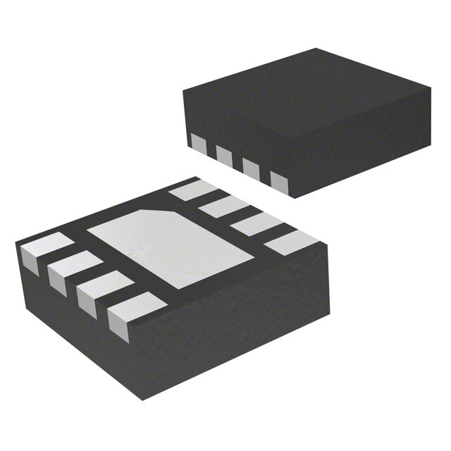
| 描述 | CAP CER 0.47UF 100V 10% X7R 2225 |
| 产品分类 | |
| 品牌 | Vishay Vitramon |
| 数据手册 | |
| 产品图片 |
|
| 产品型号 | VJ2225Y474KBBAT4X |
| rohs | 无铅 / 符合限制有害物质指令(RoHS)规范要求 |
| 产品系列 | VJ |
| 产品培训模块 | http://www.digikey.cn/PTM/IndividualPTM.page?site=cn&lang=zhs&ptm=23689 |
| 产品目录绘图 |
|
| 产品目录页面 | |
| 其它名称 | 720-1088-2 |
| 包装 | 带卷 (TR) |
| 厚度(最大值) | 0.086"(2.18mm) |
| 大小/尺寸 | 0.226" 长 x 0.250" 宽(5.74mm x 6.35mm) |
| 安装类型 | 表面贴装,MLCC |
| 容差 | ±10% |
| 封装/外壳 | 2225(5763 公制) |
| 工作温度 | -55°C ~ 125°C |
| 应用 | Boardflex 敏感 |
| 引线形式 | - |
| 引线间距 | - |
| 标准包装 | 1,000 |
| 温度系数 | X7R |
| 特性 | 软端子,高电压 |
| 特色产品 | http://www.digikey.com/cn/zh/ph/Vishay/VJSeries.html |
| 电压-额定 | 100V |
| 电容 | 0.47µF |
| 等级 | - |
| 高度-安装(最大值) | - |


- 商务部:美国ITC正式对集成电路等产品启动337调查
- 曝三星4nm工艺存在良率问题 高通将骁龙8 Gen1或转产台积电
- 太阳诱电将投资9.5亿元在常州建新厂生产MLCC 预计2023年完工
- 英特尔发布欧洲新工厂建设计划 深化IDM 2.0 战略
- 台积电先进制程称霸业界 有大客户加持明年业绩稳了
- 达到5530亿美元!SIA预计今年全球半导体销售额将创下新高
- 英特尔拟将自动驾驶子公司Mobileye上市 估值或超500亿美元
- 三星加码芯片和SET,合并消费电子和移动部门,撤换高东真等 CEO
- 三星电子宣布重大人事变动 还合并消费电子和移动部门
- 海关总署:前11个月进口集成电路产品价值2.52万亿元 增长14.8%


PDF Datasheet 数据手册内容提取
VJ OMD Series www.vishay.com Vishay Vitramon Surface Mount Multilayer Ceramic Chip Capacitor Solutions for Boardflex Sensitive Applications FEATURES • Open Mode Design (OMD) reduces risk of shorts or leakage in board flex applications • Excellent reliability and thermal shock performance • Efficient low-power consumption, ripple current capable to 1.2 A at 100 kHz RMS • High voltage breakdown compared to standard design • 100 % voltage conditioning available up to Available 630 V rating (process code “5H”) DC Contact mlcc@vishay.com for higher voltages • Polymer termination available for intensive board flex requirements • Wet build process • Reliable Noble Metal Electrode (NME) system • Material categorization: for definitions of complianc e please see www.vishay.com/doc?99912 APPLICATIONS • Demanding boardflex applications • Input filter capacitors • Output filter capacitors • Snubber capacitors reduce MOSFET voltage spikes • Filtering for switching power supplies • For lighting and other AC applications please contact: mlcc@vishay.com ELECTRICAL SPECIFICATIONS C0G (NP0) X7R GENERAL SPECIFICATION GENERAL SPECIFICATION Note Note Electrical characteristics at +25 °C unless otherwise specified Electrical characteristics at +25 °C unless otherwise specified Operating Temperature: -55 °C to +125 °C Operating Temperature: -55 °C to +125 °C Capacitance Range: 10 pF to 47 nF Capacitance Range: 100 pF to 1.8 μF Voltage Range: 50 VDC to 3000 VDC Voltage Range: 16 VDC to 3000 VDC Temperature Coefficient of Capacitance (TCC): Temperature Coefficient of Capacitance (TCC): 0 ppm/°C ± 30 ppm/°C from -55 °C to +125 °C ± 15 % from -55 °C to +125 °C, with 0 V applied DC Dissipation Factor (DF): Dissipation Factor (DF): 0.1 % maximum at 1.0 V and < 50 V ratings 3.5 % maximum at 1.0 V and 1 kHz RMS RMS 1 MHz for values 1000 pF 50 V ratings 2.5 % maximum at 1.0 V and 1 kHz RMS 0.1 % maximum at 1.0 V and RMS 1 kHz for values > 1000 pF Insulating Resistance: at +25 °C 100 000 M min. or 1000 F whichever is less Insulating Resistance: at +125 °C 10 000 M min. or 100 F whichever is less at +25 °C 100 000 M min. or 1000 F whichever is less at +125 °C 10 000 M min. or 100 F whichever is less Aging Rate: 1 % maximum per decade Aging Rate: 0 % maximum per decade Dielectric Strength Test: performed per method 103 of EIA 198-2-E Dielectric Strength Test: Applied test voltages performed per method 103 of EIA 198-2-E 250 VDC-rated: 250 % of rated voltage Applied test voltages 500 V -rated: min. 150 % of rated voltage DC 200 VDC-rated: 250 % of rated voltage 630 VDC / 1000 VDC-rated: 150 % of rated voltag e 500 VDC-rated: 200 % of rated voltage 1500 VDC to 3000 VDC-rated: 120 % of rated voltage 630 V / 1000 V -rated: 150 % of rated voltage DC DC 1500 V to 3000 V -rated: 120 % of rated voltage DC DC Revision: 12-Apr-2019 1 Document Number: 45198 For technical questions, contact: mlcc@vishay.com THIS DOCUMENT IS SUBJECT TO CHANGE WITHOUT NOTICE. THE PRODUCTS DESCRIBED HEREIN AND THIS DOCUMENT ARE SUBJECT TO SPECIFIC DISCLAIMERS, SET FORTH AT www.vishay.com/doc?91000
VJ OMD Series www.vishay.com Vishay Vitramon QUICK REFERENCE DATA MAXIMUM VOLTAGE CAPACITANCE DIELECTRIC CASE (V) MINIMUM MAXIMUM 1206 1500 10 pF 4.7 nF 1210 2000 10 pF 8.2 nF 1808 3000 27 pF 8.2 nF C0G (NP0) 1812 3000 27 pF 18 nF 1825 1000 15 pF 33 nF 2220 1000 270 pF 39 nF 2225 1000 270 pF 47 nF 0805 630 470 pF 220 nF 1206 2000 270 pF 680 nF 1210 2000 390 pF 1.0 μF 1808 3000 220 pF 18 nF X7R 1812 3000 100 pF 1.2 μF 1825 2000 5.6 nF 1.5 μF 2220 3000 1.0 nF 1.8 μF 2225 2000 5.6 nF 1.8 μF Note • Detail ratings see “Selection Chart” ORDERING INFORMATION VJ1210 Y 474 J X A A T # (2) CASE DIELECTRIC CAPACITANCE CAPACITANCE TERMINATION DC MARKING PACKAGING PROCESS CODE NOMINAL TOLERANCE (4) VOLTAGE CODE CODE RATING (1) 0805 A = C0G Expressed in F = ± 1 % X = Ni barrier J = 16 V A = 4X = 1206 (NP0) picofarads (pF). G = ± 2 % 100 % tin plated X = 25 V unmarked OMD cap 1210 Y = X7R The first two J = ± 5 % matte finish A = 50 V 5H = 1808 digits are K = ± 10 % E = AgPd (3) B = 100 V C = 7" reel / paper tape OMD cap 1812 significant, the M = ± 20 % B = polymer C = 200 V T = 7" reel / plastic tape 100 % 1825 third is a Note 100 % tin plated P = 250 V P = 11 1/4" / 13" reel / voltage 2220 multiplier. An “R” C0G (NP0): matte finish (5) E = 500 V paper tape conditioning 2225 indicates a F, G, J, K L = 630 V R = 11 1/4" / 13" reel / decimal point. X7R: G = 1000 V plastic tape Examples J, K, M R = 1500 V O = 7" reel / flamed 474 = 470 000 pF F = 2000 V paper tape H = 3000 V I = 11 1/4" / 13" reel / flamed paper tape Note “I” and “O” are used for “E” termination size 0805 Notes (1) DC voltage rating should not be exceeded in application. Other application factors may affect the MLCC performance Consult for questions: mlcc@vishay.com (2) Process code with 2 digits has to be added (3) Termination code E” is for conductive epoxy assembly (4) Other termination options contact mlcc@vishay.com for availability (5) Polymer termination, code “B”, only available in plastic tape “T” / “R” ENVIRONMENTAL STATUS TERMINATION CODE TERMINATION DESCRIPTION RoHS COMPLIANT VISHAY GREEN X Ni barrier 100 % tin plated matte finish Yes Yes E AgPd Yes Yes B Polymer layer, 100 % tin plated matte finish Yes No Revision: 12-Apr-2019 2 Document Number: 45198 For technical questions, contact: mlcc@vishay.com THIS DOCUMENT IS SUBJECT TO CHANGE WITHOUT NOTICE. THE PRODUCTS DESCRIBED HEREIN AND THIS DOCUMENT ARE SUBJECT TO SPECIFIC DISCLAIMERS, SET FORTH AT www.vishay.com/doc?91000
VJ OMD Series www.vishay.com Vishay Vitramon DIMENSIONS in inches (millimeters) W L T MAX. P MAXIMUM TERMINATION PAD CASE CODE STYLE LENGTH WIDTH THICKNESS (P) (L) (W) (T) MINIMUM MAXIMUM 0.079 ± 0.008 0.049 ± 0.008 0805 VJ0805 0.057 (1.45) 0.010 (0.25) 0.030 (0.76) (2.00 ± 0.20) (1.25 ± 0.20) 0.126 ± 0.010 0.063 ± 0.010 1206 VJ1206 0.067 (1.70) 0.010 (0.25) 0.030 (0.76) (3.20 ± 0.25) (1.60 ± 0.25) 0.126 ± 0.010 0.098 ± 0.010 1210 VJ1210 0.067 (1.70) 0.010 (0.25) 0.030 (0.76) (3.20 ± 0.25) (2.50 ± 0.25) 0.180 ± 0.012 0.080 ± 0.010 1808 VJ1808 0.086 (2.18) 0.010 (0.25) 0.035 (0.90) (4.57 ± 0.30) (2.03 ± 0.25) 0.177 ± 0.012 0.126 ± 0.008 1812 VJ1812 0.086 (2.18) 0.010 (0.25) 0.035 (0.90) (4.50 ± 0.30) (3.20 ± 0.20) 0.177 ± 0.012 0.252 ± 0.010 1825 VJ1825 0.086 (2.18) 0.010 (0.25) 0.035 (0.90) (4.50 ± 0.30) (6.40 ± 0.25) 0.220 ± 0.010 0.200 ± 0.010 2220 VJ2220 0.086 (2.18) 0.010 (0.25) 0.037 (0.95) (5.59 ± 0.25) (5.08 ± 0.25) 0.220 ± 0.010 0.250 ± 0.010 2225 VJ2225 0.086 (2.18) 0.010 (0.25) 0.037 (0.95) (5.59 ± 0.25) (6.35 ± 0.25) Note • Polymer (B-termination) have increased dimensions: length 0.006" (0.15 mm) Revision: 12-Apr-2019 3 Document Number: 45198 For technical questions, contact: mlcc@vishay.com THIS DOCUMENT IS SUBJECT TO CHANGE WITHOUT NOTICE. THE PRODUCTS DESCRIBED HEREIN AND THIS DOCUMENT ARE SUBJECT TO SPECIFIC DISCLAIMERS, SET FORTH AT www.vishay.com/doc?91000
VJ OMD Series www.vishay.com Vishay Vitramon SELECTION CHART DIELECTRIC C0G (NP0) STYLE VJ1206 (1) VJ1210 (1) VJ1808 (1) CASE CODE 1206 1210 1808 VOLTAGE (V ) 50 100 200 500 630 1000 1500 50 100 200 500 630 1000 1500 2000 50 100 200 500 630 1000 1500 2000 3000 DC VOLTAGE CODE A B C E L G R A B C E L G R F A B C E L G R F H CAP. CODE CAP. 100 10 pF • • • • • • • • • • • • • • • 120 12 pF • • • • • • • • • • • • • • • 150 15 pF • • • • • • • • • • • • • • • 180 18 pF • • • • • • • • • • • • • • • 220 22 pF • • • • • • • • • • • • • • • 270 27 pF • • • • • • • • • • • • • • • • • • • • • • • • 330 33 pF • • • • • • • • • • • • • • • • • • • • • • • • 390 39 pF • • • • • • • • • • • • • • • • • • • • • • • 470 47 pF • • • • • • • • • • • • • • • • • • • • • • • 560 56 pF • • • • • • • • • • • • • • • • • • • • • • • 680 68 pF • • • • • • • • • • • • • • • • • • • • • • • 820 82 pF • • • • • • • • • • • • • • • • • • • • • • • 101 100 pF • • • • • • • • • • • • • • • • • • • • • • • 121 120 pF • • • • • • • • • • • • • • • • • • • • • • 151 150 pF • • • • • • • • • • • • • • • • • 181 180 pF • • • • • • • • • • • • • • • • • 221 220 pF • • • • • • • • • • • • • • • • • 271 270 pF • • • • • • • • • • • • • • • 331 330 pF • • • • • • • • • • • • • • • 391 390 pF • • • • • • • • • • • • • • • 471 470 pF • • • • • • • • • • • • • • • 561 560 pF • • • • • • • • • • • • • • • 681 680 pF • • • • • • • • • • • • • • • 821 820 pF • • • • • • • • • • • • • • • 102 1.0 nF • • • • • • • • • • • • • • • 122 1.2 nF • • • • • • • • • • • 152 1.5 nF • • • • • • • • • • 182 1.8 nF • • • • • • • • • 222 2.2 nF • • • • • • • • • 272 2.7 nF • • • • • • • • 332 3.3 nF • • • • • • • • 392 3.9 nF • • • • • • • 472 4.7 nF • • • • • • • 562 5.6 nF • • • • 682 6.8 nF • • • 822 8.2 nF • • 103 10 nF 123 12 nF 153 15 nF 183 18 nF 223 22 nF 273 27 nF 333 33 nF 393 39 nF 473 47 nF 563 56 nF 683 68 nF 823 82 nF 104 100 nF Notes RoHS-compliant (1) See soldering recommendations within this data book, or visit: www.vishay.com/doc?45034 Revision: 12-Apr-2019 4 Document Number: 45198 For technical questions, contact: mlcc@vishay.com THIS DOCUMENT IS SUBJECT TO CHANGE WITHOUT NOTICE. THE PRODUCTS DESCRIBED HEREIN AND THIS DOCUMENT ARE SUBJECT TO SPECIFIC DISCLAIMERS, SET FORTH AT www.vishay.com/doc?91000
VJ OMD Series www.vishay.com Vishay Vitramon SELECTION CHART DIELECTRIC C0G (NP0) STYLE VJ1812 (1) VJ1825 (1) CASE CODE 1812 1825 VOLTAGE (V ) 50 100 200 500 630 1000 1500 2000 3000 50 100 200 500 630 1000 DC VOLTAGE CODE A B C E L G R F H A B C E L G CAP. CODE CAP. 100 10 pF 120 12 pF 150 15 pF • • 180 18 pF • • 220 22 pF • • 270 27 pF • • • • • • • • • • • 330 33 pF • • • • • • • • • • • • • • • 390 39 pF • • • • • • • • • • • • • • • 470 47 pF • • • • • • • • • • • • • • • 560 56 pF • • • • • • • • • • • • • • • 680 68 pF • • • • • • • • • • • • • • • 820 82 pF • • • • • • • • • • • • • • • 101 100 pF • • • • • • • • • • • • • • • 121 120 pF • • • • • • • • • • • • • • • 151 150 pF • • • • • • • • • • • • • • • 181 180 pF • • • • • • • • • • • • • • • 221 220 pF • • • • • • • • • • • • • • • 271 270 pF • • • • • • • • • • • • • • • 331 330 pF • • • • • • • • • • • • • • • 391 390 pF • • • • • • • • • • • • • • 471 470 pF • • • • • • • • • • • • • • 561 560 pF • • • • • • • • • • • • • • 681 680 pF • • • • • • • • • • • • • • 821 820 pF • • • • • • • • • • • • 102 1.0 nF • • • • • • • • • • • • 122 1.2 nF • • • • • • • • • • • • 152 1.5 nF • • • • • • • • • • • • 182 1.8 nF • • • • • • • • • • • • 222 2.2 nF • • • • • • • • • • • • 272 2.7 nF • • • • • • • • 332 3.3 nF • • • • • • • • 392 3.9 nF • • • • • • • • 472 4.7 nF • • • • • • • 562 5.6 nF • • • • • • • 682 6.8 nF • • • • • • • 822 8.2 nF • • • • • • • 103 10 nF • • • • • • 123 12 nF • • • • • 153 15 nF • • • • 183 18 nF • • • • 223 22 nF • • • 273 27 nF • • 333 33 nF • 393 39 nF 473 47 nF 563 56 nF 683 68 nF 823 82 nF 104 100 nF Notes RoHS-compliant (1) See soldering recommendations within this data book, or visit: www.vishay.com/doc?45034 Revision: 12-Apr-2019 5 Document Number: 45198 For technical questions, contact: mlcc@vishay.com THIS DOCUMENT IS SUBJECT TO CHANGE WITHOUT NOTICE. THE PRODUCTS DESCRIBED HEREIN AND THIS DOCUMENT ARE SUBJECT TO SPECIFIC DISCLAIMERS, SET FORTH AT www.vishay.com/doc?91000
VJ OMD Series www.vishay.com Vishay Vitramon SELECTION CHART DIELECTRIC C0G (NP0) STYLE VJ2220 (1) VJ2225 (1) CASE CODE 2220 2225 VOLTAGE (V ) 50 100 200 500 630 1000 50 100 200 500 630 1000 DC VOLTAGE CODE A B C E L G A B C E L G CAP. CODE CAP. 100 10 pF 120 12 pF 150 15 pF 180 18 pF 220 22 pF 270 27 pF 330 33 pF 390 39 pF 470 47 pF 560 56 pF 680 68 pF 820 82 pF 101 100 pF 121 120 pF 151 150 pF 181 180 pF 221 220 pF 271 270 pF • • • • • • • • • • • • 331 330 pF • • • • • • • • • • • • 391 390 pF • • • • • • • • • • • • 471 470 pF • • • • • • • • • • • • 561 560 pF • • • • • • • • • • • • 681 680 pF • • • • • • • • • • • • 821 820 pF • • • • • • • • • • • • 102 1.0 nF • • • • • • • • • • • • 122 1.2 nF • • • • • • • • • • • • 152 1.5 nF • • • • • • • • • • • • 182 1.8 nF • • • • • • • • • • • • 222 2.2 nF • • • • • • • • • • • • 272 2.7 nF • • • • • • • • • • • • 332 3.3 nF • • • • • • • • • • • • 392 3.9 nF • • • • • • • • • • • • 472 4.7 nF • • • • • • • • • • • • 562 5.6 nF • • • • • • • 682 6.8 nF • • • • • • • 822 8.2 nF • • • • • • • 103 10 nF • • • • • • • 123 12 nF • • • • • • • 153 15 nF • • • • • 183 18 nF • • • • • 223 22 nF • • • • • 273 27 nF • • • • • 333 33 nF • • • • 393 39 nF • • • 473 47 nF • 563 56 nF 683 68 nF 823 82 nF 104 100 nF Notes RoHS-compliant (1) See soldering recommendations within this data book, or visit: www.vishay.com/doc?45034 Revision: 12-Apr-2019 6 Document Number: 45198 For technical questions, contact: mlcc@vishay.com THIS DOCUMENT IS SUBJECT TO CHANGE WITHOUT NOTICE. THE PRODUCTS DESCRIBED HEREIN AND THIS DOCUMENT ARE SUBJECT TO SPECIFIC DISCLAIMERS, SET FORTH AT www.vishay.com/doc?91000
VJ OMD Series www.vishay.com Vishay Vitramon SELECTION CHART DIELECTRIC X7R STYLE VJ0805 (1) VJ1206 (1) CASE CODE 0805 1206 VOLTAGE (V ) 16 25 50 100 200 500 630 16 25 50 100 200 500 630 1000 1500 2000 DC VOLTAGE CODE J X A B C E L J X A B C E L G R F CAP. CODE CAP. 101 100 pF 121 120 pF 151 150 pF 181 180 pF 221 220 pF 271 270 pF • • • • • • • • • • 331 330 pF • • • • • • • • • • 391 390 pF • • • • • • • • • • 471 470 pF •• •• •• •• •• • • • • • • • • • • • • 561 560 pF •• •• •• •• •• • • • • • • • • • • • • 681 680 pF •• •• •• •• •• • • • • • • • • • • • • 821 820 pF •• •• •• •• •• • • • • • • • • • • • • 102 1.0 nF •• •• •• •• •• • • • • • • • • • • • • 122 1.2 nF •• •• •• •• •• • • • • • • • • • • • 152 1.5 nF •• •• •• •• •• • • • • • • • • • • • 182 1.8 nF •• •• •• •• •• • • • • • • • • • • • 222 2.2 nF •• •• •• •• •• • • • • • • • • • • 272 2.7 nF •• •• •• •• •• • • • • • • • • • • 332 3.3 nF •• •• •• •• •• • • • • • • • • • • 392 3.9 nF •• •• •• •• •• • • • • • • • • • • 472 4.7 nF •• •• •• •• •• • • • • • • • • • • 562 5.6 nF •• •• •• •• • • • • • • • • 682 6.8 nF •• •• •• •• • • • • • • • • 822 8.2 nF •• •• •• •• • • • • • • • • 103 10 nF •• •• •• •• • • • • • • • • 123 12 nF •• •• •• • • • • • • • • • 153 15 nF •• •• •• • • • • • • • • • 183 18 nF •• •• •• • • • • • • • • • 223 22 nF •• •• •• • • • • • • • 273 27 nF • • • • • • • • • 333 33 nF • • • • • • • • • 393 39 nF • • • • • • • • • 473 47 nF • • • • • • • • • 563 56 nF • • • • • • • • 683 68 nF • • • • • • • • 823 82 nF • • • • • • • • 104 100 nF • • • • • • • 124 120 nF • • • • • • 154 150 nF • • • • • • 184 180 nF • • • • • 224 220 nF • • • • 274 270 nF • • • 334 330 nF • • • 394 390 nF • • 474 470 nF • • 564 560 nF • 684 680 nF • 824 820 nF 105 1.0 μF 125 1.2 μF 155 1.5 μF 185 1.8 μF 225 2.2 μF Notes RoHS-compliant •• Paper tape • Plastic tape (1) See soldering recommendations within this data book, or visit: www.vishay.com/doc?45034 Revision: 12-Apr-2019 7 Document Number: 45198 For technical questions, contact: mlcc@vishay.com THIS DOCUMENT IS SUBJECT TO CHANGE WITHOUT NOTICE. THE PRODUCTS DESCRIBED HEREIN AND THIS DOCUMENT ARE SUBJECT TO SPECIFIC DISCLAIMERS, SET FORTH AT www.vishay.com/doc?91000
VJ OMD Series www.vishay.com Vishay Vitramon SELECTION CHART DIELECTRIC X7R STYLE VJ1210 (1) VJ1808 (1) CASE CODE 1210 1808 VOLTAGE (V ) 16 25 50 100 200 500 630 1000 1500 2000 630 1000 1500 2000 3000 DC VOLTAGE CODE J X A B C E L G R F L G R F H CAP. CODE CAP. 101 100 pF 121 120 pF 151 150 pF 181 180 pF 221 220 pF • 271 270 pF • 331 330 pF • 391 390 pF • • • • 471 470 pF • • • • • • • • 561 560 pF • • • • • • • • 681 680 pF • • • • • • • • 821 820 pF • • • • • • • • 102 1.0 nF • • • • • • • • 122 1.2 nF • • • • • • • • 152 1.5 nF • • • • • • • • 182 1.8 nF • • • • • • • 222 2.2 nF • • • • • • • 272 2.7 nF • • • • • • • 332 3.3 nF • • • • • • • 392 3.9 nF • • • • • 472 4.7 nF • • • • • 562 5.6 nF • • • • 682 6.8 nF • • • • 822 8.2 nF • • • 103 10 nF • • • • • • • • • • 123 12 nF • • • • • • • • • 153 15 nF • • • • • • • • • 183 18 nF • • • • • • • • • 223 22 nF • • • • • • • 273 27 nF • • • • • • • 333 33 nF • • • • • • • 393 39 nF • • • • • • • 473 47 nF • • • • • 563 56 nF • • • • • 683 68 nF • • • • • 823 82 nF • • • • • 104 100 nF • • • • • 124 120 nF • • • • • 154 150 nF • • • • • 184 180 nF • • • • 224 220 nF • • • • 274 270 nF • • • • 334 330 nF • • • • 394 390 nF • • • • 474 470 nF • • • • 564 560 nF • • • 684 680 nF • • • 824 820 nF • • 105 1.0 μF • 125 1.2 μF 155 1.5 μF 185 1.8 μF 225 2.2 μF Notes RoHS-compliant (1) See soldering recommendations within this data book, or visit: www.vishay.com/doc?45034 Revision: 12-Apr-2019 8 Document Number: 45198 For technical questions, contact: mlcc@vishay.com THIS DOCUMENT IS SUBJECT TO CHANGE WITHOUT NOTICE. THE PRODUCTS DESCRIBED HEREIN AND THIS DOCUMENT ARE SUBJECT TO SPECIFIC DISCLAIMERS, SET FORTH AT www.vishay.com/doc?91000
VJ OMD Series www.vishay.com Vishay Vitramon SELECTION CHART DIELECTRIC X7R STYLE VJ1812 (1) VJ1825 (1) CASE CODE 1812 1825 VOLTAGE (V ) 50 100 200 250 500 630 1000 1500 2000 3000 100 200 500 630 1000 1500 2000 DC VOLTAGE CODE A B C P E L G R F H B C E L G R F CAP. CODE CAP. 101 100 pF • • • • • 121 120 pF • • • • • 151 150 pF • • • • • 181 180 pF • • • • • 221 220 pF • • • • • 271 270 pF • • • • • • 331 330 pF • • • • • • 391 390 pF • • • • • • • • • • 471 470 pF • • • • • • • • • • 561 560 pF • • • • • • • • • • 681 680 pF • • • • • • • • • • 821 820 pF • • • • • • • • • • 102 1.0 nF • • • • • • • • • • 122 1.2 nF • • • • • • • • • • 152 1.5 nF • • • • • • • • • • 182 1.8 nF • • • • • • • • • • 222 2.2 nF • • • • • • • • • • 272 2.7 nF • • • • • • • • • 332 3.3 nF • • • • • • • • • 392 3.9 nF • • • • • • • • • 472 4.7 nF • • • • • • • • • 562 5.6 nF • • • • • • • • • • • 682 6.8 nF • • • • • • • • • • • 822 8.2 nF • • • • • • • • • • 103 10 nF • • • • • • • • • • • • • • • 123 12 nF • • • • • • • • • • • • • • 153 15 nF • • • • • • • • • • • • • • 183 18 nF • • • • • • • • • • • • • • 203 20 nF • • • • • • • • • • • • • • 223 22 nF • • • • • • • • • • • • • • 273 27 nF • • • • • • • • • • • • • • 333 33 nF • • • • • • • • • • • 393 39 nF • • • • • • • • • • • 473 47 nF • • • • • • • • • • • 563 56 nF • • • • • • • • • • • 683 68 nF • • • • • • • • • • 823 82 nF • • • • • • • • • • 104 100 nF • • • • • • • • • 124 120 nF • • • • • • • • 154 150 nF • • • • • • • • 184 180 nF • • • • • • • 224 220 nF • • • • • • • 274 270 nF • • • • • • 334 330 nF • • • • • • 394 390 nF • • • • • 474 470 nF • • • • 564 560 nF • • • • 684 680 nF • • • • 824 820 nF • • • 105 1.0 μF • • • 125 1.2 μF • • 155 1.5 μF • 185 1.8 μF 225 2.2 μF Notes RoHS-compliant (1) See soldering recommendations within this data book, or visit: www.vishay.com/doc?45034 Revision: 12-Apr-2019 9 Document Number: 45198 For technical questions, contact: mlcc@vishay.com THIS DOCUMENT IS SUBJECT TO CHANGE WITHOUT NOTICE. THE PRODUCTS DESCRIBED HEREIN AND THIS DOCUMENT ARE SUBJECT TO SPECIFIC DISCLAIMERS, SET FORTH AT www.vishay.com/doc?91000
VJ OMD Series www.vishay.com Vishay Vitramon SELECTION CHART DIELECTRIC X7R STYLE VJ2220 (1) VJ2225 (1) CASE CODE 2220 2225 VOLTAGE (V ) 50 100 200 250 500 630 1000 2000 3000 100 200 500 630 1000 1500 2000 DC VOLTAGE CODE A B C P E L G F H B C E L G R F CAP. CODE CAP. 101 100 pF 121 120 pF 151 150 pF 181 180 pF 221 220 pF 271 270 pF 331 330 pF 391 390 pF 471 470 pF 561 560 pF 681 680 pF 821 820 pF 102 1.0 nF • 122 1.2 nF • 152 1.5 nF • 182 1.8 nF • 222 2.2 nF • 272 2.7 nF 332 3.3 nF 392 3.9 nF 472 4.7 nF 562 5.6 nF • • • 682 6.8 nF • • • 822 8.2 nF • • • 103 10 nF • • • • • • • • • • • • • • • 123 12 nF • • • • • • • • • • • • • • • 153 15 nF • • • • • • • • • • • • • • • 183 18 nF • • • • • • • • • • • • • • • 203 20 nF • • • • • • • • • • • • • • • 223 22 nF • • • • • • • • • • • • • • • 273 27 nF • • • • • • • • • • • • • • • 333 33 nF • • • • • • • • • • • • • • 393 39 nF • • • • • • • • • • • • • • 473 47 nF • • • • • • • • • • • • • • 563 56 nF • • • • • • • • • • • • 683 68 nF • • • • • • • • • • • • 823 82 nF • • • • • • • • • • • • 104 100 nF • • • • • • • • • • • 124 120 nF • • • • • • • • • 154 150 nF • • • • • • • • • 184 180 nF • • • • • • • • • 224 220 nF • • • • • • • • 274 270 nF • • • • • • • 334 330 nF • • • • • • • 394 390 nF • • • • • • 474 470 nF • • • • • • 564 560 nF • • • • • • 684 680 nF • • • • • • 824 820 nF • • • • 105 1.0 μF • • • • 125 1.2 μF • • • • 155 1.5 μF • • • 185 1.8 μF • • 225 2.2 μF Notes RoHS-compliant (1) See soldering recommendations within this data book, or visit: www.vishay.com/doc?45034 Revision: 12-Apr-2019 10 Document Number: 45198 For technical questions, contact: mlcc@vishay.com THIS DOCUMENT IS SUBJECT TO CHANGE WITHOUT NOTICE. THE PRODUCTS DESCRIBED HEREIN AND THIS DOCUMENT ARE SUBJECT TO SPECIFIC DISCLAIMERS, SET FORTH AT www.vishay.com/doc?91000
VJ OMD Series www.vishay.com Vishay Vitramon C0G (NP0) CAPACITORS - TYPICAL PARAMETERS TEMPERATURE COEFFICIENT OF CAPACITANCE MIN. INSULATION RESISTANCE VS. TEMPERATURE 2.0 10 000 1.5 E E C G N AN 1.0 TA H S 1000 C 0.5 SI ANCE 0.0 ON RE(cid:2)(F) CIT -0.5 NP0 ATI 100 A L P -1.0 U A S C N % -1.5 I -2.0 10 -75 -50 -25 0 25 50 75 100 125 10 25 100 125 TEMPERATURE °C TEMPERATURE °C AGING RATE VOLTAGE COEFFICIENT OF CAPACITANCE 0.2 30 E E G NG AN 20 A 0.1 H H C E C CE 10 C N AN 0.0 TA 0 CIT ACI PA AP -10 A -0.1 C % C % -20 -0.2 -30 1 10 100 1000 10 000 0 100 200 300 400 500 600 700 800 900 1000 HOURS DC VOLTS APPLIED Revision: 12-Apr-2019 11 Document Number: 45198 For technical questions, contact: mlcc@vishay.com THIS DOCUMENT IS SUBJECT TO CHANGE WITHOUT NOTICE. THE PRODUCTS DESCRIBED HEREIN AND THIS DOCUMENT ARE SUBJECT TO SPECIFIC DISCLAIMERS, SET FORTH AT www.vishay.com/doc?91000
VJ OMD Series www.vishay.com Vishay Vitramon X7R DIELECTRIC - TYPICAL PARAMETERS RATED VOLTAGE VS. TEMPERATURE DISSIPATION FACTOR VS. TEMPERATURE 6.0 5.5 200 R 5.0 E O 4.5 G T A150 C 4.0 T A L F 3.5 VO ON 3.0 X5R ED 100 ATI 2.5 RAT SIP 2.0 % 50 DIS 1.5 X7R % 1.0 0.5 0 0.0 -75 -50 -25 0 25 50 75 100 125 150 175 180 -75 -50 -25 0 25 50 75 100 125 150 175 TEMPERATURE °C TEMPERATURE °C VOLTAGE COEFFICIENT OF CAPACITANCE DISSIPATION FACTOR VS. VOLTAGE 10 0.020 E 0 G R N -10 O 0.016 A T CH -20 AC E F NC -30 ON 0.012 CAPACITA ---456000 2000 V rated DISSIPATI 0.008 % 630 V / 1000 V / 1500 V rated 200 V -70 500 V / 630 V -80 0.000 0 500 1000 1500 2000 2500 0 100 200 300 400 500 600 700 UN/V- DC VOLTS APPLIED DC VOLTS APPLIED IMPEDANCE VS. FREQUENCY 500 V / 630 V IMPEDANCE VS. FREQUENCY 2000 V 1000 1000 100 100 (cid:2)) ΩE () 10 CE ( C N N A 10 A D D 1 E E 1 µF 0.1 µF 0.01 µF P P M 4.7 nF 2.2 nF 1 nF M I I 1 0.1 0.01 0.1 0.01 0.1 1 10 100 1 10 100 1000 FREQUENCY (MHz) FREQUENCY (MHz) Revision: 12-Apr-2019 12 Document Number: 45198 For technical questions, contact: mlcc@vishay.com THIS DOCUMENT IS SUBJECT TO CHANGE WITHOUT NOTICE. THE PRODUCTS DESCRIBED HEREIN AND THIS DOCUMENT ARE SUBJECT TO SPECIFIC DISCLAIMERS, SET FORTH AT www.vishay.com/doc?91000
VJ OMD Series www.vishay.com Vishay Vitramon X7R DIELECTRIC - TYPICAL PARAMETERS VOLTAGE COEFFICIENT OF CAPACITANCE VOLTAGE COEFFICIENT OF CAPACITANCE LOWER CAPACITANCE HIGHER CAPACITANCE 10 10 0 0 Case size Range E 1206 5600 pF to 18 000 pF GE -10 NG -10 1210 12 000 pF to 39 000 pF N A 1812 33 000 pF to 100 000 pF HA -20 CH -20 E C -30 CE -30 APACITANC --4500 C12a0s6e s i z e R1 0a0n gpeF to 4700 pF APACITAN ---456000 % C -60 1210 390 pF to 10 000 pF % C -70 -70 1808 470 pF to 18 000 pF -80 1812 1000 pF to 27 000 pF -80 -90 0 100 200 300 400 500 600 700 0 100 200 300 400 500 600 700 DC VOLTS APPLIED DC VOLTS APPLIED VOLTAGE COEFFICIENT OF CAPACITANCE 10 0 E G -10 N HA -20 C E -30 C N A -40 T CI -50 PA 2000 V rated A -60 1000 V / 1500 V rated C % -70 -80 0 500 1000 1500 2000 2500 DC VOLTS APPLIED Revision: 12-Apr-2019 13 Document Number: 45198 For technical questions, contact: mlcc@vishay.com THIS DOCUMENT IS SUBJECT TO CHANGE WITHOUT NOTICE. THE PRODUCTS DESCRIBED HEREIN AND THIS DOCUMENT ARE SUBJECT TO SPECIFIC DISCLAIMERS, SET FORTH AT www.vishay.com/doc?91000
VJ OMD Series www.vishay.com Vishay Vitramon BOARDFLEX SENSITIVE APPLICATIONS - SOLUTION A predominant failure mode in multilayer ceramic chip capacitors is cracking caused by board flexure. Cracks can then creat e a path for current to pass from one electrode through the dielectric to an opposing electrode or from the terminations at one end of the MLCC through the dielectric to an opposing electrode. This may subsequently result in capacitance loss, leakage - low Insulation Resistance (IR) - and / or more seriously, high current shorts. A short circuit condition in the surface mounted capacitors can cause further failures of downstream components. Vishay’s Open Mode Design Capacitors (VJ OMD - Cap . series) reduce the risk of these destructive conditions through MLCC designs that prevent board flexure cracks reaching the opposing electrode. VJ OMD - Cap. MLCCs reduce the risk of early field failures associated with board flex cracks. However, it is important to not e that even in the open mode designs the presence of flexure related cracks can cause capacitance loss leading to localize d stresses on the parts. eventually, depending on the application environment, including such factors and high voltage pulse frequency and thermal cycling this may lead to internal breakdown of the component. POLYMER TERMINATION Polymer termination provides additional protection against board flexure damage by absorbing greater mechanical and thermal stresses. Components can be packaged, transported, stored and handled the same standard terminated product. Wave and reflow soldering of MLCC does not require modification to equipment and / or process. Polymer termination greatly reduces th e risk of mechanical cracking however it does not completely eliminate. STANDARD TERMINATION OMD CAP PLUS POLYMER TERMINATION Exposed Electrodes = Electrical Short No Exposed Electrodes = No Electrical Short STANDARD PACKAGING QUANTITIES (1)(2)(3) 7" REEL QUANTITIES 11 1/4" AND 13" REEL QUANTITIES CASE TAPE PAPER TAPE PACKAGING PLASTIC TAPE PAPER TAPE PLASTIC TAPE CODE SIZE CODE “C” / “O” PACKAGING CODE “T” PACKAGING CODE “P” / “I” PACKAGING CODE “R” 0805 (4)(5) 8 mm 3000 3000 10 000 10 000 1206 (4) 8 mm n/a 2500 / 3000 n/a 9000 / 10 000 1210 (4) 8 mm n/a 2000 / 2500 / 3000 n/a 9000 / 10 000 1808 (4) 12 mm n/a 2000 n/a 10 000 1812 (4) 12 mm n/a 1000 n/a 4000 1825 12 mm n/a 1000 n/a 4000 2220 12 mm n/a 1000 n/a n/a 2225 12 mm n/a 500 n/a n/a Notes (1) Vishay Vitramon uses embossed plastic, and punch paper carrier tapes. Paper tape is not available for case sizes 1206 or for component thickness > 0.035" (0.89 mm) (2) Reference: EIA standard RS 481 - “Taping of Surface Mount Components for Automatic Placement” (3) n/a = not available (4) Packaging code “C” / “O”, “P / I” and lower quantities can depend from product thickness (5) Polymer termination, code “B”, only available in plastic tape “T” / “R” STORAGE AND HANDLING CONDITIONS (1)Store the components at 5 °C to 40 °C ambient temperature and 70 % relative humidity conditions. (2)The product is recommended to be used within a time-frame of 2 years after shipment. Check solderability in case extended shelf life beyond the expiry date is needed. Precautions: a. Do not store products in an environment containing corrosive elements, especially where chloride gas, sulfide gas, acid, alkali, salt or the like are present. This may cause corrosion or oxidization of the terminations, which can easily lead to poor soldering. b. Store products on the shelf and avoid exposure to moisture or dust. c. Do not expose products to excessive shock, vibration, direct sunlight and so on. Revision: 12-Apr-2019 14 Document Number: 45198 For technical questions, contact: mlcc@vishay.com THIS DOCUMENT IS SUBJECT TO CHANGE WITHOUT NOTICE. THE PRODUCTS DESCRIBED HEREIN AND THIS DOCUMENT ARE SUBJECT TO SPECIFIC DISCLAIMERS, SET FORTH AT www.vishay.com/doc?91000
Legal Disclaimer Notice www.vishay.com Vishay Disclaimer ALL PRODUCT, PRODUCT SPECIFICATIONS AND DATA ARE SUBJECT TO CHANGE WITHOUT NOTICE TO IMPROV E RELIABILITY, FUNCTION OR DESIGN OR OTHERWISE. Vishay Intertechnology, Inc., its affiliates, agents, and employees, and all persons acting on its or their behalf (collectively, “Vishay”), disclaim any and all liability for any errors, inaccuracies or incompleteness contained in any datasheet or in any other disclosure relating to any product. Vishay makes no warranty, representation or guarantee regarding the suitability of the products for any particular purpose o r the continuing production of any product. To the maximum extent permitted by applicable law, Vishay disclaims (i) any and all liability arising out of the application or use of any product, (ii) any and all liability, including without limitation special, consequential or incidental damages, and (iii) any and all implied warranties, including warranties of fitness for particular purpose, non-infringement and merchantability. Statements regarding the suitability of products for certain types of applications are based on Vishay’s knowledge of typical requirements that are often placed on Vishay products in generic applications. Such statements are not binding statements about the suitability of products for a particular application. It is the customer’s responsibility to validate that a particular product with the properties described in the product specification is suitable for use in a particular application. Parameters provided in datasheets and / or specifications may vary in different applications and performance may vary over time. All operating parameters, including typical parameters, must be validated for each customer application by the customer’s technical experts. Product specifications do not expand or otherwise modify Vishay’s terms and conditions of purchase, including but not limited to the warranty expressed therein. Except as expressly indicated in writing, Vishay products are not designed for use in medical, life-saving, or life-sustainin g applications or for any other application in which the failure of the Vishay product could result in personal injury or death. Customers using or selling Vishay products not expressly indicated for use in such applications do so at their own risk . Please contact authorized Vishay personnel to obtain written terms and conditions regarding products designed for such applications. No license, express or implied, by estoppel or otherwise, to any intellectual property rights is granted by this documen t or by any conduct of Vishay. Product names and markings noted herein may be trademarks of their respective owners. © 2019 VISHAY INTERTECHNOLOGY, INC. ALL RIGHTS RESERVED Revision: 01-Jan-2019 1 Document Number: 91000
Mouser Electronics Authorized Distributor Click to View Pricing, Inventory, Delivery & Lifecycle Information: V ishay: VJ2220Y224MXEAT4X VJ2225Y334KXEAT5H VJ1206Y104KXAAT4X VJ1210Y102JXFAT4X VJ1210Y152MXFAT4X VJ1825Y104KXEAT4X VJ2220A392JXGAT4X VJ2220Y224KXEAT4X VJ1206Y104JXCAT4X VJ1206Y183KBLAT4X VJ1206Y272KXGAT4X VJ1206Y471KXRAT4X VJ1206Y472KXGAT4X VJ1206Y561KXFAT4X VJ1206Y102KXEAT4X VJ1206Y103KBAAT4X VJ1206Y104KBAAT4X VJ1812A120FXHAT4X VJ1812A121KXGAT4X VJ1812A330JXGAT4X VJ1812A821JXGAT4X VJ1812Y102KXFAT4X VJ1812Y103KXRAT4X VJ1812Y104KXEAT4X VJ1812Y104MXBAT4X VJ1812Y105KXBAT4X VJ1812Y105MBBAT4X VJ1812Y154KXEAT4X VJ1812Y222KXFAT4X VJ1812Y334JXCAT4X VJ1812Y392KXFAT4X VJ1812Y471KXHAT4X VJ1812Y472KXRAT4X VJ1812Y474JFAAT4X VJ1812Y474KXBAT4X VJ1812Y822KXRAT4X VJ2225Y103KXFAT4X VJ2225Y223KXRAT4X VJ2225Y224MXEAT4X VJ2225Y273KBFAT4X VJ2225Y334KXEAT4X VJ2225Y473KXGAT4X VJ2225Y473MXFAT4X VJ2220A472KBEAT4X VJ2220Y103KBEAT4X VJ2220Y105KBBAT4X VJ2220Y224KBEAT4X VJ2225A223KBBAT4X VJ2225A472JBEAT4X VJ2225A473KBAAT4X VJ2225Y103KBEAT4X VJ2225Y105KBCAT4X VJ2225Y474KBBAT4X VJ1206A330KXGAT4X VJ1206A470JXGAT4X VJ1206A470KXGAT4X VJ1206A680JXGAT4X VJ1206A681JBEAT4X VJ1206Y101JBAAT4X VJ1206Y101KFEAT4X VJ1206Y101KXEAT4X VJ1206Y101KXEMT4X VJ1206Y102JBEAT4X VJ1206Y102JXFAT4X VJ1206A101KXGAB4X VJ1206A220JXGAB4X VJ1206A220JXGAT4X VJ1808A221JXFAT4X VJ1808Y471MXFAB4X VJ1808Y681KXHAT4X VJ1808Y102MXFAB4X VJ1808Y102KXFAR4X VJ1808Y683KBEAT4X VJ1812A151KXHAB4X VJ1812Y102KXFAB4X VJ1812Y102KXFAR4X VJ1812Y102JXFAB4X VJ1812Y151MXHAT4X VJ1812Y102MXFAB4X VJ1812Y103MXFAT4X VJ1812Y332MXFAB4X VJ1812Y332KXFAB4X VJ1812Y682MLFAB4X VJ1812Y682MXFAB4X VJ1812Y682KLFAB4X VJ1812Y682KXFAB4X VJ1812Y334KBPAT4X VJ1812Y103MXRAT4X VJ1812Y104MXEAT4X VJ1812Y333KXLAT5H VJ2225Y473JXRAT5H VJ2225Y105KXCAT4X VJ1206Y104JXAAT4X VJ1206Y681KXLAT4X VJ1206Y103KXLAT4X VJ2220Y124KXEAT4X VJ2225Y105KXBAT4X VJ1206Y102MXFAT4X VJ2225Y473KXFAT4X VJ1206Y102KXRAT4X