ICGOO在线商城 > UR101

 Datasheet下载
- 型号: UR101
- 制造商: Seoul Semiconductor
- 库位|库存: xxxx|xxxx
- 要求:
| 数量阶梯 | 香港交货 | 国内含税 |
| +xxxx | $xxxx | ¥xxxx |
查看当月历史价格
查看今年历史价格
UR101产品简介:
ICGOO电子元器件商城为您提供UR101由Seoul Semiconductor设计生产,在icgoo商城现货销售,并且可以通过原厂、代理商等渠道进行代购。 提供UR101价格参考以及Seoul SemiconductorUR101封装/规格参数等产品信息。 你可以下载UR101参考资料、Datasheet数据手册功能说明书, 资料中有UR101详细功能的应用电路图电压和使用方法及教程。
| 参数 | 数值 |
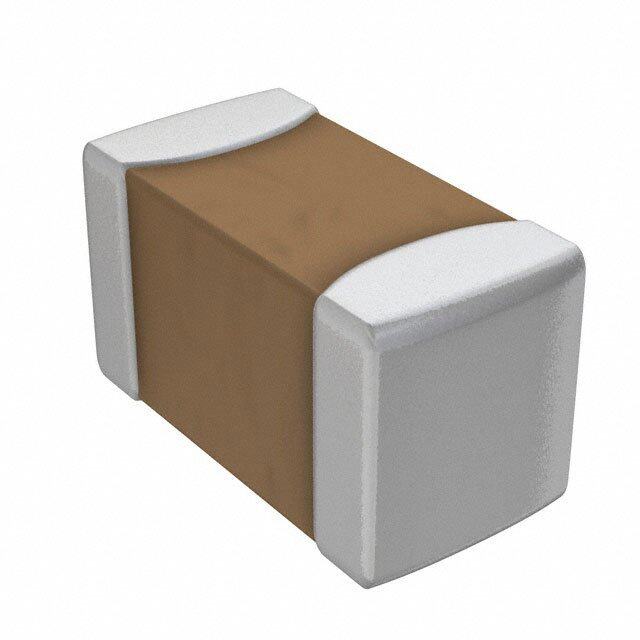
| LED大小 | 1.6 mm x 0.8 mm |
| 品牌 | Seoul Semiconductor |
| 产品目录 | 光电子产品 |
| 描述 | 标准LED-SMD Red, 660nm 80mcd, 20mA |
| 产品分类 | LED照明 |
| 产品手册 | http://www.acriche.com/en/product/prd/chipLED.asp |
| 产品图片 |
|
| rohs | 符合RoHS |
| 产品系列 | LED发射器,标准LED-SMD,Seoul Semiconductor UR101 |
| 产品型号 | UR101 |
| 产品种类 | 标准LED-SMD |
| 光强度 | 80 mcd |
| 商标 | Seoul Semiconductor |
| 封装 | Reel |
| 封装/箱体 | 1608 |
| 工厂包装数量 | 4000 |
| 显示角 | 120 deg |
| 最大工作温度 | + 85 C |
| 最小工作温度 | - 30 C |
| 正向电压 | 2.1 V |
| 正向电流 | 20 mA |
| 波长/色温 | 660 nm |
| 照明颜色 | Red |


- 商务部:美国ITC正式对集成电路等产品启动337调查
- 曝三星4nm工艺存在良率问题 高通将骁龙8 Gen1或转产台积电
- 太阳诱电将投资9.5亿元在常州建新厂生产MLCC 预计2023年完工
- 英特尔发布欧洲新工厂建设计划 深化IDM 2.0 战略
- 台积电先进制程称霸业界 有大客户加持明年业绩稳了
- 达到5530亿美元!SIA预计今年全球半导体销售额将创下新高
- 英特尔拟将自动驾驶子公司Mobileye上市 估值或超500亿美元
- 三星加码芯片和SET,合并消费电子和移动部门,撤换高东真等 CEO
- 三星电子宣布重大人事变动 还合并消费电子和移动部门
- 海关总署:前11个月进口集成电路产品价值2.52万亿元 增长14.8%
PDF Datasheet 数据手册内容提取
T e c h n i c a Pb Free l D a t a S h e Specification e t UR101 SSC Customer Drawn Approval Approval RReevv.. 0022 JJaannuuaarryy 22001122 WWWWWW..SSEEOOUULLSSEEMMIICCOONN..CCOOMM 서식번호 : SSC- QP- 7- 07- 25 (Rev.0.0)
T e c h n i c a l D a t a [ Contents ] S h e e t 1. Description 2. Absolute maximum ratings 3. Electro-Optical characteristics 4. Characteristic diagrams 5. Reliability result 6. Rank 7. Outline Dimension 8. Material 9. Reel Structure 10. Packing 11. Soldering profile 12. Precaution for Use RReevv.. 0022 JJaannuuaarryy 22001122 WWWWWW..SSEEOOUULLSSEEMMIICCOONN..CCOOMM 서식번호 : SSC- QP- 7- 07- 25 (Rev.0.0)
T e c h n i c a l D UR101 UR101 a t a S h 1. Description Features e e t - Small size suitable for compact • 1.6 X 0.8 X 0.8 mm appliances. • Untinted, Diffused flat - Surface-mounted chip LED mold device. • Peak Wavelength : 660nm - Pb-free and RoHS complaint component. - High brightness, High efficiency - Tape and Reel packing. Applications - Increases the life time of battery. (cid:1) Cellular phone’s keypad lightning (cid:1) Information Boards RReevv.. 0022 JJaannuuaarryy 22001122 WWWWWW..SSEEOOUULLSSEEMMIICCOONN..CCOOMM 서식번호 : SSC- QP- 7- 07- 25 (Rev.0.0)
T e c h n i c a l 2. Absolute maximum ratings D a (Ta=25℃℃℃℃) t a Parameter Symbol Value Unit S h e Power Dissipation P 61.5 mW d e t Forward Current I 30 mA F Peak Forward Current I *1 100 mA FM Reverse Voltage V 5 V R Operating Temperature T -40 ~ 85 ℃ opr. Storage Temperature T -40 ~ 100 ℃ stg. *1 I conditions: Pulse width Tw≤1msec and Duty ratio≤1/10. FM 3. Electro-Optical Characteristics (Ta=25℃℃℃℃) Parameter Symbol Condition Min Typ Max Unit Forward Voltage V I =20㎃ 1.7 1.9 2.05 V F F Reverse Current I V =5V - - 10 uA R R Luminous Intensity*2 Iv I =20㎃ 45 85 125 mcd F Wavelength λ I =20㎃ 650 660 668 nm p F Spectral Bandwidth Δλ I =20㎃ - 20 - nm F Viewing Angle*3 (Y) 2θ I =20㎃ - 156 - ˚ 1/2 F *2 The luminous intensity IV is measured at the peak of the spatial pattern which may not be aligned with the mechanical axis of the LED package. *3 θ1/2 is the off-axis where the luminous intensity is 1/2 the peak intensity. [Note] All measurements were made under the standardized environment of SSC. (Tolerance : I ±10 %, λ ±2 nm, V ±0.1 V) v d F RReevv.. 0022 JJaannuuaarryy 22001122 WWWWWW..SSEEOOUULLSSEEMMIICCOONN..CCOOMM 서식번호 : SSC- QP- 7- 07- 25 (Rev.0.0)
T e c h n i c a l 4. Characteristic Diagrams D a Ta = 25o t a S h Forward Current vs. Relative Luminous Intensity vs. e Forward Voltage Forward Current e t 30 1.6 1.4 25 u.] a. mA] 20 nsity [ 1.2 nt [ nte 1.0 Curre 15 nous I 0.8 d mi ar u 0.6 w 10 L or e F ativ 0.4 5 Rel 0.2 0 0.0 1.6 1.7 1.8 1.9 2.0 0 5 10 15 20 25 30 Forward Voltage [V] Forward Current [mA] Forward Current vs. Spectrum Ambient Temperature 35 1.0 30 u.] a. mA] 25 sity [ 0.8 ent [ 20 nten 0.6 Curr 15 on I d ssi 0.4 ar mi rw 10 E Fo e 0.2 v 5 ati el R 0.0 400 500 600 700 0 -25 0 25 50 75 100 Ambient Temperature [℃] Wavelength [nm] RReevv.. 0022 JJaannuuaarryy 22001122 WWWWWW..SSEEOOUULLSSEEMMIICCOONN..CCOOMM 서식번호 : SSC- QP- 7- 07- 25 (Rev.0.0)
T e c h n i c a l D Radiation Diagram a Ta = 25o t a 90 S h 120 60 e e t 150 30 180 0 X Y RReevv.. 0022 JJaannuuaarryy 22001122 WWWWWW..SSEEOOUULLSSEEMMIICCOONN..CCOOMM 서식번호 : SSC- QP- 7- 07- 25 (Rev.0.0)
T e c h n i c a l 5. Reliability Test D a t a S Duration Number Of Item Test Conditions h / Cycle Damaged e e t Operating at Room 20mA, @25℃ 500 hrs 0/22 temperature Operating at High 20mA, @85℃ 500 hrs 0/22 temperature Operating at High temperature 20mA, @60℃,90% 500 hrs 0/22 / High humidity Thermal shock test -40~85℃ Shift (2hr/cycle) 100 cycle 0/22 85℃, 85% 24hrs (cid:2) Reflow 3 times Thermal resistance (Max 260℃ 10sec) (cid:2) Thermal shock 1 time 0/22 Test 30 cycle MSL : 2a (30℃, 60% : 4 weeks) *Criterion OK Iv > Initial value * 0.5 V Initial value ± 0.1V F RReevv.. 0022 JJaannuuaarryy 22001122 WWWWWW..SSEEOOUULLSSEEMMIICCOONN..CCOOMM 서식번호 : SSC- QP- 7- 07- 25 (Rev.0.0)
T e c h n i c a l 6. Rank D a I = 20mA F t a BIN I [mcd] V [V] W [nm] S V F P h e A 45-85 1.7-2.05 650-668 e t B 85-125 1.7-2.05 650-668 RReevv.. 0022 JJaannuuaarryy 22001122 WWWWWW..SSEEOOUULLSSEEMMIICCOONN..CCOOMM 서식번호 : SSC- QP- 7- 07- 25 (Rev.0.0)
T e c h n i c a l 7. Outline Dimension D a t Tolerance ±0.1, Unit : ㎜ a S h e 0.18 3 e 0. Polarity Mark t Resin Polarity Mark Cathode 6 2 1 1. 1. 1. PCB Anode 0.8 0.4±0.05 3 0. 8 4 . . 0 2 0.8 [Recommended Solder Pattern] 8. Material Item Substrate chip wire Encapsulate Electrode Material BT-Resin PCB AlGaAs Gold Epoxy Au Plated RReevv.. 0022 JJaannuuaarryy 22001122 WWWWWW..SSEEOOUULLSSEEMMIICCOONN..CCOOMM 서식번호 : SSC- QP- 7- 07- 25 (Rev.0.0)
T e c h n i c a l 9. Reel Structure D a t a S h e e t (1) Quantity : 4000pcs/Reel (2) Cumulative Tolerance : Cumulative Tolerance/10 pitches to be ±0.2mm (3) Adhesion Strength of Cover Tape : Adhesion strength to be 0.1-0.7N when the cover tape is turned off from the carrier tape at 10℃ angle to be the carrier tape (4) Package : P/N, Manufacturing data Code No. and quantity to be indicated on a damp proof Package RReevv.. 0022 JJaannuuaarryy 22001122 WWWWWW..SSEEOOUULLSSEEMMIICCOONN..CCOOMM 서식번호 : SSC- QP- 7- 07- 25 (Rev.0.0)
T e c h n i c a l 10. Packing D a t Reel a S RANK: h XXX e e QUANTITY : XXXX t LOT NUMBER : XXXXXXXXXX PART NUMBER : XXXXXX SEOUL SEMICONDUCTOR CO., LTD. HUMIDITY INDICATOR #### Aluminum Vinyl Bag ### DESI PAK ### ### RANK: ####### XXX QUANTITY : XXXX LOT NUMBER : XXXXXXXXXX PART NUMBER : XXXXXX SEOUL SEMICONDUCTOR CO., LTD. Outer Box Structure 1 SIDE RANK: QUANTITY : XXXX c LOT NUMBER : XXXXXXXXXX 1 PART NUMBER : XXXXXX 2 SEOUL SEMICONDUCTOR CO., LTD. RoHS b 2 SIDE a LOT NUMBER Rank QTY Material : Paper(SW3B(B)) SIZE (mm) TYPE a b c 7inch 245 220 142 SEOUL SEMICONDUCTOR CO., LTD. RReevv.. 0022 JJaannuuaarryy 22001122 WWWWWW..SSEEOOUULLSSEEMMIICCOONN..CCOOMM 서식번호 : SSC- QP- 7- 07- 25 (Rev.0.0)
T e c h n i c a l 11. Soldering profile D a t a S (1) Lead Solder h e e t Lead Solder Lead Solder Pre-heat 120~150℃℃℃℃ 2.5~5 o C / sec. 240 oC Max. 10 sec. Max. Pre-heat time 120 sec. Max. Pre-heating o 60sec. Max. 120~150 C 2.5~5 C / sec. o Peak-Temperature 240℃℃℃℃ Max. Above 200 C Soldering time 10 sec. Max. 120sec. Max. Condition (2) Lead-Free Solder Lead Free Solder Lead-frame Solder Pre-heat 150~200℃℃℃℃ 1~5 o C / sec. 260 oC Max. 10 sec. Max. Pre-heat time 120 sec. Max. Pre-heating 1~5 o C / sec. 150~200 oC 60sec. Maxo. Peak-Temperature 260℃℃℃℃ Max. Above 220 C Soldering time 10 sec. Max. 120sec. Max. Condition (3) Hand Soldering conditions Do not exceed 3 seconds at maximum 280ºC under soldering iron. Note : In case that the soldered products are reused in soldering process, we don’t guarantee the products. RReevv.. 0022 JJaannuuaarryy 22001122 WWWWWW..SSEEOOUULLSSEEMMIICCOONN..CCOOMM 서식번호 : SSC- QP- 7- 07- 25 (Rev.0.0)
T e c h n i c a l 12. Precaution for Use D a (1) Storage t LEDs must be stored at clean atmosphere. If the LEDs are stored for 3 months or more a after shipment from SSC, storage in a sealed container with a nitrogen atmosphere is S recommended. To avoid absorption of moisture, it is recommended to store in a dry box h e (or a desiccator) with a desiccant. e * Shelf Life : 12 months at < 40ºC and 90%RH t (2) Attention after open. LED is correspond to SMD, when LED be soldered dip, interfacial separation may affect the light transmission efficiency, causing the light intensity to drop. After opened and mounted the soldering shall be quickly. * Within 672 hours at factory conditions of equal to or less than 30ºC/60%RH, or Stored at < 10% RH (3) Repack unused products with anti-moisture packing, fold to close any opening and then store in a dry place. (4) In the case of change color of indicator on desiccant, components shall be dried 10-12hr at 60±5ºC. (5) When the LED is operating, the driving current should be determined after considering the maximum ambient temperature requirements. (6) When using multiple LEDs, It is recommended to connect a resistor on each LED. Otherwise, LEDs may vary due to variation in forward voltage of the LEDs. (7) The driving circuit must be designed to allow forward voltage only when it is ON or OFF. If the reverse voltage is applied to LED, migration can be generated resulting in LED damage (8) Any mechanical force or excessive vibration should be avoided during temperature cooling process to normal temperature after reflow. (9) Rapid cooling shall be avoided. (10) LED should not be placed on a flexible area on the PCB. (11) This device should not be used in any type of fluid such as water, oil, organic solvent etc. When washing is required, IPA should be used. (12) Anti radioactive ray design is not considered for the products. (13) Damage prevention from ESD or Surge. It is highly recommended to use the wrist-band or anti electrostatic gloves when handling the LED’s All devices, equipments and machines mush be properly grounded (14) The appearance and specifications of the product may be modified for improvement without notice. RReevv.. 0022 JJaannuuaarryy 22001122 WWWWWW..SSEEOOUULLSSEEMMIICCOONN..CCOOMM 서식번호 : SSC- QP- 7- 07- 25 (Rev.0.0)
Mouser Electronics Authorized Distributor Click to View Pricing, Inventory, Delivery & Lifecycle Information: S eoul Semiconductor: UR101