ICGOO在线商城 > 集成电路(IC) > 数据采集 - 数模转换器 > AD565AJD
 Datasheet下载
- 型号: AD565AJD
- 制造商: Analog
- 库位|库存: xxxx|xxxx
- 要求:
| 数量阶梯 | 香港交货 | 国内含税 |
| +xxxx | $xxxx | ¥xxxx |
查看当月历史价格
查看今年历史价格
AD565AJD产品简介:
ICGOO电子元器件商城为您提供AD565AJD由Analog设计生产,在icgoo商城现货销售,并且可以通过原厂、代理商等渠道进行代购。 AD565AJD价格参考¥230.98-¥452.62。AnalogAD565AJD封装/规格:数据采集 - 数模转换器, 12 位 数模转换器 1 24-CDIP。您可以下载AD565AJD参考资料、Datasheet数据手册功能说明书,资料中有AD565AJD 详细功能的应用电路图电压和使用方法及教程。
AD565AJD 是 Analog Devices Inc. 生产的一款数模转换器 (DAC),属于数据采集系统中的关键组件。它主要用于将数字信号转换为模拟信号,广泛应用于各种需要高精度、低功耗和快速响应的场景中。

 应用场景:

1. 工业自动化与控制:
   AD565AJD 在工业自动化领域中常用于精密控制和测量系统。例如,在温度、压力、流量等传感器的数据采集过程中,它能够将传感器输出的数字信号转换为模拟信号,以便驱动执行器或进行进一步的处理。其高精度和稳定性使得它在工业控制系统中表现出色。

2. 通信设备:
   在通信设备中,AD565AJD 可用于信号调制和解调。它能够将数字基带信号转换为模拟射频信号,适用于无线通信、卫星通信等领域。其低功耗特性使其在便携式通信设备中也具有广泛应用。

3. 医疗设备:
   医疗设备如心电图机、超声波设备等需要高精度的信号转换。AD565AJD 的高分辨率和低噪声特性使其非常适合这些应用场景。它可以将来自传感器的数字信号转换为模拟信号,以供医生进行诊断和分析。

4. 音频处理:
   在音频处理设备中,AD565AJD 可用于将数字音频信号转换为模拟音频信号,适用于音响设备、耳机放大器等。其优异的线性度和低失真特性确保了音频信号的质量。

5. 测试与测量仪器:
   测试与测量仪器如示波器、信号发生器等需要高精度的信号转换。AD565AJD 可以提供稳定的模拟输出,帮助工程师进行精确的测量和分析。

6. 消费电子:
   在消费电子产品中,AD565AJD 也可用于智能家居设备、可穿戴设备等。它的小尺寸和低功耗特性使其适合集成到小型化的产品中,同时保证了信号转换的精度。

总之,AD565AJD 凭借其高精度、低功耗和快速响应的特点,在多个行业中都有广泛的应用,特别是在对信号转换要求较高的场合中表现尤为突出。
| 参数 | 数值 |
| 产品目录 | 集成电路 (IC)半导体 |
| 描述 | IC DAC 12BIT MONO HS 24-CDIP数模转换器- DAC IC MONO 12-BIT |
| 产品分类 | |
| 品牌 | Analog Devices |
| 产品手册 | |
| 产品图片 |
|
| rohs | 否不符合限制有害物质指令(RoHS)规范要求 |
| 产品系列 | 数据转换器IC,数模转换器- DAC,Analog Devices AD565AJD- |
| 数据手册 | |
| 产品型号 | AD565AJD |
| 产品培训模块 | http://www.digikey.cn/PTM/IndividualPTM.page?site=cn&lang=zhs&ptm=19145http://www.digikey.cn/PTM/IndividualPTM.page?site=cn&lang=zhs&ptm=18614http://www.digikey.cn/PTM/IndividualPTM.page?site=cn&lang=zhs&ptm=26125http://www.digikey.cn/PTM/IndividualPTM.page?site=cn&lang=zhs&ptm=26140http://www.digikey.cn/PTM/IndividualPTM.page?site=cn&lang=zhs&ptm=26150http://www.digikey.cn/PTM/IndividualPTM.page?site=cn&lang=zhs&ptm=26147 |
| 产品种类 | 数模转换器- DAC |
| 位数 | 12 |
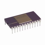
| 供应商器件封装 | 24-CDIP 侧面镀铜 |
| 分辨率 | 12 bit |
| 包装 | 管件 |
| 商标 | Analog Devices |
| 安装类型 | 通孔 |
| 安装风格 | Through Hole |
| 封装 | Tube |
| 封装/外壳 | 24-CDIP(0.600",15.24mm) |
| 封装/箱体 | CDIP-24 SB |
| 工作温度 | 0°C ~ 70°C |
| 工厂包装数量 | 15 |
| 建立时间 | 250ns |
| 接口类型 | Parallel |
| 数据接口 | 并联 |
| 最大功率耗散 | 345 mW |
| 最大工作温度 | + 70 C |
| 最小工作温度 | 0 C |
| 标准包装 | 15 |
| 电压参考 | Internal, External |
| 电压源 | 单电源 |
| 电源电压-最大 | 16.5 V |
| 电源电压-最小 | 11.4 V |
| 积分非线性 | +/- 0.75 LSB |
| 稳定时间 | 250 ns |
| 系列 | AD565A |
| 结构 | Current Steering |
| 转换器数 | 1 |
| 转换器数量 | 1 |
| 输出数和类型 | 1 电流,单极1 电流,双极 |
| 输出类型 | Analog |
| 采样率(每秒) | - |


- 商务部:美国ITC正式对集成电路等产品启动337调查
- 曝三星4nm工艺存在良率问题 高通将骁龙8 Gen1或转产台积电
- 太阳诱电将投资9.5亿元在常州建新厂生产MLCC 预计2023年完工
- 英特尔发布欧洲新工厂建设计划 深化IDM 2.0 战略
- 台积电先进制程称霸业界 有大客户加持明年业绩稳了
- 达到5530亿美元!SIA预计今年全球半导体销售额将创下新高
- 英特尔拟将自动驾驶子公司Mobileye上市 估值或超500亿美元
- 三星加码芯片和SET,合并消费电子和移动部门,撤换高东真等 CEO
- 三星电子宣布重大人事变动 还合并消费电子和移动部门
- 海关总署:前11个月进口集成电路产品价值2.52万亿元 增长14.8%


PDF Datasheet 数据手册内容提取
a High Speed 12-Bit Monolithic D/A Converters AD565A/AD566A FEATURES FUNCTIONAL BLOCK DIAGRAMS Single Chip Construction REF OUT VCC BIPOLAR OFF Very High Speed Settling to 1/2 LSB AD565A: 250 ns max 20V SPAN AD566A: 350 ns max 10V AD565A 5k(cid:1) Full-Scale Switching Time: 30 ns REF 19.95k(cid:1) 0.5mA 9.95k(cid:1) 10V SPAN Guaranteed for Operation with (cid:3)12 V (565A) Supplies, IN 5k(cid:1) IREF with –12 V Supply (AD566A) DAC DAC OUT Linearity Guaranteed Overtemperature GRNEDF 20k(cid:1) I4O (cid:2)UT I R=EF (cid:2) CODE IO 8k(cid:1) 1/2 LSB max (K, T Grades) CODE INPUT Monotonicity Guaranteed Overtemperature Low Power: AD566A = 180 mW max; AD565A = 225 mW max –VEE POGWNDER MSB LBSIPBOLAR OFF Use with On-Board High Stability Reference (AD565A) or with External Reference (AD566A) 20V SPAN AD566A Low Cost 9.95k(cid:1) 5k(cid:1) MlL-STD-883-Compliant Versions Available REF 19.95k(cid:1) 0.5mA 10V SPAN IN 5k(cid:1) IREF PRODUCT DESCRIPTION DAC DAC OUT The AD565A and AD566A are fast 12-bit digital-to-analog GRNEDF 20k(cid:1) I4O (cid:2)UT I R=EF (cid:2) CODE IO 8k(cid:1) converters that incorporate the latest advances in analog circuit CODE INPUT design to achieve high speeds at low cost. The AD565A and AD566A use 12 precision, high speed bipolar –VEE POWER MSB LSB current-steering switches, a control amplifier, and a laser-trimmed GND thin-film resistor network to produce a very fast, high accuracy AD565A and AD566A are available in four performance analog output current. The AD565A also includes a buried grades. The J and K grades are specified for use over the 0°C to Zener reference that features low noise, long-term stability, and +70°C temperature range while the S and T grades are speci- temperature drift characteristics comparable to the best discrete fied for the –55°C to +125°C range. The D grades are all pack- reference diodes. aged in a 24-lead, hermetically sealed, ceramic, dual-in-line The combination of performance and flexibility in the AD565A and package. The JR grade is packaged in a 28-lead plastic SOIC. AD566A has resulted from major innovations in circuit design, PRODUCT HIGHLIGHTS an important new high speed bipolar process, and continuing 1. The wide output compliance range of the AD565A and advances in laser-wafer-trimming techniques (LWT). The AD566A are ideally suited for fast, low noise, accurate voltage AD565A and AD566A have a 10%–90% full-scale transition output configurations without an output amplifier. time less than 35 ns and settle to within ±1/2 LSB in 250 ns max 2. The devices incorporate a newly developed, fully differential, (350 ns for AD566A). Both are laser-trimmed at the wafer level to ±1/8 LSB typical linearity and are specified to ±1/4 LSB max nonsaturating precision current switching cell structure that error (K and T grades) at +25°C. High speed and accuracy make combines the dc accuracy and stability first developed in the AD562/AD563 with very fast switching times and an optimally the AD565A and AD566A the ideal choice for high speed display damped settling characteristic. drivers as well as for fast analog-to-digital converters. 3. The devices also contain SiCr thin-film application resistors The laser trimming process that provides the excellent linearity that can be used with an external op amp to provide a preci- is also used to trim both the absolute value and the temperature sion voltage output or as input resistors for a successive- coefficient of the reference of the AD565A, resulting in a typical full-scale gain TC of 10 ppm/°C. When tighter TC performance approximation A/D converter. The resistors are matched to the internal ladder network to guarantee a low gain temperature is required or when a system reference is available, the AD566A coefficient and are laser-trimmed for minimum full-scale and may be used with an external reference. bipolar offset errors. 4. The AD565A and AD566A are available in versions compliant with MIL-STD-883. Refer to the Analog Devices Military Products Databook or current /883B data sheet for detailed REV. E specifications. Information furnished by Analog Devices is believed to be accurate and reliable. However, no responsibility is assumed by Analog Devices for its use, nor for any infringements of patents or other rights of third parties that One Technology Way, P.O. Box 9106, Norwood, MA 02062-9106, U.S.A. may result from its use. No license is granted by implication or otherwise Tel: 781/329-4700 www.analog.com under any patent or patent rights of Analog Devices. Fax: 781/326-8703 © Analog Devices, Inc., 2002
AD565A–SPECIFICATIONS (T = 25(cid:4)C, V = 15 V, V = 15 V, unless otherwise noted.) A CC EE AD565AJ AD565AK Parameter Min Typ Max Min Typ Max Unit DATA INPUTS1 (Pins 13 to 24) TTL or 5 V CMOS Input Voltage Bit ON Logic “1” 2.0 5.5 2.0 5.5 V Bit OFF Logic “0” 0.8 0.8 V Logic Current (Each Bit) Bit ON Logic “1” 120 300 120 300 µA Bit OFF Logic “0” 35 100 35 100 µA RESOLUTION 12 12 Bits OUTPUT Current Unipolar (All Bits On) –1.6 –2.0 –2.4 –1.6 –2.0 –2.4 mA Bipolar (All Bits On or Off) (cid:3)0.8 ±1.0 (cid:3)1.2 (cid:3)0.8 ±1.0 (cid:3)1.2 mA Resistance (Exclusive of Span Resistors) 6 8 10 6 8 10 kΩ Offset Unipolar 0.01 0.05 0.01 0.05 % of F.S. Range Bipolar (Figure 3, R2 = 50 Ω Fixed) 0.05 0.15 0.05 0.1 % of F.S. Range Capacitance 25 25 pF Compliance Voltage T to T –1.5 +10 –1.5 +10 V MIN MAX ACCURACY (Error Relative to Full Scale) 25°C ±1/4 (cid:3)1/2 ±1/8 (cid:3)0.35 LSB (0.006) (0.012) (0.003) (0.0084) % of F.S. Range T to T ±1/2 (cid:3)3/4 ±1/4 (cid:3)1/2 LSB MIN MAX (0.012) (0.018) (0.006) (0.012) % of F.S. Range DIFFERENTIAL NONLINEARITY 25°C ±1/2 (cid:3)3/4 ±1/4 (cid:3)1/2 LSB T to T MONOTONICITY GUARANTEED MONOTONICITY GUARANTEED MIN MAX TEMPERATURE COEFFICIENTS With Internal Reference Unipolar Zero 1 2 1 2 ppm/°C Bipolar Zero 5 10 5 10 ppm/°C Gain (Full Scale) 15 50 10 20 ppm/°C Differential Nonlinearity 2 2 ppm/°C SETTLING TIME TO 1/2 LSB All Bits ON-to-OFF or OFF-to-ON 250 400 250 400 ns FULL-SCALE TRANSITION 10% to 90% Delay plus Rise Time 15 30 15 30 ns 90% to 10% Delay plus Fall Time 30 50 30 50 ns TEMPERATURE RANGE Operating 0 +70 0 +70 °C Storage –65 +150 –65 +150 °C POWER REQUIREMENTS V , +11.4 to +16.5 V dc 3 5 3 5 mA CC V , –11.4 to –16.5 V dc –12 –18 –12 –18 mA EE POWER SUPPLY GAIN SENSITIVITY2 V = +11.4 to +16.5 V dc 3 10 3 10 ppm of F.S./% CC V = –11.4 to –16.5 V dc 15 25 15 25 ppm of F.S./% EE PROGRAMMABLE OUTPUT RANGES (See Figures 2, 3, 4) 0 to +5 0 to +5 V –2.5 to +2.5 –2.5 to +2.5 V 0 to +10 0 to +10 V –5 to +5 –5 to +5 V –10 to +10 –10 to +10 V EXTERNAL ADJUSTMENTS Gain Error with Fixed 50 Ω Resistor for R2 (Figure 2) ±0.1 (cid:3)0.25 ±0.1 (cid:3)0.25 % of F.S. Range Bipolar Zero Error with Fixed 50 Ω Resistor for R1 (Figure 3) ±0.05 (cid:3)0.15 ±0.05 ±0.1 % of F.S. Range Gain Adjustment Range (Figure 2) ±0.25 ±0.25 % of F.S. Range Bipolar Zero Adjustment Range ±0.15 ±0.15 % of F.S. Range REFERENCE INPUT Input Impedance 15 20 25 15 20 25 kΩ REFERENCE OUTPUT Voltage 9.90 10.00 10.10 9.90 10.00 10.10 V Current (Available for External Loads)3 1.5 2.5 1.5 2.5 mA POWER DISSIPATION 225 345 225 345 mW NOTES 1The digital inputs are guaranteed but not tested over the operating temperature range. 2The power supply gain sensitivity is tested in reference to a V , V of ±15 V dc. CC EE 3For operation at elevated temperatures, the reference cannot supply current for external loads. It, therefore, should be buffered if additional loads are to be supplied. Specifications subject to change without notice. –2– REV. E
AD565A/AD566A AD565AS AD565AT Parameter Min Typ Max Min Typ Max Unit DATA INPUTS1 (Pins 13 to 24) TTL or 5 V CMOS Input Voltage Bit ON Logic “1” 2.0 5.5 2.0 5.5 V Bit OFF Logic “0” 0.8 0.8 V Logic Current (Each Bit) Bit ON Logic “1” 120 300 120 300 µA Bit OFF Logic “0” 35 100 35 100 µA RESOLUTION 12 12 Bits OUTPUT Current Unipolar (All Bits On) –1.6 –2.0 –2.4 –1.6 –2.0 –2.4 mA Bipolar (All Bits On or Off) (cid:3)0.8 ±1.0 (cid:3)1.2 (cid:3)0.8 ±1.0 (cid:3)1.2 mA Resistance (Exclusive of Span Resistors) 6 8 10 6 8 10 kΩ Offset Unipolar 0.01 0.05 0.01 0.05 % of F.S. Range Bipolar (Figure 3, R2 = 50 Ω Fixed) 0.05 0.15 0.05 0.1 % of F.S. Range Capacitance 25 25 pF Compliance Voltage T to T –1.5 +10 –1.5 +10 V MIN MAX ACCURACY (Error Relative to Full Scale) 25°C ±1/4 (cid:3)1/2 ±1/8 (cid:3)0.35 LSB (0.006) (0.012) (0.003) (0.0084) % of F.S. Range T to T ±1/2 (cid:3)3/4 ±1/4 (cid:3)1/2 LSB MIN MAX (0.012) (0.018) (0.006) (0.012) % of F.S. Range DIFFERENTIAL NONLINEARITY 25°C ±1/2 (cid:3)3/4 ±1/4 (cid:3)1/2 LSB T to T MONOTONICITY GUARANTEED MONOTONICITY GUARANTEED MIN MAX TEMPERATURE COEFFICIENTS With Internal Reference Unipolar Zero 1 2 1 2 ppm/°C Bipolar Zero 5 10 5 10 ppm/°C Gain (Full Scale) 15 30 10 15 ppm/°C Differential Nonlinearity 2 2 ppm/°C SETTLING TIME TO 1/2 LSB All Bits ON-to-OFF or OFF-to-ON 250 400 250 400 ns FULL-SCALE TRANSITION 10% to 90% Delay plus Rise Time 15 30 15 30 ns 90% to 10% Delay plus Fall Time 30 50 30 50 ns TEMPERATURE RANGE Operating –55 +125 –55 +125 °C Storage –65 +150 –65 +150 °C POWER REQUIREMENTS V , +11.4 to +16.5 V dc 3 5 3 5 mA CC V , –11.4 to –16.5 V dc –12 –18 –12 –18 mA EE POWER SUPPLY GAIN SENSITIVITY2 V = +11.4 to +16.5 V dc 3 10 3 10 ppm of F.S./% CC V = –11.4 to –16.5 V dc 15 25 15 25 ppm of F.S./% EE PROGRAMMABLE OUTPUT RANGES (See Figures 2, 3, 4) 0 to +5 0 to +5 V –2.5 to +2.5 –2.5 to +2.5 V 0 to +10 0 to +10 V –5 to +5 –5 to +5 V –10 to +10 –10 to +10 V EXTERNAL ADJUSTMENTS Gain Error with Fixed 50 Ω Resistor for R2 (Figure 2) ±0.1 (cid:3)0.25 ±0.1 (cid:3)0.25 % of F.S. Range Bipolar Zero Error with Fixed 50 Ω Resistor for R1 (Figure 3) ±0.05 (cid:3)0.15 ±0.05 (cid:3)0.1 % of F.S. Range Gain Adjustment Range (Figure 2) ±0.25 ±0.25 % of F.S. Range Bipolar Zero Adjustment Range ±0.15 ±0.15 % of F.S. Range REFERENCE INPUT Input Impedance 15 20 25 15 20 25 kΩ REFERENCE OUTPUT Voltage 9.90 10.00 10.10 9.90 10.00 10.10 V Current (Available for External Loads)3 1.5 2.5 1.5 2.5 mA POWER DISSIPATION 225 345 225 345 mW Specifications shown in boldface are tested on all production units at final electrical test. Results from those tests are used to calculate outgoing quality levels. All min and max specifications are guaranteed, although only those shown in boldface are tested on all production units. Specification subject to change without notice. REV. E –3–
AD566A–SPECIFICATIONS (T = 25(cid:4)C, V = –15 V, unless otherwise noted) A EE AD566AJ AD566AK Parameter Min Typ Max Min Typ Max Unit DATA INPUTS1 (Pins 13 to 24) TTL or 5 V CMOS Input Voltage Bit ON Logic “1” 2.0 5.5 2.0 5.5 V Bit OFF Logic “0” 0 0.8 0 0.8 V Logic Current (Each Bit) Bit ON Logic “1” 120 300 120 300 µA Bit OFF Logic “0” 35 100 35 100 µA RESOLUTION 12 12 Bits OUTPUT Current Unipolar (All Bits On) –1.6 –2.0 –2.4 –1.6 –2.0 –2.4 mA Bipolar (All Bits On or Off) (cid:3)0.8 ±1.0 (cid:3)1.2 (cid:3)0.8 ±1.0 (cid:3)1.2 mA Resistance (Exclusive of Span Resistors) 6 8 10 6 8 10 kΩ Offset Unipolar (Adjustable to Zero per Figure 3) 0.01 0.05 0.01 0.05 % of F.S. Range Bipolar (Figure 4, R1 and R2 = 50 Ω Fixed) 0.05 0.15 0.05 0.1 % of F.S. Range Capacitance 25 25 pF Compliance Voltage T to T –1.5 +10 –1.5 +10 V MIN MAX ACCURACY (Error Relative to Full Scale) 25°C ±1/4 (cid:3)1/2 ±1/8 (cid:3)0.35 LSB (0.006) (0.012) (0.003) (0.0084) % of F.S. Range T to T ±1/2 (cid:3)3/4 ±1/4 (cid:3)1/2 LSB MIN MAX (0.012) (0.018) (0.006) (0.012) % of F.S. Range DIFFERENTIAL NONLINEARITY 25°C ±1/2 (cid:3)3/4 ±1/4 (cid:3)1/2 LSB T to T MONOTONICITY GUARANTEED MONOTONICITY GUARANTEED MIN MAX TEMPERATURE COEFFICIENTS Unipolar Zero 1 2 1 2 ppm/°C Bipolar Zero 5 10 5 10 ppm/°C Gain (Full Scale) 7 10 3 5 ppm/°C Differential Nonlinearity 2 2 ppm/°C SETTLING TIME TO 1/2 LSB All Bits ON-to-OFF or OFF-to-ON 250 350 250 350 ns FULL-SCALE TRANSITION 10% to 90% Delay plus Rise Time 15 30 15 30 ns 90% to 10% Delay plus Fall Time 30 50 30 50 ns POWER REQUIREMENTS V , –11.4 to –16.5 V dc –12 –18 –12 –18 mA EE POWER SUPPLY GAIN SENSITIVITY2 V = –11.4 to –16.5 V dc 15 25 15 25 ppm of F.S./% EE PROGRAMMABLE OUTPUT RANGES (see Figures 3, 4, 5) 0 to +5 0 to +5 V –2.5 to +2.5 –2.5 to +2.5 V 0 to +10 0 to +10 V –5 to +5 –5 to +5 V –10 to +10 –10 to +10 V EXTERNAL ADJUSTMENTS Gain Error with Fixed 50 Ω Resistor for R2 (Figure 3) ±0.1 (cid:3)0.25 ±0.1 (cid:3)0.25 % of F.S. Range Bipolar Zero Error with Fixed 50 Ω Resistor for R1 (Figure 4) ±0.05 (cid:3)0.15 ±0.05 (cid:3)0.1 % of F.S. Range Gain Adjustment Range (Figure 3) ±0.25 ±0.25 % of F.S. Range Bipolar Zero Adjustment Range ±0.15 ±0.15 % of F.S. Range REFERENCE INPUT Input Impedance 15 20 25 15 20 25 kΩ POWER DISSIPATION 180 300 180 300 mW MULTIPLYING MODE PERFORMANCE (All Models) Quadrants Two (2): Bipolar Operation at Digital Input Only Reference Voltage 1 V to 10 V, Unipolar Accuracy 10 Bits (±0.05% of Reduced F.S.) for 1 V dc Reference Voltage Reference Feedthrough (Unipolar Mode, All Bits OFF, and 1 V to 10 V [p-p], Sine Wave Frequency for 1/2 LSB [p-p] Feedthrough) 40 kHz typ Output Slew Rate 10%–90% 5 mA/µs 90%–10% 1 mA/µs Output Settling Time (All Bits ON and a 0 V–10 V Step Change in Reference Voltage) 1.5 µs to 0.01% F.S. CONTROL AMPLIFIER Full Power Bandwidth 300 kHz Small-Signal Closed-Loop Bandwidth 1.8 MHz NOTES 1The digital input levels are guaranteed but not tested over the temperature range. 2The power supply gain sensitivity is tested in reference to a V of –1.5 V dc. EE Specifications subject to change without notice. –4– REV. E
AD565A/AD566A AD566AS AD566AT Parameter Min Typ Max Min Typ Max Unit DATA INPUTS1 (Pins 13 to 24) TTL or 5 V CMOS Input Voltage Bit ON Logic “1” 2.0 5.5 2.0 5.5 V Bit OFF Logic “0” 0 0.8 0 0.8 V Logic Current (Each Bit) Bit ON Logic “1” 120 300 +120 300 µA Bit OFF Logic “0” 35 100 +35 100 µA RESOLUTION 12 12 Bits OUTPUT Current Unipolar (All Bits On) –1.6 –2.0 –2.4 –1.6 –2.0 –2.4 mA Bipolar (All Bits On or Off) (cid:3)0.8 ±1.0 (cid:3)1.2 (cid:3)0.8 ±1.0 (cid:3)1.2 mA Resistance (Exclusive of Span Resistors) 6 8 10 6 8 10 kΩ Offset Unipolar (Adjustable to Zero per Figure 3) 0.01 0.05 0.01 0.05 % of F.S. Range Bipolar (Figure 4, R1 and R2 = 50 Ω Fixed) 0.05 0.15 0.05 0.1 % of F.S. Range Capacitance 25 25 pF Compliance Voltage T to T –1.5 +10 –1.5 +10 V MIN MAX ACCURACY (Error Relative to Full Scale) 25°C ±1/4 (cid:3)1/2 ±1/8 (cid:3)0.35 LSB (0.006) (0.012) (0.003) (0.0084) % of F.S. Range T to T ±1/2 (cid:3)3/4 ±1/4 (cid:3)1/2 LSB MIN MAX (0.012) (0.018) (0.006) (0.012) % of F.S. Range DIFFERENTIAL NONLINEARITY 25°C ±1/2 (cid:3)3/4 ±1/4 (cid:3)1/2 LSB T to T MONOTONICITY GUARANTEED MONOTONICITY GUARANTEED MIN MAX TEMPERATURE COEFFICIENTS Unipolar Zero 1 2 1 2 ppm/°C Bipolar Zero 5 10 5 10 ppm/°C Gain (Full Scale) 7 10 3 5 ppm/°C Differential Nonlinearity 2 2 ppm/°C SETTLING TIME TO 1/2 LSB All Bits ON-to-OFF or OFF-to-ON 250 350 250 350 ns FULL-SCALE TRANSITION 10% to 90% Delay plus Rise Time 15 30 15 30 ns 90% to 10% Delay plus Fall Time 30 50 30 50 ns POWER REQUIREMENTS V , –11.4 to –16.5 V dc –12 –18 –12 –18 mA EE POWER SUPPLY GAIN SENSITIVITY2 V = –11.4 to –16.5 V dc 15 25 15 25 ppm of F.S./% EE PROGRAMMABLE OUTPUT RANGES (see Figures 3, 4, 5) 0 to +5 0 to +5 V –2.5 to +2.5 –2.5 to +2.5 V 0 to +10 0 to +10 V –5 to +5 –5 to +5 V –10 to +10 –10 to +10 V EXTERNAL ADJUSTMENTS Gain Error with Fixed 50 Ω Resistor for R2 (Figure 3) ±0.1 (cid:3)0.25 ±0.1 (cid:3)0.25 % of F.S. Range Bipolar Zero Error with Fixed 50 Ω Resistor for R1 (Figure 4) ±0.05 (cid:3)0.15 ±0.05 (cid:3)0.1 % of F.S. Range Gain Adjustment Range (Figure 3) ±0.25 ±0.25 % of F.S. Range Bipolar Zero Adjustment Range ±0.15 ±0.15 % of F.S. Range REFERENCE INPUT Input Impedance 15 20 25 15 20 25 kΩ POWER DISSIPATION 180 300 180 300 mW MULTIPLYING MODE PERFORMANCE (All Models) Quadrants Two (2): Bipolar Operation at Digital Input Only Reference Voltage 1 V to 10 V, Unipolar Accuracy 10 Bits (±0.05% of Reduced F.S.) for 1 V dc Reference Voltage Reference Feedthrough (Unipolar Mode, All Bits OFF, and 1 V to 10 V [p-p], Sine Wave Frequency for l/2 LSB [p-p] Feedthrough) 40 kHz typ Output Slew Rate 10%–90% 5 mA/µs 90%–10% 1 mA/µs Output Settling Time (All Bits ON and a 0 V–10 V Step Change in Reference Voltage) 1.5 µs to 0.01% F.S. CONTROL AMPLIFIER Full Power Bandwidth 300 kHz Small-Signal Closed-Loop Bandwidth 1.8 MHz Specifications shown in boldface are tested on all production units at final electrical test. Results from those tests are used to calculate outgoing quality levels. All min and max specifications are guaranteed, although only those shown in boldface are tested on all production units. Specification subject to change without notice. REV. E –5–
AD565A/AD566A ABSOLUTE MAXIMUM RATINGS GROUNDING RULES V to Power Ground . . . . . . . . . . . . . . . . . . . . . 0 V to +18 V The AD565A and AD566A use separate reference and power CC V to Power Ground (AD565A) . . . . . . . . . . . . 0 V to –18 V grounds to allow optimum connections for low noise and high EE Voltage on DAC Output (Pin 9) . . . . . . . . . . . . –3 V to +12 V speed performance. These grounds should be tied together at one Digital Inputs (Pins 13 to 24) to point, usually the device power ground. The separate ground Power Ground . . . . . . . . . . . . . . . . . . . . . . –1.0 V to +7.0 V returns minimize current flow in low level signal paths. In this REF IN to Reference Ground . . . . . . . . . . . . . . . . . . . . ±12 V way, logic return currents are not summed into the same return Bipolar Offset to Reference Ground . . . . . . . . . . . . . . . ±12 V path with analog signals. 10 V Span R to Reference Ground . . . . . . . . . . . . . . . . ±12 V 20 V Span R to Reference Ground . . . . . . . . . . . . . . . . ±24 V REF OUT (AD565A) . . . . . Indefinite Short to Power Ground Momentary Short to V CC Power Dissipation . . . . . . . . . . . . . . . . . . . . . . . . . . 1000 mW AD565A ORDERING GUIDE Max Gain Linearity T.C. (ppm Temperature Error Max Package Model1 of F.S./°C) Range @ +25°C Options2 AD565AJD 50 0°C to +70°C ±1/2 LSB Ceramic (D-24) AD565AJR 50 0°C to +70°C ±1/2 LSB SOIC (RW-28) AD565AKD 20 0°C to +70°C ±1/4 LSB Ceramic (D-24) AD565ASD 30 –55°C to +125°C ±1/2 LSB Ceramic (D-24) AD565ATD 15 –55°C to +125°C ±1/4 LSB Ceramic (D-24) NOTES 1For details on grade and package offerings screened in accordance with MIL-STD-883, refer to the Analog Devices Military Products Databook or current/883B data sheet. 2D = Ceramic DIP, R = SOIC. AD566A ORDERING GUIDE Max Gain Linearity T.C. (ppm Temperature Error Max Package Model1 of F.S./°C) Range @ +25°C Option2 AD566AJD 10 0°C to +70°C ±1/2 LSB Ceramic (D-24 AD566AKD 3 0°C to +70°C ±1/4 LSB Ceramic (D-24) AD566ASD 10 –55°C to +125°C ±1/2 LSB Ceramic (D-24) AD566ATD 3 –55°C to +125°C ±1/4 LSB Ceramic (D-24) NOTES 1For details on grade and package offerings screened in accordance with MIL-STD-883, refer to the Analog Devices Military Products Databook or current/883B data sheet. 2D = Ceramic DIP. CAUTION ESD (electrostatic discharge) sensitive device. Electrostatic charges as high as 4000 V readily WARNING! accumulate on the human body and test equipment and can discharge without detection. Although the AD565A/AD566A features proprietary ESD protection circuitry, permanent damage may occur on devices subjected to high energy electrostatic discharges. Therefore, proper ESD precautions are ESD SENSITIVE DEVICE recommended to avoid performance degradation or loss of functionality. –6– REV.E
AD565A/AD566A PIN CONFIGURATIONS 24-Lead DIP 24-Lead DIP NC 1 24 BIT 1 IN (MSB) NC 1 24BIT 1 IN (MSB) NC 2 23 BIT 2 IN NC 2 23BIT 2 IN VCC 3 22 BIT 3 IN REF GND 3 22BIT 3 IN REF OUT (+10V ±1%) 4 21 BIT 4 IN AMP SUMMING JUNCTION 4 21BIT 4 IN REF GND 5 AD565A 20 BIT 5 IN REF V HI IN 5 AD566A 20BIT 5 IN REF IN 6 TOP VIEW 19 BIT 6 IN –VEE –15V IN (20mA) 6 TOP VIEW 19 BIT 6 IN –VEE 7 (Not to Scale)18 BIT 7 IN BIPOLAR OFFSET IN 7 (Not to Scale) 18BIT 7 IN BIPOLAR OFFSET IN 8 17 BIT 8 IN NC 8 17 BIT 8 IN DAC OUT (–2mA F.S.) 9 16 BIT 9 IN DAC OUT (–2mA F.S.) 9 16BIT 9 IN 10V SPAN R 10 15 BIT 10 IN 10V SPAN R 10 15BIT 10 IN 20V SPAN R 11 14 BIT 11 IN 20V SPAN R 11 14BIT 11 IN PWR GND 12 13 BIT 12 IN (LSB) PWR GND 12 13BIT 12 IN (LSB) NC = NO CONNECT NC = NO CONNECT 28-Lead SOIC NC 1 28 NC NC 2 27 BIT 1 (MSB) NC 3 26 BIT 2 VCC 4 25 BIT 3 REF OUT (10V) 5 24 BIT 4 REF GND 6 AD565A 23 BIT 5 REF IN 7 TOP VIEW 22 BIT 6 NC 8 (Not to Scale) 21 BIT 7 –VEE 9 20 BIT 8 BIPOLAR OFFSET IN 10 19 BIT 9 DAC OUT 11 18 BIT 10 NC 12 17 BIT 11 10V SPAN R 13 16 BIT 12 (LSB) 20V SPAN R 14 15 PWR GND NC = NO CONNECT REV. E –7–
AD565A/AD566A CONNECTING THE AD565A FOR BUFFERED VOLTAGE OUTPUT R1 The standard current-to-voltage conversion connections using an ROEUFT VCC 100(cid:1) BIPOLAR OFF operational amplifier are shown in Figures 1, 2, and 3 with the 20V SPAN preferred trimming techniques. If a low offset operational amplifier 5k(cid:1) 9.95k(cid:1) 10V SPAN (OP77, AD741L, OP07) is used, excellent performance can be R2 10V 100(cid:1) AD565A 5k(cid:1) obtained in many situations without trimming (an op amp with 10pF OUTPUT leersrso rtsh abne l0o.w5 1m/2V LmSaBx) .o Ifffs ae t5 v0olΩta gfiex esdh oruesldis tboer uiss esdu btost kiteuetpe do fffosert REF 19.95k(cid:1) 0I.R5EmFA DACIO 8k(cid:1) DOAUCT AD509 –+55VV TO ((th0pe.l2u 15s0 %o0p mΩ a amtxrpi)m. oSmfufesbres,t t)ui tnaunitpidno glfau arl lz5-es0croaΩl ie sr eatscyicpsutiocrara lcflyoy r wi sti htwhei it1nh0 i±0n1 Ω0/2 .1b L%ipSoB- GRNEDFIN 20k(cid:1) I 4O(cid:2) (cid:2)U CT I OR=EDFE 2.4k(cid:1) CODE lar offset trimmer gives a bipolar zero error typically within POWER INPUT ±2 LSB (0.05%). GND The AD509 is recommended for buffered voltage-output –VEE MSB LSB applications that require a settling time to ±1/2 LSB of 1 µs. The feedback capacitor is shown with the optimum value Figure 2. ±5 V Bipolar Voltage Output for each application; this capacitor is required to compen- sate for the 25 pF DAC output capacitance. STEP I . . . OFFSET ADJUST Turn OFF all bits. Adjust 100Ω trimmer R1 to give –5.000 V FIGURE 1. UNIPOLAR CONFIGURATION output. This configuration provides a unipolar 0 V to 10 V output range. In this mode, the bipolar terminal, Pin 8, should be STEP II . . . GAIN ADJUST grounded if not used for trimming. Turn ON all bits. Adjust 100Ω gain trimmer R2 to give a reading of +4.9976 V. +15V Please note that it is not necessary to trim the op amp to obtain 100k(cid:1) R1 50k(cid:1) full accuracy at room temperature. In most bipolar situations, 100(cid:1) an op amp trim is unnecessary unless the untrimmed offset drift –15V of the op amp is excessive. ROEUFT VCC BIPOLAR OFF FIGURE 3. OTHER VOLTAGE RANGES 20V SPAN 5k(cid:1) The AD565A can also be easily configured for a unipolar 0 V to R2 10V 9.95k(cid:1) 10V SPAN +5 V range or ±2.5 V and ±10 V bipolar ranges by using the 100(cid:1) AD565A 5k(cid:1) additional 5 kΩ application resistor provided at the 20 V span R 19.95k(cid:1) 0.5mA IO 8k(cid:1) DOAUCT 10pF O0+V1U0 TTVPOUT ttwerom 5in kaΩl, Preisni s1to1r.s F aorre au s5e dV isnp panar (a0ll eVl btoy s+h5o rVti,n ogr P±i2n. 51 1V t)o, tPhien 9 REINF IREF DAC AD509 and connecting Pin 10 to the op amp output and the bipolar GRNEDF 20k(cid:1) I4 O(cid:2) (cid:2)U CT I OR=EDFE 2.4k(cid:1) obfipfsoelta re iothffesre tt oe itghreoru tnod g frooru unndi pfoorl aurn oipr otloa rR oErF t oO RUETF fOorU tThe for CODE the bipolar range. For the ±10 V range (20 V span) use the 5 kΩ POWER INPUT GND resistors in series by connecting only Pin 11 to the op amp output –VEE MSB LSB and the bipolar offset connected as shown. The ±10 V option is shown in Figure 3. Figure 1.0 V to 10 V Unipolar Voltage Output STEP I . . . ZERO ADJUST R1 Turn all bits OFF and adjust zero trimmer R1 until the output ROEUFT VCC 100(cid:1) BIPOLAR OFF 20V SPAN reads 0.000 V (1 LSB = 2.44 mV). In most cases, this trim is not 5k(cid:1) needed, but Pin 8 should then be connected to Pin 12. 9.95k(cid:1) 10V SPAN R2 10V 100(cid:1) AD565A 5k(cid:1) STEP II . . . GAIN ADJUST 10pF OUTPUT Turn all bits ON and adjust 100Ω gain trimmer R2 until the 19.95k(cid:1) 0.5mA IO 8k(cid:1) DAC –10V TO OUT +10V output is 9.9976 V. (Full scale is adjusted to 1LSB less than REF IREF DAC AD509 IN n(eoxmacintlayl 2fu.5ll mscVa/leb iot)f, 1in0s.0er0t0 a V 1.2) 0IfΩ a r1e0s.i2st3o7r 5inV s feurilel ss cwailteh i st hdee sgiariend GRNEDF 20k(cid:1) I4 O(cid:2) (cid:2)U CT I OR=EDFE 3.0k(cid:1) resistor at Pin 10 to the op amp output. CODE POWER INPUT FIGURE 2. BIPOLAR CONFIGURATION GND This configuration provides a bipolar output voltage from –VEE MSB LSB –5.000 V to +4.9976 V, with positive full scale occurring with all bits ON (all 1s). Figure 3.±10 V Voltage Output –8– REV.E
AD565A/AD566A CONNECTING THE AD566A FOR BUFFERED VOLTAGE STEP II . . . GAIN ADJUST OUTPUT Turn all bits ON and adjust 100Ω gain trimmer, R2, until the The standard current-to-voltage conversion connections using an output is 9.9976 V. (Full scale is adjusted to 1 LSB less than operational amplifier are shown in Figures 4, 5, and 6 with the nominal full scale of 10.000 V.) If a 10.2375 V full scale is desired preferred trimming techniques. If a low offset operational amplifier (exactly 2.5 mV/bit), insert a 120Ω resistor in series with the (OP77, AD741L, OP07) is used, excellent performance can be gain resistor at Pin 10 to the op amp output. obtained in many situations without trimming (an op amp with less than 0.5 mV max offset voltage should be used to keep offset FIGURE 5. BIPOLAR CONFIGURATION errors below 1/2 LSB). If a 50Ω fixed resistor is substituted for the This configuration provides a bipolar output voltage from 100Ω trimmer, unipolar zero typically is within ±1/2 LSB (plus op –5.000 V to +4.9976 V, with positive full scale occurring with amp offset), and full-scale accuracy is within 0.1% (0.25% max). all bits ON (all 1s). Substituting a 50Ω resistor for the 100Ω bipolar offset trimmer gives a bipolar zero error typically within ±2 LSB (0.05%). The AD509 is recommended for buffered voltage-output R1 applications that require a settling time to ±1/2 LSB of 1 µs. The 100(cid:1) BIPOLAR OFF feedback capacitor is shown with the optimum value for each AD566A 20V SPAN application; this capacitor is required to compensate for the 9.95k(cid:1) 5k(cid:1) 25 pF DAC output capacitance. 10V SPAN R2 5k(cid:1) FIGURE 4. UNIPOLAR CONFIGURATION 100(cid:1) REF 10pF This configuration provides a unipolar 0 V to 10 V output range. IN 19.95k(cid:1) 0.5mA IO 8k(cid:1) DOAUCT Iuns etdhi sf omr otrdiem, mthien bgi.polar terminal, Pin 7, should be grounded if not +V 10VAERDE5F61 20k(cid:1) IREF I4OD (cid:2)UAT I R=CEF 2.4AkD(cid:1)509 REF (cid:2) CODE +15V GND CODE 100(cid:1) 100k(cid:1) R1 POWER INPUT 50k(cid:1) GND BIPOLAR OFF –15V –VEE MSB LSB 20V SPAN AD566A Figure 5.±5 V Bipolar Voltage Output 9.95k(cid:1) 5k(cid:1) 10V SPAN STEP I . . . OFFSET ADJUST 5k(cid:1) R2 REF 10pF Turn OFF all bits. Adjust 100Ω trimmer R1 to give –5.000 100(cid:1) IN 19.95k(cid:1) 0.5mA IO 8k(cid:1) DAC output V. OUT +V 10VAERDE5F61 20k(cid:1) IREF I4OD (cid:2)UAT I R=CEF 2.4AkD(cid:1)509 STTuErnP O IIN . a. l.l GbiAtsI. NA dAjDusJtU 1S0T0Ω gain trimmer R2 to give a read- REF (cid:2) CODE GND CODE ing of +4.9976 V. POWGNERD INPUT Please note that it is not necessary to trim the op amp to obtain full accuracy at room temperature. In most bipolar situations, –VEE MSB LSB an op amp trim is unnecessary unless the untrimmed offset drift of the op amp is excessive. Figure 4.0 V to 10 V Unipolar Voltage Output STEP I . . . ZERO ADJUST Turn all bits OFF and adjust zero trimmer, R1, until the output reads 0.000 V (1 LSB = 2.44 mV). In most cases, this trim is not needed, but Pin 7 should then be connected to Pin 12. REV. E –9–
AD565A/AD566A FIGURE 6. OTHER VOLTAGE RANGES The AD566A can also be easily configured for a unipolar 0 V to R1 +5 V range or ±2.5 V and ±10 V bipolar ranges by using the 5k(cid:1) BIPOLAR OFF additional 5 kΩ application resistor provided at the 20 V span R 20V SPAN terminal, Pin 11. For a 5 V span (0 V to +5 V or ±2.5V), the two AD566A 5 kΩ resistors are used in parallel by shorting Pin 11 to Pin 9 and 9.95k(cid:1) 5k(cid:1) 14k(cid:1) 10V SPAN connecting Pin 10 to the op amp output and the bipolar offset 10pF resistor either to ground for unipolar or to VREF for the bipolar 5Rk2(cid:1) REF 5k(cid:1) sraenrigees. bFyo cr otnhne e±c1ti0n gV o rnalnyg Pe i(n2 01 1V t sop tahne) ,o ups ea mthpe o5u ktΩpu rte asnisdto trhse in IN 19.95k(cid:1) 0.5mA IO 8k(cid:1) DOAUCT binip Foilgaur roef 6fs.et connected as shown. The ±10 V option is shown –V 7.5VAERDE5F61 20k(cid:1) IREF I4OD (cid:2)UAT I R=CEF 2.4kA(cid:1)D509 REF (cid:2) CODE GND CODE POWER INPUT R3 GND 26k(cid:1)* –VEE MSB LSB *THE PARALLEL COMBINATION OF THE BIPOLAR OFFSET RESISTOR AND R3 ESTABLISHES A CURRENT TO BALANCE THE MSB CURRENT. THE EFFECT OF TEMPERATURE COEFFICIENT MISMATCH BETWEEN THE BIPOLAR RESISTOR COMBINATION AND DAC RESISTORS IS EXPANDED ON PREVIOUS PAGE. Figure 6. ±10 V Voltage Output Table I. Digital Input Codes DIGITAL INPUT ANALOG OUTPUT MSB LSB Straight Binary Offset Binary Twos Complement* 0 0 0 0 0 0 0 0 0 0 0 0 Zero –FS Zero 0 1 1 1 1 1 1 1 1 1 1 1 Mid Scale – 1 LSB Zero – 1 LSB +FS – 1 LSB 1 0 0 0 0 0 0 0 0 0 0 0 +1/2 FS Zero –FS 1 1 1 1 1 1 1 1 1 1 1 1 +FS – l LSB +FS – 1 LSB Zero – 1 LSB *Inverts the MSB of the offset binary code with an external inverter to obtain twos complement. –10– REV.E
AD565A/AD566A OUTLINE DIMENSIONS 24-Lead Side-Brazed Solder Lid Ceramic DIP [DIP/SB] (D-24) Dimensions shown in inches and (millimeters) 0.005 (0.13) MIN 0.098 (2.49) MAX 24 13 0.610 (15.49) 0.500 (12.70) PIN 1 1 12 0.620 (15.75) 1.290 (32.77) MAX 0.075 (1.91) 0.590 (14.99) 0.225 (5.72) 0.015 (0.38) MAX 0.150 0.200 (5.08) (3.81) 0.120 (3.05) MIN 0.023 (0.58) 0.100 (2.54) 0.070 (1.78) SEATING 0.015 (0.38) 0.014 (0.36) BSC 0.030 (0.76) PLANE 0.008 (0.20) CONTROLLING DIMENSIONS ARE IN INCHES; MILLIMETER DIMENSIONS (IN PARENTHESES) ARE ROUNDED-OFF INCH EQUIVALENTS FOR REFERENCE ONLY AND ARE NOT APPROPRIATE FOR USE IN DESIGN 28-Lead Standard Small Outline Package [SOIC] Wide Body (RW-28) Dimensions shown in millimeters and (inches) 18.10 (0.7126) 17.70 (0.6969) 28 15 7.60 (0.2992) 7.40 (0.2913) 10.65 (0.4193) 1 14 10.00 (0.3937) 2.65 (0.1043) 0.75 (0.0295) 2.35 (0.0925) 0.25 (0.0098) (cid:2) 45(cid:4) 0.30 (0.0118) 0.10 (0.0039) 8(cid:4) COPL0A.1N0ARITY 1.27B (0S.C0500) 00..5313 ((00..00210310)) SPELAANTIENG 00..3223 ((00..00102961)) 0(cid:4) 10..2470 ((00..00510507)) COMPLIANT TO JEDEC STANDARDS MS-013AE CONTROLLING DIMENSIONS ARE IN MILLIMETERS; INCH DIMENSIONS (IN PARENTHESES) ARE ROUNDED-OFF MILLIMETER EQUIVALENTS FOR REFERENCE ONLY AND ARE NOT APPROPRIATE FOR USE IN DESIGN Revision History Location Page 10/02—Data Sheet changed from REV. D to REV. E. Edits to SPECIFICATIONS . . . . . . . . . . . . . . . . . . . . . . . . . . . . . . . . . . . . . . . . . . . . . . . . . . . . . . . . . . . . . . . . . . . . . . . . . . . . . . .2 OUTLINE DIMENSIONS updated . . . . . . . . . . . . . . . . . . . . . . . . . . . . . . . . . . . . . . . . . . . . . . . . . . . . . . . . . . . . . . . . . . . . . . . .11 REV. E –11–
E) 2( 0 0/ 1 – 0 – 6 1 5 0 0 C A. S. U. N D I E T N RI P –12–