ICGOO在线商城 > 集成电路(IC) > PMIC - LED 驱动器 > TPS92550TZ/NOPB

 Datasheet下载
- 型号: TPS92550TZ/NOPB
- 制造商: Texas Instruments
- 库位|库存: xxxx|xxxx
- 要求:
| 数量阶梯 | 香港交货 | 国内含税 |
| +xxxx | $xxxx | ¥xxxx |
查看当月历史价格
查看今年历史价格
TPS92550TZ/NOPB产品简介:
ICGOO电子元器件商城为您提供TPS92550TZ/NOPB由Texas Instruments设计生产,在icgoo商城现货销售,并且可以通过原厂、代理商等渠道进行代购。 TPS92550TZ/NOPB价格参考¥26.96-¥50.09。Texas InstrumentsTPS92550TZ/NOPB封装/规格:PMIC - LED 驱动器, LED 驱动器 IC 1 输出 DC DC 稳压器 降压 PWM 调光 450mA TO-PMOD-7。您可以下载TPS92550TZ/NOPB参考资料、Datasheet数据手册功能说明书,资料中有TPS92550TZ/NOPB 详细功能的应用电路图电压和使用方法及教程。
TPS92550TZ/NOPB是德州仪器(Texas Instruments)生产的一款PMIC(电源管理集成电路)- LED驱动器,广泛应用于各种需要高效、精确LED驱动的场景。该器件主要特点包括高效率、低功耗、集成度高以及出色的热性能,适用于以下应用场景:

1. 汽车照明系统:TPS92550TZ/NOPB特别适合用于汽车内部和外部照明系统。它可以为前大灯、尾灯、转向灯、雾灯等提供稳定的电流驱动,确保灯光亮度一致且可靠。此外,它还支持调光功能,可以通过PWM(脉宽调制)或模拟调光方式实现亮度调节,满足不同驾驶条件下的需求。

2. 工业照明:在工业环境中,TPS92550TZ/NOPB可以用于工厂、仓库、矿山等场所的LED照明系统。其高效率和低功耗特性有助于降低能耗,减少运营成本。同时,该器件具备良好的抗干扰能力和稳定性,能够在恶劣环境下长期稳定工作。

3. 消费电子设备:TPS92550TZ/NOPB也适用于消费电子产品中的LED背光驱动,如智能手机、平板电脑、电视等显示屏的背光源。它能够提供精准的电流控制,确保屏幕显示效果清晰、色彩鲜艳,并且支持动态调光,提升用户体验。

4. 智能照明系统:在智能家居或智能城市项目中,TPS92550TZ/NOPB可用于构建智能照明网络。它支持多种通信接口,便于与其他智能设备互联互通,实现远程控制和自动化管理。此外,其内置保护机制(如过温、过流保护)增强了系统的安全性和可靠性。

总之,TPS92550TZ/NOPB凭借其优异的性能和广泛的适用性,在多个领域展现出卓越的应用价值。
| 参数 | 数值 |
| 产品目录 | 集成电路 (IC)光电子产品 |
| 描述 | IC LED DVR CONST CUR 0.45A 7PMODLED照明驱动器 450mA 14W Constant Cur Buck LED Driver |
| 产品分类 | |
| 品牌 | Texas Instruments |
| 产品手册 | |
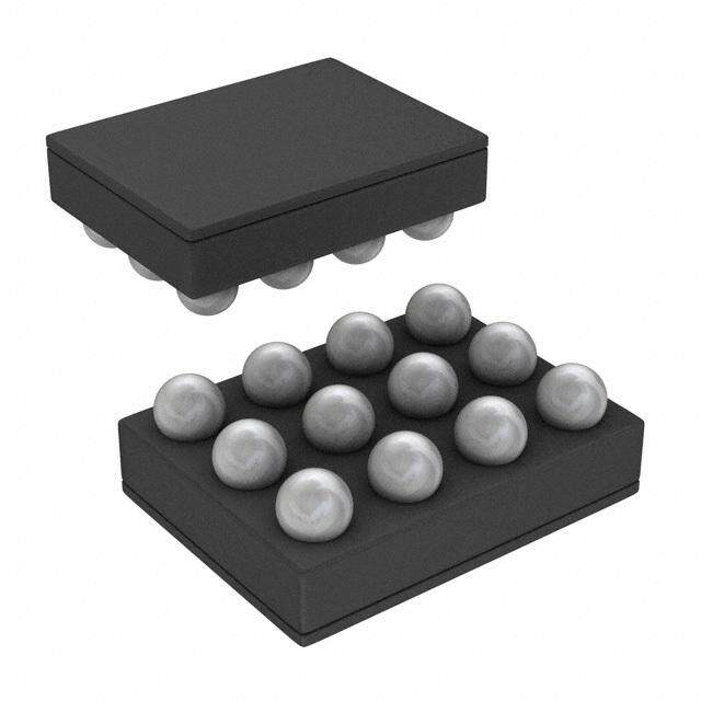
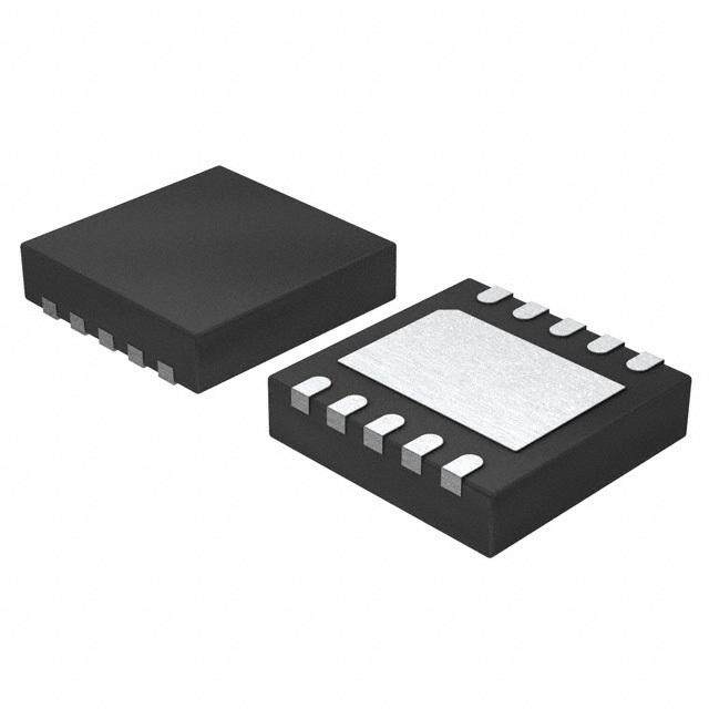
| 产品图片 |
|
| rohs | 符合RoHS无铅 / 符合限制有害物质指令(RoHS)规范要求 |
| 产品系列 | LED照明电子器件,LED照明驱动器,Texas Instruments TPS92550TZ/NOPB- |
| 数据手册 | |
| 产品型号 | TPS92550TZ/NOPB |
| 产品种类 | LED照明驱动器 |
| 供应商器件封装 | TO-PMOD-7 |
| 其它名称 | TPS92550TZ/NOPBDKR |
| 内部驱动器 | 是 |
| 包装 | Digi-Reel® |
| 商标 | Texas Instruments |
| 安装类型 | 表面贴装 |
| 安装风格 | SMD/SMT |
| 封装 | Reel |
| 封装/外壳 | TO-PMOD-7,电源模块 |
| 封装/箱体 | TO-PMOD-7 |
| 工作温度 | -40°C ~ 125°C |
| 工作频率 | 400 kHz |
| 工厂包装数量 | 250 |
| 恒压 | - |
| 恒流 | 是 |
| 拓扑 | PWM,降压(降压) |
| 拓扑结构 | Buck |
| 最大工作温度 | + 125 C |
| 最大电源电流 | 2.7 mA |
| 最小工作温度 | - 40 C |
| 标准包装 | 1 |
| 电压-电源 | 4.5 V ~ 36 V |
| 电压-输出 | - |
| 类型 | Inductive |
| 类型-初级 | 通用 |
| 类型-次级 | 白色 LED |
| 系列 | TPS92550 |
| 设计资源 | http://www.digikey.com/product-highlights/cn/zh/texas-instruments-webench-design-center/3176 |
| 输入电压 | 4.5 V to 36 V |
| 输出数 | 1 |
| 输出电流 | 450 mA |
| 输出端数量 | 1 Output |
| 输出类型 | Constant Current |
| 频率 | 365kHz ~ 450kHz |


- 商务部:美国ITC正式对集成电路等产品启动337调查
- 曝三星4nm工艺存在良率问题 高通将骁龙8 Gen1或转产台积电
- 太阳诱电将投资9.5亿元在常州建新厂生产MLCC 预计2023年完工
- 英特尔发布欧洲新工厂建设计划 深化IDM 2.0 战略
- 台积电先进制程称霸业界 有大客户加持明年业绩稳了
- 达到5530亿美元!SIA预计今年全球半导体销售额将创下新高
- 英特尔拟将自动驾驶子公司Mobileye上市 估值或超500亿美元
- 三星加码芯片和SET,合并消费电子和移动部门,撤换高东真等 CEO
- 三星电子宣布重大人事变动 还合并消费电子和移动部门
- 海关总署:前11个月进口集成电路产品价值2.52万亿元 增长14.8%


PDF Datasheet 数据手册内容提取
TPS92550 www.ti.com SNVS806C–MAY2012–REVISEDMAY2013 TPS92550 450mA 14W Constant Current Buck LED Driver Micro-Module CheckforSamples:TPS92550 FEATURES DESCRIPTION 1 • IntegratedallPowerComponentsIncluding The TPS92550 Constant Current Buck LED Driver 2 Micro-Module drives maximum 450mA LED current thePowerInductor up to 10 LEDs in a single string (maximum 14W). It • WideInputVoltageRange:4.5V–36V integrates all the power components including the • ConstantSwitchingFrequencyat400kHz power inductor. The TPS92550 provides a full turn- • HighContrastRatio(Minimumdimming key, highly efficient solution for wide range of single string LED lighting applications with up to 96% power currentpulsewidth< 16µs) efficiency. It accepts an input voltage ranging from • Drivesupto10LEDsinSeriesat36VInput 4.5V to 36V and delivers a 350mA LED current as • ±3.6%TypicalLEDCurrentAccuracy default. The LED current is adjustable from 300mA to 450mAbychangingasingleexternalresistor. • LEDCurrentAdjustablefrom300mAto450mA • Upto96%Efficiency The module operates at constant switching frequency (400kHz) with low Electro Magnetic Interference • TPS92550ModulescanbeConnectedin (EMI) complying with EN55015 standard. The module ParallelforHigherCurrentOperation has fast control loop to realize fine LED current pulse • InputUnder-VoltageLock-Out(UVLO) yielding 256–step PWM dimming resolution at 240Hz • CompatiblewithCeramicandLowESR for general lighting. Protection feature include thermal Capacitors shutdown, input under-voltage lockout, LED open- circuit and short-circuit protections. The TPS92550 • LowElectroMagneticInterference(EMI) Micro-Module is available in 7-pin PFM power ComplieswithEN55015Standard (1) package. • LEDOpenandShortCircuitProtections • ThermalShutdownandRoHSCompliant TPS92550 • –40°Cto+125˚CJunctionTemperatureRange APPLICATIONS EP • GeneralLighting,DeskLamps – CabinetLamps,DecorativeLamps – StreetLamps 1 2 3 4 5 6 7 • A–rcShpitoetctLuigrehtLsighting,RecessLights LED+ LED+ DIM GND VREF IADJ LED- – UnderwaterLights PACKAGE HIGHLIGHTS • 7LeadEasy-to-usePackage(SimilartoTO- CIN ILED 263) • SingleExposedDieAttachPadforEnhancing IIN High Power LED String ThermalPerformance VIN • 10.2x13.8x4.6mmPackage Figure1. TypicalApplicationCircuit (1) EN55015,refertoFigure36andFigure37 1 Pleasebeawarethatanimportantnoticeconcerningavailability,standardwarranty,anduseincriticalapplicationsof TexasInstrumentssemiconductorproductsanddisclaimerstheretoappearsattheendofthisdatasheet. Alltrademarksarethepropertyoftheirrespectiveowners. 2 PRODUCTIONDATAinformationiscurrentasofpublicationdate. Copyright©2012–2013,TexasInstrumentsIncorporated Products conform to specifications per the terms of the Texas Instruments standard warranty. Production processing does not necessarilyincludetestingofallparameters.
TPS92550 SNVS806C–MAY2012–REVISEDMAY2013 www.ti.com SYSTEM PERFORMANCE 100 10LED ILED(200mA/DIV) 8LED 95 6LED %) Y ( C EN 90 CI FI EF VDIM(2V/DIV) 85 80 20 24 28 32 36 VIN(V) 4 (cid:29)s/DIV Figure2.EfficiencyvsV ,I =350mA Figure3.LEDCurrentwithPWMDimming IN LED 16µsDimmingPulse Figure4.RadiatedEmissions(EN55015) EasytoUse7-PinPackage (1) θ measuredona1.705”x3.0”fourlayerboard,withoneouncecopper,thirtyfive12milthermalvias,noairflow, JA and1Wpowerdissipation. Figure5. 7-PinPFMPackage 10.16x13.77x4.57mm(0.4x0.39x0.18in) θ =20°C/W,θ =1.9°C/W(1) JA JC RoHSCompliant 2 SubmitDocumentationFeedback Copyright©2012–2013,TexasInstrumentsIncorporated ProductFolderLinks:TPS92550
TPS92550 www.ti.com SNVS806C–MAY2012–REVISEDMAY2013 CONNECTION DIAGRAM 7 LED- 6 IADJ 5 VREF Exposed Pad 4 GND Connect to GND 3 DIM 2 LED+ 1 LED+ Figure6. 7-PinPFM(TopView) SeeNDW0007APackage PINDESCRIPTIONS Pin Name Description Function Number 1,2 LED+ AnodeofLEDstring SupplyinputandrailconnectiontotheanodeoftheLEDstring. 3 DIM Dimmingsignalinput Dimmingcontrolsignalinput.OpentoenableorapplylogiclevelPWMsignal tocontrolthebrightnessoftheLEDstring. 4 GND Ground Referencepointforallstatedvoltages.Connecttotheexposedpadofthe packageexternally. 5 VREF Voltagereference Internalvoltagereferenceoutput. 6 IADJ LEDcurrentadjustment FinetunningoftheLEDcurrentbyconnectingaresistorbetweenthispinand ground.Connectthispintogroundforfactorypresetcurrent. 7 LED- CathodeofLEDstring ThecurrentreturnpinoftheLEDstring,connecttothecathodeoftheLED string. EP ExposedPad Exposedthermalpad Usedtodissipateheatfromthepackageduringoperation.Mustconnectto GNDdirectly. Copyright©2012–2013,TexasInstrumentsIncorporated SubmitDocumentationFeedback 3 ProductFolderLinks:TPS92550
TPS92550 SNVS806C–MAY2012–REVISEDMAY2013 www.ti.com Thesedeviceshavelimitedbuilt-inESDprotection.Theleadsshouldbeshortedtogetherorthedeviceplacedinconductivefoam duringstorageorhandlingtopreventelectrostaticdamagetotheMOSgates. ABSOLUTE MAXIMUM RATINGS (1) VALUE/UNITS LED+,LED-toGND -0.3Vto40V DIMtoGND -0.3Vto6V IADJ,VREFtoGND -0.3Vto5V ESDSusceptibility (2) ±2kV(AllpinsExceptPin6) PowerDissipation InternallyLimited JunctionTemperature 150°C StorageTemperatureRange 0°Cto150°C PeakReflowCaseTemperature(30sec) 245°C (1) AbsoluteMaximumRatingsarelimitsbeyondwhichdamagetothedevicemayoccur.OperatingRatingsareconditionsunderwhich operationofthedeviceisintendedtobefunctional.Forspecificationsandtestconditions,seetheElectricalCharacteristics. (2) Thehumanbodymodelisa100pFcapacitordischargedthrougha1.5kΩresistorintoeachpin.ThePin6(IADJpin)pass±1kV.Test methodisperJESD22-AI14S. RECOMMENDED OPERATING CONDITIONS (1) VALUE/UNITS LED+,LED- 4.5Vto36V DIM 0Vto5.5V IADJ 0Vto0.2V JunctionTemperature(T) –40°Cto125°C J (1) AbsoluteMaximumRatingsarelimitsbeyondwhichdamagetothedevicemayoccur.OperatingRatingsareconditionsunderwhich operationofthedeviceisintendedtobefunctional.Forspecificationsandtestconditions,seetheElectricalCharacteristics. 4 SubmitDocumentationFeedback Copyright©2012–2013,TexasInstrumentsIncorporated ProductFolderLinks:TPS92550
TPS92550 www.ti.com SNVS806C–MAY2012–REVISEDMAY2013 ELECTRICAL CHARACTERISTICS LimitsinstandardtypeareforT =25°Cunlessotherwisestated;limitsinboldfacetypeapplyovertheoperatingjunction J temperaturerangeT of–40°Cto125°C.Minimumandmaximumlimitsarespecifiedthroughtest,design,orstatistical J correlation.TypicalvaluesrepresentthemostlikelyparametricnormatT =25°C,andareprovidedforreferencepurposes J only.Unlessotherwisestatedthefollowingconditionsapply:V =24V,I =350mA.V isthevoltageappliedacrossLED+ IN LED IN andGND.I istheinputcurrentflowingintotheLED+node.I isaLEDcurrentflowingintotheLED-pin.V isthe IN LED LED voltageappliedacrossLED+andLED-.V isthevoltageappliedacrosstheDIMpintoground.ResistorR connectfrom DIM IADJ IADJpintoground.ResistorR connectfromVREFpintoground. VREF Symbol Parameter Conditions Min (1) Typ (2) Max (1) Units SYSTEMPARAMETERS I InputCurrent V =0V,4.5V≤V ≤36V,V =0V 2.0 2.35 2.7 mA IN LED IN DIM I LEDCurrent V =18V,R =0Ω,R =open,T =25°C 336 350 361 mA LED LED IADJ VREF J V =18V,R =0Ω,R =open, 328 350 361 LED IADJ VREF T =25°Cto125°C J V =18V,R =0Ω,R =open, 328 350 370 LED IADJ VREF T =–40°Cto125°C J I LEDCurrentatV =36V V =36V,V =24V,R =0Ω,R =open, 332 350 359 mA LED–36V IN IN LED IADJ VREF T =25°C J V =36V,V =24V,R =0Ω,R =open, 330 350 359 IN LED IADJ VREF T =25°Cto125°C J V =36V,V =24V,R =0Ω,R =open, 330 350 366 IN LED IADJ VREF T =–40°Cto125°C J I AdjustedLEDCurrent V =18V,R =0Ω,R =10.5kΩ,T =25°C 432 450 466 mA LED-ADJ1 LED IADJ VREF J V =18V,R =0Ω,R =10.5kΩ, 429 450 466 LED IADJ VREF T =25°Cto125°C J V =18,VR =0Ω,R =10.5kΩ, 429 450 474 LED IADJ VREF T =–40°Cto125°C J I AdjustedLEDCurrent V =18V,R =500Ω,R =open, 287 300 309 mA LED-ADJ2 LED IADJ VREF T =25°C J V =18V,R =500Ω,R =open, 283 300 309 LED IADJ VREF T =25°Cto125°C J V =18V,R =500Ω,R =open, 283 300 315 LED IADJ VREF T =–40°Cto125°C J I LEDShortCircuitCurrent V =0V,V =36V,DIM=open 800 900 1020 mA LED-SHORT LED IN atV =36V IN I “LED-”pinleakage V =0V,V =operatingmax,DIM=0V 1.2 µA LED-LEAK LED IN current f SwitchingFrequency V =12V,R =0Ω,R =open 365 400 450 kHz SW LED IADJ VREF V DIMPinThreshold V Increasing 1.0 1.2 V DIM DIM V DIMPinHysteresis 0.25 V DIM-HYS THERMALCHARACTERISTICS T ThermalShutdown T Rising 170 °C SD J Temperature T ThermalShutdownTemp. T Rising 10 °C SD-HYS J Hysteresis θ JunctiontoAmbient(3) 4LayerJEDECPrintedCircuitBoard,100vias,Noairflow 19.3 °C/W JA 2LayerJEDECPCB,Noairflow 21.5 θ JunctiontoCase Noairflow 1.9 °C/W JC (1) MinandMaxlimitsare100%productiontestedatanambienttemperature(T )of25°C.Limitsovertheoperatingtemperaturerangeare A specifiedthroughcorrelationusingStatisticalQualityControl(SQC)methods.LimitsareusedtocalculateAverageOutgoingQuality Level(AOQL). (2) Typicalnumbersareat25°Candrepresentthemostlikelyparametricnorm. (3) θ measuredona1.705”x3.0”fourlayerboard,withoneouncecopper,thirtyfive12milthermalvias,noairflow,and1Wpower JA dissipation. Copyright©2012–2013,TexasInstrumentsIncorporated SubmitDocumentationFeedback 5 ProductFolderLinks:TPS92550
TPS92550 SNVS806C–MAY2012–REVISEDMAY2013 www.ti.com TYPICAL PERFORMANCE CHARACTERISTICS Unlessotherwisespecified,thefollowingconditionsapply:V =24V,C isa2.2µF100VX7Rceramiccapacitorfordriving IN IN 2–7powerLEDswithI =350mA.SingleLEDforwardvoltageusedis3.2V.T =25°Cforefficiencycurvesandwaveforms. LED A Efficiencyvs I Regulationvs LED V ,I =350mA V ,I =350mA IN LED IN LED 100 3 95 3LED 2 90 4LED %) 3LED %) N ( 1 2LED CY ( 85 TIO 4LED CIEN 80 2LED GULA 0 FFI 75 RE -1 1LED E D 70 1LED E L I -2 65 60 -3 0 4 8 12 16 20 24 28 32 36 0 4 8 12 16 20 24 28 32 36 VIN(V) VIN(V) Figure7. Figure8. Efficiencyvs I Regulationvs LED V ,I =350mA V ,I =350mA IN LED IN LED 100 3 10LED 8LED 2 6LED 95 6LED %) %) N ( 1 8LED CY ( TIO 10LED CIEN 90 GULA 0 FI E F R -1 E D 85 E L I -2 80 -3 20 24 28 32 36 20 24 28 32 36 VIN(V) VIN(V) Figure9. Figure10. Efficiencyvs I Regulationvs LED V ,I =450mA V ,I =450mA IN LED IN LED 100 3 95 3LED 4LED 2 90 %) %) N ( 1 3LED 4LED CY ( 85 TIO 2LED CIEN 80 2LED GULA 0 FI 75 E EF RD -1 1LED 70 E 1LED IL -2 65 60 -3 0 4 8 12 16 20 24 28 32 36 0 4 8 12 16 20 24 28 32 36 VIN(V) VIN(V) Figure11. Figure12. 6 SubmitDocumentationFeedback Copyright©2012–2013,TexasInstrumentsIncorporated ProductFolderLinks:TPS92550
TPS92550 www.ti.com SNVS806C–MAY2012–REVISEDMAY2013 TYPICAL PERFORMANCE CHARACTERISTICS (continued) Unlessotherwisespecified,thefollowingconditionsapply:V =24V,C isa2.2µF100VX7Rceramiccapacitorfordriving IN IN 2–7powerLEDswithI =350mA.SingleLEDforwardvoltageusedis3.2V.T =25°Cforefficiencycurvesandwaveforms. LED A Efficiencyvs I Regulationvs LED V ,I =450mA V ,I =450mA IN LED IN LED 100 3 8LED 10LED 2 95 6LED %) 6LED %) N ( 1 8LED CY ( TIO 10LED CIEN 90 GULA 0 FI E F R -1 E D 85 E L I -2 80 -3 20 24 28 32 36 20 24 28 32 36 VIN(V) VIN(V) Figure13. Figure14. Efficiencyvs I Regulationvs LED V ,I =300mA V ,I =300mA IN LED IN LED 100 3 95 3LED 2 3LED 90 4LED %) 2LED %) N ( 1 CY ( 85 TIO 4LED CIEN 80 2LED GULA 0 FFI 75 RE -1 1LED E 1LED D 70 E L I -2 65 60 -3 0 4 8 12 16 20 24 28 32 36 0 4 8 12 16 20 24 28 32 36 VIN(V) VIN(V) Figure15. Figure16. Efficiencyvs I Regulationvs LED V ,I =300mA V ,I =300mA IN LED IN LED 100 3 6LED 8LED 10LED 2 6LED 95 %) 8LED %) N ( 1 CY ( TIO 10LED CIEN 90 GULA 0 FI E F R -1 E D 85 E L I -2 80 -3 20 24 28 32 36 20 24 28 32 36 VIN(V) VIN(V) Figure17. Figure18. Copyright©2012–2013,TexasInstrumentsIncorporated SubmitDocumentationFeedback 7 ProductFolderLinks:TPS92550
TPS92550 SNVS806C–MAY2012–REVISEDMAY2013 www.ti.com TYPICAL PERFORMANCE CHARACTERISTICS (continued) Unlessotherwisespecified,thefollowingconditionsapply:V =24V,C isa2.2µF100VX7Rceramiccapacitorfordriving IN IN 2–7powerLEDswithI =350mA.SingleLEDforwardvoltageusedis3.2V.T =25°Cforefficiencycurvesandwaveforms. LED A LEDCurrentwithPWMDimming LEDCurrentwithPWMDimming V Rising V Falling DIM DIM ILED(200mA/DIV) ILED(200mA/DIV) VDIM(2V/DIV) VDIM(2V/DIV) 2 (cid:29)s/DIV 2 (cid:29)s/DIV Figure19. Figure20. LEDCurrentwithPWMDimming I vsV IN IN 16µsdimmingpulse V =0V DIM 3.0 ILED(200mA/DIV) TJ=25°C 2.5 2.0 A) TJ=-40°C m (N 1.5 II TJ=125°C VDIM(2V/DIV) 1.0 0.5 0.0 0 4 8 12 16 20 24 28 32 36 4 (cid:29)s/DIV VIN(V) Figure21. Figure22. I vsV I vsV IN IN LED IN LED=open,DIM=open 3LED 3.5 450 TJ=25°C 400 3.0 TJ=-40°C 350 2.5 300 I(mA)IN 12..50 TJ=-40°C TJ=125°C I(mA)LED 220500 TJ=25°C TJ=125°C 150 1.0 100 0.5 50 0.0 0 0 4 8 12 16 20 24 28 32 36 0 4 8 12 16 20 24 28 32 36 VIN(V) VIN(V) Figure23. Figure24. 8 SubmitDocumentationFeedback Copyright©2012–2013,TexasInstrumentsIncorporated ProductFolderLinks:TPS92550
TPS92550 www.ti.com SNVS806C–MAY2012–REVISEDMAY2013 TYPICAL PERFORMANCE CHARACTERISTICS (continued) Unlessotherwisespecified,thefollowingconditionsapply:V =24V,C isa2.2µF100VX7Rceramiccapacitorfordriving IN IN 2–7powerLEDswithI =350mA.SingleLEDforwardvoltageusedis3.2V.T =25°Cforefficiencycurvesandwaveforms. LED A I vsV I vsV LED IN IN IN V =0V,DIM=open V =0V,DIM=open LED LED 1000 100 TJ=125°C 800 80 TJ=125°C (mA)ED 600 TJ=-40°C (mA)N 60 TJ=-40°C L 400 II 40 I 200 20 TJ=25°C TJ=25°C 0 0 0 4 8 12 16 20 24 28 32 36 0 4 8 12 16 20 24 28 32 36 VIN(V) VIN(V) Figure25. Figure26. I vsDimmingDutyRatio I vsDimmingDutyRatio LED LED 100 1.0 90 VIN=12V(2LED) 80 0.8 70 VIN=24V(4LED) %) 60 %) 0.6 VIN=24V(4LED) (D 50 (D E E L L I 40 I 0.4 VIN=36V(6LED) 30 20 VIN=36V(6LED) 0.2 10 VIN=12V(2LED) 0 0.0 0 10 20 30 40 50 60 70 80 90100 0.0 0.2 0.4 0.6 0.8 1.0 DIM DUTY RATIO (%) DIM DUTY RATIO (%) Figure27. Figure28. FrequencyDeviationvsV (400kHz) I RegulationvsTemperature IN LED 3 3 N (%) 2 TJ=-40°C %) 2 VIN=12V(2LED) TIO 1 N ( 1 A TJ=25°C O VI TI E A D 0 L 0 Y GU QUENC -1 TJ=125°C RELED -1 VIN=36V(6LED) RE -2 I -2 F VIN=24V(4LED) -3 -3 8 12 16 20 24 28 32 36 -50 -25 0 25 50 75 100 125 VIN(V) TEMPERATURE (°C) Figure29. Figure30. Copyright©2012–2013,TexasInstrumentsIncorporated SubmitDocumentationFeedback 9 ProductFolderLinks:TPS92550
TPS92550 SNVS806C–MAY2012–REVISEDMAY2013 www.ti.com TYPICAL PERFORMANCE CHARACTERISTICS (continued) Unlessotherwisespecified,thefollowingconditionsapply:V =24V,C isa2.2µF100VX7Rceramiccapacitorfordriving IN IN 2–7powerLEDswithI =350mA.SingleLEDforwardvoltageusedis3.2V.T =25°Cforefficiencycurvesandwaveforms. LED A I vsR I vsR LED IADJ LED VREF R =open R =0Ω VREF IADJ 350 450 340 425 A) 330 A) m m (D (D 400 E E L 320 L I I 375 310 300 350 0 100 200 300 400 500 0 20 40 60 80 100 RIADJ((cid:13)) RVREF(k(cid:13)) Figure31. Figure32. 10 SubmitDocumentationFeedback Copyright©2012–2013,TexasInstrumentsIncorporated ProductFolderLinks:TPS92550
TPS92550 www.ti.com SNVS806C–MAY2012–REVISEDMAY2013 BLOCK DIAGRAM 1,2 LED+ VIN 4.5V to 36V VCC 0.33 PF y CIN a RVeoglutalagteor 1 PF ED Arr L er w 7 o 47 PH LED- h p g Hi 4 EP Switch Control logic 4 GND 6 IADJ 3 k(cid:13) 5 VREF VCC 3 + DIM - 1.2V Operation Description The TPS92550 is a high power floating buck LED driver with wide input voltage range. It requires no external current sensing elements and loop compensation network. The integrated power switch enables high output powerupto14Wwith450mALEDcurrent. High speed dimming control input allows precision and high resolution brightness control for applications which requirefinebrightnessadjustment. Copyright©2012–2013,TexasInstrumentsIncorporated SubmitDocumentationFeedback 11 ProductFolderLinks:TPS92550
TPS92550 SNVS806C–MAY2012–REVISEDMAY2013 www.ti.com APPLICATION INFORMATION SETTINGTHELEDCURRENT TheTPS92550requiresnoexternalcurrentsensingresistorforLEDcurrentregulation.TheaverageLEDcurrent of the TPS92550 is adjustable from 300mA to 450mA by varying the resistance of the resistor according to the followingequationandtable. ForR =openandR <=499Ω VREF IADJ 1050 I LED 3k(cid:14)RIADJ (1) ForR =0andR >=10.5kΩ IADJ VREF 1050 I LED 3k//RVREF (2) Table1.ExampleforI Setting LED R (Ω) R (Ω) I (mA) IADJ VREF LED 499 OPEN 300 SHORT OPEN 350 SHORT 10.5k 450 TPS92550 EP 1234567 LED+ LED+DIMGNDVREF IADJLED- R R VREF IADJ C IN ILED IIN High Power LED String VIN Figure33. TPS92550ApplicationSchematicforI Setting LED Minimum Switch On-Time The on-time of the internal switch should be no shorter than 400ns. The number of LED (typical forward voltage at3.2V)toinputvoltageisconstrainedbythatasshowninthefollowingtable. No.ofLED Max.V (V) IN 1 20 2–10 36 Peak Switch Current Limit The TPS92550 features an integrated switch current limiting mechanism to prevent the LEDs from being over- driven. The switch current limiter is triggered when the switch current is three times exceeding the current level setbyresistor.Oncethecurrentlimiteristriggered,theinternalpowerswitchturnOFFfor3.6µstodischargethe inductor until inductor current reduces back to normal level. The current limiting feature is exceptionally important toavoidpermanentdamageoftheTPS92550applicationcircuitduetoshortcircuitofLEDstring. 12 SubmitDocumentationFeedback Copyright©2012–2013,TexasInstrumentsIncorporated ProductFolderLinks:TPS92550
TPS92550 www.ti.com SNVS806C–MAY2012–REVISEDMAY2013 PWM Dimming Control The DIM pin of the TPS92550 is an input with internal pull-up that accepts logic signals for average LED current control. Applying a logic high (above 1.2V) signal to the DIM pin or leaving the DIM pin open will enable the device. Applying a logic low signal (below 0.7V) to the DIM pin will disable the switching activity of the device but maintain operation of the VCC regulator active. The TPS92550 operation of high speed dimming and very fine dimmingcontrolasshowninFigure34. Figure34. ShortenedCurrentSlewupTimeoftheTPS92550 To ensure normal operation of the TPS92550, it is recommended to set the dimming frequency not higher than 1/10 of the switching frequency. The dim pulse on time is tested down to 16µs. In applications that require high dimmingcontrastratio,lowdimmingfrequencyshouldbeused. Parallel Operation When a load current higher than 450mA is required by the application, TPS92550 can be used in parallel to deliver higher current. With common VINs and GNDs, the TPS92550 will operate as independent asynchronous current sinks driving the same LED load. The total DC current of the modules will be additive; however, low frequency sub-harmonic current ripple may be present and its frequency and magnitude will depend upon the phase relationship between the internal clocks as there is no provision for synchronizing driver clocks. It is suggested to have minimum 2.2μF C located close to the module to filter out the current ripple, and the OUT resultant LED current will become DC. Current sharing modules should have a local C capacitor of minimum IN 2.2μF located as close to V and GND as possible. Refer to Figure 35 for the TPS92550 parallel operation IN circuitschematic.RefertoFigure36fortheTPS92550paralleloperationresultsI vsV . LED IN VIN TPS92550 TPS92550 ILED EP EP ng Stri D E T T L OU OU er 12 3 4 5 6 7 C 12 3 4 5 6 7 C ow P LED+LED+DIM GND VREF IADJLED- LED+ LED+DIM GND VREF IADJLED- High ILED1 ILED2 C IN C IN Figure35. ParallelOperationCircuitSchematicforI =900mA LED Copyright©2012–2013,TexasInstrumentsIncorporated SubmitDocumentationFeedback 13 ProductFolderLinks:TPS92550
TPS92550 SNVS806C–MAY2012–REVISEDMAY2013 www.ti.com 1.0 0.9 0.8 1LED 5LED 0.7 A) 0.6 (D 0.5 E L I 0.4 10LED 0.3 0.2 0.1 0.0 0 10 20 30 40 VIN(V) Figure36. ParallelOperationResultsforI =900mA,I vsV LED LED IN PC Board Layout Considerations The overall performance of the LED driver is highly depends on the PCB layout. Poor board layout can disrupt the performance of the TPS92550 and surrounding circuitry by contributing to EMI, ground bounce and resistive voltage drop in the traces. These can send erroneous signals to the LED driver resulting in poor regulation and stability.Goodlayoutcanbeimplementedbyfollowingafewsimpledesignrules. 1. PlaceC ascloseaspossibletotheV pinandGNDexposedpad(EP). IN IN 2. Place C (optional for reduction of LED current ripple and EMI compliance) as close as possible to the OUT VLED+pinandVLED-pin. 3. Theexposedpad(EP)mustconnecttotheGNDpindirectly. EMI Design Considerations From an EMI reduction standpoint, it is imperative to minimize the di/dt current paths (refer to Figure 37). Therefore, it is essential to connect an 2.2µF capacitor (C ) across the LED+ pin and LED- pin. This will OUT minimizetheripplecurrentsothatitcanreduceradiatedEMI(refertoFigure38andFigure39). High power LED Array COUT di/dt Loop 2 VIN LED+ LED- TPS92550 CIN GND Loop1 Figure37. CurrentLoops 14 SubmitDocumentationFeedback Copyright©2012–2013,TexasInstrumentsIncorporated ProductFolderLinks:TPS92550
TPS92550 www.ti.com SNVS806C–MAY2012–REVISEDMAY2013 Figure38.ComplieswithEN55015Radiated Figure39.ComplieswithEN55015Radiated Emissions(HORI./HEIGHT=3.0m/RANGE=10m) Emissions(VERT./HEIGHT=1.0m/RANGE=10m) C =2.2µF,C =2.2uF,V =36V,I =350mA, C =2.2µF,C =2.2uF,V =36V,I =350mA, IN OUT IN LED IN OUT IN LED No.ofLED=10 No.ofLED=10 TPS92550 Application Circuit Schematic and BOM High power LED Array U1 VIN 1,2 7 LED+ LED- PWM Dimming TPS92550 CIN 3 Signal 2.2 PF DIM 100V IADJ GND VREF 6 4,EP 5 Table2.BillofMaterials,V =18V,I =350mA,No.ofLED=2—5 IN LED Designator Description CaseSize Manufacturer ManufacturerP/N Quantity U1 LEDMicro-ModuleDriver PFM TexasInstruments TPS92550TZ 1 C 2.2µF,100V,X7R 1210 Murata GRM32ER72A225KA35L 1 IN High power LED Array COUT 2.2 PF 100V U1 VIN 1,2 7 LED+ LED- PWM Dimming CIN TPS92550 Signal 2.2 PF DIM 3 100V IADJ GND VREF 6 4,EP 5 Table3. BillofMaterials,V =36V,I =350mA,No.ofLED=10,ComplieswithEN55015Radiated IN LED Copyright©2012–2013,TexasInstrumentsIncorporated SubmitDocumentationFeedback 15 ProductFolderLinks:TPS92550
TPS92550 SNVS806C–MAY2012–REVISEDMAY2013 www.ti.com Table3. BillofMaterials,V =36V,I =350mA,No.ofLED=10,ComplieswithEN55015Radiated IN LED Emissions(continued) Emissions Designator Description CaseSize Manufacturer ManufacturerP/N Quantity U1 LEDMicro-ModuleDriver PFM TexasInstruments TPS92550TZ 1 C 2.2µF,100V,X7R 1210 Murata GRM32ER72A225KA35L 1 IN C 2.2µF,100V,X7R 1210 Murata GRM32ER72A225KA35L 1 OUT PCB Layout Diagrams ThePCBdesignisavailableintheTPS92550productfolderatwww.ti.com. Figure40. TopLayerandTopOverlay 16 SubmitDocumentationFeedback Copyright©2012–2013,TexasInstrumentsIncorporated ProductFolderLinks:TPS92550
TPS92550 www.ti.com SNVS806C–MAY2012–REVISEDMAY2013 Figure41. BottomLayerandBottomOverlay Copyright©2012–2013,TexasInstrumentsIncorporated SubmitDocumentationFeedback 17 ProductFolderLinks:TPS92550
TPS92550 SNVS806C–MAY2012–REVISEDMAY2013 www.ti.com Figure42. TopOverlay 18 SubmitDocumentationFeedback Copyright©2012–2013,TexasInstrumentsIncorporated ProductFolderLinks:TPS92550
TPS92550 www.ti.com SNVS806C–MAY2012–REVISEDMAY2013 REVISION HISTORY ChangesfromRevisionB(May2013)toRevisionC Page • ChangedlayoutofNationalDataSheettoTIformat.......................................................................................................... 18 Copyright©2012–2013,TexasInstrumentsIncorporated SubmitDocumentationFeedback 19 ProductFolderLinks:TPS92550
PACKAGE OPTION ADDENDUM www.ti.com 14-Mar-2020 PACKAGING INFORMATION Orderable Device Status Package Type Package Pins Package Eco Plan Lead/Ball Finish MSL Peak Temp Op Temp (°C) Device Marking Samples (1) Drawing Qty (2) (6) (3) (4/5) TPS92550TZ/NOPB ACTIVE TO-PMOD NDW 7 250 RoHS (In SN Level-3-245C-168 HR -40 to 125 TPS92550 Work) & Green TZ (In Work) TPS92550TZX/NOPB ACTIVE TO-PMOD NDW 7 500 RoHS (In SN Level-3-245C-168 HR -40 to 125 TPS92550 Work) & Green TZ (In Work) (1) The marketing status values are defined as follows: ACTIVE: Product device recommended for new designs. LIFEBUY: TI has announced that the device will be discontinued, and a lifetime-buy period is in effect. NRND: Not recommended for new designs. Device is in production to support existing customers, but TI does not recommend using this part in a new design. PREVIEW: Device has been announced but is not in production. Samples may or may not be available. OBSOLETE: TI has discontinued the production of the device. (2) RoHS: TI defines "RoHS" to mean semiconductor products that are compliant with the current EU RoHS requirements for all 10 RoHS substances, including the requirement that RoHS substance do not exceed 0.1% by weight in homogeneous materials. Where designed to be soldered at high temperatures, "RoHS" products are suitable for use in specified lead-free processes. TI may reference these types of products as "Pb-Free". RoHS Exempt: TI defines "RoHS Exempt" to mean products that contain lead but are compliant with EU RoHS pursuant to a specific EU RoHS exemption. Green: TI defines "Green" to mean the content of Chlorine (Cl) and Bromine (Br) based flame retardants meet JS709B low halogen requirements of <=1000ppm threshold. Antimony trioxide based flame retardants must also meet the <=1000ppm threshold requirement. (3) MSL, Peak Temp. - The Moisture Sensitivity Level rating according to the JEDEC industry standard classifications, and peak solder temperature. (4) There may be additional marking, which relates to the logo, the lot trace code information, or the environmental category on the device. (5) Multiple Device Markings will be inside parentheses. Only one Device Marking contained in parentheses and separated by a "~" will appear on a device. If a line is indented then it is a continuation of the previous line and the two combined represent the entire Device Marking for that device. (6) Lead/Ball Finish - Orderable Devices may have multiple material finish options. Finish options are separated by a vertical ruled line. Lead/Ball Finish values may wrap to two lines if the finish value exceeds the maximum column width. Important Information and Disclaimer:The information provided on this page represents TI's knowledge and belief as of the date that it is provided. TI bases its knowledge and belief on information provided by third parties, and makes no representation or warranty as to the accuracy of such information. Efforts are underway to better integrate information from third parties. TI has taken and continues to take reasonable steps to provide representative and accurate information but may not have conducted destructive testing or chemical analysis on incoming materials and chemicals. TI and TI suppliers consider certain information to be proprietary, and thus CAS numbers and other limited information may not be available for release. Addendum-Page 1
PACKAGE OPTION ADDENDUM www.ti.com 14-Mar-2020 In no event shall TI's liability arising out of such information exceed the total purchase price of the TI part(s) at issue in this document sold by TI to Customer on an annual basis. Addendum-Page 2
PACKAGE MATERIALS INFORMATION www.ti.com 15-Apr-2016 TAPE AND REEL INFORMATION *Alldimensionsarenominal Device Package Package Pins SPQ Reel Reel A0 B0 K0 P1 W Pin1 Type Drawing Diameter Width (mm) (mm) (mm) (mm) (mm) Quadrant (mm) W1(mm) TPS92550TZ/NOPB TO- NDW 7 250 330.0 24.4 10.6 14.22 5.0 16.0 24.0 Q2 PMOD TPS92550TZX/NOPB TO- NDW 7 500 330.0 24.4 10.6 14.22 5.0 16.0 24.0 Q2 PMOD PackMaterials-Page1
PACKAGE MATERIALS INFORMATION www.ti.com 15-Apr-2016 *Alldimensionsarenominal Device PackageType PackageDrawing Pins SPQ Length(mm) Width(mm) Height(mm) TPS92550TZ/NOPB TO-PMOD NDW 7 250 367.0 367.0 45.0 TPS92550TZX/NOPB TO-PMOD NDW 7 500 367.0 367.0 45.0 PackMaterials-Page2
MECHANICAL DATA NDW0007A BOTTOM SIDE OF PACKAGE TOP SIDE OF PACKAGE TZA07A (Rev D) www.ti.com
IMPORTANTNOTICEANDDISCLAIMER TI PROVIDES TECHNICAL AND RELIABILITY DATA (INCLUDING DATASHEETS), DESIGN RESOURCES (INCLUDING REFERENCE DESIGNS), APPLICATION OR OTHER DESIGN ADVICE, WEB TOOLS, SAFETY INFORMATION, AND OTHER RESOURCES “AS IS” AND WITH ALL FAULTS, AND DISCLAIMS ALL WARRANTIES, EXPRESS AND IMPLIED, INCLUDING WITHOUT LIMITATION ANY IMPLIED WARRANTIES OF MERCHANTABILITY, FITNESS FOR A PARTICULAR PURPOSE OR NON-INFRINGEMENT OF THIRD PARTY INTELLECTUAL PROPERTY RIGHTS. These resources are intended for skilled developers designing with TI products. You are solely responsible for (1) selecting the appropriate TI products for your application, (2) designing, validating and testing your application, and (3) ensuring your application meets applicable standards, and any other safety, security, or other requirements. These resources are subject to change without notice. TI grants you permission to use these resources only for development of an application that uses the TI products described in the resource. Other reproduction and display of these resources is prohibited. No license is granted to any other TI intellectual property right or to any third party intellectual property right. TI disclaims responsibility for, and you will fully indemnify TI and its representatives against, any claims, damages, costs, losses, and liabilities arising out of your use of these resources. TI’s products are provided subject to TI’s Terms of Sale (www.ti.com/legal/termsofsale.html) or other applicable terms available either on ti.com or provided in conjunction with such TI products. TI’s provision of these resources does not expand or otherwise alter TI’s applicable warranties or warranty disclaimers for TI products. Mailing Address: Texas Instruments, Post Office Box 655303, Dallas, Texas 75265 Copyright © 2020, Texas Instruments Incorporated