ICGOO在线商城 > STR-Y6753

 Datasheet下载
- 型号: STR-Y6753
- 制造商: Sanken
- 库位|库存: xxxx|xxxx
- 要求:
| 数量阶梯 | 香港交货 | 国内含税 |
| +xxxx | $xxxx | ¥xxxx |
查看当月历史价格
查看今年历史价格
STR-Y6753产品简介:
ICGOO电子元器件商城为您提供STR-Y6753由Sanken设计生产,在icgoo商城现货销售,并且可以通过原厂、代理商等渠道进行代购。 提供STR-Y6753价格参考以及SankenSTR-Y6753封装/规格参数等产品信息。 你可以下载STR-Y6753参考资料、Datasheet数据手册功能说明书, 资料中有STR-Y6753详细功能的应用电路图电压和使用方法及教程。
| 参数 | 数值 |
| 产品目录 | 集成电路 (IC) |
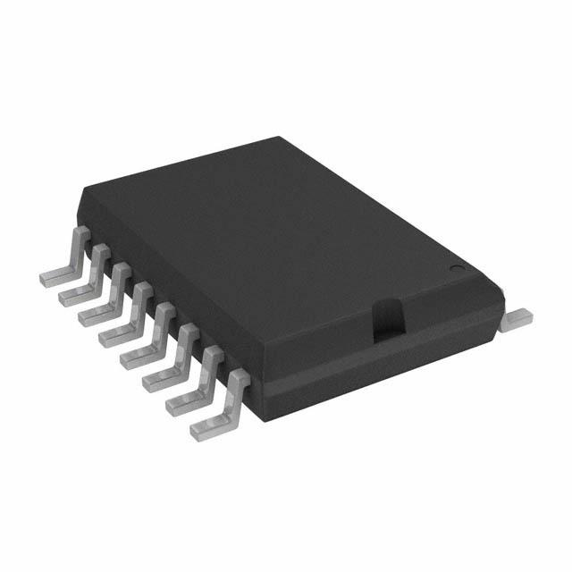
| 描述 | IC REG PWM CONV AC/DC TO-220F-7 |
| 产品分类 | |
| 品牌 | Sanken |
| 数据手册 | |
| 产品图片 | |
| 产品型号 | STR-Y6753 |
| rohs | 无铅 / 符合限制有害物质指令(RoHS)规范要求 |
| 产品系列 | - |
| 供应商器件封装 | TO-220-7 |
| 功率(W) | 60W |
| 包装 | 散装 |
| 封装/外壳 | TO-220-7 成形引线 |
| 工作温度 | -20°C ~ 115°C |
| 标准包装 | 50 |
| 电压-击穿 | 650V |
| 电压-输入 | 9.4 V ~ 35 V |
| 电压-输出 | - |
| 输出隔离 | 隔离 |
| 频率范围 | 18.4kHz ~ 24.4kHz |


PDF Datasheet 数据手册内容提取
Quasi-Resonant Controllers with Integrated Power MOSFET STR-Y6700 Series General Descriptions Package The STR-Y6700 series are power ICs for switching TO220F-7L power supplies, incorporating a MOSFET and a quasi-resonant controller IC. Including an auto standby function in the controller, the product achieves the low standby power by the automatic switching between the quasi-resonant operation in normal operation, one bottom-skip operation under medium to light load conditions and the s burst-oscillation under light load conditions. Notn to Scale The product achieves high cost-performance power supply systems with few external components. g i Features Lineup s e • Multi-mode Control • Electrical Characteristics D The optimum operation depending on load conditions Products VDSS(min.) RDS(ON)(max.) is changed automatically and is achieved high STR–Y6735 efficiency operation across the full range of loads. STR–Y6735A w 500 V 0.8 Ω STR–Y6753 e 1.9 Ω Operation Mode N 650 V STR–Y6754 1.4 Ω Normal load ------------------------- Quasi-resonant mode Medium to light load ------------- One bottom-skip mode SSTTRR––rYY 66776666 A 1.7 Ω Light load -------------------------- Burst oscillation mode o STR–Y6765 800 V 2.2 Ω (Auto standby function) f • No load power consumption STR–Y6763 3.5 Ω d STR–Y6763A P < 30 mW (100VAC) IN P < 50 mW (230VAC) e IN • Leading Edge Blanking Function d • Output Power, POUT(2) • Bias Assist Function n Products POUT (Open frame) • Built-in startup circuit reduces e 380VDC 85~265VAC • Protections m STR–Y6735 120 W(100VAC) – STR–Y6735A Overcurrent Protection 1 (OCP1): Pulse-by-Pulse, with m STR–Y6753 100 W 60 W Input Compensation Function Overcurrent Protection 2 (OCP2)(1): Latched shutdown STR–Y6754 120 W 67 W o Overload Protection (OLP): Latched shutdown STR–Y6766 c 140 W 80 W Overvoltage Protection (OVP): Latched shutdown STR–Y6766A e Thermal Shutdown Protection (TSD): Latched shutdown STR–Y6765 120 W 70 W R STR–Y6763 (1) Products with the last letter "A" don’t have the 80 W 50 W STR–Y6763A OCP2 function. t o (2) The output power is actual continues power that is measured at N 50 °C ambient. The peak output power can be 120 to 140 % of Typical Application the value stated here. Core size, ON Duty, and thermal design affect the output power. It may be less than the value stated here. BR1 T1 D51 L51 VOUT(+) VAC C1 P R54 PC1 R51 Applications C51 R55 S R52 C53 • White goods U1 C52 R53 • Office automation equipment STR-Y6700 D2 R2 U51 R56 • Industrial equipment D/ST1 2S/OCP2VCC3GND4FB/OLP5BD6NF7 C3 DZBDD VOUT(-) RBD1 ROCP RC34 C5 PC1 CBD RBD2 CY STR-Y6700 - DS Rev.4.2 SANKEN ELECTRIC CO., LTD. 1 Mar. 17, 2020 https://www.sanken-ele.co.jp/en/
STR-Y6700 Series CONTENTS General Descriptions ------------------------------------------------------------------------------------------ 1 1. Absolute Maximum Ratings ----------------------------------------------------------------------------- 3 2. Electrical Characteristics -------------------------------------------------------------------------------- 4 3. Performance Curves -------------------------------------------------------------------------------------- 6 3.1 Derating Curves ------------------------------------------------------------------------------------ 6 3.2 Ambient Temperature versus Power Dissipation Curves ---------------------------------- 6 3.3 MOSFET Safe Operating Area Curves ------------------------------------------------------- 8 3.4 Transient Thermal Resistance Curves --------------------------------------------------------- 9 s 4. Block Diagram ------------------------------------------------------------------------------------------- 10 n 5. Pin Configuration Definitions ------------------------------------------------------------------g------- 10 6. Typical Application ---------------------------------------------------------------------------i---------- 11 s e 7. Physical Dimensions ------------------------------------------------------------------------------------ 12 D 8. Marking Diagram --------------------------------------------------------------------------------------- 12 9. Operational Description -----------------------------------------------------w-------------------------- 13 9.1 Startup Operation ------------------------------------------------------------------------------- 13 e 9.2 Undervoltage Lockout (UVLO) --------------------------------------------------------------- 13 N 9.3 Bias Assist Function ----------------------------------------------------------------------------- 13 9.4 Soft Start Function -------------------------------------- ---------------------------------------- 14 r 9.5 Constant Output Voltage Control ------------------------------------------------------------ 15 o 9.6 Leading Edge Blanking Function ------------------------------------------------------------- 15 f 9.7 Quasi-Resonant Operation and Bottom-On Timing Setup ------------------------------ 15 9.7.1 Quasi-Resonant Operation ------d------------------------------------------------------ 15 9.7.2 Bottom-On Timing Setup ---e---------------------------------------------------------- 16 9.8 BD Pin Blanking Time -------------d------------------------------------------------------------- 17 9.9 Multi-mode Control ----------------------------------------------------------------------------- 18 n 9.9.1 One Bottom-Skip Quasi-Resonant Operation ------------------------------------- 18 e 9.9.2 Automatic Standby Mode Function ------------------------------------------------- 19 m 9.10 Maximum On-Time Limitation Function --------------------------------------------------- 19 9.11 Overcurrent Protection (OCP) ---------------------------------------------------------------- 20 m 9.11.1 Overcurrent Protection 1 (OCP1) --------------------------------------------------- 20 9.11.2 Overcuorrent Protection 2 (OCP2) --------------------------------------------------- 20 9.11.3 OCP1 Input Compensation Function ----------------------------------------------- 20 c 9.11.4 When Overcurrent Input Compensation is Not Required ---------------------- 23 e 9.12 Overload Protection (OLP) -------------------------------------------------------------------- 23 R 9.13 Overvoltage Protection (OVP) ---------------------------------------------------------------- 24 9.14 T hermal Shutdown (TSD) ---------------------------------------------------------------------- 24 t o 10. Design Notes ---------------------------------------------------------------------------------------------- 25 N10.1 External Components --------------------------------------------------------------------------- 25 10.2 Transformer Design ----------------------------------------------------------------------------- 27 10.3 PCB Trace Layout and Component Placement -------------------------------------------- 28 11. Pattern Layout Example ------------------------------------------------------------------------------- 30 12. Reference Design of Power Supply ------------------------------------------------------------------ 31 Important Notes ---------------------------------------------------------------------------------------------- 33 STR-Y6700 - DS Rev.4.2 SANKEN ELECTRIC CO., LTD. 2 Mar. 17, 2020
STR-Y6700 Series 1. Absolute Maximum Ratings • Current polarities are defined as follows: a current flow going into the IC (sinking) is positive current (+); and a current flow coming out of the IC (sourcing) is negative current (−). • Unless otherwise specified T = 25 °C A Parameter Symbol Test Conditions Pins Rating Units Remarks 6.7 STR–Y6763 / 63A 8.9 STR–Y6765 9.2 STR–Y6753 Drain Peak Current(1) IDPEAK Single pulse 1 – 2 A 10.5 STR–Y6766 / 66A 11.0 STRs–Y6754 n 14.6 STR–Y6735 / 35A g 6.7 STR–Y6763 / 63A i 8.9 s STR–Y6765 e Maximum Switching Current(2) I Single pulse 1 – 2 9.2 D A STR–Y6753 DMAX Ta= −20 to 125°C 10.5 STR–Y6766 / 66A 11w.0 STR–Y6754 e14.6 STR–Y6735 / 35A ILPEAK=2.3A N 60 STR–Y6763 / 63A ILPEAK=2.6A 77 STR–Y6765 r Avalanche Energy(3)(4) E ILPEAK=2.9A o1 – 2 99 mJ STR–Y6753 AS ILPEAK=3.2A f 116 STR–Y6766 / 66A ILPEAK=4.1A d 198 STR–Y6754 ILPEAK=3.e5A 152 STR–Y6735 / 35A D/ST Pin Voltage V d 1 − 4 −1.0 to V V STARTUP DSS S/OCP Pin Voltage V n 2 – 4 −2.0 to 6.0 V OCP VCC Pin Voltage V e 3 – 4 35 V CC m FB/OLP Pin Voltage V 5 – 4 −0.3 to 7.0 V FB FB/OLP Pin Sink Current mIFB 5 – 4 10.0 mA BD Pin Voltage V 6 – 4 − 6.0 to 6.0 V BD o 19.9 STR–Y6763 / 63A c 21.8 STR–Y6765 e R With infinite 1 – 2 20.2 W STR–Y6753 Power Dissipation(5) P heatsink D1 23.6 STR–Y6766 / 66A t STR–Y6735 / 35A o 21.5 STR–Y6754 N Without heatsink 1 – 2 1.8 W Control Part Power Dissipation PD2 VCC×ICC 3 – 4 0.8 W Internal Frame Temperature in T − −40 to 115 °C Operation F Operating Ambient Temperature T − −40 to 115 °C OP Storage Temperature T − −40 to 125 °C stg Junction Temperature T − 150 °C ch (1) Refer to 3.3 MOSFET Safe Operating Area Curves (2) The maximum switching current is the drain current determined by the drive voltage of the IC and threshold voltage (V ) of the MOSFET. th (3) Refer to Figure 3-2 Avalanche Energy Derating Coefficient Curve (4) Single pulse, V = 99 V, L = 20 mH DD (5) Refer to 3.2 T -P curves. A D1 STR-Y6700 - DS Rev.4.2 SANKEN ELECTRIC CO., LTD. 3 Mar. 17, 2020
STR-Y6700 Series 2. Electrical Characteristics • The polarity value for current specifies a sink as "+," and a source as "−," referencing the IC. • Unless otherwise specified, T = 25 °C, V = 20 V A CC Test Parameter Symbol Pins Min. Typ. Max. Units Remarks Conditions Power Supply Startup Operation Operation Start Voltage V 3 − 4 13.8 15.1 17.3 V CC(ON) Operation Stop Voltage(1) V 3 − 4 8.4 9.4 10.7 V CC(OFF) Circuit Current in Operation I 3 − 4 − 1.3 3.7 mA CC(ON) s Circuit Current in n Non-Operation ICC(OFF) VCC = 13 V 3 − 4 − 4.5 50 gµA Startup Circuit Operation i Voltage VSTART(ON) 1 − 4 42 57 72 s V e Startup Current ICC(STARTUP) VCC = 13 V 3 − 4 − 4.5 − 3.1 D− 1.0 mA Startup Current Biasing Threshold Voltage VCC(BIAS) 3 − 4 9.5 1w1 .0 12.5 V PWM Switching Frequency f 1 − 4 18.4 21.0 24.4 kHz OSC e Soft Start Operation Duration t 1 − 4 −N 6.05 − ms SS Normal Operation r Bottom-Skip Operation o V 2 − 4 0.487 0.572 0.665 V Threshold Voltage 1 OCP(BS1) f Bottom-Skip Operation V d 2 − 4 0.200 0.289 0.380 V Threshold Voltage 2 OCP(BS2) e Quasi-Resonant Operation Threshold Voltage 1 VBD(TH1) d 6 − 4 0.14 0.24 0.34 V Quasi-Resonant Operation n V 6 − 4 0.07 0.17 0.27 V Threshold Voltage 2(2) BD(TH2) e m Maximum Feedback Current I 5 − 4 −320 −205 −120 µA FB(MAX) Standby Operation m Standby Operation Threshold Voltage oVFB(STBOP) 5 − 4 0.45 0.80 1.15 V c Protected Operation e Maximum On-Time R t 1 − 4 30.0 40.0 50.0 µs ON(MAX) STR–Y6735 t − 455 − / 35A/ 65/ o Leading Edge Blanking Time t 1 − 4 ns 66/ 54 ON(LEB) N STR–Y6763 − 470 − / 63A/ 53 Overcurrent Detection 1 Threshold Voltage in Input VOCP(L) VBD = –3V 2 − 4 0.560 0.660 0.760 V Compensation Operation Overcurrent Detection 1 Threshold Voltage in Normal VOCP(H) VBD = 0V 2 − 4 0.820 0.910 1.000 V Operation Products Overcurrent Detection 2 without the V 2 − 4 1.65 1.83 2.01 V Threshold Voltage OCP(La.OFF) last letter "A" (1) V < V always. CC(OFF) CC(BIAS) (2) V < V always. BD(TH2) BD(TH1) STR-Y6700 - DS Rev.4.2 SANKEN ELECTRIC CO., LTD. 4 Mar. 17, 2020
STR-Y6700 Series Test Parameter Symbol Pins Min. Typ. Max. Units Remarks Conditions BD Pin Source Current I 6 − 4 − 250 − 83 − 30 µA BD(O) OLP Bias Current I 5 − 4 − 15 − 10 − 5 µA FB(OLP) OLP Threshold Voltage V 5 − 4 5.50 5.96 6.40 V FB(OLP) FB Pin Maximum Voltage in V 5 − 4 3.70 4.05 4.40 V Feedback Operation FB(MAX) OVP Threshold Voltage V 3− 4 28.5 31.5 34.0 V CC(OVP) Thermal Shutdown Operating T − 135 − − °C Temperature j(TSD) s n MOSFET g STR-Y6735 / 500 − − i 35A s Drain-to-Source Breakdown 650 − e− STR-Y6753 / Voltage VDSS IDS=300μA 1 – 2 D V 54 STR-Y6763 / 800 − − 63A / 65 /66 w /66A Drain Leakage Current IDSS VDS=VDSS 1 – 2 − e − 300 μA N STR-Y6735 − − 0.8 / 35A r − − 1.4 STR–Y6754 o STR–Y6766 f 1.7 On Resistance RDS(ON) 1 – 2 Ω / 66A d 1.9 STR–Y6753 e 2.2 STR–Y6765 d STR–Y6763 n − − 3.5 / 63A e STR–Y6753 − − 250 ns m / 63 / 63A Switching Time tf 1 – 2 STR-Y6735 m − − 300 ns / 35A / 54 / 66 / 66A / 65 o Thermal Resistance c STR-Y6735 e − 2.4 2.7 / 35A / 54 R STR–Y6766 − 1.9 2.2 / 66A Channel to Framet Thermal Resistance(3) o θch-F − − 2.7 3.1 °C/W STR–Y6753 N − 2.3 2.6 STR–Y6765 STR–Y6763 − 2.8 3.2 / 63A STR-Y6735 − 5.1 5.9 / 35A / 54 STR–Y6766 − 4.6 5.3 / 66A Channel to Case Thermal Resistance(4) θch-C − − 5.4 6.2 °C/W STR–Y6753 − 5.0 5.8 STR–Y6765 STR–Y6763 − 5.5 6.3 / 63A (3) θ is thermal resistance between channel and internal frame. ch-F (4) θ is thermal resistance between channel and case. Case temperature is measured at the backside surface. ch-C STR-Y6700 - DS Rev.4.2 SANKEN ELECTRIC CO., LTD. 5 Mar. 17, 2020
STR-Y6700 Series 3. Performance Curves 3.1 Derating Curves 100 100 ) % Areaefficient (%) 6800 Coefficient ( 6800 ns g Co g g OperatinDerating 40 e Deratin 40 esi Safe erature 20 mperatur 20 w D mp Te 0 e 0 e T 0 25 50 75 100 115 125 EAS 25 N 50 75 100 125 150 Internal frame temperature,TF (°C) r Channel Temperature, Tch (°C) o Ffigure 3-2 Avalanche Energy Derating Coefficient Figure 3-1 SOA Temperature Derating Coefficient Curve Curve d e d n 3.2 Ambient Temperature versus Power Dissipation Curves e m • STR–Y6735、STR–Y6735A • STR–Y6753 m 30 30 o 25 c 25 (W) 21.5 R e W) 20.2 With infinite heatsink PD1 20 With infinite heatsink (D1 20 on, t n, P pati 15 o atio 15 wer Dissi 10 N er Dissip 10 Po 5 Without heatsink Pow 5 Without heatsink 1.8 1.8 0 0 0 25 50 75 100115 125 150 0 25 50 75 100115125 150 Ambient Temperature, T (°C ) Ambient Temperature, T (°C ) A A STR-Y6700 - DS Rev.4.2 SANKEN ELECTRIC CO., LTD. 6 Mar. 17, 2020
STR-Y6700 Series • STR–Y6754 • STR–Y6763、STR–Y6763A 30 30 25 25 21.5 W) W) ( 20 With infinite heatsink ( 20 19.9 D1 D1 With infinite heatsink P P n, n, atio 15 atio 15 p p Dissi 10 Dissi 10 s ower Without heatsink ower Without heatsink gn P 5 P 5 1.8 1.8 i s 0 0 e 0 25 50 75 100115 125 150 0 25 50 D 75 100115 125 150 Ambient Temperature, T (°C ) Ambien t Temperature, T (°C ) A w A • STR–Y6765 • STR–Y6766、STR–Y6766A e 30 N 30 r23.6 25 25 o W) 21.8 W)f With infinite heatsink (D1 20 With infinite heatsink dP( D1 20 ation, P 15 de pation, 15 sip n ssi er Dis 10 e wer Di 10 Without heatsink ow 5 Without heatsink m Po 5 P 1.8 1.8 m 0 0 0 25 50 75o 100 115125 150 0 25 50 75 100115 125 150 c Ambient Temperature, T (°C ) Ambient Temperature, T (°C ) A e A R t o N STR-Y6700 - DS Rev.4.2 SANKEN ELECTRIC CO., LTD. 7 Mar. 17, 2020
STR-Y6700 Series 3.3 MOSFET Safe Operating Area Curves • When the IC is used, the safe operating area curve should be multiplied by the temperature derating coefficient derived from Figure 3-1. • The broken line in the safe operating area curve is the drain current curve limited by on-resistance. • Unless otherwise specified, T = 25 °C, Single pulse A • STR–Y6735, STR–Y6735A • STR–Y6753 100 100 0.1ms 0.1ms 10 s A) 10 A) n ( D ( ent, I nt, ID 1 1ms ig urr 1ms rre s Drain C 1 Drain Cu 0.1 D e w 0.1 0.01 10 100 1000 10 e 100 1000 N Drain-to-Source Voltage (V) Drain-to-Source Voltage (V) r • STR–Y6754 • STR–Y6763, STR–Y6763A o 100 f10 0.1ms d e (A) 10 0.1ms d A) 1 Current, ID 1ms m en urrent, I(D 1ms n 1 C 0.1 Drai m ain Dr o c 0.1 0.01 10 e 100 1000 10 100 1000 R Drain-to-Source Voltage (V) Drain-to-Source Voltage (V) t • STR–Y6765 • STR–Y6766, STR–Y6766A o 10 100 N 0.1ms 0.1ms A) 1 1ms (A) 10 D rrent, I(D Current, I 1ms Cu 0.1 n 1 ain Drai Dr 0.01 0.1 10 100 1000 10 100 1000 Drain-to-Source Voltage (V) Drain-to-Source Voltage (V) STR-Y6700 - DS Rev.4.2 SANKEN ELECTRIC CO., LTD. 8 Mar. 17, 2020
STR-Y6700 Series 3.4 Transient Thermal Resistance Curves • STR–Y6735, STR–Y6735A, STR–Y6754, STR–Y6765 10 e c n sta 1 ResiW) al C/ 0.1 m° ( erc h- Th nt θc 0.01 sie s an n Tr 0.0011µ 10µ 100µ 1m 10m g 100m Time (s) i s • STR–Y6753, STR–Y6763, STR–Y6763A e D 10 e nc w a st 1 ResiW) N e al C/ 0.1 m° ( her-c r Th nt θc 0.01 o e si f an Tr 0.0011µ 10µ 100µ d 1m 10m 100m e Time (s) d • STR–Y6766, STR–Y6766A n 10 e e c m n a ResistW) 1 m mal (°C/ 0.1 o her-c c Th nt θc 0.01 e e R si n a Tr 0.001 t 1µ 10µ 100µ 1m 10m 100m o Time (s) N STR-Y6700 - DS Rev.4.2 SANKEN ELECTRIC CO., LTD. 9 Mar. 17, 2020
STR-Y6700 Series 4. Block Diagram VCC D/ST 3 STARTUP 1 UVLO DRV Reg / I CONST S/OCPs OCP/BS 2 n LATCH g LOGIC i NF FB/STB s FB/OLP 7 OLP e 5 D OSC GND w BD 4 BD 6 e N r BD_STR-Y6700_R1 o f d e 5. Pin Configuration Definitions d n Pin Name Descriptions e 1 D/ST m 1 D/ST MOSFET drain and startup current input MOSFET source and overcurrent protection 2 S/OCP m 2 S/OCP (OCP) signal input 3 VCC o Power supply voltage input for control part and 4 GND 3 VCC overvoltage protection (OVP) signal input c 5 FB/OLP e 4 GND Ground 6 BD R 7 NF 5 FB/OLP Constant voltage control signal input and over load protection (OLP) signal input t Bottom Detection signal input, Input (oLF3051) 6 BD Compensation detection signal input N 7 NF* (Non-function) *For stable operation, NF pin should be connected to GND pin, using the shortest possible path. STR-Y6700 - DS Rev.4.2 SANKEN ELECTRIC CO., LTD. 10 Mar. 17, 2020
STR-Y6700 Series 6. Typical Application • The PCB traces D/ST pins should be as wide as possible, in order to enhance thermal dissipation. • In applications having a power supply specified such that D/ST pin has large transient surge voltages, a clamp snubber circuit of a capacitor-resistor-diode (CRD) combination should be added on the primary winding P, or a damper snubber circuit of a capacitor (C) or a resistor-capacitor (RC) combination should be added between the D/ST pin and the S/OCP pin. • For stable operation, NF pin should be connected to GND pin, using the shortest possible path. L51 BR1 CRD clamp snubber T1 D51 VOUT(+) VAC s P C1 C2 R1 R54 n PC1 R51 g D1 i C51 sR55 R52 e S C53 U1 D C52 R53 w STR-Y6700 D2 R2 U51 e R56 N P C3 D P L VOUT(-) T CCDO D/S2S/OVCGNFB/BDNF DZBoD r 1 2 3 4 5 6 7 f C V dRBD1 e d C(RC) Damper snubber R3 n R ROCP e CBD BD2 C4 C5 PC1 m C Y m Figure 6-1 Typical application o c e R t o N STR-Y6700 - DS Rev.4.2 SANKEN ELECTRIC CO., LTD. 11 Mar. 17, 2020
STR-Y6700 Series 7. Physical Dimensions • TO220F-7L 2 10±0.2 . 0 4.2±0.2 + Gateburr 8 2.6±0.2 . 2 ) 6 . 5 ( 2 . 3 0 ±0. ±2 s . n 5 3 1 (1.1) g 2.6±i0.1 s (Measuredatpinbase) e D 5 5 . . 7-0.62±0.15 0.5 ±0 w ±0 ± 5 5 R-end R-end 4 e 7-0.55-+00..12 0. N 1 r +0.2 2±0.15 =5×5.P815.±170±.105.15 0.o45-0.1 2.54±0.6 (Measuredatpinbase) (Measuredatpinbase) f (Measured at pin tip) d 5.08±0.6 (Measured at pin tip) e d n 0.5 0.5 0.5 0.5 e m Frontview Sideview 1 2 3 4 5 6 7 m NOTES : o 1) Dimension is in millimeters. c 2) Leadform: LF No.3051 e 3) Gate burr indicates protrusion of 0.3 mm (max.). R 4) Pin treatment Pb-free. Device composition compliant with the RoHS directive. t o N 8. Marking Diagram STR Y 6 7 × × × Part Number Y M D D X Lot Number: 2 1 2 7 Y is the last digit of the year of manufacture (0 to 9) M is the month of the year (1 to 9, O, N or D) DD is the day of the month (01 to 31) X is the control number STR-Y6700 - DS Rev.4.2 SANKEN ELECTRIC CO., LTD. 12 Mar. 17, 2020
STR-Y6700 Series 9. Operational Description winding so that VCC pin voltage becomes Equation (1) within the specification of input and output voltage • All of the parameter values used in these descriptions variation of power supply. are typical values, unless they are specified as minimum or maximum. V (max.)V V (min.) • With regard to current direction, "+" indicates sink CC(BIAS) CC CC(OVP) current (toward the IC) and "–" indicates source current (from the IC). ⇒12.5 (V) VCC 28.5 (V) (1) The startup time of IC is determined by C3 capacitor 9.1 Startup Operation value. The approximate startup time tSTART (shown in Figure 9-2) is calculated as follows: s Figure 9-1 shows the circuit around IC. Figure 9-2 n shows the start up operation. V -V tSTART C3× CC(ON) CC(INT) g (2) I i BR1 T1 CC(STRATUPs) e VAC where, D C1 P t : Startup time of IC (s) START VCC(INT) : Initial vowltage on VCC pin (V) 1 U1 D/ST D2 R2 e 3 VCC 9.2 UndeNrvoltage Lockout (UVLO) C3 VD D Figurre 9-3 shows the relationship of VCC pin voltage GND 4 and coircuit current ICC. When VCC pin voltage decreases tof VCC(OFF) = 9.4 V, the control circuit stops operation by Undervoltage Lockout (UVLO) circuit, and reverts to d the state before startup. Figure 9-1 VCC pin peripheral circuit e d Circuit current, I CC n VCC pin voltage e V m CC(ON) m Stop Start t o START Drain current, c ID e VCC pin R VCC(OFF) VCC(ON) voltage t Figure 9-2 Startup operation o Figure 9-3 Relationship between N VCC pin voltage and ICC The IC incorporates the startup circuit. The circuit is connected to D/ST pin. When D/ST pin voltage reaches to Startup Circuit Operation Voltage V = 57 V, 9.3 Bias Assist Function START(ON) the startup circuit starts operation. By the Bias Assist Function, the startup failure is During the startup process, the constant current, prevented and the latched state is kept. I = − 3.1 mA, charges C3 at VCC pin. When CC(STARTUP) The Bias Assist function is activated, when the VCC VCC pin voltage increases to V = 15.1 V, the CC(ON) voltage decreases to the Startup Current Biasing control circuit starts operation. During the IC operation, Threshold Voltage, V = 11.0 V, in either of the voltage rectified the auxiliary winding voltage, V , CC(BIAS) D following condition: of Figure 9-1 becomes a power source to the VCC pin. the FB pin voltage is the Standby Operation Threshold After switching operation begins, the startup circuit Voltage, V = 0.80 V or less turns off automatically so that its current consumption FB(STBOP) or the IC is in the latched state due to activating the becomes zero. protection function. The approximate value of auxiliary winding voltage is about 20 V, taking account of the winding turns of D STR-Y6700 - DS Rev.4.2 SANKEN ELECTRIC CO., LTD. 13 Mar. 17, 2020
STR-Y6700 Series When the Bias Assist Function is activated, the VCC step-wisely (4 steps). This function reduces the voltage pin voltage is kept almost constant voltage, V by and the current stress of MOSFET and secondary side CC(BIAS) providing the startup current, I , from the startup rectifier diode. STARTUP circuit. Thus, the VCC pin voltage is kept more than During the soft start operation period, the operation is V . in PWM operation, at an internally set operation CC(OFF) Since the startup failure is prevented by the Bias frequency, f = 21.0 kHz. OSC Assist Function, the value of C3 connected to VCC pin Until BD pin voltage becomes the following condition can be small. Thus, the startup time and the response after the soft start time, the switching operation is PWM time of the OVP become shorter. control of f = 21.0 kHz. OSC When BD pin voltage, V , becomes the following BD The operation of the Bias Assist Function in startup is condition, the IC starts quasi-resonant operation. as follows. It is necessary to check and adjust the startup s process based on actual operation in the application, so n that poor starting conditions may be avoided. Quasi-resonant operation starting condition g V ≥ V = 0.24 V BD BD(TH1) i Figure 9-4 shows VCC pin voltage behavior during The effective pulse width osf quasi-resonant signal the startup period. is 1.0 μs or more (refer toe Figure 9-12) After VCC pin voltage increases to V = 15.1 V D CC(ON) at startup, the IC starts the operation. Then circuit After the soft start period, D/ST pin current, I , is D current increases and VCC pin voltage decreases. At the limited by the overcwurrent protection (OCP), until the same time, the auxiliary winding voltage V increases in output voltage increases to the target operating voltage. D proportion to output voltage. These are all balanced to This period is giveen as t . LIM produce VCC pin voltage. When t Nis longer than the OLP Delay Time, t , LIM OLP When VCC pin voltage is decrease to V = 9.4 V the output power is limited by the OLP operation (OLP). CC(OFF) in startup operation, the IC stops switching operation Thusr, the t must be set longer than t (refer to OLP LIM and a startup failure occurs. Sectioon 9.12). When the output load is light at startup, the output f voltage may become more than the target voltage due to d Startup of IC Startup of SMPS the delay of feedback circuit. In this case, the FB pin Normal operation e VCC pin voltage voltage is decreased by the feedback control. When the t d V START FB pin voltage decreases to the Standby Operation CC(ON) Threshold Voltage, V = 0.80 V, or less, tnhe IC V FB(STBOP) CC(OFF) stops switching operation and VCC pin evoltage decreases. When VCC pin voltage decreasesm to V , CC(BIAS) the Bias Assist function is activated and the startup tSS tLIM Time failure is prevented. m D/ST pin current, I D o VCC pin Startup success voltage IC starts operation c e Target operating Time V R voltage PWM operation Quasi-resonant operation CC(ON) V Increase with rising of BD pin voltage CC(BIAS) t output voltage V o BD(TH1) Bias assist period V CC(OFF) N Time Enlarged Waveform Startup failure PWM operation Quasi-resonant operation Time Figure 9-4 VCC pin voltage during startup period The effective pulse width is 1.0µs or more 9.4 Soft Start Function Figure 9-5 shows the behavior of VCC pin voltage, Figure 9-5 V and I and V behavior during startup CC D BD drain current and BD pin voltage during the startup period. The IC activates the soft start circuitry during the startup period. Soft start is fixed to t = 6.05 ms. During SS the soft start period, over current threshold is increased STR-Y6700 - DS Rev.4.2 SANKEN ELECTRIC CO., LTD. 14 Mar. 17, 2020
STR-Y6700 Series 9.5 Constant Output Voltage Control 9.6 Leading Edge Blanking Function The IC achieves the constant voltage control of the The IC uses the peak-current-mode control method power supply output by using the current-mode control for the constant voltage control of output. method, which enhances the response speed and In peak-current-mode control method, there is a case provides the stable operation. that the power MOSFET turns off due to unexpected The IC compares the voltage, V , of a current response of FB comparator or overcurrent protection ROCP detection resistor with the target voltage, V , by the circuit (OCP) to the steep surge current in turning on a SC internal FB comparator, and controls the peak value of power MOSFET. V so that it gets close to V , as shown in Figure 9-6 In order to prevent this response to the surge voltage ROCP SC and Figure 9-7. V is generated by the FB/OLP pin in turning-on the power MOSFET, the Leading Edge SC voltage. Blanking, t is built-in. During t , the OCP ON(LEB) ON(LEB) s threshold voltage becomes V = 1.83 V in order • Light load conditions OCP(La.OFF) n not to respond to the turn-on drain current surge (refer to When load conditions become lighter, the output g Section 9.11). voltage, VOUT, increases. Thus, the feedback current i from the error amplifier on the secondary-side also s e increases. The feedback current is sunk at the FB/OLP 9.7 Quasi-ResonantD Operation and pin, transferred through a photo-coupler, PC1, and the Bottom-On Timing Setup FB/OLP pin voltage decreases. Thus, VSC decreases, and the peak value of V is controlled to be low, w ROCP and the peak drain current of I decreases. D e This control prevents the output voltage from 9.7.1 Quasi-Resonant Operation N increasing. Using quasi-resonant operation, switching loss and • Heavy load conditions switchinrg noise are reduced and it is possible to obtain When load conditions become greater, the IC convoerters with high efficiency and low noise. This IC performs the inverse operation to that described above. pefrforms quasi-resonant operation during one Thus, VSC increases and the peak drain current of ID dbottom-skip operation. increases. Figure 9-8 shows the circuit of a flyback converter. e This control prevents the output voltage from The meaning of symbols in Figure 9-8 is shown in Table d decreasing. 9-1. A flyback converter is a system that transfers the n energy stored in the transformer to the secondary side U1 e when the primary side power MOSFET is turned off. m After the energy is completely transferred to the S/OCP GND FB/OLP secondary, when the power MOSFET keeps turning off, m the V begins free oscillation based on the L and C . 2 4 5 DS P V The quasi-resonant operation is the bottom-on operation that o the power MOSFET turns-on at the bottom point of free R3c C5 PC1 oscillation of VDS. V R e Figure 9-9 shows an ideal V waveform during ROCP OCP RC4 IFB bottom-on operation. DS The delay time, t , is the time from starting free ONDLY t oscillation of V to power MOSFET turn-on. The DS Figure 9-o6 FB/OLP pin peripheral circuit t of an ideal bottom-on operation is half cycle of ONDLY N the free oscillation, and is calculated using Equation (3). t ≒ L C (3) Target voltage ONDLY P V - VSC V F T1 D51 + V ROCP L P Voltage on both VFLY P S I VO FB Comparator sides of R C1 ID OFF C51 OCP V IN N N P S Drain current, ID U1 CV Figure 9-7 Drain current, I , and FB comparator D Figure 9-8 Basic flyback converter circuit operation in steady operation STR-Y6700 - DS Rev.4.2 SANKEN ELECTRIC CO., LTD. 15 Mar. 17, 2020
STR-Y6700 Series Table 9-1 The meaning of symbols in Figure 9-8 The threshold voltage of quasi-resonant operation has a hysteresis. V is Quasi-Resonant Operation Symbol Descriptions BD(TH1) Threshold Voltage 1, V is Quasi-Resonant BD(TH2) V Input voltage IN Operation Threshold Voltage 2. V Flyback voltage FLY When the BD pin voltage, V , increases to REV2 V NP V V VBD(TH1) = 0.24 V or more at the power MOSFET FLY N O F turns-off, the power MOSFET keeps the off-state. After S that, the V decreases by the free oscillation. When the V The voltage between Drain and Source of DS DS V decreases to V = 0.17 V, the power MOSFET power MOSFET DS BD(TH2) turns-on and the threshold voltage goes up to V N Primary side number of turns BD(TH1) P automatically to prevent malfunction of the BD pin from N Secondary side number of turns S noise interference. V Output voltage s O V Forward voltage drop of the secondary n F T1 side rectifier g P IID DCurarrinen ctu wrrheincth o ffl opwows ethr rMouOgSh FthEeT VIN C1 siVIN VFLY OFF e secondary side rectifier when power D MOSFET is off D2 R2 D C Voltage resonant capacitor V CV w V V L Primary side inductance C3 REV1 FW1 P 1 3 e D/ST VCC tONDLY N U1 DZBD Forward voltage Flyback voltage VFLY r 6 RBD1 BD o V 2 S/OCP GND VDS 0 IN fROCP 4 CBD RBD2 VREV2 d Bottom point e d Figure 9-10 BD pin peripheral circuit I 0 n OFF e m Auxiliary I 0 D m winding tON voltage, VD V o REV1 c 0 Figure 9-9 Ideal bottom-on operation waveform e V FW1 R 9.7.2 Bottom-O n Timing Setup t BD pin detectos the signal of bottom-on timing and 3b.u0t Vle srse cthoamnm 6e.0n dVe da,cceptable tON input compensNation of OCP1 (refer to Section 9.11.3). Quasi-resonant Figure 9-10 shows the BD pin peripheral circuit, Figure 9-11 shows the waveform of auxiliary winding voltage. Signal, VREV2 VBD(TH1) V BD(TH2) The quasi-resonant signal, V , is proportional to 0 REV2 auxiliary winding voltage, V and is calculated as D follows: Figure 9-11 The waveform of auxiliary winding voltage R V BD2 V V (4) REV2 R R REV1 F RBD1 and RBD2 Setup BD1 BD2 R and R should be set so that V becomes BD1 BD2 REV2 the following range: where, Under the lowest condition of VCC pin voltage in V : Flyback voltage of auxiliary winding D REV1 power supply specification, V ≥ V = 0.34 REV2 BD(TH1) V : Forward voltage drop of Z F BD V(max.). Under the highest condition of VCC pin voltage in The BD pin detects the bottom point using the V . REV2 STR-Y6700 - DS Rev.4.2 SANKEN ELECTRIC CO., LTD. 16 Mar. 17, 2020
STR-Y6700 Series power supply specification, V < 6.0 V (Absolute In the converse situation, if the turn-on point lags REV2 maximum rating of the BD pin) and the effective behind the V bottom point (Figure 9-14), after DS pulse width of quasi-resonant signal is 1.0 μs or more confirming the initial turn-on point, advance the (refer to Figure 9-12). turn-on point by decreasing the C value gradually, BD The value of V is recommended about 3.0 V. so that the turn-on will match the bottom point of V . REV2 DS 3.0 V recommended, Quasi-resonant Delayed turn-on point but less than 6.0 V acceptable signal, V REV2 0.34V 0.27V VDS 0 Bottom point s n Effective pulse width (1.0μs or more) IOFF 0 g i s Figure 9-12 The effective pulse width e of quasi-resonant signal ID 0 Dt ON CBD Setup VBD(TH1) w V The delay time, t , until which the power VBD 0 BD(TH2) ONDLY Auxiliary e MOSFET turns on, is adjusted by the value of CBD, so winding voltage N that the power MOSFET turns on at the bottom-on of VDS (refer to Figure 9-9). V D 0 The initial value of C is set about 1000 pF. C is r BD BD adjusted while observing the actual operation o waveforms of V and I under the maximum input f DS D voltage and the maximum output power (If a voltage d Figure 9-14 When the turn-on of a V waveform occurs probe is connected to BD pin, the bottom point may DS e after a bottom point misalign). d If the turn-on point precedes the bottom of the V DS n signal (see Figure 9-13), after confirming the initial 9.8 BD Pin Blanking Time turn-on point, delay the turn-on point by inecreasing the C value gradually, so that the turn-onm will match BD Since the auxiliary winding voltage is input to the BD the bottom point of V . DS pin, BD pin voltage may be affected from the surge m voltage ringing when the power MOSFET turns off. If Early turn-on point the IC detects the surge voltage as quasi-resonant signal, o the IC may repeatedly turn the power MOSFET on and c off at high frequency. This result in an increase of the e MOSFET power dissipation and temperature, and it can R be damaged. VDS 0 Bottom point The BD pin has a blanking period of 250 ns (max.) to t o avoid detecting voltage during this period. IOFF N0 The poor coupling (the high leakage inductance) tends to happen in a low output voltage transformer design with high N / N turns ratio (N and N indicate the P S P S ID 0 number of turns of the primary winding and secondary t winding, respectively), and the surge voltage ringing of ON BD pin occurs easily (see Figure 9-15). V BD(TH1) V If the surge voltage continues longer than BD pin VBD 0 BD(TH2) blanking period and the high frequency operation of Auxiliary power MOSFET occurs, the following adjustments are winding voltage required so that the surge period of BD pin is less than VD 0 250 ns. In addition, the BD pin waveform during operation should be measured by connecting test probes as short to the BD pin and the GND pin as possible, in order to Figure 9-13 When the turn-on of a V waveform occurs measure any surge voltage correctly. DS before a bottom point STR-Y6700 - DS Rev.4.2 SANKEN ELECTRIC CO., LTD. 17 Mar. 17, 2020
STR-Y6700 Series C must be connected near the BD pin and the GND and this enables the IC to switch in a stable operation. BD pin. Before the one bottom-skip point changed from heavy The circuit trace loop between the BD pin and the to light load, or after that done from light to heavy load, GND pin must be separated from any traces carrying the switching frequency of the normal quasi-resonant high current operation becomes higher and the switching loss of The coupling of the primary winding and the auxiliary power MOSFET increases. Thus, the temperature of the winding must be good power MOSFET should be checked at higher switching The clamping snubber circuit (refer to Figure 6-1) frequency of the operation changing point in maximum must be adjusted properly. AC input voltage. One bottom-skip quasi-resonant s VBD(TH1) VOCP(H) n VBD(TH2) VOCP(BS1) V g REV2 i (a)Normal BD pin waveform (good coupling) s Normal quasi-resonant e V OCP(BS2) D VBD(TH1) Load current V w BD(TH2) V REV2 Figure 9-16 Hyesteresis at the operational mode change BD pin blanking time 250ns(max.) N (b)Inappropriate BD pin waveform (poor coupling) The m ode is changed from one bottom-skip r quasi-resonant operation to normal quasi-resonant o operation (light load to heavy load). Figure 9-15 The difference of BD pin voltage, VREV2, fWhen load is increased from one bottom-skip waveform by the coupling condition of the transformer d operation, the MOSFET peak drain current value will e increase, and the positive pulse width will widen. d Also, the peak value of the S/OCP pin voltage 9.9 Multi-mode Control increases. When the load is increased further and the n S/OCP pin voltage rises to V , the mode is When the output power decreases, the usual OCP(BS1) e changed to normal quasi-resonant operation (see quasi-resonant control increases the switching frequency m Figure 9-17). and the switching loss. Thus, The IC has the multi-mode comntrol to achieve high efficiency operation across the full range of loads. One bottom-skip Normal quasi-resonant quasi-resonant The automatic multi-mode contorol changes among the VDS following three operational mcodes according to the output loading state: normale quasi-resonant operation in heavy load, one bottom-sRkip quasi-resonant operation in medium to light load, and burst oscillation operation VOCP(H) (auto standby functtio n) in light load. S/OCP VOCP(BS1) pin voltage o N 9.9.1 One Bottom-Skip Quasi-Resonant Light load Heavy load Operation Figure 9-17 Operation state transition diagram from The one bottom-skip function limits the rise of the light load to heavy load conditions power MOSFET operation frequency in medium to light load in order to reduce the switching loss. Figure 9-17 shows the operation state transition The mode is changed from normal quasi-resonant diagram of the output load from light load to heavy load. operation to one bottom-skip quasi-resonant operation Figure 9-18 shows the state transition diagram from (heavy load to light load). heavy load to light load. When load is decreased from normal quasi-resonant As shown in Figure 9-16, in the process of the operation, the MOSFET peak drain current value will increase and decrease of load current, hysteresis is decrease, and the positive pulse width will narrow. imposed at the time of each operational mode change. Also, the peak value of the S/OCP pin voltage For this reason, the switching waveform does not decreases. When load is reduced further and the become unstable near the threshold voltage of a change, S/OCP pin voltage falls to VOCP(BS2), the mode is STR-Y6700 - DS Rev.4.2 SANKEN ELECTRIC CO., LTD. 18 Mar. 17, 2020
STR-Y6700 Series changed to one bottom-skip quasi-resonant operation 9.9.2 Automatic Standby Mode Function (see Figure 9-18). The S/OCP pin circuit monitors I . Automatic D standby mode is activated automatically when I reduces Normal One bottom-skip D quasi-resonant quasi-resonant under light load conditions at which the S/OCP pin V DS voltage falls to the standby state threshold voltage (about 9% compared to V = 0.910 V). OCP(H) During standby mode, when the FB/OLP pin voltage falls below V , the IC stops switching operation, V FB(STBOP) S/OCP OCP(H) and the burst oscillation mode will begin, as shown in pin V Figure 9-21. voltage OCP(BS2) Burst oscillation mode reduces switching losses and s improves power supply efficiency because of periodic Heavy load Light load n non-switching intervals. g Generally, to improve efficiency under light load Figure 9-18 Operation state transition diagram from conditions, the frequency of the biurst oscillation mode s heavy load to light load conditions becomes just a few kilohertz. Because the IC suppresses e the peak drain current well during burst oscillation mode, D audible noises can be reduced. Figure 9-19 shows the effective pulse width of normal If the VCC pin volta ge decreases to V = 11.0 V quasi-resonant signal, and Figure 9-20 shows the w CC(BIAS) during the transition to the burst oscillation mode, the effective pulse width of one bottom-skip quasi-resonant Bias Assist funection is activated and stabilizes the signal. In order to perform stable normal quasi-resonant Standby moNde operation, because I is operation and one bottom-skip operation, it is necessary CC(STARTUP) provided to the VCC pin so that the VCC pin voltage to ensure that the pulse width of the quasi-resonant signal is 1 μs or more under the conditions of minimum does nort decrease to VCC(OFF). Hoowever, if the Bias Assist function is always input voltage and minimum output power. activated during steady-state operation including The pulse width of the quasi-resonant signal, V , is f REV2 standby mode, the power loss increases. Therefore, the defined as the period from the maximum specification of d VCC pin voltage should be more than V , for V , 0.34 V, on the rising edge, to the maximum CC(BIAS) BD(TH1) e example, by adjusting the turns ratio of the auxiliary specification of V , 0.27 V on the falling edge of BD(TH2) d winding and secondary winding and/or reducing the the pulse. n value of R2 in Figure 10-2 (refer to Section 10.1 e Peripheral Components for a detail of R2). Quasi-resonant signal, V m REV2 Output current, Burst oscillation 0.34V m IOUT 0.27V o c Below several kHz S/OCP pin eEffective pulse width voltage R 1.0µs or more Drain current, ID t Figure 9-19 Tohe effective pulse width of normal Normal Standby Normal N quasi-resonant signal operation operation operation Figure 9-21 Auto Standby mode timing Quasi-resonant signal, V REV2 9.10 Maximum On-Time Limitation 0.34V Function 0.27V When the input voltage is low or in a transient state such that the input voltage turns on or off, the on-time of S/OvCoPlt apgine Effe1c.t0ivµes pour lmseo wreidth the incorporated power MOSFET is limited to the maximum on-time, t = 40.0 μs in order to prevent ON(MAX) the decreasing of switching frequency. Thus, the peak Figure 9-20 The effective pulse width of one drain current is limited, and the audible noise of the bottom-skip quasi-resonant signal transformer is suppressed. In designing a power supply, the on-time must be less STR-Y6700 - DS Rev.4.2 SANKEN ELECTRIC CO., LTD. 19 Mar. 17, 2020
STR-Y6700 Series than t (see Figure 9-22). Figure 9-23 S/OCP pin voltage ON(MAX) If such a transformer is used that the on-time is t or more, under the condition with the minimum ON(MAX) In addition, if a C (RC) damper snubber of Figure input voltage and the maximum output power, the output 9-24 is used, reduce the capacitor value of damper power would become low. In that case, the transformer should be redesigned taking into consideration the snubber. If the turn-on timing isn’t fitted to a VDS bottom point, adjustments are required (refer to Section 9.7.2). following: Inductance, LP, of the transformer should be lowered C(CR) in order to raise the operation frequency. damper snubber T1 Lower the primary and the secondary turns ratio, N / P N , to lower the duty cycle. D51 S C1 sC51 n ID On-time g 1 D/ST i s U1 C(eCR) time S/OCP Ddamper snubber 2 V DS ROCP w e time N Figure 9-24 Damper snubber circuit Figure 9-22 Confirmation of maximum on-time r o 9.11.2 Overcurrent Protection 2 (OCP2) f 9.11 Overcurrent Protection (OCP) d The products with the last letter "A" don’t have the OCP2 function. The IC has an Overcurrent Protection 1 (OCP1) and e an Overcurrent Protection 2 (OCP2). d As the protection for an abnormal state, such as an output winding being shorted or the withstand voltage of OCP1 function: pulse-by-pulse, with Input Comnpen- secondary rectifier being out of specification, when the sation Function. The OCP2 function: In case output e S/OCP pin voltage reaches V = 1.83 V, the IC winding is shorted etc., the IC stops switching operation OCP(La.OFF) m stops switching operation immediately, in latch mode. at the latched state. The products with the last letter "A" This overcurrent protection also operates during the don’t have the OCP2 function. m leading edge blanking. Releasing the latched state is done by turning off the o input voltage and by dropping the VCC pin voltage 9.11.1 Overcurrent Protcection 1 (OCP1) below V . e CC(OFF) OCP1 detects each drain peak current level of a power R MOSFET on pulse-by-pulse basis, and limits the output power when the curr ent level reaches to OCP threshold 9.11.3 OCP1 Input Compensation Function t voltage. During oLeading Edge Blanking Time (tBW), The usual control ICs have some propagation delay OCP1 is disabled. When power MOSFET turns on, the N time. The steeper the slope of the actual drain current at surge voltage width of S/OCP pin should be less than a high AC input voltage is, the larger the detection t , as shown in Figure 9-23. In order to prevent ON(LEB) voltage of actual drain peak current is, compared to surge voltage, pay extra attention to R trace layout OCP overcurrent detection threshold voltage. Thus, the peak (refer to Section 10.3). current has some variation depending on the AC input voltage in OCP1 state. t ON(LEB) When using a quasi-resonant converter with universal input (85 to 265 VAC), if the output power is set V ’ OCP(H) constant, then because higher input voltages have higher frequency, the on-time is reduced. Thus, the peak current in OCP1 state tends to be affected by propagation delay in the higher input voltage. If the IC does not have Input Compensation Function, Surge at MOSFET turn on the output current at OCP1 point in the maximum input voltage, I , becomes about double of I (Figure OUT(OCP) OUT STR-Y6700 - DS Rev.4.2 SANKEN ELECTRIC CO., LTD. 20 Mar. 17, 2020
STR-Y6700 Series 9-25 “without input compensation”). I is the target detection voltage for an overcurrent event is the OUT output current considered with maximum output power Overcurrent 1 Detection Threshold Voltage in Normal in the minimum input voltage. Operation, V . OCP(H) In order to suppress this variability, this IC has the When V < V (Point B through Point D), the DZBD FW1 overcurrent input compensation function. input voltage is increased and V exceeds the Zener FW1 voltage, V , of DZ . V will be produced as a Z BD FW2 negative voltage to compensate V . OCP(H) Without input The value of V should be adjusted so that the compensation FW2 P1 difference between IOUT and IOUT(OCP) is minimized as OC shown in Figure 9-25 “With optimal input compen- Current at () AUT(OCP) IOUT WcToaimrtghpe eotn postuiamttpioaulnt icnuprurte nt sminaaptiyuo tnb ”ec.co oImmf peteh nlees saestx itochnea”sns) .iI vOeTU Thi un(Fsp,iu gtvu arcelou m9e- p2oe5fn “snWaVtsiFioWthn2 , emxIOcuUesTst(s OiCvbPee) ut IO adjusted so that I remains more than I , across Outp Winpituht ecxocmepsseinvseation the input voltage OraUnTg(OeC.P ) g OUT i s 85V 265V VAC e AC input voltage (V) 230 D 100 Figure 9-25 OCP1 input compensation 0 w Auxiliary winding e cirFcuigitu. reT h9e- 2v6a luseh oowf si ntphuet cOoCmPp1e nsinaptiuotn ciso msepte nbsya tBioDn voltage0 N VREV1 pin peripheral circuit. VFW1 r By OCP1 Input Compensation Function, Overcurrent Detection 1 Threshold Voltage in Normal Operation, VoDZBD f 0 V = 0.910 V, is compensated depending on an AC OCP(H) input voltage. d VZ The forward voltage of auxiliary winding D, VFW1, is e V FW2 proportional to AC input voltage. As shown in Figudre 0 9-26, the voltage obtained by subtracting zener voltage, n A B V , of DZ from V is biased by either end of R Z BD FW1 e BD1 C and RBD2, and thus the BD pin voltage is provided the D m voltage on R divided by the divider of R and R . DB2 BD1 BD2 At the input voltage where V reaches V FW1 Z or more, V goes negative. m FW2 Flyback voltage, V REV1 o Figure 9-27 Each voltage waveform for the input voltage D2 R2 T1 c in normal quasi-resonant operation e C3R Setup of BD pin peripheral components (DZ , R 3 D BD BD1 VCC t and RBD2) is as follows: o DZBD VDZBD FVorward voltage 1) VIN(AC)C Setup N FW1 V is the AC input voltage that starts input IN(AC)C compensation. In general specification, V is R IN(AC)C BD1 set 120 VAC to 170 VAC. 6 BD S/OCP GND 2) V Setup 2 4 C RBD2 VFW2 VZ is adjusted by the zener voltage, V , of R BD IN(AC)C Z OCP DZ . The V at V is calculated by using BD FW1 IN(AC)C Equation (5). V is set from the result. Z Figure 9-26 OCP input compensation circuit N V D V 2 V (5) FW1 N IN(AC)C Z P Figure 9-27 shows the each voltage waveform for the input voltage in normal quasi-resonant operation. where, When VDZBD ≥ VFW1 (Point A), No input NP: Primary side number of turns compensation required, V remains zero, and the N : Secondary side number of turns FW2 D STR-Y6700 - DS Rev.4.2 SANKEN ELECTRIC CO., LTD. 21 Mar. 17, 2020
STR-Y6700 Series 3) R and R Setup. 5) V is calculated by using Equation (8) and is BD1 BD2 REV2 The recommended value of R is 1.0 kΩ. checked to be the Quasi-Resonant Operation BD2 In general specification, R is set by using result of Threshold Voltage 1, V = 0.34 V (max.), or BD1 BD(TH1) Equation (6) so that V = −3.0 V at maximum AC more (refer to Figure 9-11). FW2 input voltage. R V BD2 V V ≥ 0.34 V (8) R REV2 R R REV1 F R BD2 BD1 BD2 BD1 V FW2 (6) where, N D V 2V V V : Flyback voltage of auxiliary wining NP IN(AC)MAX Z FW2 VRF:E VF1orward voltage drop of DZBD s n where, g V : BD pin voltage (−3.0 V) 6) The BD pin voltage, which includes surge voltage, FW2 N : Primary side winding number of turns must be observed within thie absolute maximum P s N : Auxiliary winding number of turns rating of the BD pin voltage (–6.0 to 6.0 V) in the D e V : Maximum AC input voltage actual operation at the maximum input voltage. IN(AC)MAX D V : Zener voltage of DZ Z BD 4) V ' is the overcurrent threshold voltage after w OCP(H) < BD Pin Peripheral Components Value Selection input compensation. Figure 9-28 shows a Reference Exameple > relationship of V ' and BD pin voltage,V . OCP(H) FW2 Setting value:N V at maximum AC input voltage is calculated by FW2 Input voltage: V = 85VAC to 265VAC, using Equation (7). VOCP(H)' and this variation are AC rin put voltaIgN(eA C)that starts input compensation: gotten by using the result from Figure 9-28. When V ' including variation becomes the VIoN(AC)C = 120 VAC, Bottom-SOkCipP( H)Operation Threshold Voltage 1, fPrimary side winding number of turns: NP = 40 T, Auxiliary winding number of turns: N = 5 T V = 0.572 V, or less, the operation of IC is d D OCP(BS1) Forward voltage of auxiliary winding: V = 20 V one bottom-skip only and the output current may be e FW1 less than target output current, IOUT. d V is calculated by using Equation (5) as follows: FW1 n R V BD2 V V e N FW2 RBD1RBD2 FW1 Z m VFW1 ND VIN(AC)C 2 P R RBDR2 NND VIN(AoC)MAmX 2 VZ (7) 450120 2 21.2V BD1 BD2 P c Thus, zener voltage of DZ is chosen to be 22 V of e BD the E series. R When V = −3.0 V at maximum input voltage, 1 FW2 t VOCP(H) 265VAC, RBD1 is calculated by using Equation (6) as 0.8 o follows: N V) 0.6 R RBD2 ND V 2-V V ' (CP(H) 0.4 MTyapx.. BD1 VFW2 NP IN(AC)MAX Z FW 2 VO Min. 1k 5 265 222 37.28kΩ 0.2 3 40 0 00 −-11 -−22 −-33 -−44 −-55 −-66 Thus, RBD1 is chosen to be 7.5 kΩ of the E series. BD pin voltage VFW2 (V) Figure 9-28 Overcurrent threshold voltage after input compensation, V ' OCP(H) (reference for design target values) STR-Y6700 - DS Rev.4.2 SANKEN ELECTRIC CO., LTD. 22 Mar. 17, 2020
STR-Y6700 Series When R = 1.0 kΩ, |V | value at 265 VAC is When the peak drain current of I is limited by BD2 FW2 D calculated by using Equation (7) as follows: Overcurrent Protection 1 operation, the output voltage, V , decreases and the feedback current from the OUT R secondary photo-coupler becomes zero. Thus, the VFW2 R BDR2 VFW1 VZ feedback current, IFB, charges C4 connected to the BD1 BD2 FB/OLP pin and the FB/OLP pin voltage, V , FB/OLP increases. 1k 5 When V increases to the FB Pin Maximum 265 2222.92V FB/OLP 7.5k1k 40 Voltage in Feedback Operation, VFB(MAX) = 4.05 V, or more, C4 is charged by I = − 10 µA. When V FB(OLP) FB/OLP increases to the OLP Threshold Voltage, V = 5.96 Referring to Figure 9-28, when V is compensated FB(OLP) FW2 V, the OLP function is activated, the IC stops switching to –2.92 V, the overcurrent threshold voltage after input s operation in the latched state. In ordner to keep the compensation, V ', is set to about 0.66 V (typ). OCP(H) latched state, when VCC pin voltage decreases to When setting R = 1.0 kΩ, R = 7.5 kΩ, g BD2 BD1 V , the bias assist function is activated and VCC V = 0.7 V, and V = 20 V, V is calculated by CC(BIAS) i usFing Equation (8) aRsE Vfo1llows: REV2 pin voltage is kept to over the VCsC(OFF). Releasing the latched state eis done by turning off the input voltage and by droDpping the VCC pin voltage R VREV2 R BDR2 VREV1VF below VCC(OFF). w BD1 BD2 GNeD FB/OLP 1k 200.72.27V N 1k7.5k 4 5 r I VREV2 is VBD(TH1) = 0.34 V (max.) or more. o FB R3 f C5 PC1 d C4 9.11.4 When Overcurrent Input e Compensation is Not Required d When the input voltage is narrow range, or pronvided Figure 9-29 FB/OLP pin peripheral circuit from PFC circuit, the variation of the input voltage is e small. Thus, the variation of OCP point may become m less than that of the universal input voltage specification. When overcurrent input compensatiomn is not required, VCC pin voltage AC input voltage off Latch release the input compensation function can be disabled by V CC(BIAS) substituting a high-speed diode ofor the zener diode, V CC(OFF) DZBD, and by keeping BD pin cvoltage from being minus voltage. In addition, Equateion (9) shows the reverse FB/OLP pin voltage of a high-speed dRiode. The peak reverse voltage voltage, VFB/OLP Charged by IFB(OLP) V of high-speed diode selection should take account of its FB(OLP) V derating. t FB(MAX) o N N VFW1 ND VIN(AC)MAX 2 (9) Drain current, ID tDLY P where, V : Forward voltage of auxiliary wining FW1 NP: Primary side number of turns Figure 9-30 OLP operation waveforms N : Secondary side number of turns D V : Maximum AC input voltage IN(AC)MAX The time of the FB/OLP pin voltage from V to FB(MAX) V is defined as the OLP delay time, t . Because FB(OLP) DLY the capacitor C5 for phase compensation is small 9.12 Overload Protection (OLP) compared to C4, the approximate value of t is DLY Figure 9-29 shows the FB/OLP pin peripheral circuit, calculated by Equation (10). When C4 = 4.7 μF, the Figure 9-29 shows each waveform for Overload value of tDLY would be approximately 0.9 s. The Protection (OLP) operation. recommended value of R3 is 47 kΩ. STR-Y6700 - DS Rev.4.2 SANKEN ELECTRIC CO., LTD. 23 Mar. 17, 2020
STR-Y6700 Series 9.13 Overvoltage Protection (OVP) V V C4 t ≒ FB(OLP) FB(MAX) When a voltage between VCC pin and GND pin DLY IFB(OLP) increases to VCC(OVP) = 31.5 V or more, Overvoltage Protection (OVP) is activated, the IC stops switching 5.96V4.05VC4 operation at the latched state. In order to keep the tDLY≒ 10 (10) latched state, when VCC pin voltage decreases to V , the bias assist function is activated and VCC CC(BIAS) pin voltage is kept to over the V . CC(OFF) To enable the overload protection function to initiate Releasing the latched state is done by turning off the an automatic restart, 220 kΩ is connected between the input voltage and by dropping the VCC pin voltage FB/OLP pin and ground, as a bypass path for I , as FB(OLP) below V . CC(OFF) shown in Figure 9-31. Thus, the FB/OLP pin is kept s When the VCC pin voltage is provided by using under V in OLP state. n FB(OLP) auxiliary winding of transformer, the overvoltage In OLP state as an output shorted, the output voltage conditions such as output voltage detgection circuit open and VCC pin voltage decrease. During the operation, can be detected because the ViCC pin voltage is Bias Assist Function is disabled. Thus, VCC pin voltage s proportional to output voltage. The approximate value of e decreases to V , the control circuit stops operation. CC(OFF) output voltage V in OVP condition is calculated OUT(OVP) D After that, the IC reverts to the initial state by UVLO by using Equation (11). circuit, and the IC starts operation when VCC pin voltage increases to V by startup current. Thus the w CC(ON) V iwnittehromuitt tleantct hoepde roaptieornat iboyn U asV sLhOow isn rienp Feaigteudr ei n9 -O3L2.P state VOUT(OVP) eVOUT(NORMAL) 31.5 (V) (11) N CC(NORMAL) The intermittent oscillation is determined by the cycle of the charge and discharge of the capacitor C3 where, r connected to the VCC pin. In this case, the charge time V : Output voltage in normal operation OUoT(NORMAL) is determined by the startup current from the startup V : VCC pin voltage in normal operation fCC(NORMAL) circuit, while the discharge time is determined by the current supply to the internal circuits of the IC. d e 9.14 Thermal Shutdown (TSD) d When the temperature of control circuit increases to GND FB/OLP n T = 135 °C (min.) or more, Thermal Shutdown e j(TSD) 4 5 (TSD) is activated, the IC stops switching operation at m the latched state. In order to keep the latched state, when I FB PC1 VCC pin voltage decreases to V , the bias assist m CC(BIAS) C5 220kΩ function is activated and VCC pin voltage is kept to over o the VCC(OFF). c e Figure 9-31 FB/OLRP pin peripheral circuit (without latched operation) t o VCC pin voltNage V CC(ON) V CC(OFF) FB/OLP pin voltage V FB(OLP) Drain current, I D Figure 9-32 OLP operation waveform at output shorted (without latched operation) STR-Y6700 - DS Rev.4.2 SANKEN ELECTRIC CO., LTD. 24 Mar. 17, 2020
STR-Y6700 Series 10. Design Notes transformer matching what will be used in the actual application, because the variation of the auxiliary winding voltage is affected by the transformer structural design. 10.1 External Components Take care to use properly rated, including derating as necessary and proper type of components. VCC pin voltage Without R2 BR1 CRD clamp snubber T1 VAC C1 C2 R1 P With sR2 D1 n U1 D2 R2 g Output current, I i OUT C3 D s P D/ST2S/OCPVCCGNDFB/OLBDNF DZBD Figure 10-2 Variation of VDCeC pin voltage and power 1 2 3 4 5 67 CV RBD1 • FB/OLP Pin Periph eral Circuit w C5 is for high frequency noise reduction and phase C(RC) damper compensation,e and should be connected close to these snubber R3 ROCP C4 C5 PC1 CBD RBD2 pins. The vNalue of C5 is recommended to be about 470 pF to 0.01µF, and should be selected based on actuarl operation in the application. C4o is for the OLP delay time, t , setting (refer to DLY Figure 10-1 The IC peripheral circuit fSection 9.12). The recommended value of R3 is 47 kΩ. d • Input and Output Electrolytic Capacitor e Apply proper derating to ripple current, voltage, andd • BD Pin Peripheral Circuit temperature rise. Use of high ripple current and low Since BD pin detects the signal of bottom-on n impedance types, designed for switch mode power timing and input compensation of OCP1, the values supplies, is recommended. e of BD pin peripheral components (DZBD, RBD1, RBD2 m and C ) are considered about both functions and BD • S/OCP Pin Peripheral Circuit should be adjusted. m In Figure 10-1, R is the resistor for the current Refer to Section 9.7.2 and Section 9.11.3. OCP detection. A high frequency swoitching current flows to R , and may cause poor operation if a high • NF Pin OCP c inductance resistor is used. Choose a low inductance For stable operation, NF pin should be connected to e and high surge-tolerant type. GND pin, using the shortest possible path. R • VCC Pin Peripher al Circuit • Snubber Circuit t The value oof C3 in Figure 10-1 is generally When the surge voltage of V is large, the circuit DS recommendNed to be 10µ to 47μF (refer to Section 9.1 should be added as follows (see Figure 10-1); Startup Operation”, because the startup time is ・ A clamp snubber circuit of a capacitor-resistor- determined by the value of C3). diode (CRD) combination should be added on the In actual power supply circuits, there are cases in primary winding P. which the VCC pin voltage fluctuates in proportion to the output current, IOUT (see Figure 10-2), and the ・ A damper snubber circuit of a capacitor (C) or a Overvoltage Protection function (OVP) on the VCC resistor-capacitor (RC) combination should be pin may be activated. This happens because C3 is added between the D/ST pin and the S/OCP pin. charged to a peak voltage on the auxiliary winding D, When the damper snubber circuit is added, this which is caused by the transient surge voltage coupled components should be connected near D/ST pin from the primary winding when the power MOSFET and S/OCP pin. turns off. For alleviating C3 peak charging, it is effective to add • Peripheral Circuit of Secondary Side Shunt some value R2, of several tenths of ohms to several Regulator ohms, in series with D2 (see Figure 10-1). The Figure 10-3 shows the secondary side detection circuit optimal value of R2 should be determined using a with the standard shunt regulator IC (U51). STR-Y6700 - DS Rev.4.2 SANKEN ELECTRIC CO., LTD. 25 Mar. 17, 2020
STR-Y6700 Series C52 and R53 are for phase compensation. The value should be maximized. of C52 and R53 are recommended to be around 0.047 ▫ The coupling of the winding D and the winding P μF to 0.47 μF and 4.7 kΩ to 470 kΩ, respectively. should be minimized. They should be selected based on actual operation in the application. In the case of multi-output power supply, the coupling of the secondary-side stabilized output winding, S1, and the others (S2, S3…) should be L51 maximized to improve the line-regulation of those T1 D51 VOUT outputs. (+) Figure 10-4 shows the winding structural examples of two outputs. R54 Winding structural example (a): PC1 R51 s S1 is sandwiched between P1 nand P2 to C51 R55 maximize the coupling of tghem for surge reduction of P1 and P2. R52 i S C53 D is placed far from P1 ansd P2 to minimize the coupling to the primary foer the surge reduction of C52 R53 D. D Winding structural example (b) U51 P1 and P2 are plwaced close to S1 to maximize the R56 coupling of S1 for surge reduction of P1 and P2. (-) D and S2 aree sandwiched by S1 to maximize the couplingN of D and S1, and that of S1 and S2. This structure reduces the surge of D, and Figure 10-3 Peripheral circuit of secondary side shunt imrproves the line-regulation of outputs. regulator (U51) o f • Transformer d Margin tape Apply proper design margin to core temperature rise e by core loss and copper loss. d n bi P1 S1 P2 S2 D Because the switching currents contain nhigh Bob frequency currents, the skin effect may become a e Margin tape consideration. m Choose a suitable wire gauge in consideration of the Winding structural example (a) RMS current and a current density of 4 to 6 A/mm2. m If measures to further reduce temperature are still Margin tape necessary, the following should be considered to o increase the total surface area of the wiring: c n ▫ Increase the number of wires in parallel. bi P1 S1 D S2 S1 P2 e ob ▫ Use litz wires. B R ▫ Thicken the wire gauge. Margin tape t In the followoing cases, the surge of VCC pin Winding structural example (b) voltage becomes high. N ▫ The surge voltage of primary main winding, P, is Figure 10-4 Winding structural examples high (low output voltage and high output current power supply designs) ▫ The winding structure of auxiliary winding, D, is susceptible to the noise of winding P. When the surge voltage of winding D is high, the VCC pin voltage increases and the Overvoltage Protection function (OVP) may be activated. In transformer design, the following should be considered; ▫ The coupling of the winding P and the secondary output winding S should be maximized to reduce the leakage inductance. ▫ The coupling of the winding D and the winding S STR-Y6700 - DS Rev.4.2 SANKEN ELECTRIC CO., LTD. 26 Mar. 17, 2020
STR-Y6700 Series 10.2 Transformer Design where, V : C1 voltage at the minimum AC input voltage IN(MIN) The design of the transformer is fundamentally the D : On-duty at the minimum input voltage ON same as the power transformer of a Ringing Choke P : maximum output power O Converter (RCC) system: a self-excitation type flyback f : minimum operation frequency MIN converter. However, because the duty cycle will change η : transformer efficiency 1 due to the quasi-resonant operations delaying the turn-on, C : the voltage resonance capacitor connected V the duty cycle needs to be compensated. between the drain and source of the power MOSFET Figure 10-5 shows the quasi-resonant circuit. Each parameter, such as the peak drain current, I , is DP VF calculated by the following formulas: T1 D51 s L VFLY PP S I VO tONDLYπ LP'CV n (15) C1 ID OFF C51 g V IN N N D 'D 1f t i (16) P S ON ON MIN ONDLYs e U1 CV I PO 1 D (17) IN η V 2 IN(MwIN) 2Ie Figure 10-5 Quasi-resonant circuit IDP DNIN' (18) ON The flyback voltage, V is calculated as follows: r FLY o L ' N P (19) N f P Al‐value V P V V (12) FLY N O F d S e N V V N P O F where, d S VFLY (20) N : Primary side number of turns n P NS: Secondary side number of turns e where, VO: Output voltage m tONDLY: Delay time of quasi-resonant operation VF: Forward voltage drop of D51 IIN: Average input current m η : conversion efficiency of the power supply 2 I : peak drain current DP The on duty, DON, at the minimoum AC input voltage DON’: On-duty after compensation is calculated as follows: c V : Secondary side output voltage O e R V The minimum operation frequency, f , can be DON V FL YV (13) calculated by the Equation (22): MIN IN(MINt) FLY o 2 where, N 2P 2P 4πV D 2 C O O IN(MIN) ON V V : C1 voltage at the minimum AC input voltage IN(MIN) η η L ' VFLY: Flyback voltage. f 1 1 P MIN 2π C V D V IN(MIN) ON The inductance, LP' on the primary side, taking into consideration the delay time, is calculated using (21) Equation (14). 2 Figure 10-6 shows the Example of NI-Limit versus V D L ' IN(MIN) ON AL-Value characteristics. P 2P f 2 (14) Choose the ferrite core that does not saturate and O MIN V D f π C provides a design margin in consideration of η IN(MIN) ON MIN V 1 temperature effects and other variations to NI-Limit versus AL-Value characteristics. STR-Y6700 - DS Rev.4.2 SANKEN ELECTRIC CO., LTD. 27 Mar. 17, 2020
STR-Y6700 Series Al-value is calculated by using L ’ and N . NI is (2) Control Ground Trace Layout P P calculated by using Equation (22). Since the operation of IC may be affected from the It is recommended that Al-value and NI provide the large current of the main trace that flows in control design margin of 30 % or more for saturation curve of ground trace, the control ground trace should be core. separated from main trace and connected at a single point grounding of point A in Figure 10-7 as close NINPIDP (AT) (22) to the ROCP pin as possible. (3) VCC Trace Layout where, This is the trace for supplying power to the IC, and N : Primary side number of turns P thus it should be as small loop as possible. If C3 and I : Peak switching current DP the IC are distant from each other, placing a s Saturation curve capacitor such as film capacitor Cf (nabout 0.1 μF to 1.0 μF) close to the VCC pin and the GND pin is g Margin : about 30% recommended. i T) s A (4) R Trace Layout e mit ( NI ROOCCPP should be placedD as close as possible to the NI-li Sgr/oOuCnPd opfi nth. e Tmheaw in c otrnanceec atinodn thbee tIwCe egnr outhned sphoowuledr be at a single point ground (point A in Figure 10-7) e which is close to the base of R . N OCP L ’/N 2 P P Al-value (nH/T2) (5) Periph eral components of the IC Ther components for control connected to the IC o should be placed as close as possible to the IC, and Figure 10-6 Example of NI-Limit versus AL-Value fshould be connected as short as possible to the each characteristics d pin. e d (6) Secondary Rectifier Smoothing Circuit Trace 10.3 PCB Trace Layout and Component Layout: n Placement This is the trace of the rectifier smoothing loop, e carrying the switching current, and thus it should be Since the PCB circuit trace design and them component as wide trace and small loop as possible. If this trace layout significantly affects operation, EMI noise, and is thin and long, inductance resulting from the loop power dissipation, the high frequency PmCB trace should may increase surge voltage at turning off the power be low impedance with small loop and wide trace. MOSFET. Proper rectifier smoothing trace layout o In addition, the ground traces affect radiated EMI noise, helps to increase margin against the power MOSFET and wide, short traces should bec taken into account. breakdown voltage, and reduces stress on the clamp Figure 10-7 shows the circeuit design example. snubber circuit and losses in it. R (1) Main Circuit Trace Layout (7) Thermal Considerations This is the maint trace containing switching currents, o Because the power MOSFET has a positive thermal and thus it should be as wide trace and small loop as coefficient of R , consider it in thermal design. N DS(ON) possible. Since the copper area under the IC and the D/ST pin If C1 and the IC are distant from each other, placing trace act as a heatsink, its traces should be as wide as a capacitor such as film capacitor (about 0.1 μF and possible. with proper voltage rating) close to the transformer or the IC is recommended to reduce impedance of the high frequency current loop. STR-Y6700 - DS Rev.4.2 SANKEN ELECTRIC CO., LTD. 28 Mar. 17, 2020
STR-Y6700 Series (1)Main trace should be wide (6)Main trace of secondary side should trace and small loop be wide trace and small loop T1 D51 C2 R1 C1 P D1 C51 S D2 R2 U1 (3) Loop of the power s supply should be small n C3 P D g P L D/ST2S/OCVCCGNDFB/OBDNF si e 1 2 3 4 5 6 7 DZ BD D C V w R OCP R e BD1 R3 C5 PC1 CBD N R BD2 A C4 r o f (7)Tshraocuel do fb eD w/SiTde p fionr (4)RclOoCsPe s thoo Su/lOd CbeP as (2) cCoonnntercotle Gd NatD a tsriancgel es hpoouinldt dabse CY (5)bTeh aes c colmospeo tnoe nthtse cICon anse cptoesds itbol eth, ea nICd sshhoouulldd heat release pin as possible. close to the ROCP as possible be connected as short as possible e d Figure 10-7 Peripnheral circuit example around the IC e m m o c e R t o N STR-Y6700 - DS Rev.4.2 SANKEN ELECTRIC CO., LTD. 29 Mar. 17, 2020
STR-Y6700 Series 11. Pattern Layout Example The following show the four outputs PCB pattern layout example and the schematic of circuit using STR-Y6700 series. The PCB pattern layout example is made usable to other ICs in common. The parts in Figure 11-2 are only used. s n g i s e D w e N r o f d e d n Figure 11-e1 PCB circuit trace layout example m m T1 D50 CN52 1 OUT1(+) CN1 S1 C50 C53 C58 TH2 o 2 cRC1 J2 D51 2 OUT1(-) L1 C4 eC3 L51 3 OUT2(+) C1 J53 J54 R C2 C6 C12 R7 R8 C51 R50 R57 F1 TH1 1 t TK1 D6 P1 S2 C54 R52 R58 C59 PC1 R56 o R9 R51 R53 R54 C62 R55 N F2 J56 J55 D55 R59 8 OUT2(-) 4 OUT3(+) D2 D3 D52 S3 IC1 D5 R10 C55 C64 C60 5 OUT3(-) D1 R4 Q1 J50J51J52 STR-Y6700 D10 C8 R5 R6 C11 D D54 L50 7 OUT4(+) D/ST2S/OCPVCCGNDFB/OLPBDNF D4 S4 C52 C57 C65 C63 2 OUT4(-) 1 2 3 4 5 6 7 D7 9 OUT5(+) R11 D53 C5 S5 C56 C61 J57 R3 PC1 C10 R12 6 OUT5(-) R1 R2 C7 C9 C13 TK50 Figure 11-2 Circuit schematic for PCB circuit trace layout STR-Y6700 - DS Rev.4.2 SANKEN ELECTRIC CO., LTD. 30 Mar. 17, 2020
STR-Y6700 Series 12. Reference Design of Power Supply Power supply specification IC STR-Y6754 Input voltage 85 VAC to 265 VAC Maximum output power 40.4 W Output 1 14 V / 2.6A Output 2 8 V / 0.5 A Circuit schematic D1 D2 T1 D51 s L1 S2 S4 OUT1(+) n14V/2.6A C1 D4 D3 C2 C3 R1 P1 C51 C53 g F1 D52 i s OUT2(+) D5 P2 C52 R51 eR54 8V/0.5A D PC1 R52 R55 U1 D6 R3 C54 w R53 C55 STR-Y6700 C5 D eU51 R56 D/ST2S/OCPVCCGNDFB/OLPBDNF S1 S3 N OUT(-) 1 2 3 4 5 6 7 DZ1 R5 r C4 o R4 PC1 C8 R6 f R2 C7 C9 C6 d e Bill of materials d Recommended Recommended Symbol Part type Ratings(1) Symbol Part type Ratings(1) Sannken Parts Sanken Parts C1 (2) Film, X2 0.1 μF, 275 V D52 Schottky 90 V, 1.5 A EK 19 e C2 Electrolytic 220 μF, 400 V DZ1 Zener 22V C3 Ceramic 2200 pF, 630 V m F1 Fuse 250 VAC, 3 A C4 Ceramic 100 pF, 2 kV L1 (2) CM inductor 3.3 mH C5 Electrolytic 22 μF, 50mV PC1 Photo-coupler PC123or equiv C6 Ceramic 4.7 μF, 16 V R1 (3) Metal oxide 150 kΩ, 1 W C7 (2) Ceramic 47o00 pF, 50V R2 (2) General 0.56 Ω, 1 W C8 (2) Ceramic 470 pF, 50V R3 (2) General 15 Ω c C9 Ceramic, Y1 2200 pF, 250 V R4 General 47 kΩ e C51 Ceramic 2200 pF, 1 kV R5 (2) General 6.8 kΩ C52 Ceramic R Open R6 General 1 kΩ C53 Electrolytic 1000 μF, 50 V R51 General 820 Ω C54 Electrolytic 470 µF, 16 V R52 General 1.5 kΩ t C55 Coeramic 0.1 µF R53 (2) General 22 kΩ D1 General 600V, 1A EM01A R54 (2) General 6.8 kΩ N D2 General 600V, 1A EM01A R55 General, 1% 39 kΩ D3 General 600V, 1A EM01A R56 General, 1% 10 kΩ See D4 General 600V, 1A EM01A T1 Transformer the specification D5 Fast recovery 1000 V, 0.5 A EG01C U1 IC - STR-Y6754 V = 2.5 V D6 Fast recovery 200 V, 1 A AL01Z U51 Shunt regulator REF TL431or equiv D51 Schottky 150 V, 10 A FMEN-210B (1) Unless otherwise specified, the voltage rating of capacitor is 50 V or less and the power rating of resistor is 1/8 W or less. (2) It is necessary to be adjusted based on actual operation in the application. (3) Resistors applied high DC voltage and of high resistance are recommended to select resistors designed against electromigration or use combinations of resistors in series for that to reduce each applied voltage, according to the requirement of the application. STR-Y6700 - DS Rev.4.2 SANKEN ELECTRIC CO., LTD. 31 Mar. 17, 2020
STR-Y6700 Series Transformer specification ▫ Primary inductance, L : 0.95 mH P ▫ Core size: EER28L ▫ AL-value: 183 nH/N2 (Center gap of about 0.8 mm) ▫ Winding specification Number of Wire diameter Winding Symbol Construction turns (T) (mm) Two-layer, Primary winding 1 P1 43 1EUW – φ 0.30 solenoid winding Single-layer, Primary winding 2 P2 29 1EUW – φ 0.30 solenoid winding Single-layer, s Auxiliary winding D 12 TEX – φ 0.23 × 2 Space windning Single-lgayer, Output winding 1 S1 5 φ 0.32 × 2 solenoid winding i Sinsgle-layer, Output winding 2 S2 3 φ 0.32 × 2 e solenoid winding D Single-layer, Output winding 3 S3 5 φ 0.32 × 2 solenoid winding w Single-layer, Output winding 4 S4 3 φ 0.32 × 2 solenoid winding e N r OUT1(+) VDC o 14V P1 S4 f d P1 P2 e S2 S4 S3 D/ST d D VCC OUT2(+) n S2 S1 e D S3 8V P2 m GND Bobbin m S1 Cross-section view OUT(-) o : Start at this pin c e R t o N STR-Y6700 - DS Rev.4.2 SANKEN ELECTRIC CO., LTD. 32 Mar. 17, 2020
STR-Y6700 Series Important Notes ● All data, illustrations, graphs, tables and any other information included in this document (the “Information”) as to Sanken’s products listed herein (the “Sanken Products”) are current as of the date this document is issued. The Information is subject to any change without notice due to improvement of the Sanken Products, etc. Please make sure to confirm with a Sanken sales representative that the contents set forth in this document reflect the latest revisions before use. ● The Sanken Products are intended for use as components of general purpose electronic equipment or apparatus (such as home appliances, office equipment, telecommunication equipment, measuring equipment, etc.). Prior to use of the Sanken Products, please put your signature, or affix your name and seal, on the specification documents of the Sanken Products and return them to Sanken. When considering use of the Sanken Products for any applications that require higher reliability (such as transportation equipment and its control systems, traffic signal control systems or equipment, disaster/crime alarm systems, various safety devices, etc.), you must contact a Sanken sales representative to discuss the suitability of such use and put your signature, or affix your name and seal, on the specification documents of the Sanken Products and return them to Sanken, prior to the use of the s Sanken Products. The Sanken Products are not intended for use in any applications that require extremely high reliability such as: n aerospace equipment; nuclear power control systems; and medical equipment or systems, whose failure or malfunction may result in death or serious injury to people, i.e., medical devices in Class III or a higher class as defined by reglevant laws of Japan (collectively, the “Specific Applications”). Sanken assumes no liability or responsibility whatsoever for iany and all damages and losses that may be suffered by you, users or any third party, resulting from the use of the Sankens Products in the Specific Applications or in manner not in compliance with the instructions set forth herein. e ● In the event of using the Sanken Products by either (i) combining other products or materials or Dboth therewith or (ii) physically, chemically or otherwise processing or treating or both the same, you must duly consider all possible risks that may result from all such uses in advance and proceed therewith at your own responsibility. w ● Although Sanken is making efforts to enhance the quality and reliability of its products, it is impossible to completely avoid the occurrence of any failure or defect or both in semiconductor products at a certain ratee. You must take, at your own responsibility, preventative measures including using a sufficient safety design and confirming saNfety of any equipment or systems in/for which the Sanken Products are used, upon due consideration of a failure occurrence rate and derating, etc., in order not to cause any human injury or death, fire accident or social harm which may result from any failure or malfunction of the Sanken Products. r Please refer to the relevant specification documents and Sanken’s official website in relation to derating. o ● No anti-radioactive ray design has been adopted for the Sanken Products. ● The circuit constant, operation examples, circuit examples, pattern layfout examples, design examples, recommended examples, all information and evaluation results based thereon, etc., described in this document are presented for the sole purpose of reference of d use of the Sanken Products. e ● Sanken assumes no responsibility whatsoever for any and all damages and losses that may be suffered by you, users or any third party, or any possible infringement of any and all propertyd rights including intellectual property rights and any other rights of you, users or any third party, resulting from the Informationn. ● No information in this document can be transcribed or copied or both without Sanken’s prior written consent. e ● Regarding the Information, no license, express, implied or otherwise, is granted hereby under any intellectual property rights and m any other rights of Sanken. ● Unless otherwise agreed in writing between Sanken and you, Sanken makes no warranty of any kind, whether express or implied, m including, without limitation, any warranty (i) as to the quality or performance of the Sanken Products (such as implied warranty of merchantability, and implied warranty of fitness for a particular purpose or special environment), (ii) that any Sanken Product is o delivered free of claims of third parties by way of infringement or the like, (iii) that may arise from course of performance, course of dealing or usage of trade, andc (iv) as to the Information (including its accuracy, usefulness, and reliability). ● In the event of using the Saneken Products, you must use the same after carefully examining all applicable environmental laws and regulations that regulate tRhe inclusion or use or both of any particular controlled substances, including, but not limited to, the EU RoHS Directive, so as to be in strict compliance with such applicable laws and regulations. ● You must not use th e Sanken Products or the Information for the purpose of any military applications or use, including but not t limited to the development of weapons of mass destruction. In the event of exporting the Sanken Products or the Information, or o providing them for non-residents, you must comply with all applicable export control laws and regulations in each country N including the U.S. Export Administration Regulations (EAR) and the Foreign Exchange and Foreign Trade Act of Japan, and follow the procedures required by such applicable laws and regulations. ● Sanken assumes no responsibility for any troubles, which may occur during the transportation of the Sanken Products including the falling thereof, out of Sanken’s distribution network. ● Although Sanken has prepared this document with its due care to pursue the accuracy thereof, Sanken does not warrant that it is error free and Sanken assumes no liability whatsoever for any and all damages and losses which may be suffered by you resulting from any possible errors or omissions in connection with the Information. ● Please refer to our official website in relation to general instructions and directions for using the Sanken Products, and refer to the relevant specification documents in relation to particular precautions when using the Sanken Products. ● All rights and title in and to any specific trademark or tradename belong to Sanken and such original right holder(s). DSGN-CEZ-16003 STR-Y6700 - DS Rev.4.2 SANKEN ELECTRIC CO., LTD. 33 Mar. 17, 2020