ICGOO在线商城 > ST7ETB202

 Datasheet下载
- 型号: ST7ETB202
- 制造商: Copal Electronics Inc
- 库位|库存: xxxx|xxxx
- 要求:
| 数量阶梯 | 香港交货 | 国内含税 |
| +xxxx | $xxxx | ¥xxxx |
查看当月历史价格
查看今年历史价格
ST7ETB202产品简介:
ICGOO电子元器件商城为您提供ST7ETB202由Copal Electronics Inc设计生产,在icgoo商城现货销售,并且可以通过原厂、代理商等渠道进行代购。 提供ST7ETB202价格参考以及Copal Electronics IncST7ETB202封装/规格参数等产品信息。 你可以下载ST7ETB202参考资料、Datasheet数据手册功能说明书, 资料中有ST7ETB202详细功能的应用电路图电压和使用方法及教程。
| 参数 | 数值 |
| 产品目录 | |
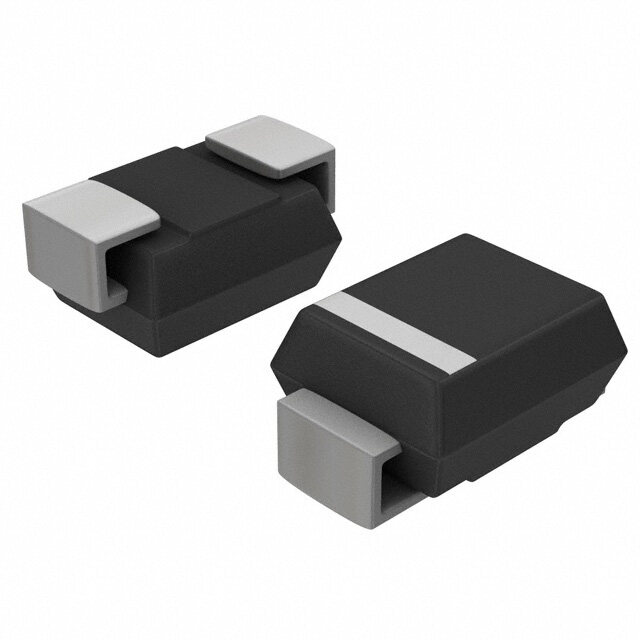
| 描述 | TRIMMER 2K OHM 0.25W SMD |
| 产品分类 | |
| 品牌 | Copal Electronics Inc |
| 数据手册 | |
| 产品图片 |
|
| 产品型号 | ST7ETB202 |
| rohs | 无铅 / 符合限制有害物质指令(RoHS)规范要求 |
| 产品系列 | ST7 |
| 产品目录绘图 |
|
| 产品目录页面 | |
| 其它名称 | ST7ETB202DKR |
| 功率(W) | 0.25W,1/4W |
| 包装 | Digi-Reel® |
| 圈数 | 3 |
| 大小/尺寸 | 方形 - 0.252" 长 x 0.240" 宽 x 0.134" 高(6.40mm x 6.10mm x 3.40mm) |
| 安装类型 | 表面贴装 |
| 容差 | ±20% |
| 标准包装 | 1 |
| 温度系数 | ±100ppm/°C |
| 电阻(Ω) | 2k |
| 电阻材料 | 金属陶瓷 |
| 端子类型 | 鸥翼型 |
| 调节类型 | 顶部调节 |


- 商务部:美国ITC正式对集成电路等产品启动337调查
- 曝三星4nm工艺存在良率问题 高通将骁龙8 Gen1或转产台积电
- 太阳诱电将投资9.5亿元在常州建新厂生产MLCC 预计2023年完工
- 英特尔发布欧洲新工厂建设计划 深化IDM 2.0 战略
- 台积电先进制程称霸业界 有大客户加持明年业绩稳了
- 达到5530亿美元!SIA预计今年全球半导体销售额将创下新高
- 英特尔拟将自动驾驶子公司Mobileye上市 估值或超500亿美元
- 三星加码芯片和SET,合并消费电子和移动部门,撤换高东真等 CEO
- 三星电子宣布重大人事变动 还合并消费电子和移动部门
- 海关总署:前11个月进口集成电路产品价值2.52万亿元 增长14.8%


PDF Datasheet 数据手册内容提取
ST-7 構造図 ST-7 SURFACE MOUNT CERMET TRIMMERS (3 TURNS) RoHS compliant INTERNAL STRUCTURE !3 1 !2 8 9 !1 !0 3 4 7 6 5 2 Part name Material Flammability 1 Rotor gear Polyphenylenesulphide UL94V-0 ■ FEATURES 2 Base element Ceramic ● RoHS compliant 3 Terminal pin Copper alloy, Sn-Cu-plated ● Fine adjustment is possible — ● Automatic mounting is possible (Taping) 4 Resistive element RuO2 cermet ● Flow/reflow soldering is possible ● Sealed construction (Washable: Refer to page 698.) 5 Electrode Ag-Pd cermet 6 Housing base Polyphenylenesulphide UL94V-0 7 Wiper Multi metal alloy — 8 Shaft Polyphenylenesulphide UL94V-0 9 Housing !0 Shaft “O” ring Silicone rubber UL94HB !1 Base “O” ring !2 Clutch spring Stainless steel — !3 Cover ■ PART NUMBER DESIGNATION S T - 7 E T A 1 k Ω ( 1 0 2 ) Series name Resistance code Terminal pin Resistance value E:Sn-Cu (Lead-free) Form of packaging Product shape (Shape of terminal) T:Taping (Reel) A:J-hook Blank:Bulk in plastic bag B:Gull wing ※Please refer to the LIST OF PART NUMBERS when placing orders.
ST-7 SURFACE MOUNT TRIMMERS ■ LIST OF PART NUMBERS <Nominal resistance values> Form of packaging 50 Ω 100 Ω 200 Ω 500 Ω 1 kΩ 2 kΩ 5 kΩ Adjustment Shape of terminal position Taping (reel) Plastic bag 10 kΩ 20 kΩ 50 kΩ 100 kΩ 200 kΩ 500 kΩ 1 MΩ Fig. 1 A( J-hook ) ST-7ETA ST-7EA ※The above part numbers are all available with the respective combination of Top adjustment <Nominal resistance values> (Fig. 1). B(Gull wing) ST-7ETB ST-7EB ※Verify the above part numbers when placing orders. ※Taping specification is not sold separately and must be purchased in reel units. Pieces in package 500 pcs./reel 50 pcs./pack ■ ELECTRICAL CHARACTERISTICS ■ MECHANICAL CHARACTERISTICS Nominal resistance range 50 Ω ~ 1 MΩ Mechanical turn 3 turns Operating torque 5 mN·m {51 gf·cm} maximum Resistance tolerance ± 20 % Mechanical stop Clutch action Power ratings 0.25 W (70 °C) 0 W (125 °C) Rotational life 100 cycles [ΔR/R ≦ ± (2 Ω +3 %)] Resistance law Linear law Thrust to shaft 5 N {0.51 kgf} minimum Maximum input DC200 V or power rating, whichever is smaller voltage Solderability 245 ± 3 °C, 2 ~ 3 s Maximum wiper current 100 mA or power rating, whichever is smaller Shear (Adhesion) 5 N {0.51 kgf} 10 s Effective electrical 2.5 turns Substrate bending Width 90 mm, bend 3 mm, 5 s, 1 time turn Pull-off strength 5 N {0.51 kgf} 10 s End resistance 1 % or 2 Ω, whichever is greater { }:Reference only C.R.V. 1 % or 3 Ω, whichever is greater Operating temp. −55 ~ 125 °C range ■ ENVIRONMENTAL CHARACTERISTICS 50 Ω : ± 250 10-6/°C maximum Temp. coefficient 100 Ω ~ 1 MΩ : ± 100 10-6/°C maximum Test item Test conditions Specifications Insulation resistance 1000 MΩ minimum (DC500 V) Thermal shock −65 ~ 125 °C (0.5 h), 5 cycles [Δ[S.RS/.R ≦ ≦ 1 2% %]] Dielectric strength AC600 V, 60 s Humidity −101 ~0 6c5y c°lCes (,8 204 ~0 9h8 %), [ΔR/R ≦ 2 %] Net weight Approx. 0.25 g 981 m/s2, 6 ms Shock 6 directions for 3 times each [ΔR/R ≦ 1 %] (Amplitude) 1.52 mm or [S.S. ≦ 1 %] Vibration (Acceleration) 196 m/s2, 10 ~ 2000 Hz, 3 directions, 12 times each 〈Reflow profile for soldering heat evaluation〉 Load life 70 °C, 0.25 W, 1000 h [ΔR/R ≦ 3 %] [S.S. ≦ 1 %] 2(5℃0) Peak : 250+ 50℃ Low temp. operation −55 °C, 2 h [Δ[S.RS/.R ≦ ≦ 2 2% %]] High temp. exposure 125 °C, 250 h [ΔR/R ≦ 3 %] Over 230 ℃ [S.S. ≦ 2 %] ure 200 180 ℃ Pre Heating Zone Immersion seal 85 °C, 60 s (No conNtinou leoaukss bubbles) at er 150 150 ℃ p Tem 90 ± 30 s Fpolot owf m: o2lt6e0n ±so l3d e°rC, iamsm tehres itoenm fproemra tuhreea din oaf 100 30 ± 10 s ter minal to backside of board, 5 ~ 6 s, two Soldering heat times maximum [ΔR/R ≦ 1 %] Reflow : Peak temperature 255 °C 50 Soldering Zone Heating time (Please refer to the profile below.) 手はんだ Manual soldering:350 ± 10 °C, 3 ~ 4 s Reflow : two times maximum ΔR/R:Change in total resistance S.S. :Setting stability
ST-7 SURFACE MOUNT TRIMMERS ■ MAXIMUM INPUT RATINGS ■ RECOMMENDED P.C.B. PAD OUTLINE DIMENSIONS ● ST-7EA ● ST-7EB (Unit: mm) Nominal resistance Resistance code Maximum input Maximum wiper values (Ω) voltage (V) current (mA) 2 2 50 500 3.53 70.7 100 101 5.00 50.0 200 201 7.07 35.4 2 500 501 11.2 22.4 2 1 k 102 15.8 15.8 ST-7A 外形図 2 k 202 22.4 11.2 0 5 0 5 5 k 502 35.4 7.07 3. 5. 10 k 103 50.0 5.00 20 k 203 70.7 3.54 50 k 503 112 2.24 2 100 k 104 158 1.58 2 200 k 204 200 1.00 1.6 1.6 500 k 504 200 0.40 1.6 1.6 1 M 105 200 0.20 2.35 2.35 Note) The zero point is the center of mounting. ■ OUTLINE DIMENSIONS Unless otherwise specified, tolerance : ± 0.3 (Unit : mm) ST-7B 外形図 ● ST-7EA Top adjustment 1 3 6.4 0.5 W × 1.8 L × 0.5 D CW rotation 1.2 2 1.5 3.4 2 Lead-free Identification mark 5 1. 6.1 06.8–0.5 4.3 1 t = 0.15 0.02 min. 2 – 0.8 3 2.3 Resistance code & Production date code ● ST-7EB Top adjustment n. 0.5 W × 1.8 L × 0.5 D mi 2 6.4 1.5 3.4 0.35 1.2 Lead-free Identification mark 5 1. 1 8 6. 7. 1 t = 0.15 n. 2 – 0.8 3 mi 2.3 0.02 min. 5 3 Resistance code & Production date code 0. ※ The ST-7 series has a different terminal arrange- ment from the ST-32 and ST-4 series. Pay attention to the location of terminals number 1 and 3. (Resistance decreases when the shaft is turned ΔR/R:Change in total resistance CCW.) S.S. :Setting stability
ST-7 SURFACE MOUNT TRIMMERS ■ PACKAGING SPECIFICATIONS <Taping packaging specifications> ● Taping version is packaged in 500 pcs. per reel. Maximum number of consecutive missing pieces = 2 Orders will be accepted for units of 500 pcs., i.e., 500, Leader length and reel dimension are shown in the dia- 1000, 1500 pcs., etc. grams below. ● Taping version is boxed with one reel (500 pcs.). ● EMBOSSED TAPE DIMENSIONS ● REEL DIMENSIONS (Conforms to JIS C 0806-3) (In accordance with EIAJ ET-7200A) (Unit: mm) ST-E7mpTty B TapFililend g Empty ST-7TA Taping 17.4±1 End Head 21±0.8 2±0.5 n. mi 0 40 mm min. 20 pitches min. 5 Direction of feed Leader 400 mm min. 13±0.2 254±2 21.4±1 ● ST-7ETA ● ST-7ETB 1 φ1.50+0.1 12 ±4 0±. 10.1 2 ± 0.1 ± 1.750. 0.4 ± 0.1 I(nSsTt-a7llEaAti)on example φ1.50+0.1 12 ±4 0±. 10.1 2 ± 0.1 ± 1.750.1 0.4 ± 0.1 I(nSsTt-a7llEaBti)on example 1 ± 7.50. 16 ± 7.50.1 16 Direction of feed 5 Direction of feed 5 <Bulk pack packaging specifications> ● Unit of bulk in a plastic bag is 50 pcs. per pack. ● Boxing of bulk in a plastic bag is performed with 200 pcs. per box.