ICGOO在线商城 > 射频/IF 和 RFID > RF 解调器 > SKY73012-11

 Datasheet下载
- 型号: SKY73012-11
- 制造商: SKYWORKS
- 库位|库存: xxxx|xxxx
- 要求:
| 数量阶梯 | 香港交货 | 国内含税 |
| +xxxx | $xxxx | ¥xxxx |
查看当月历史价格
查看今年历史价格
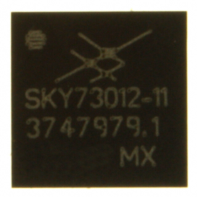
SKY73012-11产品简介:
ICGOO电子元器件商城为您提供SKY73012-11由SKYWORKS设计生产,在icgoo商城现货销售,并且可以通过原厂、代理商等渠道进行代购。 SKY73012-11价格参考¥询价-¥询价。SKYWORKSSKY73012-11封装/规格:RF 解调器, RF Demodulator IC 400MHz ~ 3.9GHz 32-TFLGA Exposed Pad。您可以下载SKY73012-11参考资料、Datasheet数据手册功能说明书,资料中有SKY73012-11 详细功能的应用电路图电压和使用方法及教程。
Skyworks Solutions Inc. 的 SKY73012-11 是一款射频(RF)解调器,主要应用于无线通信系统中,用于将接收到的射频信号转换为基带信号,以便后续处理。

该器件广泛应用于以下场景:

1. 无线基础设施:如蜂窝基站和微波回传系统,用于接收和解调来自移动设备或远程基站的射频信号,实现高效的数据传输。

2. 工业通信设备:在工业自动化和远程监控系统中,作为接收端的核心组件,处理无线传输的数据信号。

3. 宽带接入设备:适用于Wi-Fi 6E、5G Wi-Fi等高速无线接入点设备,提升信号接收灵敏度和稳定性。

4. 测试与测量设备:用于射频测试仪器中,实现对射频信号的精确解调与分析,支持通信设备的研发与维护。

5. 物联网(IoT)网关:在需要多频段、高性能无线连接的IoT网关中,作为关键射频前端组件,提升通信质量。

SKY73012-11具备高线性度、低噪声和良好的频率稳定性,适用于复杂电磁环境下的高性能通信系统。
| 参数 | 数值 |
| 产品目录 | |
| 描述 | IC QUADRATURE DEMOD 32-RFLGA |
| 产品分类 | |
| LO频率 | 400MHz ~ 3.9GHz |
| 品牌 | Skyworks Solutions Inc |
| 数据手册 | |
| 产品图片 |
|
| P1dB | 12.5dBm |
| 产品型号 | SKY73012-11 |
| RF频率 | 400MHz ~ 3.9GHz |
| rohs | 无铅 / 符合限制有害物质指令(RoHS)规范要求 |
| 产品系列 | - |
| 产品目录绘图 |
|
| 产品目录页面 | |
| 供应商器件封装 | 32-RFLGA™(5x5) |
| 其它名称 | 863-1082-6 |
| 功能 | 解调器 |
| 包装 | Digi-Reel® |
| 噪声系数 | 19dB |
| 增益 | -0.5dB |
| 封装/外壳 | 32-TFLGA 裸露焊盘 |
| 标准包装 | 1 |
| 电压-电源 | 2.7 V ~ 3.6 V |
| 电流-电源 | 75mA |


- 商务部:美国ITC正式对集成电路等产品启动337调查
- 曝三星4nm工艺存在良率问题 高通将骁龙8 Gen1或转产台积电
- 太阳诱电将投资9.5亿元在常州建新厂生产MLCC 预计2023年完工
- 英特尔发布欧洲新工厂建设计划 深化IDM 2.0 战略
- 台积电先进制程称霸业界 有大客户加持明年业绩稳了
- 达到5530亿美元!SIA预计今年全球半导体销售额将创下新高
- 英特尔拟将自动驾驶子公司Mobileye上市 估值或超500亿美元
- 三星加码芯片和SET,合并消费电子和移动部门,撤换高东真等 CEO
- 三星电子宣布重大人事变动 还合并消费电子和移动部门
- 海关总署:前11个月进口集成电路产品价值2.52万亿元 增长14.8%


PDF Datasheet 数据手册内容提取
DATA SHEET SKY73012: 400 – 3900 MHz Direct Quadrature Demodulator Applications Description • WiMAX (802.16) receivers Skyworks SKY73012 is an integrated, broadband, high-dynamic range quadrature demodulator for use in various wireless • CDMA macro and pico base stations communication system applications. The SKY73012 can perform • PCS, DCS, GSM/GPRS, and EDGE receivers quadrature demodulation of RF input signals from 400 to • Third Generation (3G) wireless communications 3900 MHz directly to baseband frequencies. The quadrature outputs are differential and can be directly connected to most • Power amplifier feedback/linearization commonly available A/D converters. • Wireless Local Loops (WLLs) The high dynamic range and second order Input Intercept Point • Wireless Local Area Networks (WLANs) (IIP2) value of the SKY73012 make it ideal for use in direct • RFID readers conversion and low Intermediate Frequency (IF) receivers. Figure 1 shows a functional block diagram for the SKY73012. The device package and pinout for the 32-pin RF Land Grid Array Features (RFLGA) are shown in Figure 2. • High IIP2 and IIP3 • Wideband RF input frequency range (400 to 3900 MHz) Skyworks offers lead (Pb)-free, RoHS (Restriction of • Wideband LO input frequency range (400 to 3900 MHz) Hazardous Substances) compliant packaging. • Integrated LO balun • Integrated LO amplifier • On-chip I/Q phase splitter • Differential IF output supports direct interface to A/D circuitry • AM demodulation immunity • Single +3.0 V supply • RFLGA™ (32 pin, 5 x 5 mm) Pb-free package (MSL3, 260 °C per JEDEC J-STD-020) D D + D – D D N N F N F N N G G R G R G G 32 31 30 29 28 27 26 GND 1 25 GND I+ I– GND 2 24 IFIP GND 3 23 GND VCC 4 22 IFIN VCC 5 21 GND VCC 6 20 IFQP RF+ 0 RF– 90 GND 7 19 GND LO 180 GND 8 18 IFQN GND 9 17 GND 10 11 12 13 14 15 16 D D D D O D D N N N N L N N G G G G G G C1468 Q+ Q– C1469 Figure 2. SKY73012 Pinout– 32-Pin RFLGA Package (Top View) Figure 1. SKY73012 Functional Block Diagram Skyworks Solutions, Inc. • Phone [781] 376-3000 • Fax [781] 376-3100 • sales@skyworksinc.com • www.skyworksinc.com 200473B • Skyworks Proprietary and Confidential information • Products and Product Information are Subject to Change Without Notice • January 12, 2007 1
DATA SHEET • SKY73012 DEMODULATOR Table 1. SKY73012 Signal Descriptions Pin # Name Description Pin # Name Description 1 GND Ground 17 GND Ground 2 GND Ground 18 IFQN Negative quadrature IF output 3 GND Ground 19 GND Ground 4 VCC +3 VDC supply 20 IFQP Positive quadrature IF output 5 VCC +3 VDC supply 21 GND Ground 6 VCC +3 VDC supply 22 IFIN Negative in-phase IF output 7 GND Ground 23 GND Ground 8 GND Ground 24 IFIP Positive in-phase IF output 9 GND Ground 25 GND Ground 10 GND Ground 26 GND Ground 11 GND Ground 27 GND Ground 12 GND Ground 28 RF– Negative RF input 13 GND Ground 29 GND Ground 14 LO LO input 30 RF+ Positive RF input 15 GND Ground 31 GND Ground 16 GND Ground 32 GND Ground Electrical and Mechanical Specifications The SKY73012 is rated to Moisture Sensitivity Level 3 (MSL3) at 260 °C. It can be used for lead or lead-free soldering. For Signal pin assignments and functional pin descriptions are additional information, refer to the Skyworks Application Note, provided in Table 1. The absolute maximum ratings of the PCB Design & SMT Assembly/Rework Guidelines for RFLGA SKY73012 are provided in Table 2 and the recommended Packages, document number 103147. operating conditions provided in Table 3. Electrical characteristics of the SKY73012 are provided in Table 4. Care must be taken when attaching this product, whether it is done manually or in a production solder reflow environment. Typical performance characteristics of the SKY73012 are Production quantities of this product are shipped in a standard illustrated in Figures 3 through 59. tape and reel format. For packaging details, refer to the Skyworks Figure 67 provides the package dimensions for the 32-pin RFLGA, Application Note Tape and Reel, document number 101568. and Figure 68 provides the tape and reel dimensions. Electrostatic Discharge (ESD) Sensitivity Package and Handling Information The SKY73012 is a static-sensitive electronic device. Do not Since the device package is sensitive to moisture absorption, it is operate or store near strong electrostatic fields. Take proper ESD baked and vacuum packed before shipping. Instructions on the precautions. shipping container label regarding exposure to moisture after the container seal is broken must be followed. Otherwise, problems related to moisture absorption may occur when the part is subjected to high temperature during solder assembly. Skyworks Solutions, Inc. • Phone [781] 376-3000 • Fax [781] 376-3100 • sales@skyworksinc.com • www.skyworksinc.com 2 January 12, 2007 • Skyworks Proprietary and Confidential information • Products and Product Information are Subject to Change Without Notice • 200473B
DATA SHEET • SKY73012 DEMODULATOR Table 2. SKY73012 Absolute Maximum Ratings (TA = +25 °C, unless otherwise noted) Parameter Symbol Min Typical Max Units +3 V supply voltage VCC 2.7 3.6 V Power dissipation PD 210 320 mW RF input power PRFIN 18 dBm LO input power PLOIN 0 6 dBm Operating case temperature TOPR –40 +85 °C Storage case temperature TSTG –40 0 +125 °C Note: Exposure to maximum rating conditions for extended periods may reduce device reliability. There is no damage to device with only one parameter set at the limit and all other parameters set at or below their nominal values. Table 3. SKY73012 Recommended Operating Conditions Parameter Symbol Min Typical Max Units +3 V supply voltage VCC 2.7 3.0 3.3 V Current consumption ICC 75 mA Operating case temperature TOPR –40 +85 °C Table 4. SKY73012 Electrical Characteristics (1 of 3) (VCC = 3 V, IF = 10 MHz, LO Input Power = 0 dBm, TC = 25 °C, unless otherwise noted) Parameter Symbol Test Conditions Min Typical Max Units RF input frequency range 400 3900 MHz LO input frequency range 400 3900 MHz IF frequency range DC 250 MHz I/Q amplitude imbalance –0.3 +0.3 dB I/Q phase error –3 +1 +3 deg IF output impedance (Note 1) 500 Ω IF output DC level Over process and 0.95 1.20 1.55 V operating temperature 900 MHz RF Input (Note 2) Voltage conversion gain 1 dB Power conversion gain –10.5 –9.0 dB SSB Noise Figure NF 15.5 17.5 dB 2nd Order Input Intercept Point IIP2 55 60 dBm 3rd Order Input Intercept Point IIP3 26 29 dBm Input 1 dB compression 10.5 12 dBm RF input VSWR With external matching 1.5:1 components, ZO = 50 Ω LO input VSWR With external matching 1.5:1 components, ZO = 50 Ω IF output noise floor –167 dBm/Hz RF to LO isolation 68 dB LO to IF isolation 44 dB Skyworks Solutions, Inc. • Phone [781] 376-3000 • Fax [781] 376-3100 • sales@skyworksinc.com • www.skyworksinc.com 200473B • Skyworks Proprietary and Confidential information • Products and Product Information are Subject to Change Without Notice • January 12, 2007 3
DATA SHEET • SKY73012 DEMODULATOR Table 4. SKY73012 Electrical Characteristics (2 of 3) (VCC = 3 V, IF = 10 MHz, LO Input Power = 0 dBm, TC = 25 °C, unless otherwise noted) Parameter Symbol Test Conditions Min Typical Max Units 1900 MHz RF Input (Note 2) Voltage conversion gain 1.1 dB Power conversion gain –10.5 –8.9 dB SSB Noise Figure NF 16.0 17.5 dB 2nd Order Input Intercept Point IIP2 49 54 dBm 3rd Order Input Intercept Point IIP3 23 25 dBm Input 1 dB compression 10.0 11.2 dBm RF input VSWR With external matching 1.5:1 components, ZO = 50 Ω LO input VSWR With external matching 1.5:1 components, ZO = 50 Ω IF output noise floor –166 dBm/Hz RF to LO isolation 61 dB LO to IF isolation 31 dB 2600 MHz RF Input (Note 2) Voltage conversion gain –0.5 dB Power conversion gain –11.5 –10.5 dB SSB Noise Figure NF 18.5 20.0 dB 2nd Order Input Intercept Point IIP2 43 48 dBm 3rd Order Input Intercept Point IIP3 23.0 25.5 dBm Input 1 dB compression 12.0 13.5 dBm RF input VSWR With external matching 1.5:1 components, ZO = 50 Ω LO input VSWR With external matching 2.5:1 components, ZO = 50 Ω IF output noise floor –166 dBm/Hz RF to LO isolation 55 dB LO to IF isolation 30 dB Skyworks Solutions, Inc. • Phone [781] 376-3000 • Fax [781] 376-3100 • sales@skyworksinc.com • www.skyworksinc.com 4 January 12, 2007 • Skyworks Proprietary and Confidential information • Products and Product Information are Subject to Change Without Notice • 200473B
DATA SHEET • SKY73012 DEMODULATOR Table 4. SKY73012 Electrical Characteristics (2 of 3) (VCC = 3 V, IF = 10 MHz, LO Input Power = 0 dBm, TC = 25 °C, unless otherwise noted) Parameter Symbol Test Conditions Min Typical Max Units 3600 MHz RF Input (Note 2) Voltage conversion gain –0.5 dB Power conversion gain –11.5 –10.5 dB SSB Noise Figure NF 19.0 20.5 dB 2nd Order Input Intercept Point (Note 3) IIP2 44 50 dBm 3rd Order Input Intercept Point (Note 3) IIP3 19.0 21.5 dBm Input 1 dB compression 11.5 12.5 dBm RF input VSWR With external matching 1.5:1 components, ZO = 50 Ω LO input VSWR With external matching 3.0:1 components, ZO = 50 Ω IF output noise floor –165 dBm/Hz RF to LO isolation 58 dB LO to IF isolation 24 dB Note 1: Differential IFI and IFQ output impedance without the use of a 9:1 impedance ratio balun. Note 2: The recommended LO input power level can vary from –3 dBm to +3 dBm for the 900, 1900, and 2600 MHz RF input frequencies. Above 3300 MHz, better performance is achieved by using a higher LO input power level such as +5 dBm. Note 3: When a +5 dBm LO input power level is applied at 3600 MHz, the typical IIP2 value is 51 dBm and the typical IIP3 value is 22.5 dBm. Skyworks Solutions, Inc. • Phone [781] 376-3000 • Fax [781] 376-3100 • sales@skyworksinc.com • www.skyworksinc.com 200473B • Skyworks Proprietary and Confidential information • Products and Product Information are Subject to Change Without Notice • January 12, 2007 5
DATA SHEET • SKY73012 DEMODULATOR –7.0 –7.0 –7.5 –7.5 –8.0 –8.0 –8.5 –8.5 B) –9.0 B) –9.0 d d n ( –9.5 n ( –9.5 ai ai G –10.0 G –10.0 –10 dBm –40 oC –10.5 0 dBm –10.5 +25 oC –11.0 +3 dBm –11.0 +85 oC –11.5 –11.5 –12.0 –12.0 800 850 900 950 1000 800 850 900 950 1000 Frequency (MHz) Frequency (MHz) Figure 3. Power Conversion Gain vs Frequency and LO Power Figure 4 Power Conversion Gain vs Frequency and Temperature @ 900 MHz @ 900 MHz –7.0 20 –7.5 19 –8.0 18 –8.5 17 ain (dB) ––99..05 NF (dB) 1165 G –10.0 14 –10.5 2.7 V 13 –10 dBm 3.0 V 0 dBm –11.0 3.3 V 12 +3 dBm –11.5 11 –12.0 10 800 850 900 950 1000 800 850 900 950 1000 Frequency (MHz) Frequency (MHz) Figure 5. Power Conversion Gain vs Frequency and Figure 6. Noise Figure vs Frequency and LO Power @ 900 MHz Supply Voltage @ 900 MHz 20 20 19 19 18 18 17 17 NF (dB) 1165 NF (dB) 1165 14 14 13 –40 oC 13 2.7 V +25 oC 3.0 V 12 +85 oC 12 3.3 V 11 11 10 10 800 850 900 950 1000 800 850 900 950 1000 Frequency (MHz) Frequency (MHz) Figure 7. Noise Figure vs Frequency and Temperature @ 900 MHz Figure 8. Noise Figure vs Frequency and Supply Voltage @ 900 MHz Skyworks Solutions, Inc. • Phone [781] 376-3000 • Fax [781] 376-3100 • sales@skyworksinc.com • www.skyworksinc.com 6 January 12, 2007 • Skyworks Proprietary and Confidential information • Products and Product Information are Subject to Change Without Notice • 200473B
DATA SHEET • SKY73012 DEMODULATOR 68 68 67 67 66 66 65 65 m) 64 m) 64 B B 2 (d 63 2 (d 63 IIP 62 IIP 62 61 –10 dBm 61 –40 oC 0 dBm +25 oC 60 +3 dBm 60 +85 oC 59 59 58 58 800 850 900 950 1000 800 850 900 950 1000 Frequency (MHz) Frequency (MHz) Figure 9. IIP2 vs Frequency and LO Power @ 900 MHz Figure 10. IIP2 vs Frequency and Temperature @ 900 MHz 68 34 33 67 32 66 31 65 30 29 IIP2 (dBm) 666432 IIP3 (dBm) 22228765 61 2.7 V 24 60 33..03 VV 2232 –+1003 dddBBBmmm 59 21 58 20 800 850 900 950 1000 800 850 900 950 1000 Frequency (MHz) Frequency (MHz) Figure 11. IIP2 vs Frequency and Supply Voltage @ 900 MHz Figure 12. IIP3 vs Frequency and LO Power @ 900 MHz 34 34 33 33 32 32 31 31 30 30 IIP3 (dBm) 2222298765 IIP3 (dBm) 2222298765 222432 ++–428055 oooCCC 222432 233...703 VVV 21 21 20 20 800 850 900 950 1000 800 850 900 950 1000 Frequency (MHz) Frequency (MHz) Figure 13. IIP3 vs Frequency and Temperature @ 900 MHz Figure 14. IIP3 vs Frequency and Supply Voltage @ 900 MHz Skyworks Solutions, Inc. • Phone [781] 376-3000 • Fax [781] 376-3100 • sales@skyworksinc.com • www.skyworksinc.com 200473B • Skyworks Proprietary and Confidential information • Products and Product Information are Subject to Change Without Notice • January 12, 2007 7
DATA SHEET • SKY73012 DEMODULATOR 15.0 15.0 14.5 14.5 14.0 14.0 13.5 13.5 m) 13.0 m) 13.0 P1dB (dB 1122..50 P1dB (dB 1122..50 11.5 –10 dBm 11.5 –40 oC 11.0 +03 ddBBmm 11.0 ++2855 ooCC 10.5 10.5 10.0 10.0 800 850 900 950 1000 800 850 900 950 1000 Frequency (MHz) Frequency (MHz) Figure 15. Input 1 dB Compression Point vs Frequency and LO Figure 16 Input 1 dB Compression Point vs Frequency and Power @ 900 MHz Temperature @ 900 MHz 15.0 80 14.5 2.7 V 3.0 V 78 14.0 3.3 V 76 +–4205 ooCC 13.5 B) 74 +85 oC Bm) 13.0 on (d 72 P1dB (d 1122..50 O Isolati 7608 L 11.5 F to 66 11.0 R 64 10.5 62 10.0 60 800 850 900 950 1000 800 850 900 950 1000 Frequency (MHz) Frequency (MHz) Figure 17. Input 1 dB Compression Point vs Frequency and Figure 18. RF to LO Isolation vs Frequency and Temperature Supply Voltage @ 900 MHz @ 900 MHz 60 +0.30 5586 ++–428055 oooCCC ++00..2250 ++–428055 oooCCC B) 54 dB) +0.15 solation (d 5520 mbalance ( ++00..10050 LO to IF I 444864 mplitude I –––000...101055 A –0.20 42 –0.25 40 –0.30 800 850 900 950 1000 800 850 900 950 1000 Frequency (MHz) Frequency (MHz) Figure 19. LO to IF Isolation vs Frequency and Temperature Figure 20. IQ Amplitude Imbalance vs Frequency and @ 900 MHz Temperature @ 900 MHz Skyworks Solutions, Inc. • Phone [781] 376-3000 • Fax [781] 376-3100 • sales@skyworksinc.com • www.skyworksinc.com 8 January 12, 2007 • Skyworks Proprietary and Confidential information • Products and Product Information are Subject to Change Without Notice • 200473B
DATA SHEET • SKY73012 DEMODULATOR +3.0 –7.0 +2.5 –7.5 +2.0 –8.0 +1.5 s) –8.5 ee +1.0 Phase Error (degr +––––01012.....500550 ++–428055 oooCCC Gain (dB) –––––11199010.....05005 –+1003 dddBBBmmm –11.5 –2.5 –3.0 –12.0 800 850 900 950 1000 1800 1850 1900 1950 2000 Frequency (MHz) Frequency (MHz) Figure 21. I/Q Phase Error vs Frequency and Temperature Figure 22. Power Conversion Gain vs Frequency and LO Power @ 900 MHz @ 1900 MHz –7.0 –7.0 –7.5 –7.5 –8.0 –8.0 –8.5 –8.5 Gain (dB) –––1990...050 Gain (dB) –––1990...050 –10.5 –10.5 2.7 V –40 oC 3.0 V –11.0 +25 oC –11.0 3.3 V –11.5 +85 oC –11.5 –12.0 –12.0 1800 1850 1900 1950 2000 1800 1850 1900 1950 2000 Frequency (MHz) Frequency (MHz) Figure 23. Power Conversion Gain vs Frequency and Temperature Figure 24. Power Conversion Gain vs Frequency and @ 1900 MHz Supply Voltage @ 1900 MHz 20 20 19 19 18 18 Noise Figure (dB) 1111176543 Noise Figure (dB) 1111176543 –40 oC –10 dBm +25 oC 12 0 dBm 12 +85 oC +3 dBm 11 11 10 10 1800 1850 1900 1950 2000 1800 1850 1900 1950 2000 Frequency (MHz) Frequency (MHz) Figure 25. Noise Figure vs Frequency and LO Power @ 1900 MHz Figure 26. Noise Figure vs Frequency and Temperature @ 1900 MHz Skyworks Solutions, Inc. • Phone [781] 376-3000 • Fax [781] 376-3100 • sales@skyworksinc.com • www.skyworksinc.com 200473B • Skyworks Proprietary and Confidential information • Products and Product Information are Subject to Change Without Notice • January 12, 2007 9
DATA SHEET • SKY73012 DEMODULATOR 20 70 19 68 –10 dBm 0 dBm 18 66 +3 dBm 17 64 B) se Figure (d 111654 IIP2 (dBm) 665208 Noi 13 2.7 V 56 12 3.0 V 54 3.3 V 11 52 10 50 1800 1850 1900 1950 2000 1800 1850 1900 1950 2000 Frequency (MHz) Frequency (MHz) Figure 27. Noise Figure vs Frequency and Supply Voltage Figure 28. IIP2 vs Frequency and LO Power @ 1900 MHz @ 1900 MHz 70 70 68 –40 oC 68 +25 oC 66 +85 oC 66 64 64 m) 62 m) 62 dB 60 dB 60 2 ( 2 ( P 58 P 58 II II 56 56 2.7 V 54 54 3.0 V 52 52 3.3 V 50 50 1800 1850 1900 1950 2000 1800 1850 1900 1950 2000 Frequency (MHz) Frequency (MHz) Figure 29. IIP2 vs Frequency and Temperature @ 1900 MHz Figure 30. IIP2 vs Frequency and Supply Voltage @ 1900 MHz 34 34 333321 –+1003 dddBBBmmm 333321 ++–428055 oooCCC 30 30 29 29 m) 28 m) 28 dB 27 dB 27 3 ( 26 3 ( 26 P P II 25 II 25 24 24 23 23 22 22 21 21 20 20 1800 1850 1900 1950 2000 1800 1850 1900 1950 2000 Frequency (MHz) Frequency (MHz) Figure 31. IIP3 vs Frequency and LO Power @ 1900 MHz Figure 32. IIP3 vs Frequency and Temperature @ 1900 MHz Skyworks Solutions, Inc. • Phone [781] 376-3000 • Fax [781] 376-3100 • sales@skyworksinc.com • www.skyworksinc.com 10 January 12, 2007 • Skyworks Proprietary and Confidential information • Products and Product Information are Subject to Change Without Notice • 200473B
DATA SHEET • SKY73012 DEMODULATOR 34 15 33 2.7 V 14 32 3.0 V 31 3.3 V 13 30 12 29 m) 28 m) 11 IIP3 (dB 222675 P1dB (dB 109 24 8 –10 dBm 23 7 0 dBm 22 +3 dBm 21 6 20 5 1800 1850 1900 1950 2000 1800 1850 1900 1950 2000 Frequency (MHz) Frequency (MHz) Figure 33. IIP3 vs Frequency and Supply Voltage @ 1900 MHz Figure 34. Input 1 dB Compression Point vs Frequency and LO Power @ 1900 MHz 15 15 14 14 13 13 12 12 m) 11 m) 11 B B B (d 10 B (d 10 P1d 9 P1d 9 8 –40 oC 8 +25 oC 2.7 V 7 +85 oC 7 3.0 V 3.3 V 6 6 5 5 1800 1850 1900 1950 2000 1800 1850 1900 1950 2000 Frequency (MHz) Frequency (MHz) Figure 35. Input 1 dB Compression Point vs Frequency and Figure 36. Input 1 dB Compression Point vs Frequency and Temperature @ 1900 MHz Supply Voltage @ 1900 MHz 70 55 68 53 66 51 RF to LO Isolation (dB) 666555420846 ++–428055 oooCCC LO to IF Isolation (dB) 444434975391 +–4205 ooCC 52 37 +85 oC 50 35 1800 1850 1900 1950 2000 1800 1850 1900 1950 2000 Frequency (MHz) Frequency (MHz) Figure 37. RF to LO Isolation vs Frequency and Temperature Figure 38. LO to IF Isolation vs Frequency and Temperature @ 1900 MHz @ 1900 MHz Skyworks Solutions, Inc. • Phone [781] 376-3000 • Fax [781] 376-3100 • sales@skyworksinc.com • www.skyworksinc.com 200473B • Skyworks Proprietary and Confidential information • Products and Product Information are Subject to Change Without Notice • January 12, 2007 11
DATA SHEET • SKY73012 DEMODULATOR 0.30 3.0 0.25 2.5 B) 0.20 2.0 alance (d 000...110505 egrees) 110...505 b d I/Q Amplitude Im ––––0000....101200550 ++–428055 oooCCC Phase Error ( ––––0012....01550 ++–428055 oooCCC –0.25 –2.5 –0.30 –3.0 1800 1850 1900 1950 2000 1800 1850 1900 1950 2000 Frequency (MHz) Frequency (MHz) Figure 39. I/Q Amplitude Imbalance vs Frequency and Figure 40. I/Q Phase Error vs Frequency and Temperature Temperature @ 1900 MHz @ 1900 MHz –8.0 –8.0 –8.5 –10 dBm –8.5 –40 oC 0 dBm +25 oC –9.0 +3 dBm –9.0 +85 oC –9.5 –9.5 –10.0 –10.0 Gain (dB) ––1101..50 Gain (dB) ––1101..50 –11.5 –11.5 –12.0 –12.0 –12.5 –12.5 –13.0 –13.0 2500 2550 2600 2650 2700 2500 2550 2600 2650 2700 Frequency (MHz) Frequency (MHz) Figure 41. Power Conversion Gain vs Frequency and LO Power Figure 42. Power Conversion Gain vs Frequency and Temperature @ 2600 MHz @ 2600 MHz –8.0 22 –8.5 2.7 V 21 3.0 V –9.0 3.3 V 20 –9.5 19 Gain (dB) –––111001...050 e Figure (dB) 111876 s –11.5 Noi 15 –10 dBm –12.0 14 0 dBm –12.5 13 +3 dBm –13.0 12 2500 2550 2600 2650 2700 2500 2550 2600 2650 2700 Frequency (MHz) Frequency (MHz) Figure 43. Power Conversion Gain vs Frequency and Figure 44. Noise Figure vs Frequency and LO Power @ 2600 MHz Supply Voltage @ 2600 MHz Skyworks Solutions, Inc. • Phone [781] 376-3000 • Fax [781] 376-3100 • sales@skyworksinc.com • www.skyworksinc.com 12 January 12, 2007 • Skyworks Proprietary and Confidential information • Products and Product Information are Subject to Change Without Notice • 200473B
DATA SHEET • SKY73012 DEMODULATOR 22 22 21 21 20 20 Noise Figure (dB) 1111198765 –40 oC Noise Figure (dB) 1111198765 2.7 V 14 ++2855 ooCC 14 33..03 VV 13 13 12 12 2500 2550 2600 2650 2700 2500 2550 2600 2650 2700 Frequency (MHz) Frequency (MHz) Figure 45. Noise Figure vs Frequency and Temperature Figure 46. Noise Figure vs Frequency and Supply Voltage @ 2600 MHz @ 2600 MHz 58 58 56 56 54 54 52 52 m) 50 m) 50 B B d 48 d 48 2 ( 2 ( IIP 46 –10 dBm IIP 46 44 0 dBm 44 –40 oC 42 +3 dBm 42 ++2855 ooCC 40 40 38 38 2500 2550 2600 2650 2700 2500 2550 2600 2650 2700 Frequency (MHz) Frequency (MHz) Figure 47. IIP2 vs Frequency and LO Power @ 2600 MHz Figure 48. IIP2 vs Frequency and Temperature @ 2600 MHz 58 30 56 29 28 54 27 52 26 25 Bm) 50 Bm) 24 2 (d 48 3 (d 23 IIP 46 IIP 2221 44 2.7 V 20 –10 dBm 42 3.0 V 19 0 dBm 3.3 V 18 +3 dBm 40 17 38 16 2500 2550 2600 2650 2700 2500 2550 2600 2650 2700 Frequency (MHz) Frequency (MHz) Figure 49. IIP2 vs Frequency and Supply Voltage @ 2600 MHz Figure 50. IIP3 vs Frequency and LO Power @ 2600 MHz Skyworks Solutions, Inc. • Phone [781] 376-3000 • Fax [781] 376-3100 • sales@skyworksinc.com • www.skyworksinc.com 200473B • Skyworks Proprietary and Confidential information • Products and Product Information are Subject to Change Without Notice • January 12, 2007 13
DATA SHEET • SKY73012 DEMODULATOR 30 30 29 29 28 28 27 27 26 26 25 25 Bm) 24 Bm) 24 P3 (d 2223 P3 (d 2223 II 21 II 21 20 –40 oC 20 1189 ++2855 ooCC 1189 233...703 VVV 17 17 16 16 2500 2550 2600 2650 2700 2500 2550 2600 2650 2700 Frequency (MHz) Frequency (MHz) Figure 51. IIP3 vs Frequency and Temperature @ 2600 MHz Figure 52. IIP3 vs Frequency and Supply Voltage @ 2600 MHz 15.0 15.0 14.5 14.5 14.0 14.0 13.5 13.5 P1dB (dBm) 111322...050 P1dB (dBm) 111322...050 11.5 –10 dBm 11.5 –40 oC 11.0 +03 ddBBmm 11.0 ++2855 ooCC 10.5 10.5 10.0 10.0 2500 2550 2600 2650 2700 2500 2550 2600 2650 2700 Frequency (MHz) Frequency (MHz) Figure 53. Input 1 dB Compression Point vs Frequency and LO Figure 54. Input 1 dB Compression Point vs Frequency and Power @ 2600 MHz Temperature @ 2600 MHz 15.0 65 14.5 63 –40 oC 14.0 61 ++2855 ooCC 13.5 dB) 59 dBm) 13.0 ation ( 57 B ( 12.5 sol 55 P1d 12.0 LO I 53 o 11.5 F t 51 2.7 V R 11.0 3.0 V 49 3.3 V 10.5 47 10.0 45 2500 2550 2600 2650 2700 2500 2550 2600 2650 2700 Frequency (MHz) Frequency (MHz) Figure 55. Input 1 dB Compression Point vs Frequency and Figure 56. RF to LO Isolation vs Frequency and Temperature Supply Voltage @ 2600 MHz @ 2600 MHz Skyworks Solutions, Inc. • Phone [781] 376-3000 • Fax [781] 376-3100 • sales@skyworksinc.com • www.skyworksinc.com 14 January 12, 2007 • Skyworks Proprietary and Confidential information • Products and Product Information are Subject to Change Without Notice • 200473B
DATA SHEET • SKY73012 DEMODULATOR 50 0.30 ation (dB) 44448642 ++–428055 oooCCC mbalance (dB) 00000.....2211050505 ++–428055 oooCCC sol 40 e I 0 O to IF I 3386 mplitud ––00..1005 L A –0.15 34 I/Q –0.20 32 –0.25 30 –0.30 2500 2550 2600 2650 2700 2500 2550 2600 2650 2700 Frequency (MHz) Frequency (MHz) Figure 57. LO to IF Isolation vs Frequency and Temperature Figure 58. I/Q Amplitude Imbalance vs Frequency and @ 2600 MHz Temperature @ 2600 MHz 3.0 2.5 2.0 s) 1.5 e gre 1.0 de 0.5 or ( 0 e Err –0.5 as –1.0 –40 oC Ph –1.5 ++2855 ooCC –2.0 –2.5 –3.0 2500 2550 2600 2650 2700 Frequency (MHz) Figure 59. I/Q Phase Error vs Frequency and Temperature @ 2600 MHz Skyworks Solutions, Inc. • Phone [781] 376-3000 • Fax [781] 376-3100 • sales@skyworksinc.com • www.skyworksinc.com 200473B • Skyworks Proprietary and Confidential information • Products and Product Information are Subject to Change Without Notice • January 12, 2007 15
DATA SHEET • SKY73012 DEMODULATOR Evaluation Board Description 4. The RF input must be driven differentially. A 1:1 impedance ratio balun is recommended with a center tap on the The SKY73012 Evaluation Board is used to test the performance secondary side that is DC grounded. of the SKY73012 direct quadrature demodulator. There are three Evaluation Boards for this device, each configured for a specific Testing Procedure frequency range. Each of these boards is described by the following Figures and Tables: Use the following procedure to set up the SKY73012 Evaluation Board for testing. Refer to Figure 66 for guidance: • 800 to 1000 MHz: Figure 60 (schematic), Table 5 (component values), and Figure 61 (assembly diagram) 1. Connect a +3.0 VDC power supply using an insulated supply cable. If available, enable the current limiting function of the • 1800 to 3900 MHz: Figure 62 (schematic), Table 6 (component power supply to 100 mA. values), and Figure 63 (assembly diagram) 2. Connect a signal generator to the RF signal input port. Set it to • Custom Frequency: Figure 64 (schematic), Table 7 (component the desired RF frequency at a power level of 0 dBm to the values), and Figure 65 (assembly diagram) Evaluation Board but do NOT enable the RF signal. Circuit Design Considerations 3. Connect a signal generator to the LO signal input port. Set to the desired LO frequency at a power level of 0 dBm, but do The following design considerations are general in nature and not enable. must be followed regardless of final use or configuration. 4. Connect a spectrum analyzer to the IFI signal output port and 1. Paths to ground should be made as short as possible. terminate the IFQ signal input port in 50 Ω. 2. The ground pad of the SKY73012 direct quadrature 5. Enable the power supply. demodulator has special electrical and thermal grounding requirements. This pad is the main thermal conduit for heat 6. Enable the LO input signal. dissipation. Since the circuit board acts as the heat sink, it 7. Enable the RF signal. must shunt as much heat as possible from the device. As 8. Take measurements and repeat these steps for channel Q. such, design the connection to the ground pad to dissipate the maximum wattage produced to the circuit board. CAUTION: If any of the input signals exceed the rated maximum 3. Two external output bypass capacitors are required on the values, the SKY73012 Evaluation Board can be VCC pin. The values of these capacitors will change with permanently damaged. respect to the desired RF frequency. One capacitor should be used for low frequency bypassing and the other capacitor for high frequency bypassing. Special attention should be given so that the smaller value capacitor does not go into self- resonance at the desired RF frequency. Skyworks Solutions, Inc. • Phone [781] 376-3000 • Fax [781] 376-3100 • sales@skyworksinc.com • www.skyworksinc.com 16 January 12, 2007 • Skyworks Proprietary and Confidential information • Products and Product Information are Subject to Change Without Notice • 200473B
DATA SHEET • SKY73012 DEMODULATOR 1 5 2 1 T1 2 J1 4 3 6 1 J2 2-Pin Header SMA C1 33 pF 32 31 30 29 28 27 26 1 GND GND GND RF+ GND RF– GND GND GND 25 T2 C2 2 GND IFIP 24 3 6 I_IF 1 J3 1000 pF SMA 3 23 2 GND GND 4 22 1 4 VCC IFIN 5 U1 21 VCC GND 6 20 3 T3 6 Q_IF 1 J4 VCC IFQP SMA 7 19 2 GND GND 8 GND IFQN 18 1 4 9 17 GND GND D D D D D D GN GN GN GN LO GN GN 10 11 12 13 14 15 16 R1 0 Ω 1 J5 SMA S181 Figure 60. SKY73012 Evaluation Board Schematic (800 to 1000 MHz) Table 5. SKY73012 Evaluation Board Component Values (800 to 1000 MHz) Reference Quantity Value Manufacturer Part Number Designator C1 1 33 pF (0603) C2 1 1000 pF (0603) J1 1 Two-pin header connector J2 1 SMA connector J3 1 SMA connector J4 1 SMA connector J5 1 SMA connector R1 1 0 Ω (0603) T1 1 1:1 (800-1000 MHz) Murata LDB31900M05C-417 T2 1 9:1 Mini-Circuits TCM-9-1 T3 1 9:1 Mini-Circuits TCM-9-1 U1 1 – Skyworks SKY73012-11 Skyworks Solutions, Inc. • Phone [781] 376-3000 • Fax [781] 376-3100 • sales@skyworksinc.com • www.skyworksinc.com 200473B • Skyworks Proprietary and Confidential information • Products and Product Information are Subject to Change Without Notice • January 12, 2007 17
DATA SHEET • SKY73012 DEMODULATOR J3 J4 T2 T3 J2 T1 U1 J5 R1 C2 C1 J1 Component Placement Top Layer Bottom Layer S920 Figure 61. SKY73012 Evaluation Board Assembly Diagram (800 to 1000 MHz) (Top View) Skyworks Solutions, Inc. • Phone [781] 376-3000 • Fax [781] 376-3100 • sales@skyworksinc.com • www.skyworksinc.com 18 January 12, 2007 • Skyworks Proprietary and Confidential information • Products and Product Information are Subject to Change Without Notice • 200473B
DATA SHEET • SKY73012 DEMODULATOR 2, 5 1 1 T1 2 J1 3 4 1 J2 SMA 2-Pin Header C1 33 pF 32 31 30 29 28 27 26 1 GND GND GND RF+ GND RF– GND GND GND 25 T2 C2 2 GND IFIP 24 3 6 I_IF 1 J3 1000 pF SMA 3 23 2 GND GND 4 22 1 4 VCC IFIN 5 U1 21 VCC GND 6 20 3 T3 6 Q_IF 1 J4 VCC IFQP SMA 7 19 2 GND GND 8 GND IFQN 18 1 4 9 17 GND GND D D D D D D GN GN GN GN LO GN GN 10 11 12 13 14 15 16 R1 0 Ω 1 J5 SMA S731 Figure 62. SKY73012 Evaluation Board Schematic (1800 to 3900 MHz) Table 6. SKY73012 Evaluation Board Component Values (1800 to 3900 MHz) Reference Quantity Value Manufacturer Part Number Designator C1 1 33 pF (0603) C2 1 1000 pF (0603) J1 1 Two-pin header connector J2 1 SMA connector J3 1 SMA connector J4 1 SMA connector J5 1 SMA connector R1 1 0 Ω (0603) T1 1 1:1 (1800-2000 MHz), or Murata LDB211G9005C-001 1:1 (2500-2700 MHz), or Murata LDB212G4005C-001 1:1 (3600-3800 MHz) Johanson 3700BL15B050SX T2 1 9:1 Mini-Circuits TCM-9-1 T3 1 9:1 Mini-Circuits TCM-9-1 U1 1 – Skyworks SKY73012-11 Skyworks Solutions, Inc. • Phone [781] 376-3000 • Fax [781] 376-3100 • sales@skyworksinc.com • www.skyworksinc.com 200473B • Skyworks Proprietary and Confidential information • Products and Product Information are Subject to Change Without Notice • January 12, 2007 19
DATA SHEET • SKY73012 DEMODULATOR J2 T1 T2 J3 J1 C1 C2 U1 T3 J4 R1 J5 Component Placement Top Layer Bottom Layer S921 Figure 63. SKY73012 Evaluation Board Assembly Diagram (1800 to 3900 MHz) (Top View) Skyworks Solutions, Inc. • Phone [781] 376-3000 • Fax [781] 376-3100 • sales@skyworksinc.com • www.skyworksinc.com 20 January 12, 2007 • Skyworks Proprietary and Confidential information • Products and Product Information are Subject to Change Without Notice • 200473B
DATA SHEET • SKY73012 DEMODULATOR L1 L2 L3 TBD TBD TBD 1 M/A-COM 2 ETC1-1-13 C3 J1 T1 3.3 pF 2-Pin Header 1 J2 SMA C1 33 pF (5404R23-019) 32 31 30 29 28 27 26 1 GND GND GND RF+ GND RF– GND GND GND 25 100C02 pF 2 GND IFIP 24 IFIP 3 T2 6 I_IF 1 J3 (5404R23-057) SMA 3 23 2 GND GND 4 22 IFIN 1 4 VCC IFIN TCM-9-1 5 U1 21 VCC GND 6 20 IFQP 3 T3 6 Q_IF 1 J4 VCC IFQP SMA 7 19 2 GND GND 8 GND IFQN 18 IFQN 1 4 TCM-9-1 9 17 GND GND D D D D D D GN GN GN GN LO GN GN 10 11 12 13 14 15 16 R1 0 Ω (5424R20-146) 1 J5 SMA S713 Figure 64. SKY73012 Evaluation Board Schematic (Custom Frequency) Table 7. SKY73012 Evaluation Board Component Values (Custom Frequency) (1 of 2) Reference Quantity Value Manufacturer Part Number Designator C1 1 33 pF (0603) C2 1 1000 pF (0603) C3 Adjusted for best match at desired frequency J1 1 Two-pin header connector J2 1 SMA connector J3 1 SMA connector J4 1 SMA connector J5 1 SMA connector L1 1 Adjusted for best match at desired frequency L2 1 Adjusted for best match at desired frequency L3 1 Adjusted for best match at desired frequency Skyworks Solutions, Inc. • Phone [781] 376-3000 • Fax [781] 376-3100 • sales@skyworksinc.com • www.skyworksinc.com 200473B • Skyworks Proprietary and Confidential information • Products and Product Information are Subject to Change Without Notice • January 12, 2007 21
DATA SHEET • SKY73012 DEMODULATOR Table 7. SKY73012 Evaluation Board Component Values (Custom Frequency) (2 of 2) Reference Quantity Value Manufacturer Part Number Designator R1 1 0 Ω (0603) T1 1 1:1 (4.5-3000 MHz), M/A-COM ETC1-1-13 T2 1 9:1 Mini-Circuits TCM-9-1 T3 1 9:1 Mini-Circuits TCM-9-1 U1 1 – Skyworks SKY73012-11 J3 J4 T2 T3 T1 R1 C3 L1 U1 J5 J2 L2 L3 C2 C1 J1 Component Placement Top Layer Bottom Layer S922 Figure 65. SKY73012 Evaluation Board Assembly Diagram (Custom Frequency) (Top View) Skyworks Solutions, Inc. • Phone [781] 376-3000 • Fax [781] 376-3100 • sales@skyworksinc.com • www.skyworksinc.com 22 January 12, 2007 • Skyworks Proprietary and Confidential information • Products and Product Information are Subject to Change Without Notice • 200473B
DATA SHEET • SKY73012 DEMODULATOR Power Supply VCC GND Spectrum IFI Analyzer Signal RF Generator SKY73012 IFQ Evaluation Board 50 Ω LO Signal Generator S714 Figure 66. SKY73012 Evaluation Board Testing Configuration 5.04 ± 0.05 Pin #1 Indicator Solder Mask Pin #1 Indicator Pin #1 Ground Pad 0.5 ± 0.05 5.04 0.5 Detail A ∅2.0 Top View Bottom View Solder Mask Exposed Metal 0.38 ± 0.05 (32x) ± 0.1 1.0 0.3 ± 0.02 0.05 Ref. (32x) Side View Package Edge 0.4 ± 0.05 (32x) All measurements are in millimeters Detail A C1285a Figure 67. SKY73012 32-Pin RFLGA Package Dimensions Skyworks Solutions, Inc. • Phone [781] 376-3000 • Fax [781] 376-3100 • sales@skyworksinc.com • www.skyworksinc.com 200473B • Skyworks Proprietary and Confidential information • Products and Product Information are Subject to Change Without Notice • January 12, 2007 23
DATA SHEET • SKY73012 DEMODULATOR 2.00 ± 0.05 ∅1.55 ± 0.05 8.00 4.00 0.30 ± 0.05 B 1.75 ± 0.10 Pin #1 Indicator A A 5.50 ± 0.05 ± 0.30 5.35 12.00 5o Max. B ∅1.50 Min. 1.70 5.35 B 5o Max. Notes: 1. Carrier tape: black conductive polystyrene 2. Cover tape material: transparent conductive PSA 3. Cover tape size: 9.3 mm width 4. All dimensions are in millimeters A S461 Figure 68. SKY73012 32-Pin RFLGA Tape and Reel Dimensions Skyworks Solutions, Inc. • Phone [781] 376-3000 • Fax [781] 376-3100 • sales@skyworksinc.com • www.skyworksinc.com 24 January 12, 2007 • Skyworks Proprietary and Confidential information • Products and Product Information are Subject to Change Without Notice • 200473B
DATA SHEET • SKY73012 DEMODULATOR Ordering Information Model Name Manufacturing Part Number Evaluation Kit Part Number SKY73012 400-3900 MHz Direct Quadrature Modulator SKY73012-11 (Pb-free package) TW16-D151-001 (800 to 1000 MHz) TW16-D166-001 (1800 to 2000 MHz) TW16-D167-001 (2400 to 2700 MHz) TW16-D168-001 (3200 to 3900 MHz) TW16-D171-001 (Custom Frequency) Copyright © 2006, 2007 Skyworks Solutions, Inc. All Rights Reserved. Information in this document is provided in connection with Skyworks Solutions, Inc. (“Skyworks”) products or services. These materials, including the information contained herein, are provided by Skyworks as a service to its customers and may be used for informational purposes only by the customer. Skyworks assumes no responsibility for errors or omissions in these materials or the information contained herein. Skyworks may change its documentation, products, services, specifications or product descriptions at any time, without notice. Skyworks makes no commitment to update the materials or information and shall have no responsibility whatsoever for conflicts, incompatibilities, or other difficulties arising from any future changes. No license, whether express, implied, by estoppel or otherwise, is granted to any intellectual property rights by this document. Skyworks assumes no liability for any materials, products or information provided hereunder, including the sale, distribution, reproduction or use of Skyworks products, information or materials, except as may be provided in Skyworks Terms and Conditions of Sale. THE MATERIALS, PRODUCTS AND INFORMATION ARE PROVIDED “AS IS” WITHOUT WARRANTY OF ANY KIND, WHETHER EXPRESS, IMPLIED, STATUTORY, OR OTHERWISE, INCLUDING FITNESS FOR A PARTICULAR PURPOSE OR USE, MERCHANTABILITY, PERFORMANCE, QUALITY OR NON-INFRINGEMENT OF ANY INTELLECTUAL PROPERTY RIGHT; ALL SUCH WARRANTIES ARE HEREBY EXPRESSLY DISCLAIMED. SKYWORKS DOES NOT WARRANT THE ACCURACY OR COMPLETENESS OF THE INFORMATION, TEXT, GRAPHICS OR OTHER ITEMS CONTAINED WITHIN THESE MATERIALS. SKYWORKS SHALL NOT BE LIABLE FOR ANY DAMAGES, INCLUDING BUT NOT LIMITED TO ANY SPECIAL, INDIRECT, INCIDENTAL, STATUTORY, OR CONSEQUENTIAL DAMAGES, INCLUDING WITHOUT LIMITATION, LOST REVENUES OR LOST PROFITS THAT MAY RESULT FROM THE USE OF THE MATERIALS OR INFORMATION, WHETHER OR NOT THE RECIPIENT OF MATERIALS HAS BEEN ADVISED OF THE POSSIBILITY OF SUCH DAMAGE. Skyworks products are not intended for use in medical, lifesaving or life-sustaining applications, or other equipment in which the failure of the Skyworks products could lead to personal injury, death, physical or environmental damage. Skyworks customers using or selling Skyworks products for use in such applications do so at their own risk and agree to fully indemnify Skyworks for any damages resulting from such improper use or sale. Customers are responsible for their products and applications using Skyworks products, which may deviate from published specifications as a result of design defects, errors, or operation of products outside of published parameters or design specifications. Customers should include design and operating safeguards to minimize these and other risks. Skyworks assumes no liability for applications assistance, customer product design, or damage to any equipment resulting from the use of Skyworks products outside of stated published specifications or parameters. Skyworks, the Skyworks symbol, and “Breakthrough Simplicity” are trademarks or registered trademarks of Skyworks Solutions, Inc., in the United States and other countries. Third-party brands and names are for identification purposes only, and are the property of their respective owners. Additional information, including relevant terms and conditions, posted at www.skyworksinc.com, are incorporated by reference. Skyworks Solutions, Inc. • Phone [781] 376-3000 • Fax [781] 376-3100 • sales@skyworksinc.com • www.skyworksinc.com 200473B • Skyworks Proprietary and Confidential information • Products and Product Information are Subject to Change Without Notice • January 12, 2007 25