 Datasheet下载
- 型号: S6012R
- 制造商: Littelfuse
- 库位|库存: xxxx|xxxx
- 要求:
| 数量阶梯 | 香港交货 | 国内含税 |
| +xxxx | $xxxx | ¥xxxx |
查看当月历史价格
查看今年历史价格
S6012R产品简介:
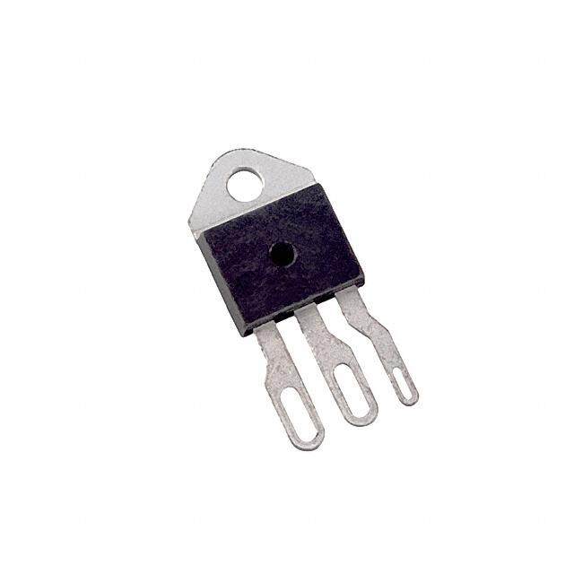
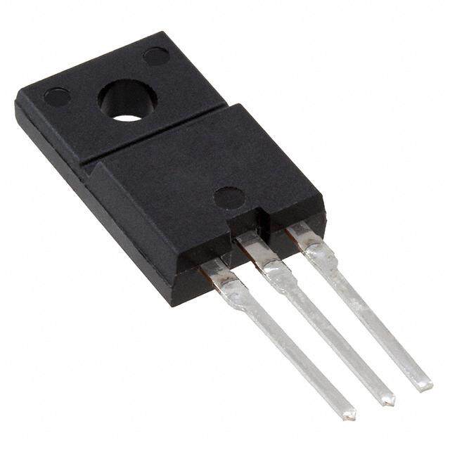
ICGOO电子元器件商城为您提供S6012R由Littelfuse设计生产,在icgoo商城现货销售,并且可以通过原厂、代理商等渠道进行代购。 S6012R价格参考。LittelfuseS6012R封装/规格:晶闸管 - SCR, SCR 600V 12A Standard Recovery Through Hole TO-220 Non-Isolated Tab。您可以下载S6012R参考资料、Datasheet数据手册功能说明书,资料中有S6012R 详细功能的应用电路图电压和使用方法及教程。
Littelfuse Inc. 是一家知名的电子元件制造商,其晶闸管产品广泛应用于电力控制和保护领域。型号为 S6012R 的晶闸管(SCR)是一种可控硅整流器,主要用于交流电源的开关与调压控制。

S6012R 常见的应用场景包括:

1. 家电控制:如电热水壶、电暖器、电磁炉等需要交流功率控制的家用电器中,S6012R用于实现负载的通断控制和功率调节。

2. 工业自动化:在工业设备中用于控制加热元件、电机启动、电炉温度控制等,适用于需要高可靠性和长寿命的工业环境。

3. 照明控制:用于调光系统,如舞台灯光、商业照明等,通过相位控制实现灯光亮度调节。

4. 电源管理:在不间断电源(UPS)、变频器、逆变器等电源设备中,作为关键的功率开关元件。

5. 电动工具与小家电:用于电动工具的速度控制或小家电的功率调节,具备较高的耐压和电流承载能力。

该器件具有高浪涌电流承受能力、可靠性强、响应速度快等优点,适用于中高功率的交流控制应用。
| 参数 | 数值 |
| 产品目录 | |
| 描述 | NON-SENSITIVE GATE 12.0A 600VSCR 12A 600V |
| 产品分类 | SCR - 单个分离式半导体 |
| GateTriggerCurrent-Igt | 20 mA |
| GateTriggerVoltage-Vgt | 1.5 V |
| 品牌 | Littelfuse Inc |
| 产品手册 | |
| 产品图片 |
|
| rohs | 符合RoHS无铅 / 符合限制有害物质指令(RoHS)规范要求 |
| 产品系列 | 晶体闸流管,SCR,Littelfuse S6012R- |
| 数据手册 | |
| 产品型号 | S6012R |
| SCR类型 | 标准恢复型 |
| 不重复通态电流 | 120 A |
| 产品种类 | SCR |
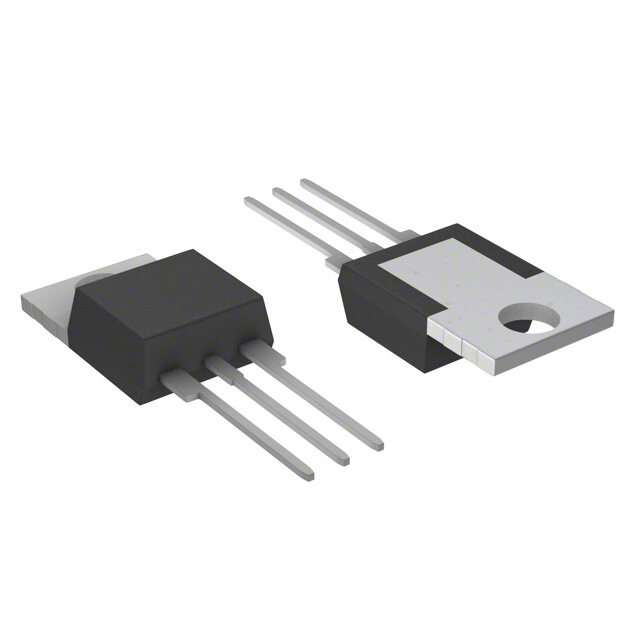
| 供应商器件封装 | TO-220(非隔离式)标片 |
| 保持电流Ih最大值 | 40 mA |
| 关闭状态漏泄电流(在VDRMIDRM下) | 0.01 mA |
| 包装 | 散装 |
| 商标 | Littelfuse |
| 安装类型 | 通孔 |
| 安装风格 | Through Hole |
| 封装 | Bulk |
| 封装/外壳 | TO-220-3 |
| 封装/箱体 | TO-220 |
| 工作温度 | -40°C ~ 125°C |
| 工厂包装数量 | 500 |
| 开启状态RMS电流-ItRMS | 12 A |
| 最大工作温度 | + 125 C |
| 最小工作温度 | - 40 C |
| 栅极触发电压-Vgt | 1.5 V |
| 栅极触发电流-Igt | 20 mA |
| 标准包装 | 500 |
| 正向电压下降 | 1.6 V |
| 电压-断态 | 600V |
| 电压-栅极触发(Vgt)(最大值) | 1.5V |
| 电压-通态(Vtm)(最大值) | 1.6V |
| 电流-不重复浪涌50、60Hz(Itsm) | 100A,120A |
| 电流-保持(Ih)(最大值) | 40mA |
| 电流-断态(最大值) | 10µA |
| 电流-栅极触发(Igt)(最大值) | 20mA |
| 电流-通态(It(AV))(最大值) | 7.6A |
| 电流-通态(It(RMS))(最大值) | 12A |
| 系列 | Sxx12x |
| 额定重复关闭状态电压VDRM | 600 V |


- 商务部:美国ITC正式对集成电路等产品启动337调查
- 曝三星4nm工艺存在良率问题 高通将骁龙8 Gen1或转产台积电
- 太阳诱电将投资9.5亿元在常州建新厂生产MLCC 预计2023年完工
- 英特尔发布欧洲新工厂建设计划 深化IDM 2.0 战略
- 台积电先进制程称霸业界 有大客户加持明年业绩稳了
- 达到5530亿美元!SIA预计今年全球半导体销售额将创下新高
- 英特尔拟将自动驾驶子公司Mobileye上市 估值或超500亿美元
- 三星加码芯片和SET,合并消费电子和移动部门,撤换高东真等 CEO
- 三星电子宣布重大人事变动 还合并消费电子和移动部门
- 海关总署:前11个月进口集成电路产品价值2.52万亿元 增长14.8%


PDF Datasheet 数据手册内容提取
Thyristors 12 Amp Standard SCRs Sxx12x Series RoHS Description This Sxx12x SCR series is ideal for uni-directional switch applications such as phase control, heating, motor speed controls, converters/rectifiers and capacitive discharge ignitions. These SCRs have a low gate current trigger level of 20 mA at approximately 1.5V. Features & Benefits • Halogen free and • Voltage capability up RoHS compliant to 1000 V • Glass – passivated • Surge capability up to 120 Agency Approval junctions A at 60 Hz half cycle • Electrically isolated Agency Agency File Number “L-Package” is UL recognized for 2500Vrms L Package: E71639 Main Features Applications Typical applications includes capacitive discharge system Symbol Value Unit for motorcycle engine CDI, portable generator engine I 12 A ignition, strobe lights and nailers, as well as generic T(RMS) rectifiers, battery voltage regulators and converters. Also VDRM/VRRM 400 to 1000 V AC control & rectification for power tools, home/brown goods, white goods appliances and 2-wheeler rectifier/ I 20 mA GT battery regulators. Internally constructed isolated packages are offered for ease of heat sinking with highest isolation voltage. Additional Information Schematic Symbol Datasheet Resources Samples A K G © 2018 Littelfuse, Inc. Specifications are subject to change without notice. Revised: 01/16/18
Thyristors 12 Amp Standard SCRs Absolute Maximum Ratings Symbol Parameter Test Conditions Value Unit Sxx12L T = 72°C C I RMS on-state current Sxx12R / Sxx12N 12 A T(RMS) Sxx12D T = 105°C Sxx12V C Sxx12L T =72°C C I Average on-state current Sxx12R 7.6 A T(AV) Sxx12D T =105°C Sxx12V C Sxx12L f = 50Hz 120 Peak non-repetitive surge current Sxx12R / Sxx12N f = 60Hz 130 I A TSM (single half cycle, TJ (initial) = 25°C) Sxx12D f = 50Hz 100 Sxx12V f = 60Hz 120 Sxx12L 70 Sxx12R / Sxx12N I2t I2t Value for fusing t = 8.3 ms A2s Sxx12D p 60 Sxx12V di/dt Critical rate of rise of on-state current f = 60Hz; T = 125°C 100 A/μs J I Peak gate current T = 125°C 2 A GM J P Average gate power dissipation T = 125°C 0.5 W G(AV) J T Storage temperature range -40 to 150 stg °C T Operating junction temperature range -40 to 125 J Note: xx = voltage Electrical Characteristics (T = 25°C, unless otherwise specified) J Symbol Test Conditions Value Unit MAX. 20 I V = 12V R = 60 Ω mA GT D L MIN. 1 V V = 12V R = 60 Ω MAX. 1.5 V GT D L 400V 350 600V 300 V = V ; gate open; T = 100°C D DRM J 800V 250 dv/dt 1000V MIN. 100 V/μs 400V 250 V = V ; gate open; T = 125°C 600V 225 D DRM J 800V 200 V V = V R = 3.3 kΩ T = 125°C MIN. 0.2 V GD D DRM L J I I = 200mA (initial) MAX. 40 mA H T t I = 2A; t = 50µs; dv/dt = 5V/µs; di/dt = 30A/µs MAX. 35 μs q T p t I = 2 x I PW = 15µs I = 20A TYP. 2 μs gt G GT T © 2018 Littelfuse, Inc. Specifications are subject to change without notice. Revised: 01/16/18
Thyristors 12 Amp Standard SCRs Static Characteristics Symbol Test Conditions Value Unit V I = 24A; t = 380 µs MAX. 1.6 V TM T p 400 – 600V 10 T = 25°C J 800 – 1000V 20 I / I V = V 400 – 800V MAX. 500 μA DRM RRM DRM RRM T = 100°C J 1000V 3000 T = 125°C 400 – 800V 1000 J Thermal Resistances Symbol Parameter Value Unit Sxx12L 3.2 Sxx12R / Sxx12N 1.5 R Junction to case (AC) °C/W θ(J-C) Sxx12V 1.6 Sxx12D 1.4 Sxx12L 50 R Junction to ambient Sxx12R 40 °C/W θ(J-A) Sxx12V 70 Note: xx = voltage Figure 1: Normalized DC Gate Trigger Current Figure 2: Normalized DC Gate Trigger Voltage vs. Junction Temperature vs. Junction Temperature 2.0 2.0 of I / I (T = 25°C)GTGTJ 11..05 of V/ V (T = 25°C)GT GTJ 11..05 Ratio 0.5 Ratio 0.5 0.0 0.0 -40 -15 10 35 60 85 100 125 -40 -15 10 35 60 85 110 125 Junction Temperature (T ) - (°C) Junction Temperature (T) - (°C) J J © 2018 Littelfuse, Inc. Specifications are subject to change without notice. Revised: 01/16/18
Thyristors 12 Amp Standard SCRs Figure 3: Normalized DC Holding Current Figure 4: On-State Current vs. On-State vs. Junction Temperature Voltage (Typical) 2.0 60 T = 25°C J 50 Ratio of I / I (T = 25°C)HHJ 011...055 Instantaneous On-state ) – AmpsCurrent (i T 234000 SSSSSxxxxxxxxxx121111R2222 /RVDL Sxx12N 10 0.0 0 -40 -15 10 35 60 85 110 125 0.6 0.7 0.8 0.9 1.0 1.1 1.2 1.3 1.4 1.5 1.6 Junction Temperature (T ) - (°C) Instantaneous On-state Voltage (v) – Volts J T Figure 5: Power Dissipation (Typical) Figure 6: Maximum Allowable Case Temperature vs. RMS On-State Current vs. RMS On-State Current 12 130 120 10 Average On-State PowerDissipation [P] - (Watts)D(AV) 468 Maximum Allowable Case Temperature (T)- °CC 1110890000 Sxx12L SSSSxxxxxxxx12111R222 /RVD Sxx12N 2 70 CURRENT WAVEFORM: Sinusoidal LOAD: Resistive or Inductive CONDUCTION ANGLE: 180° 60 0 0 2 4 6 8 10 12 14 0 2 4 6 8 10 12 RMS On-State Current [I ] - Amps RMS On-State Current [I )] - (Amps) T(RMS) T(RMS Figure 7: Maximum Allowable Case Temperature Figure 8: Maximum Allowable Ambient Temperature vs. Average On-State Current vs. RMS On-State Current 130 120 CURRENT WAVEFORM: Sinusoidal 120 ent 100 LCFOROEANEDD A:U RIRCe TsRiIsAOtTNivIN eA GNorG ILnEd:u 1c8ti0v°e mum Allowable Case mperature (T) - °CC 11109000 Sxx12L SSSSxxxxxxxx12111R222 /RVD Sxx12N ximum Allowable Ambi) - °CTemperature (TA 468000 Sxx12V Sxx12L Sxx12R axiTe 80 Ma M 20 70 CLOUARDR:E RNeTs WistAivVeE oFOr IRnMdu: cStiinvuesoidal CONDUCTION ANGLE: 180° 0 60 0.0 0.5 1.0 1.5 2.0 2.5 3.0 3.5 0 1 2 3 4 5 6 7 8 RMS On-State Current [I ] - Amps Average On-State Current [I ] - Amps T(RMS) T(AVE) Note: xx = voltage © 2018 Littelfuse, Inc. Specifications are subject to change without notice. Revised: 01/16/18
Thyristors 12 Amp Standard SCRs Figure 9: Maximum Allowable Ambient Temperature Figure 10: Peak Capacitor Discharge Current vs. Average On-State Current 1000 120 CURRENT WAVEFORM: Sinusoidal s m Allowable Ambient perature (T) - °CA 1068000 Sxx12V Sxx12L LCFOROEANEDD A:U RSIRCex TsxRiI1sAO2tTNiRvIN eA GNorG ILnEd:u 1c8ti0v°e harge Current (I) - AmpTM100 aximuTem 40 ak Disc ITRM M 20 Pe tW 0 1005. 5.0 25.0 50.0 0.0 0.5 1.0 1.5 2.0 Pulse Current Duration (t ) - ms w Average On-State Current [I ] - Amps T(AVE) Figure 11: Peak Capacitor Discharge Current Derating 1.2 1.0 nt e urr0.8 C k a e P0.6 d e z ali m0.4 or N 0.2 0.0 0 25 50 75 100 125 150 Case Temperature (T) - °C C Figure 12: Surge Peak On-State Current vs. Number of Cycles 1000 SUPPLY FREQUENCY: 60 Hz Sinusoidal LOAD: Resistive RMS On-State Current: [I ]: Maximum Rated s T(RMS) ve)mp Value at Specified Case Temperature Peak Surge (Non-repetitin-state Current (I ) – ATSM 10100 N12..o Gf Otrtoeaeavtlmsleteo:edprw l ecoviornaaandgltut umrserou.ealr ymgh eana soyc t urb erberteue l nrornetse ptind edt aetuotrrev insdatg le.u aanndtidyl - jsiumtnamctetei o dnia tely O 1 1 10 100 1000 Surge Current Duration - Full Cycles © 2018 Littelfuse, Inc. Specifications are subject to change without notice. Revised: 01/16/18
Thyristors 12 Amp Standard SCRs Soldering Parameters Reflow Condition Pb – Free assembly t P T P - Temperature Min (Ts(min)) 150°C e RRaammpp--uupp Pre Heat -- TTeimmep e(mraitnu rteo Mmaaxx )( T(ts()max)) 2600 0–° C180 secs rutare TS(mTaxL) tL s p m RRaammpp--ddoown Average ramp up rate (Liquidus Temp) PPrreehheeaatt (TL) to peak 5°C/second max eT TS(min) t T to T - Ramp-up Rate 5°C/second max S S(max) L - Temperature (T) (Liquidus) 217°C Reflow L 25 - Temperature (tL) 60 – 150 seconds time to peak temperature Time Peak Temperature (T) 260+0/-5 °C P Time within 5°C of actual peak 20 – 40 seconds Temperature (t) p Ramp-down Rate 5°C/second max Time 25°C to peak Temperature (T) 8 minutes Max. P Do not exceed 280°C Physical Specifications Environmental Specifications Test Specifications and Conditions Terminal Finish 100% Matte Tin-plated MIL-STD-750, M-1040, Cond A Applied AC Blocking Peak AC voltage @ 125°C for 1008 hours UL recognized epoxy meeting flammability Body Material MIL-STD-750, M-1051, rating 94V-0 Temperature Cycling 100 cycles; -40°C to +150°C; 15-min dwell-time Lead Material Copper Alloy EIA / JEDEC, JESD22-A101 Temperature/ 1008 hours; 320V - DC: 85°C; 85% Humidity rel humidity MIL-STD-750, M-1031, Design Considerations High Temp Storage 1008 hours; 150°C Careful selection of the correct component for the Low-Temp Storage 1008 hours; -40°C application’s operating parameters and environment will Resistance to go a long way toward extending the operating life of the MIL-STD-750 Method 2031 Solder Heat Thyristor. Good design practice should limit the maximum Solderability ANSI/J-STD-002, category 3, Test A continuous current through the main terminals to 75% of the component rating. Other ways to ensure long life for Lead Bend MIL-STD-750, M-2036 Cond E a power discrete semiconductor are proper heat sinking and selection of voltage ratings for worst case conditions. Overheating, overvoltage (including dv/dt), and surge currents are the main killers of semiconductors. Correct mounting, soldering, and forming of the leads also help protect against component damage. © 2018 Littelfuse, Inc. Specifications are subject to change without notice. Revised: 01/16/18
Thyristors 12 Amp Standard SCRs Dimensions — TO-220AB (L-Package) — Isolated Mounting Tab TC MEASURING POINT AREA (REF.) 0.17 IN2 Inches Millimeters O Dimension E A P .83.2130 Min Max Min Max A 0.380 0.420 9.65 10.67 B C B 0.105 0.115 2.67 2.92 13.36 D .526 C 0.230 0.250 5.84 6.35 7.01 .276 D 0.590 0.620 14.99 15.75 E 0.142 0.147 3.61 3.73 F F 0.110 0.130 2.79 3.30 G 0.540 0.575 13.72 14.61 R G H 0.025 0.035 0.64 0.89 L H J 0.195 0.205 4.95 5.21 K 0.095 0.105 2.41 2.67 CATHODE ANODE GATE N K L 0.060 0.075 1.52 1.91 J M M 0.085 0.095 2.16 2.41 N 0.018 0.024 0.46 0.61 O 0.178 0.188 4.52 4.78 P 0.045 0.060 1.14 1.52 R 0.038 0.048 0.97 1.22 Dimensions — TO-220AB (R-Package) — Non-Isolated Mounting Tab Common with Center Lead TC MEASURING POINT AREA (REF.) 0.17 IN2 Inches Millimeters O Dimension E A P .83.2130 Min Max Min Max ANODE A 0.380 0.420 9.65 10.67 B C B 0.105 0.115 2.67 2.92 13.36 D .526 C 0.230 0.250 5.84 6.35 .72.0716 D 0.590 0.620 14.99 15.75 E 0.142 0.147 3.61 3.73 F NOTCH IN F 0.110 0.130 2.79 3.30 GATE LEAD TO ID. G 0.540 0.575 13.72 14.61 NON-ISOLATED R TAB G H 0.025 0.035 0.64 0.89 L J 0.195 0.205 4.95 5.21 H K 0.095 0.105 2.41 2.67 CATHODE ANODE GATE K N L 0.060 0.075 1.52 1.91 J M Note: Maximum torque to be applied to mounting tab M 0.085 0.095 2.16 2.41 is 8 in-lbs. (0.904 Nm). N 0.018 0.024 0.46 0.61 O 0.178 0.188 4.52 4.78 P 0.045 0.060 1.14 1.52 R 0.038 0.048 0.97 1.22 © 2018 Littelfuse, Inc. Specifications are subject to change without notice. Revised: 01/16/18
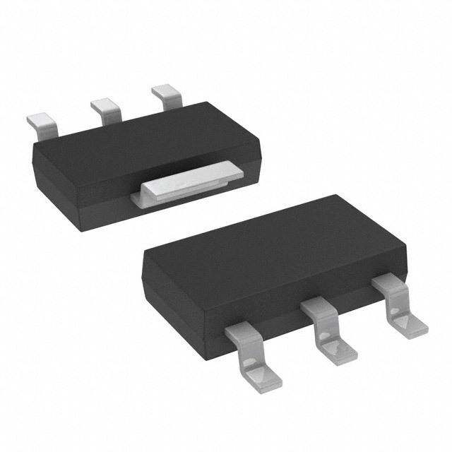
Thyristors 12 Amp Standard SCRs Dimensions — TO-251AA (V/I-Package) — V/I-PAK Through Hole TC MEASURING POINT AREA: 0.040 IN2 Inches Millimeters Dimension Anode E H 5.28 Min Typ Max Min Typ Max D J .208 A 0.040 0.044 0.050 1.02 1.11 1.27 B 0.235 0.242 0.245 5.97 6.15 6.22 A 5.34 C 0.350 0.361 0.375 8.89 9.18 9.53 .210 D 0.205 0.208 0.213 5.21 5.29 5.41 B E 0.255 0.262 0.265 6.48 6.66 6.73 P R F 0.027 0.031 0.033 0.69 0.80 0.84 S Q G 0.087 0.090 0.093 2.21 2.28 2.36 K H 0.085 0.092 0.095 2.16 2.34 2.41 C I 0.176 0.180 0.184 4.47 4.57 4.67 J 0.018 0.020 0.023 0.46 0.51 0.58 K 0.038 0.040 0.044 0.97 1.01 1.12 Cathode L F L 0.018 0.020 0.023 0.46 0.52 0.58 Anode G GATE P 0.042 0.047 0.052 1.06 1.20 1.32 I Q 0.034 0.039 0.044 0.86 1.00 1.11 R 0.034 0.039 0.044 0.86 1.00 1.11 S 0.074 0.079 0.084 1.86 2.00 2.11 Dimensions — TO-252AA (D-Package) — D-PAK Surface Mount Anode DE TC MEASURING POINT .52.0288 .62.6741 Dimension Inches Millimeters Min Typ Max Min Typ Max A 5.34 6.71 A 0.040 0.043 0.050 1.02 1.09 1.27 .210 .264 B B 0.235 0.243 0.245 5.97 6.16 6.22 1.60 C 0.106 0.108 0.113 2.69 2.74 2.87 P .063 C Q 1.80 D 0.205 0.208 0.213 5.21 5.29 5.41 GATE .071 Cathode F AREA: 0.040 IN2 E 0.255 0.262 0.265 6.48 6.65 6.73 Anode G .1138 .41.8610 F 0.027 0.031 0.033 0.69 0.80 0.84 I G 0.087 0.090 0.093 2.21 2.28 2.36 O L K J H H 0.085 0.092 0.095 2.16 2.33 2.41 M I 0.176 0.179 0.184 4.47 4.55 4.67 N J 0.018 0.020 0.023 0.46 0.51 0.58 K 0.038 0.040 0.044 0.97 1.02 1.12 L 0.018 0.020 0.023 0.46 0.51 0.58 M 0.000 0.000 0.004 0.00 0.00 0.10 N 0.021 0.026 0.027 0.53 0.67 0.69 O 0° 0° 5° 0° 0° 5° P 0.042 0.047 0.052 1.06 1.20 1.32 Q 0.034 0.039 0.044 0.86 1.00 1.11 © 2018 Littelfuse, Inc. Specifications are subject to change without notice. Revised: 01/16/18
Thyristors 12 Amp Standard SCRs Dimensions — TO-263 (N-Package) — D2PAK Surface Mount Inches Millimeters Dimension Min Max Min Max A 0.360 0.370 9.14 9.40 B 0.380 0.420 9.65 10.67 C 0.178 0.188 4.52 4.78 D 0.025 0.035 0.64 0.89 E 0.045 0.060 1.14 1.52 F 0.060 0.075 1.52 1.91 G 0.095 0.105 2.41 2.67 H 0.092 0.102 2.34 2.59 J 0.018 0.024 0.46 0.61 K 0.090 0.110 2.29 2.79 S 0.590 0.625 14.99 15.88 V 0.035 0.045 0.89 1.14 U 0.002 0.010 0.05 0.25 W 0.040 0.070 1.02 1.78 Product Selector Voltage Part Number Gate Sensitivity Type Package 400V 600V 800V 1000V Sxx12L X X X X 20mA Sensitive SCR TO-220L Sxx12R X X X X 20mA Sensitive SCR TO-220R Sxx12V X X X X 20mA Standard SCR TO-251 Sxx12D X X X X 20mA Standard SCR TO-252 Sxx12N X X X X 20mA Standard SCR TO-263 Note: xx = voltage/10 Packing Options Part Number Marking Weight Packing Mode Base Quantity Sxx12LTP Sxx12L 2.2 g Tube 500 (50 per tube) Sxx12RTP Sxx12R 2.2 g Tube 500 (50 per tube) Sxx12DTP Sxx12D 0.3 g Tube 750 (75 per tube) Sxx12DRP Sxx12D 0.3 g Embossed Carrier 2500 Sxx12VTP Sxx12V 0.4 g Tube 750 (75 per tube) Sxx12NRP Sxx12N 1.6g Embossed Carrier 2500 Sxx12NTP Sxx12N 1.6 g Tube 750 (75 per tube) Note: xx = Voltage/10 © 2018 Littelfuse, Inc. Specifications are subject to change without notice. Revised: 01/16/18
Thyristors 12 Amp Standard SCRs TO-252 Embossed Carrier Reel Pack (RP) Specifications Part Marking System Meets all EIA-481-2 Standards TO-251AA - (V Package ) TO-252AA - (D Package) S6012D S6012D 0(.41.507) 0(1..055)9 DIA Gate Cathode YMLDD YMLDD ® ® (016.6.03) (01.35.234)* XXXXXX XXDC XXXXXX XXDC XXXXXX XXDC XXXXXX D YMLa:: t:YLe Meo Cacoraon tCdtiohoen d CM eCooaddrekeing DD: Calendar Code TO-263AA (N Package) * Cover tape 0(8.3.01)5 Anode TO-220 AB - (L Package ) TO-220 AB - (R Package) 12.99 0.512 (13.0) (330.0) ArbDoiarm Heotleer Da(arinemd ien mn isniilcolihmnesesters). SY6M012L SY6M012R ® ® 0.64 (16.3) Date Code Marking Y:Year Code M: Month Code Direction of Feed XXX: Lot Trace Code Part Numbering System S 60 12 R 56 COMDPEOVNICEEN TT TYYPPEE LEAD FORM DIMENSIONS S: SCR xx: Lead Form Option VOLTAGE RATING 40: 400V SENSITIVITY & TYPE 60: 600V (blank): 20mA 80: 800V K0: 1000V CURRENT RATING LP:A TCOK-A22G0E I sToYlPatEed 12: 12A R: TO-220 Non-Isolated V: TO-251 (V/I-Pak) D: TO-252 (D-Pak) N: TO-263 (D2PAK) © 2018 Littelfuse, Inc. Specifications are subject to change without notice. Revised: 01/16/18