 Datasheet下载
- 型号: S8065JTP
- 制造商: Littelfuse
- 库位|库存: xxxx|xxxx
- 要求:
| 数量阶梯 | 香港交货 | 国内含税 |
| +xxxx | $xxxx | ¥xxxx |
查看当月历史价格
查看今年历史价格
S8065JTP产品简介:
ICGOO电子元器件商城为您提供S8065JTP由Littelfuse设计生产,在icgoo商城现货销售,并且可以通过原厂、代理商等渠道进行代购。 S8065JTP价格参考。LittelfuseS8065JTP封装/规格:晶闸管 - SCR, SCR 800V 65A Standard Recovery Through Hole TO-218X Isolated。您可以下载S8065JTP参考资料、Datasheet数据手册功能说明书,资料中有S8065JTP 详细功能的应用电路图电压和使用方法及教程。
Littelfuse Inc. 的 S8065JTP 是一款硅控整流器(SCR),属于晶闸管的一种,广泛应用于交流电源控制场合。该器件具有高电压和电流承受能力,适用于需要可靠开关和功率控制的中高功率系统。

典型应用场景包括:家用及工业电加热控制,如电暖器、热水器、烤箱等温度调节系统;照明调光电路,特别是白炽灯或卤素灯的相位控制调光;电机速度控制,如风扇、小型电动工具中的交流电机调速;以及各类电源开关和过压保护电路。

S8065JTP 采用TO-220封装,具备良好的散热性能和电气隔离能力,适合印刷电路板安装,常用于固态继电器(SSR)、电源控制器和自动控制系统中。其触发灵敏度高,可在较小的门极电流下可靠导通,提高了系统的响应速度与稳定性。

由于其耐高温、抗浪涌能力强,S8065JTP 还适用于电网波动较大或工作环境较恶劣的场合,如工业自动化设备、电源管理模块和电力调节装置等。总体而言,该SCR在需要精确控制交流负载的电子设备中发挥着关键作用,兼具可靠性与成本效益。
| 参数 | 数值 |
| 产品目录 | |
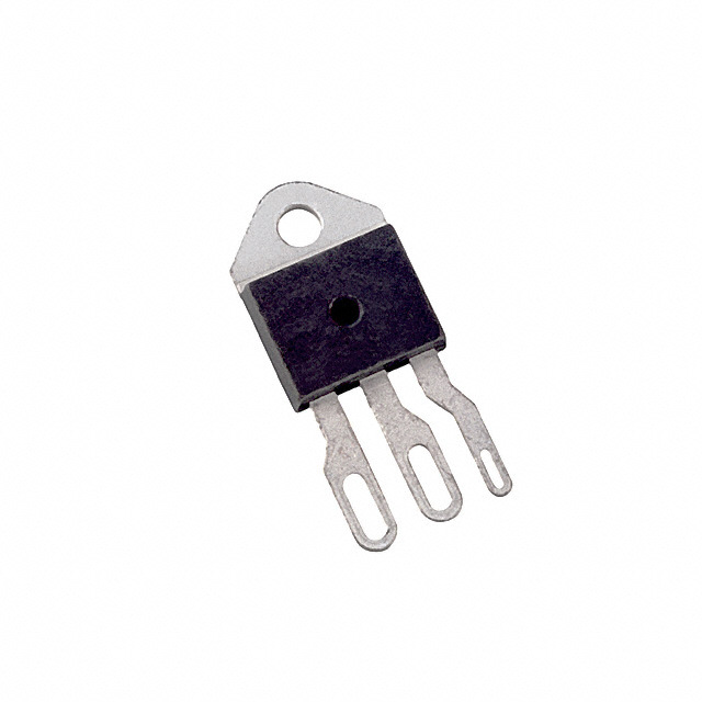
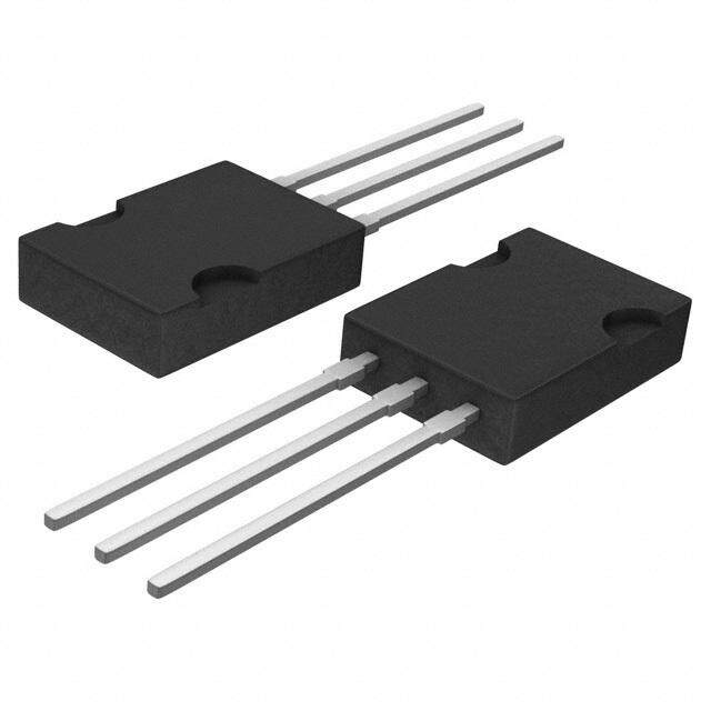
| 描述 | SCR NON-SENS 800V 65A ISO TO218XSCR SCR 800V 65A Iso |
| 产品分类 | SCR - 单个分离式半导体 |
| GateTriggerCurrent-Igt | 50 mA |
| GateTriggerVoltage-Vgt | 2 V |
| 品牌 | Littelfuse Inc |
| 产品手册 | |
| 产品图片 |
|
| rohs | 符合RoHS无铅 / 符合限制有害物质指令(RoHS)规范要求 |
| 产品系列 | 晶体闸流管,SCR,Littelfuse S8065JTP- |
| 数据手册 | |
| 产品型号 | S8065JTP |
| SCR类型 | 标准恢复型 |
| 不重复通态电流 | 950 A |
| 产品种类 | SCR |
| 供应商器件封装 | TO-218X 隔离式 |
| 保持电流Ih最大值 | 80 mA |
| 关闭状态漏泄电流(在VDRMIDRM下) | 0.02 mA |
| 其它名称 | S8065J |
| 包装 | 管件 |
| 商标 | Littelfuse |
| 安装类型 | 通孔 |
| 安装风格 | Through Hole |
| 封装 | Tube |
| 封装/外壳 | TO-218X-3(隔离式) |
| 封装/箱体 | TO-218 |
| 工作温度 | -40°C ~ 125°C |
| 工厂包装数量 | 250 |
| 开启状态RMS电流-ItRMS | 65 A |
| 最大工作温度 | + 125 C |
| 最小工作温度 | - 40 C |
| 栅极触发电压-Vgt | 2 V |
| 栅极触发电流-Igt | 50 mA |
| 标准包装 | 25 |
| 正向电压下降 | 1.8 V |
| 电压-断态 | 800V |
| 电压-栅极触发(Vgt)(最大值) | 2V |
| 电压-通态(Vtm)(最大值) | 1.8V |
| 电流-不重复浪涌50、60Hz(Itsm) | 800A,950A |
| 电流-保持(Ih)(最大值) | 80mA |
| 电流-断态(最大值) | 20µA |
| 电流-栅极触发(Igt)(最大值) | 50mA |
| 电流-通态(It(AV))(最大值) | 41A |
| 电流-通态(It(RMS))(最大值) | 65A |
| 系列 | Sxx65x |
| 额定重复关闭状态电压VDRM | 800 V |


- 商务部:美国ITC正式对集成电路等产品启动337调查
- 曝三星4nm工艺存在良率问题 高通将骁龙8 Gen1或转产台积电
- 太阳诱电将投资9.5亿元在常州建新厂生产MLCC 预计2023年完工
- 英特尔发布欧洲新工厂建设计划 深化IDM 2.0 战略
- 台积电先进制程称霸业界 有大客户加持明年业绩稳了
- 达到5530亿美元!SIA预计今年全球半导体销售额将创下新高
- 英特尔拟将自动驾驶子公司Mobileye上市 估值或超500亿美元
- 三星加码芯片和SET,合并消费电子和移动部门,撤换高东真等 CEO
- 三星电子宣布重大人事变动 还合并消费电子和移动部门
- 海关总署:前11个月进口集成电路产品价值2.52万亿元 增长14.8%


PDF Datasheet 数据手册内容提取
Teccor® brand Thyristors 65 / 70 Amp Standard SCRs Sxx65x & Sxx70x Series ® Description Excellent unidirectional switches for phase control applications such as heating and motor speed controls. Standard phase control SCRs are triggered with few milliamperes of current at less than 1.5V potential. Features & Benefits (cid:116)(cid:1)(cid:1)(cid:51)(cid:80)(cid:41)(cid:52)(cid:1)(cid:68)(cid:80)(cid:78)(cid:81)(cid:77)(cid:74)(cid:66)(cid:79)(cid:85) (cid:116)(cid:1)(cid:1)(cid:55)(cid:80)(cid:77)(cid:85)(cid:66)(cid:72)(cid:70)(cid:1)(cid:68)(cid:66)(cid:81)(cid:66)(cid:67)(cid:74)(cid:77)(cid:74)(cid:85)(cid:90)(cid:1)(cid:86)(cid:81)(cid:1) to 1000 V (cid:116)(cid:1)(cid:1)(cid:40)(cid:77)(cid:66)(cid:84)(cid:84)(cid:1)(cid:111)(cid:1)(cid:81)(cid:66)(cid:84)(cid:84)(cid:74)(cid:87)(cid:66)(cid:85)(cid:70)(cid:69)(cid:1) junctions (cid:116)(cid:1)(cid:1)(cid:52)(cid:86)(cid:83)(cid:72)(cid:70)(cid:1)(cid:68)(cid:66)(cid:81)(cid:66)(cid:67)(cid:74)(cid:77)(cid:74)(cid:85)(cid:90)(cid:1)(cid:86)(cid:81)(cid:1)(cid:85)(cid:80)(cid:1) 950 A Applications Agency Approval Typical applications are AC solid-state switches, industrial Agency Agency File Number power tools, exercise equipment, white goods and commercial appliances. J & K Packages: E71639 ® Internally constructed isolated packages are offered for ease of heat sinking with highest isolation voltage. Main Features s Schematic Symbol R C Symbol Value Unit S I 65 & 70 A A T(RMS) VDRM/VRRM 400 to 1000 V A K 70 / I 50 mA 5 GT 6 G Absolute Maximum Ratings Symbol Parameter Test Conditions Value Unit Sxx65J T = 75°C 65 I RMS on-state current Sxx65K C A T(RMS) Sxx70W T = 80°C 70 C Sxx65J TC = 75°C 41.0 A I Average on-state current Sxx65K T(AV) Sxx70W T = 80°C 45.0 A C single half cycle; f = 50Hz; 800 T (initial) = 25°C I Peak non-repetitive surge current J A TSM single half cycle; f = 60Hz; 950 T (initial) = 25°C J I2t I2t Value for fusing t = 8.3 ms 3745 A2s p di/dt Critical rate of rise of on-state current f = 60Hz ; T= 125°C 200 A/μs J T= 125°C I Peak gate current J 5.0 A GM P = μS W P Average gate power dissipation T= 125°C 1.0 W G(AV) J T Storage temperature range -40 to 150 °C stg T Operating junction temperature range -40 to 125 °C J ©2010 Littelfuse, Inc 305 Sxx65x & Sxx70x Series Specifications are subject to change without notice. Please refer to http://www.littelfuse.com for current information. Revised: May 10, 2010 09:33 PM
Teccor® brand Thyristors 65 / 70 Amp Standard SCRs Electrical Characteristics (T = 25°C, unless otherwise specified) J Symbol Test Conditions Value Unit MAX. 50 I mA GT V = 12V; R = 30 (cid:56) MIN. 5 D L V MAX. 2.0 V GT 400V 650 600V 600 V = V ; gate open; T = 100°C D DRM J 800V 500 dv/dt 1000V MIN. 250 V/μs 400V 550 V = V ; gate open; T = 125°C 600V 500 D DRM J 800V 475 V V = V ; R = 3.3 k(cid:56); T = 125°C MIN. 0.2 V GD D DRM L J I I = 400mA (initial) MAX. 80 mA H T t (1) MAX. 35 μs q t I = 2 x I ; PW = 15μs; I = 140A TYP. 2.5 μs gt G GT T Note : (1) I=2A; t=50μs; dv/dt=5V/μs; di/dt=-30A/μs T p Static Characteristics Symbol Test Conditions Value Unit 65A Device I = 130A; t = 380μs V T p MAX. 1.8 V TM 70A Device I = 140A; t = 380μs T p 400 – 800V 20 T = 25°C J 1000 V 30 400 – 600V 1500 I / I V / V T = 100°C 800V MAX. 2000 μA DRM RRM DRM RRM J 1000V 5000 400V – 600V 3000 T = 125°C J 800V 5000 Thermal Resistances Symbol Parameter Value Unit Sxx65J 0.86 R Junction to case (AC) Sxx65K °C/W (cid:82)(J-C) Sxx70W 0.6 Note: xx = voltage Sxx65x & Sxx70x Series 306 ©2010 Littelfuse, Inc Specifications are subject to change without notice. Revised: May 10, 2010 09:33 PM Please refer to http://www.littelfuse.com for current information.
Teccor® brand Thyristors 65 / 70 Amp Standard SCRs Figure 1: Normalized DC Gate Trigger Current Figure 2: Normalized DC Gate Trigger Voltage vs. Junction Temperature vs. Junction Temperature 2.0 2.0 Ratio of I /I (T = 25°C)GTGTJ011...055 Ratio of V /V (T=25°C)GTGTJ 011...055 0.0 0.0 -40 -15 10 35 60 85 110 125 -40 -15 10 35 60 85 110 125 Junction Temperature (T) -- (°C) Junction Temperature (T) -- (°C) J J Figure 3: Normalized DC Holding Current Figure 4: On-State Current vs. On-State vs. Junction Temperature Voltage (Typical) 2.0 200 mps 180 TJ = 25°C A of I /I (T =25°C)HHJ11..05 On-state Current (i) – T11118024600000 70 A SCRs Ratio 0.5 aneous 4600 65/ nt sta 20 n 0.0 I 0 -40 -15 10 35 60 85 110 125 0.7 0.8 0.9 1.0 1.1 1.2 1.3 1.4 1.5 1.6 Junction Temperature (T) -- (°C) Instantaneous On-state Voltage (v) – Volts J T Figure 5: Power Dissipation (Typical) Figure 6: Maximum Allowable Case Temperature vs. RMS On-State Current vs. RMS On-State Current 60 130 ower Dissipation W atts) 4500 Case Temperature C 111110221150505 rmTfmtsoeeohmerecle donnh pem"tdiseKgre. mrh"mda p etsfeuanuolrctdrreikg ne> aedgd5g e 0cetfpoeAo ermnr anr d>mtpdii5nteisSi0ngro Aaxgc nwtxo uor7unimrnt0stehi Wesnl. e i "uctoaJsoond "nnul yoltasei r rnan cr"nuougWdowrthr u"ne lspcnoe aactat nucdurk ersserac exeigos cnsem etiisn ner- tcaedeerq nPe uld CeieraBedd - On-State P[P] - (D (AV)2300 Allowable (T)-°C1909500 SSxxxx6655KJ e m Averag 10 aximu 8850 CULRORAEND:T R WeAsiVstEiFvOe RoMr I:n Sdiuncutsivoeidal M 75 CONDUCTION ANGLE: 180° 0 70 0 10 20 30 40 50 60 70 0 10 20 30 40 50 60 70 80 RMS On-State Current [IT(R MS)] - (Am ps) RMS On-State Current [IT(RMS)] - Amps Note: xx = voltage ©2010 Littelfuse, Inc 307 Sxx65x & Sxx70x Series Specifications are subject to change without notice. Please refer to http://www.littelfuse.com for current information. Revised: May 10, 2010 09:33 PM
Teccor® brand Thyristors 65 / 70 Amp Standard SCRs Figure 7: Maximum Allowable Case Temperature vs. Average On-State Current 130 The "K" package rating with its narrow leads is e 125 intended for high surge condition use only and not ur recommended for >32A (AV) continuous current use at 120 since lead temperature depending on lead length can mper 115 epxaccekaegde PsC aBr es oreldceorm mmeeltnindge dte fmorp >e3r2aAtu r(Ae.V ")J c"o onrt i"nWu"- e Te 110 ous current requirements. able CasT) - °CC110050 Sxx70W ow( 95 Sxx65K All 90 Sxx65J m u 85 m axi 80 CURRENT WAVEFORM: Sinusoidal M 75 LOAD: Resistive or Inductive CONDUCTION ANGLE: 180° 70 0 5 10 15 20 25 30 35 40 45 50 Average On-State Current [I ] - Amps T(AVE) Figure 8: Peak Capacitor Discharge Current Figure 9: Peak Capacitor Discharge Current Derating 10000 1.2 s mp 1.0 nt (I) - ATM k Current 0.8 Curre 1000 d Pea 0.6 harge malize 0.4 sc or k Di ITRM N a 0.2 e P tW 100 0.0 0.5 1.0 10.0 50.0 0 25 50 75 100 125 150 Pulse Current Duration (tw) - ms Case Temperature (TC) - °C Figure 10: Surge Peak On-State Current vs. Number of Cycles 1000 SUPPLY FREQUENCY: 60 Hz Sinusoidal LOAD: Resistive RMS On-State Current: [I ]: Maximum Rated T(RMS) Value at Specified Case Temperature s Sxx70W ve)mp ak Surge (Non-repetitistate Current (I) – ATSM 100 SSxxxx6655KJ N12..o Gf Otrtoeaeavtlmsleteo:edprw l ecoviornaaandgltut umrserou.ealr ymgh eana soyc t urb erberteeu l nrornets eptind edt aetuotrrev insdatg le.u aanndtidyl - jsiumtnamctetei o dnia tely PeOn- 10 1 10 100 1000 Surge Current Duration -- Full Cycles Note: xx = Voltage Sxx65x & Sxx70x Series 308 ©2010 Littelfuse, Inc Specifications are subject to change without notice. Revised: May 10, 2010 09:33 PM Please refer to http://www.littelfuse.com for current information.
Teccor® brand Thyristors 65 / 70 Amp Standard SCRs Soldering Parameters Reflow Condition Pb – Free assembly t P T P - Temperature Min (T ) 150°C RRaammpp--uupp s(min) e r T Pre Heat - Temperature Max (Ts(max)) 200°C uta T L tL - Time (min to max) (t) 60 – 180 secs re S(max) s p RRaammpp--ddoown Average ramp up rate (Liquidus Temp) m PPrreehheeaatt (T) to peak 5°C/second max eT T L S(min) t T to T - Ramp-up Rate 5°C/second max S S(max) L - Temperature (T) (Liquidus) 217°C Reflow L 25 - Temperature (t) 60 – 150 seconds time to peak temperature Time L Peak Temperature (T) 260+0/-5 °C P Time within 5°C of actual peak 20 – 40 seconds Temperature (t) p Ramp-down Rate 5°C/second max Time 25°C to peak Temperature (T) 8 minutes Max. P Do not exceed 280°C Physical Specifications Environmental Specifications Test Specifications and Conditions s Terminal Finish 100% Matte Tin-plated R MIL-STD-750, M-1040, Cond A Applied C AC Blocking Peak AC voltage @ 125°C for 1008 hours S UL recognized epoxy meeting flammability Body MIL-STD-750, M-1051, A classification 94V-0 Temperature Cycling 100 cycles; -40°C to +150°C; 0 15-min dwell-time 7 Lead Material Copper Alloy EIA / JEDEC, JESD22-A101 5/ Temperature/ 6 1008 hours; 320V - DC: 85°C; Humidity 85% rel humidity MIL-STD-750, M-1031, Design Considerations High Temp Storage 1008 hours; 150°C Careful selection of the correct device for the application’s Low-Temp Storage 1008 hours; -40°C operating parameters and environment will go a long way MIL-STD-750, M-1056 toward extending the operating life of the Thyristor. Good 10 cycles; 0°C to 100°C; 5-min dwelltime Thermal Shock design practice should limit the maximum continuous at each temperature; 10 sec (max) transfer current through the main terminals to 75% of the device time between temperature rating. Other ways to ensure long life for a power discrete EIA / JEDEC, JESD22-A102 semiconductor are proper heat sinking and selection of Autoclave 168 hours (121°C at 2 ATMs) and voltage ratings for worst case conditions. Overheating, 100% R/H overvoltage (including dv/dt), and surge currents are Resistance to MIL-STD-750 Method 2031 the main killers of semiconductors. Correct mounting, Solder Heat soldering, and forming of the leads also help protect Solderability ANSI/J-STD-002, category 3, Test A against component damage. Lead Bend MIL-STD-750, M-2036 Cond E ©2010 Littelfuse, Inc 309 Sxx65x & Sxx70x Series Specifications are subject to change without notice. Please refer to http://www.littelfuse.com for current information. Revised: May 10, 2010 09:33 PM
Teccor® brand Thyristors 65 / 70 Amp Standard SCRs Dimensions – TO-218X (W Package) — Non-Isolated Mounting Tab Inches Millimeters C Dimension ANODE B D Min Max Min Max U (diameter) A 0.810 0.835 20.57 21.21 B 0.610 0.630 15.49 16.00 Tc Measurement C 0.178 0.188 4.52 4.78 Point A D 0.055 0.070 1.40 1.78 E Z F E 0.487 0.497 12.37 12.62 F 0.635 0.655 16.13 16.64 G 0.022 0.029 0.56 0.74 CATHODE H 0.075 0.095 1.91 2.41 W X J 0.575 0.625 14.61 15.88 J K 0.256 0.264 6.50 6.71 GATE N L 0.220 0.228 5.58 5.79 R M 0.080 0.088 2.03 2.24 T S M P G N 0.169 0.177 4.29 4.49 Y ANODE H P 0.034 0.042 0.86 1.07 K L R 0.113 0.121 2.87 3.07 V Note: Maximum torque to S 0.086 0.096 2.18 2.44 be applied to mounting tab is 8 in-lbs. (0.904 Nm). T 0.156 0.166 3.96 4.22 U 0.164 0.165 4.10 4.20 V 0.603 0.618 15.31 15.70 W 0.000 0.005 0.00 0.13 X 0.003 0.012 0.07 0.30 Y 0.028 0.032 0.71 0.81 Z 0.085 0.095 2.17 2.42 Dimensions – TO-218AC (K Package) — Isolated Mounting Tab Tc Measurement Point Inches Millimeters U (diameter) C Dimension B Min Max Min Max D A 0.810 0.835 20.57 21.21 B 0.610 0.630 15.49 16.00 A C 0.178 0.188 4.52 4.78 F E D 0.055 0.070 1.40 1.78 W E 0.487 0.497 12.37 12.62 F 0.635 0.655 16.13 16.64 GATE P J G 0.022 0.029 0.56 0.74 CATHODE H 0.075 0.095 1.91 2.41 ANODE M H J 0.575 0.625 14.61 15.88 Q G K 0.211 0.219 5.36 5.56 R N L 0.422 0.437 10.72 11.10 K Note: Maximum torque M 0.058 0.068 1.47 1.73 to be applied to mounting L tab is 8 in-lbs. (0.904 Nm). N 0.045 0.055 1.14 1.40 P 0.095 0.115 2.41 2.92 Q 0.008 0.016 0.20 0.41 R 0.008 0.016 0.20 0.41 U 0.164 0.165 4.10 4.20 W 0.085 0.095 2.17 2.42 Sxx65x & Sxx70x Series 310 ©2010 Littelfuse, Inc Specifications are subject to change without notice. Revised: May 10, 2010 09:33 PM Please refer to http://www.littelfuse.com for current information.
Teccor® brand Thyristors 65 / 70 Amp Standard SCRs Dimensions – TO-218X (J Package) — Isolated Mounting Tab Common with Center Lead C Inches Millimeters Dimension B D Min Max Min Max U (diameter) A 0.810 0.835 20.57 21.21 Tc B 0.610 0.630 15.49 16.00 Measurement C 0.178 0.188 4.52 4.78 Point A D 0.055 0.070 1.40 1.78 F E Z E 0.487 0.497 12.37 12.62 F 0.635 0.655 16.13 16.64 G 0.022 0.029 0.56 0.74 CATHODE H 0.075 0.095 1.91 2.41 W X J 0.575 0.625 14.61 15.88 J GATE K 0.256 0.264 6.50 6.71 N R L 0.220 0.228 5.58 5.79 T S M 0.080 0.088 2.03 2.24 M P G N 0.169 0.177 4.29 4.49 Y ANODE H P 0.034 0.042 0.86 1.07 K L R 0.113 0.121 2.87 3.07 V Note: Maximum torque to be applied to mounting tab S 0.086 0.096 2.18 2.44 is 8 in-lbs. (0.904 Nm). T 0.156 0.166 3.96 4.22 U 0.164 0.165 4.10 4.20 V 0.603 0.618 15.31 15.70 W 0.000 0.005 0.00 0.13 X 0.003 0.012 0.07 0.30 Y 0.028 0.032 0.71 0.81 s R Z 0.085 0.095 2.17 2.42 C S A Product Selector 0 7 / 5 Voltage 6 Part Number Gate Sensitivity Type Package 400V 600V 800V 1000V Sxx65K X X X X 50mA Standard SCR TO-218AC Sxx65J X X X 50mA Standard SCR TO-218X Sxx70W X X X 50mA Standard SCR TO-218X Note: xx = Voltage Packing Options Part Number Marking Weight Packing Mode Base Quantity Sxx65KTP Sxx65K 4.40g Tube 250 (25 per tube) Sxx65JTP Sxx65J 5.23g Tube 250 (25 per tube) Sxx70WTP Sxx70W 5.23g Tube 250 (25 per tube) Note: xx = Voltage ©2010 Littelfuse, Inc 311 Sxx65x & Sxx70x Series Specifications are subject to change without notice. Please refer to http://www.littelfuse.com for current information. Revised: May 10, 2010 09:33 PM
Teccor® brand Thyristors 65 / 70 Amp Standard SCRs Part Numbering System Part Marking System S 6065 K 81 TO-218AC - (K Package) TO-218X -(J Package) TO-218X -(W Package) DEVICE TYPE S: SCR Lead Form Dimensions xx: Lead Form Option S6065K SENSITIVITY & TYPE VOLTAGE RATING 40: 400V [blank]: 50mA yxxxx 60: 600V ® 80: 800V K0: 1000V CURRENT RATING PACKAGE TYPE 65: 65A K: TO-218AC (Isolated) 70: 70A J: TO-218X (Isolated) W: TO-218X (Non-isolated) Sxx65x & Sxx70x Series 312 ©2010 Littelfuse, Inc Specifications are subject to change without notice. Revised: May 10, 2010 09:33 PM Please refer to http://www.littelfuse.com for current information.