 Datasheet下载
- 型号: S6008R
- 制造商: Littelfuse
- 库位|库存: xxxx|xxxx
- 要求:
| 数量阶梯 | 香港交货 | 国内含税 |
| +xxxx | $xxxx | ¥xxxx |
查看当月历史价格
查看今年历史价格
S6008R产品简介:
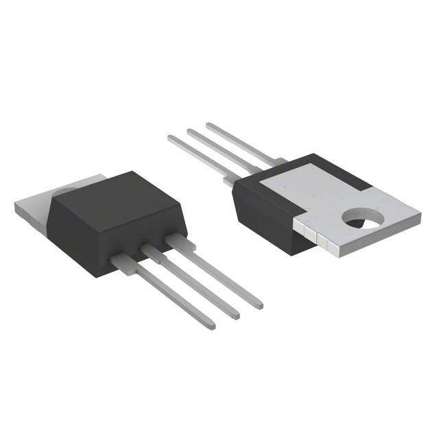
ICGOO电子元器件商城为您提供S6008R由Littelfuse设计生产,在icgoo商城现货销售,并且可以通过原厂、代理商等渠道进行代购。 S6008R价格参考。LittelfuseS6008R封装/规格:晶闸管 - SCR, SCR 600V 8A Standard Recovery Through Hole TO-220 Non-Isolated Tab。您可以下载S6008R参考资料、Datasheet数据手册功能说明书,资料中有S6008R 详细功能的应用电路图电压和使用方法及教程。
Littelfuse Inc. 是一家知名的电子元件制造商,其晶闸管(SCR)型号 S6008R 是一款常用于电力控制与开关应用的半导体器件。该器件具有600V的阻断电压和8A的通态平均电流能力,适用于多种中低功率的交流电力控制场景。

S6008R 的典型应用场景包括:

1. 家电控制:如电热水壶、电暖器、洗衣机等家用电器中的温度、电机或加热元件的交流电源控制。

2. 工业自动化:用于工业设备中的交流电机控制、电热控制、照明调光等,实现无触点开关功能,提高系统寿命和可靠性。

3. 照明控制:在调光系统、智能照明或舞台灯光系统中,作为可控硅调光器件使用。

4. 电源管理:在UPS(不间断电源)、电源切换系统中作为交流电源切换元件。

5. 电动工具与小功率电机控制:用于控制电动工具的速度或启停,具备较好的过载和短路保护配合能力。

S6008R因其高可靠性和良好的过载能力,广泛应用于需要交流负载控制的场合,尤其适合需要长寿命、高稳定性的电子产品中。
| 参数 | 数值 |
| 产品目录 | |
| 描述 | SCR NON-SENSITIVE GATE 8.0A 600VSCR 8A 600V |
| 产品分类 | SCR - 单个分离式半导体 |
| GateTriggerCurrent-Igt | 15 mA |
| GateTriggerVoltage-Vgt | 1.5 V |
| 品牌 | Littelfuse |
| 产品手册 | |
| 产品图片 |
|
| rohs | 符合RoHS无铅 / 符合限制有害物质指令(RoHS)规范要求 |
| 产品系列 | 晶体闸流管,SCR,Littelfuse S6008R- |
| 数据手册 | |
| 产品型号 | S6008R |
| SCR类型 | 标准恢复型 |
| 不重复通态电流 | 100 A |
| 产品目录页面 | |
| 产品种类 | SCR |
| 供应商器件封装 | TO-220(非隔离式)标片 |
| 保持电流Ih最大值 | 30 mA |
| 关闭状态漏泄电流(在VDRMIDRM下) | 0.01 mA |
| 包装 | 散装 |
| 商标 | Littelfuse |
| 安装类型 | 通孔 |
| 安装风格 | Through Hole |
| 封装 | Bulk |
| 封装/外壳 | TO-220-3 |
| 封装/箱体 | TO-220 |
| 工作温度 | -40°C ~ 125°C |
| 工厂包装数量 | 500 |
| 开启状态RMS电流-ItRMS | 8 A |
| 最大工作温度 | + 125 C |
| 最小工作温度 | - 40 C |
| 栅极触发电压-Vgt | 1.5 V |
| 栅极触发电流-Igt | 15 mA |
| 标准包装 | 500 |
| 正向电压下降 | 1.6 V |
| 电压-断态 | 600V |
| 电压-栅极触发(Vgt)(最大值) | 1.5V |
| 电压-通态(Vtm)(最大值) | 1.6V |
| 电流-不重复浪涌50、60Hz(Itsm) | 83A,100A |
| 电流-保持(Ih)(最大值) | 30mA |
| 电流-断态(最大值) | 10µA |
| 电流-栅极触发(Igt)(最大值) | 15mA |
| 电流-通态(It(AV))(最大值) | 5.1A |
| 电流-通态(It(RMS))(最大值) | 8A |
| 系列 | Sxx08x |
| 额定重复关闭状态电压VDRM | 600 V |


- 商务部:美国ITC正式对集成电路等产品启动337调查
- 曝三星4nm工艺存在良率问题 高通将骁龙8 Gen1或转产台积电
- 太阳诱电将投资9.5亿元在常州建新厂生产MLCC 预计2023年完工
- 英特尔发布欧洲新工厂建设计划 深化IDM 2.0 战略
- 台积电先进制程称霸业界 有大客户加持明年业绩稳了
- 达到5530亿美元!SIA预计今年全球半导体销售额将创下新高
- 英特尔拟将自动驾驶子公司Mobileye上市 估值或超500亿美元
- 三星加码芯片和SET,合并消费电子和移动部门,撤换高东真等 CEO
- 三星电子宣布重大人事变动 还合并消费电子和移动部门
- 海关总署:前11个月进口集成电路产品价值2.52万亿元 增长14.8%


PDF Datasheet 数据手册内容提取
Thyristors 8 Amp Sensitive & Standard SCRs Sxx08xSx & Sxx08x Series RoHS Description This Sxx08x SCR series is ideal for uni-directional switch applications such as phase control, heating, motor speed controls, converters/rectifiers and capacitive discharge ignitions. These SCRs have a low gate current trigger level of 0.2 to 15 mA at approximately 1.5V, with a sensitive version of this series having a gate trigger current less than 500µA. The sensitive gate SCR version is easily triggered by sense coils, proximity switches, and microprocessors. Features & Benefits • Halogen Free and • Surge capability up RoHS compliant to 100 A at 60 Hz Agency Approval • Glass – passivated half cycle junctions • L - Package is UL Agency Agency File Number recognized for 2500Vrms • Voltage capability up L Package: E71639 to 1000 V Applications Main Features Typical applications are capacitive discharge systems for strobe lights, nailers, staplers and gas engine ignition. Also Symbol Value Unit AC control & rectification for power tools, home/brown I 8 A goods, white goods appliances and 2-wheeler rectifier/ T(RMS) battery regulators. V /V 400 to 1000 V DRM RRM Internally constructed isolated packages are offered for I 0.2 to 15 mA ease of heat sinking with highest isolation voltage. GT Schematic Symbol Additional Information A K Datasheet Resources Samples G © 2018 Littelfuse, Inc. Specifications are subject to change without notice. Revised: 01/16/18
Thyristors 8 Amp Sensitive & Standard SCRs Absolute Maximum Ratings — Sensitive SCRs Symbol Parameter Test Conditions Value Unit Sxx08LSy T = 80°C C Sxx08RSy/Sxx08NSy I RMS on-state current 8 A T(RMS) Sxx08DSy T = 95°C C Sxx08VSy Sxx08LSy T = 80°C C Sxx08RSy/Sxx08NSy I Average on-state current 5.1 A T(AV) Sxx08DSy T = 95°C C Sxx08VSy single half cycle; f = 50Hz; 83 T (initial) = 25°C I Peak non-repetitive surge current J A TSM single half cycle; f = 60Hz; 100 T (initial) = 25°C J I2t I2t Value for fusing t = 8.3 ms 41 A2s p di/dt Critical rate of rise of on-state current f = 60 Hz ; T = 110°C 70 A/μs J I Peak gate current T = 110°C 1.6 A GTM J P Average gate power dissipation T = 110°C 0.4 W G(AV) J T Storage temperature range -40 to 150 °C stg T Operating junction temperature range -40 to 110 °C J Note: xx = voltage, y = sensitivity Absolute Maximum Ratings — Standard SCRs Symbol Parameter Test Conditions Value Unit Sxx08L T = 100°C C I RMS on-state current Sxx08R/Sxx08N 8 A T(RMS) Sxx08D T = 110°C C Sxx08V Sxx08L T = 100°C C I Average on-state current Sxx08R/Sxx08N 5.1 A T(AV) Sxx08D T = 110°C C Sxx08V single half cycle; f = 50Hz; 83 T (initial) = 25°C I Peak non-repetitive surge current J A TSM single half cycle; f = 60Hz; 100 T (initial) = 25°C J I2t I2t Value for fusing t = 8.3 ms 41 A2s p di/dt Critical rate-of-rise of on-state current f = 60 Hz T = 125°C 100 A/μs J I Peak gate current T = 125°C 2 A GM J P Average gate power dissipation T = 125°C 0.5 W G(AV) J T Storage temperature range -40 to 150 °C stg T Operating junction temperature range -40 to 125 °C J Note: xx = voltage © 2018 Littelfuse, Inc. Specifications are subject to change without notice. Revised: 01/16/18
Thyristors 8 Amp Sensitive & Standard SCRs Electrical Characteristics (T = 25°C, unless otherwise specified) – Sensitive SCRs J Value Symbol Test Conditions Unit Sxx08xS1 Sxx08xS2 Sxx08xS3 Sxx08x4 I V = 6V R = 100 Ω MAX. 50 200 500 100 μA GT D L V V = 6V R = 100 Ω MAX. 0.8 V GT D L dv/dt V = V ; R = 1kΩ; T = 110°C TYP. 8 V/μs D DRM GK J V V = V R = 3.3 kΩ T = 110°C MIN. 0.2 V GD D DRM L J V I = 10μA MIN. 6 V GRM GR I I = 20mA (initial) MAX. 4 6 8 5 mA H T t I=2A; t=50µs; dv/dt=5V/µs; di/dt=-30A/µs MAX. 75 50 45 60 μs q T p t I = 2 x I PW = 15µs I = 12A TYP. 3 4 5 4 μs gt G GT T Note: xx = voltage x = package Electrical Characteristics (T = 25°C, unless otherwise specified) – Standard SCRs J Value Symbol Test Conditions Unit Sxx08x I V = 12V R = 60 Ω MAX. 15 mA GT D L V V = 12V R = 60 Ω MAX. 1.5 V GT D L 400V 350 600V 300 V = V ; gate open; T = 100°C D DRM J 800V 250 dv/dt 1000V MIN. 100 V/μs 400V 250 V = V ; gate open; T = 125°C 600V 225 D DRM J 800V 200 V V = V R = 3.3 kΩ T = 125°C MIN. 0.2 V GD D DRM L J I I = 200mA (initial) MAX. 30 mA H T t I=2A; t=50µs; dv/dt=5V/µs; di/dt=-30A/µs MAX. 35 μs q T p t I = 2 x I PW = 15µs I = 16A TYP. 2 μs gt G GT T Note: xx = voltage x = package Static Characteristics Symbol Test Conditions Value Unit V I = 16A; t = 380 µs MAX. 1.6 V TM T p T = 25°C 400 - 600V 5 Sxx08xyy J T = 110°C 400 - 600V 250 J 400 - 800V 10 T = 25°C I / I V = V J 1000V MAX. 20 μA DRM RRM DRM RRM Sxx08x 400 - 800V 200 T = 100°C J 1000V 3000 T = 125°C 400 - 800V 500 J Note: xx = voltage, x = package, yy = sensitivity © 2018 Littelfuse, Inc. Specifications are subject to change without notice. Revised: 01/16/18
Thyristors 8 Amp Sensitive & Standard SCRs Thermal Resistances Symbol Parameter Value Unit Sxx08RSy / Sxx08NSy 1.8 Sxx08LSy 3.4 Sxx08VSy 2.1 Sxx08DSy 1.5 R Junction to case (AC) °C/W θ(J-C) Sxx08R / S xx08N 1.8 Sxx08L 3.4 Sxx08V 2.0 Sxx08D 1.5 Sxx08RSy 40 Sxx08LSy 65 Sxx08VSy 85 R Junction to ambient °C/W θ(J-A) Sxx08R 40 Sxx08L 50 Sxx08V 70 Note: xx = voltage, y = sensitivity Figure 1: Normalized DC Gate Trigger Current Figure 2: Normalized DC Gate Trigger Current vs. Junction Temperature (Sensitive SCR) vs. Junction Temperature (Standard SCR) 4.0 4.0 25°C) 3.0 = 25°C) 3.0 atio of I/ I (T = GT GTJ 12..00 Ratio of I / I (T GTGTJ 12..00 R 0.0 0.0 -40 -15 10 35 60 85 110 -40 -15 10 35 60 85 110 125 Junction Temperature (TJ) - (°C) Junction Temperature (TJ) - (°C) © 2018 Littelfuse, Inc. Specifications are subject to change without notice. Revised: 01/16/18
Thyristors 8 Amp Sensitive & Standard SCRs Figure 3: Normalized DC Gate Trigger Voltage Figure 4: Normalized DC Holding Current vs. Junction Temperature vs. Junction Temperature 2.0 2.0 atio of V / V (T= 25°C)GTGTJ 011...505 Ratio of I / I (T = 25°C)HHJ 011...505 R 0.0 0.0 -40 -15 10 35 60 85 110 125 -40 -15 10 35 60 85 110 125 Junction Temperature (TJ) - (°C) Junction Temperature (TJ) - (°C) Figure 5: On-State Current Figure 6: Power Dissipation (Typical) vs. On-State Voltage (Typical) vs. RMS On-State Current 32 8 s Amp 28 TJ = 25°C on 7 Current (i) – T 2204 wer DissipatiWatts) 56 antaneous On-state 114826 Average On-State Po [P] -- (D(AV) 1234 st n I 0 0 0.7 0.8 0.9 1.0 1.1 1.2 1.3 1.4 1.5 1.6 0 1 2 3 4 5 6 7 8 Instantaneous On-state Voltage (v) – Volts RMS On-State Current [I ] - (Amps) T T(RMS) Figure 7: Maximum Allowable Case Temperature Figure 8: Maximum Allowable Case Temperature vs. RMS On-State Current vs. Average On-State Current 130 130 mum Allowable Casemperature (T) - °CC111111001122050505 SSSSSxxxxxxxxxx00000888RN88SVRDSyySSS/yyy SSSSxxxxxxxx0000888R8/DRVSxx08N Sxx08L wable Case Temperature (T) - °CC111111110022055005 SSSSSxxxxxxxxxx000008888RN8SRDVSyySSS/yyy SSSSxxxxxxxx000088R88R/DVSxx08N Sxx08L Maxi Te 9905 CLOUARDR:E NRTes WisAtiVvEe FoOr RInMd:u cStiinvuesoidal Sxx08LSy mum Allo 9905 CLOUARDR:E NRTes WisAtiVvEe FoOr RInMd:u cStiinvuesoidal Sx08LSy 85 CFRoEnEd uAcItRio RnA ATnINgGle: 180° Maxi 85 CFRoEnEd uAcItRio RnA ATnINgGle: 180° 80 80 0 1 2 3 4 5 6 7 8 9 0 1 2 3 4 5 RMS On-State Current [I ] - Amps Average On-State Current [I ] - Amps T(RMS) T(AVE) © 2018 Littelfuse, Inc. Specifications are subject to change without notice. Revised: 01/16/18
Thyristors 8 Amp Sensitive & Standard SCRs Figure 9: Maximum Allowable Ambient Temperature Figure 10: Maximum Allowable Ambient Temperature vs. RMS On-State Current vs. Average On-State Current mperature 110200 Sxx08R CLCFORUOEARNEDRD A:EU RINRCeT TsR WiIsAOtATNivIVN eAE GNoFOrG IRLnMEd:u :1 cS8tii0nv°uesoidal mperature 110200 Sxx08R CLCFORUOEARNEDRD A:EU RINRCeT TsR WiIsAOtATNivIVN eAE GNoFOrG IRLnMEd:u :1 cS8tii0nv°uesoidal wable Ambient Te (T) - °CA6800 SSxxxx0088RLSSyy Sxx08L Sxx08V wable Ambient Te (T) - °CA6800 SSxxxx0088RLSSyy Sxx08L Sxx08V m Allo 40 m Allo 40 mu 20 Sxx08VSy mu 20 Sxx08VSy Maxi Maxi 0 0 0.0 0.5 1.0 1.5 2.0 2.5 0.0 0.5 1.0 1.5 RMS On-State Current [I ] - Amps Average On-State Current [I ] - Amps T(RMS) T(AVE) Note: xx = voltage, y = sensitivity Figure 11: Peak Capacitor Discharge Current Figure 12: Peak Capacitor Discharge Current Derating 1000 1.2 1.0 nt emps urre 0.8 Peak Dischargurrent (I) - ATM100 malized Peak C 00..46 C ITRM Nor Sensitive SCR Standard SCR 0.2 tW 10 0.0 0.5 1.0 10.0 50.0 0 25 50 75 100 125 150 Pulse Current Duration (tw) - ms Case Temperature (TC) - °C Figure 13-1: Typical DC Gate Trigger Current with R Figure 13-2: Typical DC Gate Trigger Current with R GK GK vs. Junction Temperature for S6008xS2 vs. Junction Temperature for S6008xS3 © 2018 Littelfuse, Inc. Specifications are subject to change without notice. Revised: 01/16/18
Thyristors 8 Amp Sensitive & Standard SCRs Figure 14-1: Typical DC Holding Current with R Figure 14-1: Typical DC Holding Current with R GK GK vs. Junction Temperature for S6008xS2 vs. Junction Temperature for S6008xS3 Figure 15-1: Typical Static dv/dt with R vs. Junction Figure 15-2: Typical Static dv/dt with R vs. Junction GK GK Temperature for S6008xS2 Temperature for S6008xS3 Figure 16-1: Typical turn off time with R vs. Junction Figure 16-2: Typical DC Gate Trigger Current with R GK GK Temperature for S6008xS2 vs. Junction Temperature for S6008xS3 © 2018 Littelfuse, Inc. Specifications are subject to change without notice. Revised: 01/16/18
Thyristors 8 Amp Sensitive & Standard SCRs Figure 17: Surge Peak On-State Current vs. Number of Cycles 100 SUPPLY FREQUENCY: 60 Hz Sinusoidal LOAD: Resistive RMS On-State Current: [I ]: Maximum Rated e T(RMS) at Value at Specified Case Temperature n-st ve)Omps Notes: urge (Non-repetitiCurrent (I) – ATSM 10 12.. Gf Otroeaavtlmleteoedprw l ecoviornaaandgltut umrserou.ealr ymgh eana soyc t urb erberteeu l nrornets eptind edt aetuotrrev insdatg le.u aanndtidyl - jsiumtnamctetei o dnia tely S k a e P 1 1 10 100 1000 Surge Current Duration -- Full Cycles Soldering Parameters Reflow Condition Pb – Free assembly t P T P - Temperature Min (T ) 150°C s(min) e RRaammpp--uupp Pre Heat -- TTeimmep e(mraitnu rteo Mmaaxx )( T(ts()max)) 2600 0–° C180 secs rutare TS(mTaxL) tL s p m RRaammpp--ddoown Average ramp up rate (Liquidus Temp) PPrreehheeaatt 5°C/second max e (TL) to peak T TS(min) t T to T - Ramp-up Rate 5°C/second max S S(max) L - Temperature (T) (Liquidus) 217°C Reflow L 25 - Temperature (t) 60 – 150 seconds time to peak temperature L Time Peak Temperature (T) 260+0/-5 °C P Time within 5°C of actual peak 20 – 40 seconds Temperature (t) p Ramp-down Rate 5°C/second max Time 25°C to peak Temperature (T) 8 minutes Max. P Do not exceed 280°C © 2018 Littelfuse, Inc. Specifications are subject to change without notice. Revised: 01/16/18
Thyristors 8 Amp Sensitive & Standard SCRs Physical Specifications Environmental Specifications Test Specifications and Conditions Terminal Finish 100% Matte Tin-plated MIL-STD-750, M-1040, Cond A Applied AC Blocking Peak AC voltage @ 125°C for 1008 hours UL recognized epoxy meeting flammability Body Material MIL-STD-750, M-1051, rating 94V-0 Temperature Cycling 100 cycles; -40°C to +150°C; 15-min dwell-time Lead Material Copper Alloy EIA / JEDEC, JESD22-A101 Temperature/ 1008 hours; 320V - DC: 85°C; 85% Humidity rel humidity MIL-STD-750, M-1031, Design Considerations High Temp Storage 1008 hours; 150°C Careful selection of the correct component for the Low-Temp Storage 1008 hours; -40°C application’s operating parameters and environment will Resistance to go a long way toward extending the operating life of the MIL-STD-750 Method 2031 Solder Heat Thyristor. Good design practice should limit the maximum continuous current through the main terminals to 75% of Solderability ANSI/J-STD-002, category 3, Test A the component rating. Other ways to ensure long life for Lead Bend MIL-STD-750, M-2036 Cond E a power discrete semiconductor are proper heat sinking and selection of voltage ratings for worst case conditions. Overheating, overvoltage (including dv/dt), and surge currents are the main killers of semiconductors. Correct mounting, soldering, and forming of the leads also help protect against component damage. © 2018 Littelfuse, Inc. Specifications are subject to change without notice. Revised: 01/16/18
Thyristors 8 Amp Sensitive & Standard SCRs Dimensions — TO-220AB (R-Package) — Non-Isolated Mounting Tab Common with Center Lead Inches Millimeters TC MEASURING POINT AREA (REF.) 0.17 IN2 Dimension O Min Max Min Max E A P .83.2130 A 0.380 0.420 9.65 10.67 ANODE B B 0.105 0.115 2.67 2.92 C 13.36 C 0.230 0.250 5.84 6.35 D .526 D 0.590 0.620 14.99 15.75 7.01 .276 E 0.142 0.147 3.61 3.73 F 0.110 0.130 2.79 3.30 F NOTCH IN GATE LEAD G 0.540 0.575 13.72 14.61 TO ID. NON-ISOLATED R TAB H 0.025 0.035 0.64 0.89 G L J 0.195 0.205 4.95 5.21 H K 0.095 0.105 2.41 2.67 CATHODE ANODE GATE L 0.060 0.075 1.52 1.91 N K J M Note: Maximum torque to M 0.085 0.095 2.16 2.41 be applied to mounting tab is 8 in-lbs. (0.904 Nm). N 0.018 0.024 0.46 0.61 O 0.178 0.188 4.52 4.78 P 0.045 0.060 1.14 1.52 R 0.038 0.048 0.97 1.22 Dimensions — TO-220AB (L-Package) — Isolated Mounting Tab Inches Millimeters TC MEASURING POINT AREA (REF.) 0.17 IN2 Dimension O Min Max Min Max E A P .83.2130 A 0.380 0.420 9.65 10.67 B B 0.105 0.115 2.67 2.92 C 13.36 C 0.230 0.250 5.84 6.35 D .526 D 0.590 0.620 14.99 15.75 7.01 .276 E 0.142 0.147 3.61 3.73 F 0.110 0.130 2.79 3.30 F G 0.540 0.575 13.72 14.61 R H 0.025 0.035 0.64 0.89 G L J 0.195 0.205 4.95 5.21 H K 0.095 0.105 2.41 2.67 CATHODE ANODE GATE L 0.060 0.075 1.52 1.91 K N Note: Maximum torque to J M be applied to mounting tab M 0.085 0.095 2.16 2.41 is 8 in-lbs. (0.904 Nm). N 0.018 0.024 0.46 0.61 O 0.178 0.188 4.52 4.78 P 0.045 0.060 1.14 1.52 R 0.038 0.048 0.97 1.22 © 2018 Littelfuse, Inc. Specifications are subject to change without notice. Revised: 01/16/18
Thyristors 8 Amp Sensitive & Standard SCRs Dimensions — TO-251AA (V/I-Package) — V/I-PAK Through Hole T MEASURING POINT AREA: 0.040 IN2 Inches Millimeters C Dimension Min Typ Max Min Typ Max Anode E H 5.28 D J .208 A 0.037 0.040 0.043 0.94 1.01 1.09 B 0.235 0.242 0.245 5.97 6.15 6.22 A 5.34 C 0.350 0.361 0.375 8.89 9.18 9.53 .210 D 0.205 0.208 0.213 5.21 5.29 5.41 B E 0.255 0.262 0.265 6.48 6.66 6.73 P R F 0.027 0.031 0.033 0.69 0.80 0.84 S Q G 0.087 0.090 0.093 2.21 2.28 2.36 K H 0.085 0.092 0.095 2.16 2.34 2.41 C I 0.176 0.180 0.184 4.47 4.57 4.67 J 0.018 0.020 0.023 0.46 0.51 0.58 K 0.035 0.037 0.039 0.90 0.95 1.00 Cathode F L L 0.018 0.020 0.023 0.46 0.52 0.58 Anode G GATE P 0.042 0.047 0.052 1.06 1.20 1.32 I Q 0.034 0.039 0.044 0.86 1.00 1.11 R 0.034 0.039 0.044 0.86 1.00 1.11 S 0.074 0.079 0.084 1.86 2.00 2.11 Dimensions — TO-252AA (D-Package) — D-PAK Surface Mount Anode DE TC MEASURING POINT .52.0288 .62.6741 Dimension Inches Millimeters Min Typ Max Min Typ Max A 5.34 6.71 A 0.037 0.040 0.043 0.94 1.01 1.09 .210 .264 B B 0.235 0.243 0.245 5.97 6.16 6.22 1.60 C 0.106 0.108 0.113 2.69 2.74 2.87 P .063 C Q D 0.205 0.208 0.213 5.21 5.29 5.41 1.80 GATE .071 E 0.255 0.262 0.265 6.48 6.65 6.73 Cathode F AREA: 0.040 IN2 Anode G .1138 .41.8610 F 0.027 0.031 0.033 0.69 0.80 0.84 I G 0.087 0.090 0.093 2.21 2.28 2.36 O L H 0.085 0.092 0.095 2.16 2.33 2.41 K J H I 0.176 0.179 0.184 4.47 4.55 4.67 M J 0.018 0.020 0.023 0.46 0.51 0.58 N K 0.035 0.037 0.039 0.90 0.95 1.00 L 0.018 0.020 0.023 0.46 0.51 0.58 M 0.000 0.000 0.004 0.00 0.00 0.10 N 0.021 0.026 0.027 0.53 0.67 0.69 O 0° 0° 5° 0° 0° 5° P 0.042 0.047 0.052 1.06 1.20 1.32 Q 0.034 0.039 0.044 0.86 1.00 1.11 © 2018 Littelfuse, Inc. Specifications are subject to change without notice. Revised: 01/16/18
Thyristors 8 Amp Sensitive & Standard SCRs Product Selector Voltage Part Number Gate Sensitivity Type Package 400V 600V 800V 1000V Sxx08RS2 X X 0.2mA Sensitive SCR TO-220R Sxx08LS2 X X 0.2mA Sensitive SCR TO-220L Sxx08VS2 X X 0.2mA Sensitive SCR TO-251 Sxx08DS2 X X 0.2mA Sensitive SCR TO-252 Sxx08RS3 X X 0.5mA Sensitive SCR TO-220R Sxx08LS3 X X 0.5mA Sensitive SCR TO-220L Sxx08VS3 X X 0.5mA Sensitive SCR TO-251 Sxx08DS3 X X 0.5mA Sensitive SCR TO-252 Sxx08R X X X X 15mA Standard SCR TO-220R Sxx08L X X X X 15mA Standard SCR TO-220L Sxx08V X X X X 15mA Standard SCR TO-251 Sxx08D X X X X 15mA Standard SCR TO-252 Sxx08NS2 X X 0.2mA Sensitive SCR TO-263 Sxx08NS3 X X 0.5mA Sensitive SCR TO-263 Sxx08N X X X X 15mA Standard SCR TO-263 Sxx08DS1 X 50µA Sensitive SCR TO-252 Sxx08DS4 X 100µA Sensitive SCR TO-252 Note: xx = Voltage/10 Packing Options Part Number Marking Weight Packing Mode Base Quantity Sxx08L/RyyTP Sxx08L/Ryy 2.2 g Tube 500 (50 per tube) Sxx08DyyTP Sxx08Dyy 0.3 g Tube 750 (75 per tube) Sxx08DyyRP Sxx08Dyy 0.3 g Embossed Carrier 2500 Sxx08VyyTP Sxx08Vyy 0.4 g Tube 750 (75 per tube) Sxx08L/RTP Sxx08L/R 2.2 g Tube 500 (50 per tube) Sxx08DTP Sxx08D 0.3 g Tube 750 (75 per tube) Sxx08DRP Sxx08D 0.3 g Embossed Carrier 2500 Sxx08NyyTP Sxx08Nyy 1.6g Tube 500 (50 per tube) Sxx08NyyRP Sxx08Nyy 1.6g Embossed Carrier 500 Sxx08VyyNTP Sxx08N 1.6g Tube 500 (50 per tube) Sxx08NTP Sxx08N 1.6g Embossed Carrier 500 Sxx08NRP Sxx08V 0.4 g Tube 750 (75 per tube) Note: xx = Voltage/10; yy = Sensitivity © 2018 Littelfuse, Inc. Specifications are subject to change without notice. Revised: 01/16/18
Thyristors 8 Amp Sensitive & Standard SCRs TO-252 Embossed Carrier Reel Pack (RP) Specifications Meets all EIA-481-2 Standards 0.157 0.059 DIA (4.0) (1.5) Gate Cathode (016.6.03) (01.35.234)* XXXXXX XXDC XXXXXX XXDC XXXXXX XXDC XXXXXX * Cover tape 0.315 Anode (8.0) 12.99 0.512 (13.0) (330.0) Dimensions Arbor Hole are in inches Diameter (and millimeters). 0.64 (16.3) Direction of Feed TO-202 Type 1 (F Package) TO-202 Type 1 (F Package) Part Numbering System Part Marking System S 60 08 L S2 56 S6008F1 TO-251AA - (V Package) TO-252AA - (D Package) CODMESPVO: I NC SEECN TRT YTPYPEE ® yxxxLxEAD FORM DIMENSIONS S600S86D0S028F1 S6008DS2 TTOO--225512AAAA -- ((VD PPaacckkaaggee)) xx: Lead Form Option yxxxx VOLTAGE RATING ® S6008DS2 S6008DS2 40: 400V SENSITIVITY & TYPE 60: 600V SeSnesintisvieti SvCeR S:CR:Standard SCR: YMLDD ® YMLDD ® 80: 800V S1:S 520:µ A200µA {blank} 15mA K0: 1000V S2:S 230:0 µ5A00µA Date Code Marking CU08R:R 8EANT RATING TO-220 ASSS34Bt::( a51b n00-la 00d(nµµaLAAkr d)a: S n1C5dRm :RA Package) YMLD::D :YL :Meo Cacoaran ltCetiohnon ddC aeCorod Cdeoede YMLDD ® YMLDD ® PACKAGE TYPE Date Code Marking L: TO-220 Isolated TO-263 AA (N Package) Y:Year Code RVS::6 YTT0MOO0--X22825XR01XS N(V2o/In-P-Iasko)lated TO-220 AB - (L and R Package) ML: :L Mocoanttiohn C Cooddee D: TO-252 (D-Pak) DD: Calendar Code N: TO-263 (D2PAK) ® Date Code Marking S6008RS2 Y:Year Code YMXXX M: Month Code XXX: Lot Trace Code ® Date Code Marking Y:Year Code M: Month Code XXX: Lot Trace Code © 2018 Littelfuse, Inc. Specifications are subject to change without notice. Revised: 01/16/18