ICGOO在线商城 > NME0509SC

 Datasheet下载
- 型号: NME0509SC
- 制造商: Murata
- 库位|库存: xxxx|xxxx
- 要求:
| 数量阶梯 | 香港交货 | 国内含税 |
| +xxxx | $xxxx | ¥xxxx |
查看当月历史价格
查看今年历史价格
NME0509SC产品简介:
ICGOO电子元器件商城为您提供NME0509SC由Murata设计生产,在icgoo商城现货销售,并且可以通过原厂、代理商等渠道进行代购。 提供NME0509SC价格参考以及MurataNME0509SC封装/规格参数等产品信息。 你可以下载NME0509SC参考资料、Datasheet数据手册功能说明书, 资料中有NME0509SC详细功能的应用电路图电压和使用方法及教程。
| 参数 | 数值 |
| 产品目录 | |
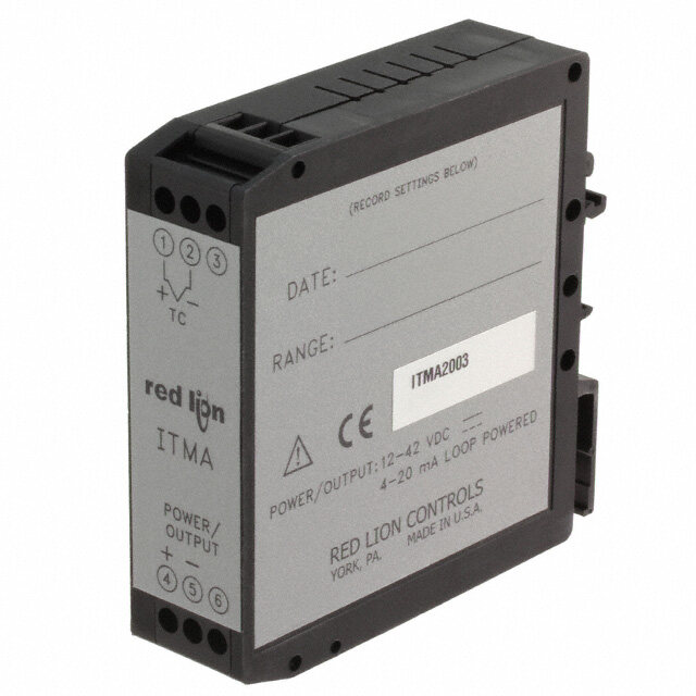
| 描述 | CONV DC/DC 1W 5VIN 9VOUT SIP SGL隔离式DC/DC转换器 5V to 9V 111mA SIP |
| 产品分类 | DC DC ConvertersDC/DC转换器 |
| 品牌 | Murata Power Solutions Inc |
| 产品手册 | |
| 产品图片 |
|
| rohs | RoHS 合规性豁免无铅 / 符合限制有害物质指令(RoHS)规范要求 |
| 产品系列 | 隔离式DC/DC转换器,Murata Power Solutions NME0509SCNME |
| 数据手册 | |
| 产品型号 | NME0509SC |
| 产品 | Isolated |
| 产品培训模块 | http://www.digikey.cn/PTM/IndividualPTM.page?site=cn&lang=zhs&ptm=21791 |
| 产品目录页面 | |
| 产品种类 | 隔离式DC/DC转换器 |
| 其它名称 | 811-1476-5 |
| 功率(W)-制造系列 | 1W |
| 功率(W)-最大值 | 1W |
| 包装 | 管件 |
| 商标 | Murata Power Solutions |
| 大小/尺寸 | 0.45" 长 x 0.24" 宽 x 0.39" 高(11.4mm x 6.1mm x 9.9mm) |
| 安装类型 | 通孔 |
| 安装风格 | Through Hole |
| 宽度 | 0.45 in |
| 封装 | Tube |
| 封装/外壳 | 4-SIP 模块 |
| 封装/箱体尺寸 | SIP-4 |
| 尺寸 | 0.24 in x 0.45 in x 0.39 in |
| 工作温度 | -40°C ~ 85°C |
| 工厂包装数量 | 35 |
| 效率 | 77% |
| 标准包装 | 35 |
| 特性 | - |
| 电压-输入(最大值) | 5.5V |
| 电压-输入(最小值) | 4.5V |
| 电压-输出1 | 9V |
| 电压-输出2 | - |
| 电压-输出3 | - |
| 电压-隔离 | 1kV(1000V) |
| 电流-输出(最大值) | 111mA |
| 类型 | 隔离模块 |
| 系列 | NME |
| 绝缘电压 | 1 kV |
| 输入电压—公称值 | 5 V |
| 输入电压范围 | 4.5 V to 5.5 V |
| 输出功率 | 1 W |
| 输出数 | 1 |
| 输出电压—通道1 | 9 V |
| 输出电流—通道1 | 111 mA |
| 输出端数量 | 1 |
| 长度 | 0.24 in |
| 高度 | 0.39 in |


- 商务部:美国ITC正式对集成电路等产品启动337调查
- 曝三星4nm工艺存在良率问题 高通将骁龙8 Gen1或转产台积电
- 太阳诱电将投资9.5亿元在常州建新厂生产MLCC 预计2023年完工
- 英特尔发布欧洲新工厂建设计划 深化IDM 2.0 战略
- 台积电先进制程称霸业界 有大客户加持明年业绩稳了
- 达到5530亿美元!SIA预计今年全球半导体销售额将创下新高
- 英特尔拟将自动驾驶子公司Mobileye上市 估值或超500亿美元
- 三星加码芯片和SET,合并消费电子和移动部门,撤换高东真等 CEO
- 三星电子宣布重大人事变动 还合并消费电子和移动部门
- 海关总署:前11个月进口集成电路产品价值2.52万亿元 增长14.8%


PDF Datasheet 数据手册内容提取
NME Series www.murata-ps.com Isolated 1W Single Output DC-DC Converters SELECTION GUIDE Order Code Nominal Input VoltageOutput Voltage Output Current Input Current at Rated Load Load Regulation2 Ripple & Noise Efficiency (Min) Efficiency (Typ) Isolation Capacitance MTTF1 Package Style % mV p-p MIL. Tel. V V mA mA % pF Typ. Max. Typ. Max. kHrs FEATURES NME0505DC 5 5 200 286 12 14 16 40 69 30 3415 NME0509DC 5 9 111 260 8 9 60 75 77 37 3078 (cid:132)(cid:3)Short circuit protection options NME0512DC 5 12 83 256 6.5 7.5 50 65 78 33 2205 DIP (cid:132)(cid:3)UL 60950 recognised NME0515DC 5 15 67 250 6 7.5 10 25 80 40 1532 NME0524DC 5 24 42 248 5.5 7.5 140 180 80 48 (cid:132)(cid:3)Single isolated output NME0505SC 5 5 200 286 12 14 16 40 69 30 3415 (cid:132)(cid:3)1kVDC isolation ‘Hi Pot Test’ NME0509SC 5 9 111 260 8 9 60 75 77 37 3078 (cid:132)(cid:3)Wide temperature performance at full NME0512SC 5 12 83 256 6.5 7.5 50 65 78 33 2205 SIP NME0515SC 5 15 67 250 6 7.5 10 25 80 40 1532 1 watt load, –40°C to 85°C2 NME0524SC 5 24 42 248 5.5 7.5 140 180 80 48 (cid:132)(cid:3)Industry standard pinout NME1205DC 12 5 200 117 8 10 12 30 69 33 2493 (cid:132)(cid:3)5V, 12V, 15V & 24V input NME1212DC 12 12 83 104 4 5 8 20 76 55 1780 DIP NME1215DC 12 15 67 110 3 4 40 55 75 52 1313 (cid:132)(cid:3)5V, 9V, 12V and 15V output NME1205SC 12 5 200 117 8 10 12 30 69 33 2493 (cid:132)(cid:3)Fully encapsulated with toroidal magnetics NME1209SC 12 9 111 115 5 5.5 60 75 74 48 2311 NME1212SC 12 12 83 104 4 5 50 65 76 55 1780 SIP (cid:132)(cid:3)No external components required NME1215SC 12 15 67 111 3 4 40 55 75 52 1313 (cid:132)(cid:3)Pin compatible with CME, CRE1, CRL2, NME1515SC 15 15 67 81 2.5 3 150 82 LME, MEE1, MEE3, NKE & NML NME2405DC 24 5 200 58 8.5 10 150 70 40 201 NME2412DC 24 12 83 52 3 4 150 80 78 163 DIP DESCRIPTION NME2415DC 24 15 67 51 2.5 3 150 80 79 136 NME2405SC 24 5 200 58 8.5 10 150 70 40 201 The NME series of DC-DC Converters is particular- NME2412SC 24 12 83 52 3 4 150 80 78 163 SIP ly suited to isolating and/or converting DC power rails. The galvanic isolation allows the device to be NME2415SC 24 15 67 51 2.5 3 150 80 79 136 configured to provide an isolated negative rail in Short Circuit Protection Options systems where only positive rails exist. The wide NME0505SPC 5 5 200 255 9.5 12 11 25 75 77 22 288747047 SIP temperature range guarantees startup from –40°C NME0505DPC 5 5 200 255 9.5 12 11 25 75 77 22 288747047 DIP and full 1 watt output at 85°C2. For lower ripple, Recommended refer to output ripple reduction section. The NME Alternative series offers short circuit protection options (PC) NME1209DC 12 9 111 115 5 5.5 60 75 74 48 2311 DIP MEE1S1209DC across the operating temperature range. Short NME2409DC 24 9 111 54 4 5 150 75 59 185 MEE1S2409DC circuits of less than 1Ω cause the converter to en- NME2409SC 24 9 111 54 4 5 150 75 59 185 SIP MEE1S2409SC ter a ‘foldback’ limiting mode such that the input INPUT CHARACTERISTICS current is approximately 95mA for 0505 variant. Parameter Conditions Min. Typ. Max. Units Protection is continuous and auto-resetting on Continuous operation, 5V input types 4.5 5.0 5.5 removal of the short circuit. Continuous operation, 12V input types 10.8 12.0 13.2 Voltage range V Continuous operation, 15V input types 13.5 15 16.5 Continuous operation, 24V input types 21.6 24 26.4 Input short circuit current Short circuit variants 95 mA Short circuit variants 3 15 Input Reflected ripple 15V input type 90 mA p-p current All other variants3 26 48 1. Calculated using MIL-HDBK-217 FN2 and Telcordia SR-332 calculation model with nominal input voltage at full load. 2. NME1515SC, NME24XXXC prior to date code X1635 have operating temperature range of 0 to 70°C . For full details go to 3. Excludes 24V input types. www.murata-ps.com/rohs All specifications typical at TA=25°C, nominal input voltage and rated output current unless otherwise specified. www.murata-ps.com/support KDC_NME.I02 Page 1 of 11
NME Series Isolated 1W Single Output DC-DC Converters OUTPUT CHARACTERISTICS Parameter Conditions Min. Typ. Max. Units Rated Power See derating curves 1.0 W Voltage Set Point Accuracy See tolerance envelope High VIN to low VIN ; All short circuit types 1.15 1.2 Line regulation %/% High VIN to low VIN ; All other output types 1.0 1.2 ISOLATION CHARACTERISTICS Parameter Conditions Min. Typ. Max. Units Isolation test voltage Flash tested for 1 second 1000 VDC Resistance Viso= 1000VDC 10 GΩ GENERAL CHARACTERISTICS Parameter Conditions Min. Typ. Max. Units 5V input types 110 12V input types 145 Switching frequency 15V input types 100 kHz 24V input types 100 Short circuit types 91 TEMPERATURE CHARACTERISTICS Parameter Conditions Min. Typ. Max. Units Specification All output types1 -40 85 Storage -50 130 5V output types 41 Non-short circuit types °C All other output types2 32 Case Temperature above ambient Short circuit types (DIP) 23 Short circuit types (SIP) 24 Cooling Free air convection ABSOLUTE MAXIMUM RATINGS Lead temperature 1.5mm from case for 10 seconds 260°C Input voltage VIN, NME05 types 7V Input voltage VIN, NME12 types 15V Input voltage VIN, NME15 types 18V Input voltage VIN, NME24 types 28V TEMPERATURE DERATING GRAPH Non-short circuit types1: Short circuit types: 1.5 1.5 W)1.0 85°C W)1.0 85°C er ( er ( w w o o P P ut 0.5 Safe Operating Area ut 0.5 Safe Operating Area p p ut 120°C ut O O 0 0 -40 0 50 100 150 -40 0 50 100 150 Ambient Temperature (°C) Ambient Temperature (°C) 1. NME1515SC, NME24XXXC prior to date code X1635 have operating temperature range of 0 to 70°C . 2. Excludes 24V input types. www.murata-ps.com/support KDC_NME.I02 Page 2 of 11
NME Series Isolated 1W Single Output DC-DC Converters TECHNICAL NOTES ISOLATION VOLTAGE ‘Hi Pot Test’, ‘Flash Tested’, ‘Withstand Voltage’, ‘Proof Voltage’, ‘Dielectric Withstand Voltage’ & ‘Isolation Test Voltage’ are all terms that relate to the same thing, a test voltage, applied for a specified time, across a component designed to provide electrical isolation, to verify the integrity of that isolation. Murata Power Solutions NME series of DC-DC converters are all 100% production tested at their stated isolation voltage. This is 1kVDC for 1 second. A question commonly asked is, “What is the continuous voltage that can be applied across the part in normal operation?” The NME has been recognised by Underwriters Laboratory for functional insulation, both input and output should normally be maintained within SELV limits i.e. less than 42.4V peak, or 60VDC. The isolation test voltage represents a measure of immunity to transient voltages and the part should never be used as an element of a safety isolation system. The part could be expected to function correctly with several hundred volts offset applied continuously across the isolation barrier; but then the circuitry on both sides of the barrier must be regarded as operating at an unsafe voltage and further isolation/insulation systems must form a barrier between these circuits and any user-accessible circuitry according to safety standard requirements. REPEATED HIGH-VOLTAGE ISOLATION TESTING It is well known that repeated high-voltage isolation testing of a barrier component can actually degrade isolation capability, to a lesser or greater degree depending on materials, construction and environment. The NME series has toroidal isolation transformers, with no additional insulation between primary and secondary windings of enamelled wire. While parts can be expected to withstand several times the stated test voltage, the isolation capability does depend on the wire insulation. Any material, including this enamel (typically polyurethane) is susceptible to eventual chemical degradation when subject to very high applied voltages thus implying that the number of tests should be strictly limited. We therefore strongly advise against repeated high voltage isolation testing, but if it is absolutely required, that the voltage be reduced by 20% from specified test voltage. This consideration equally applies to agency recognised parts rated for better than functional isolation where the wire enamel insulation is always supplemented by a further insulation system of physical spacing or barriers. SAFETY APPROVAL The NME series has been recognised by Underwriters Laboratory (UL) to UL 60950 for functional insulation in a maximum ambient temperature of 85ºC and/or case temperature limit of 100ºC. Case temperature measured on the face opposite the pins. The NME Series of converters are not internally fused so to meet the requirements of UL 60950 an anti-surge input line fuse should always be used with ratings as defined below. NME05xxxxC: 0.5A NME12xxxxC: 0.25A NME15xxxxC: 0.2A NME24xxxxC: 0.12A All fuses should be UL recognised and rated at 125V. File number E151252 applies. RoHS COMPLIANCE INFORMATION This series is compatible with RoHS soldering systems with a peak wave solder temperature of 260°C for 10 seconds. The pin termination finish on the SIP package type is Tin Plate, Hot Dipped over Matte Tin with Nickel Preplate. The DIP types are Matte Tin over Nickel Preplate. Both types in this series are backward compatible with Sn/Pb soldering systems. For further information, please visit www.murata-ps.com/rohs www.murata-ps.com/support KDC_NME.I02 Page 3 of 11
NME Series Isolated 1W Single Output DC-DC Converters APPLICATION NOTES Minimum load The minimum load to meet datasheet specification is 10% of the full rated load across the specified input voltage range. Lower than 10% minimum loading will result in an increase in output voltage, which may rise to typically double the specified output voltage if the output load falls to less than 5%. Capacitive loading and start up Typical start up times for this series, with a typical input voltage rise time of 2.2μs and output capacitance of 10μF, are shown in the table below. The product series will start into a capacitance of 47μF with an increased start time, however, the maximum recommended output capacitance is 10μF. Start-up time μs NME0505XC 991 Typical Start-Up Wave Form NME0509XC 3524 NME0512XC 5630 NME0515XC 7750 NME0524XC 19850 NME1205XC 682 NME1209XC 2102 NME1212XC 4030 NME1215XC 6193 NME1515SC 685 NME2405XC 135 NME2409XC 260 NME2412XC 430 NME2415XC 640 NME0505XPC 350 Ripple & Noise Characterisation Method Ripple and noise measurements are performed with the following test configuration. C1 1μF X7R m ultilayer ceramic capacitor, voltage rating to be a minimum of 3 times the output voltage of the DC-DC converter 10μF tantalum capacitor, voltage rating to be a minimum of 1.5 times the output voltage of the DC-DC converter with an ESR of less C2 than 100mΩ at 100 kHz C3 100nF multilayer ceramic capacitor, general purpose R1 450Ω resistor, carbon film, ±1% tolerance R2 50Ω BNC termination T1 3T of the coax cable through a ferrite toroid RLOAD Resistive load to the maximum power rating of the DC-DC converter. Connections should be made via twisted wires Measured values are multiplied by 10 to obtain the specified values. Differential Mode Noise Test Schematic DC/DC Converter OSCILLOSCOPE C1 C2 C3 R1 T1 R2 + + Y INPUT SUPPLY Input Output - - R LOAD www.murata-ps.com/support KDC_NME.I02 Page 4 of 11
NME Series Isolated 1W Single Output DC-DC Converters APPLICATION NOTES (continued) Output Ripple Reduction By using the values of inductance and capacitance stated, the output ripple at the rated load is lowered to 5mV p-p max. Component selection Capacitor: It is required that the ESR (Equivalent Series Resistance) should be as low as possible, ceramic types are recommended. The voltage rating should be at least twice (except for 15V output), the rated output voltage of the DC-DC converter. Inductor: The rated current of the inductor should not be less than that of the output of the DC-DC converter. At the rated current, the DC resistance of the inductor should be such that the voltage drop across the inductor is <2% of the rated voltage of the DC-DC converter. The SRF (Self Resonant Frequency) should be >20MHz. L DC Power C Load Source DC Inductor Capacitor L, μH SMD Through Hole C, μF NME0505XC 47 82473C 11R473C 4.7uF NME0509XC 47 82473C 11R473C 1uF NME0512XC 68 82683C 11R683C 1uF NME0515XC 100 82104C 11R104C 0.47uF NME0524XC 100 82104C 11R104C 0.47 NME1205XC 100 82104C 11R104C 4.7uF NME1209XC 47 82473C 11R473C 1uF NME1212XC 68 82683C 11R683C 0.47uF NME1215XC 100 82104C 11R104C 0.47uF NME1515SC NME2405XC NME2409XC NME2412XC NME2415XC NME0505XPC 22 82223C 11R223C 1uF www.murata-ps.com/support KDC_NME.I02 Page 5 of 11
NME Series Isolated 1W Single Output DC-DC Converters TOLERANCE ENVELOPES The voltage tolerance envelope shows typical load regulation characteristics for this product series. The tolerance envelope is the maximum output voltage variation due to changes in output loading. 5V, 12V, 15V & 24V Input types Short circuit +10% +9% +5% Typical Load Line +2.5% V NOM -2.5% +4% ut Voltage -7.5% Output Voltage 0% p ut O 10 25 50 75 100 -6% Output Load Current (%) 10 25 50 75 100 Output Load Current (%) EFFICIENCY VS LOAD 5V & Short circuit input variants 12V Inputs 90 90 80 80 70 70 60 NME0505XC 60 Efficiency (%)345000 NNNNNMMMMMEEEEE00000555550112092545XXXXXCCCCPC Efficiency (%)345000 NNNNMMMMEEEE1111222200115925XXXXCCCC 20 20 10 10 0 0 0 10 20 30 40 50 60 70 80 90 100 0 10 20 30 40 50 60 70 80 90 100 Load (%) Load (%) 15V Inputs 24V Inputs 90 90 80 80 70 70 60 60 Efficiency (%)4500 NME1515SC Efficiency (%)4500 NNNNMMMMEEEE2222444400115925XXXXCCCC 30 30 20 20 10 10 0 0 0 10 20 30 40 50 60 70 80 90 100 0 10 20 30 40 50 60 70 80 90 100 Load (%) Load (%) www.murata-ps.com/support KDC_NME.I02 Page 6 of 11
NME Series Isolated 1W Single Output DC-DC Converters EMC FILTERING AND SPECTRA FILTERING The following table shows the additional input capacitor and input inductor typically required to meet EN 55022 Curve B Quasi-Peak EMC limit, as shown in the following plots. The following plots show positive and negative quasi peak and CISPR22 Average Limit B (pink line) and Quasi Peak Limit B (green line) adherence limits. L DC C DC C Ceramic capacitor Inductor Capacitor Inductor Capacitor Part Number L, μH SMD Through Hole C, μF Part Number L, μH SMD Through Hole C, μF NME0505XC 4.7 13R472C 4.7 NME1215XC NME0509XC NME1515SC NME0512XC NME2405XC 22 13R223C 10 NME0515XC 4.7 13R472C 4.7 NME2409XC NME0524XC NME2412XC 22 13R223C 10 NME1205XC 10 13R103C 1 NME2415XC NME1209XC NME0505XPC 10 82103C 13R103C 1 NME1212XC 10 13R103C 1 NME0505XC NME0509XC NME0512XC NME0515XC www.murata-ps.com/support KDC_NME.I02 Page 7 of 11
NME Series Isolated 1W Single Output DC-DC Converters EMC FILTERING AND SPECTRA NME0524XC NME0505XPC 80 70 60 50 V Bu 40 d 30 20 10 0 1.00E+05 1.00E+06 1.00E+07 1.00E+08 Frequency (Hz) NME1205XC NME1209XC NME1212XC NME1215XC www.murata-ps.com/support KDC_NME.I02 Page 8 of 11
NME Series Isolated 1W Single Output DC-DC Converters EMC FILTERING AND SPECTRA NME1515SC NME2405XC NME2409XC NME2412XC NME2415XC www.murata-ps.com/support KDC_NME.I02 Page 9 of 11
NME Series Isolated 1W Single Output DC-DC Converters PACKAGE SPECIFICATIONS MECHANICAL DIMENSIONS PIN CONNECTIONS - 8 PIN DIP Pin Function DIP Package SIP Package 1 -VIN 4 +VIN 11.6±0.15 [0.457±0.006] 5 +VOUT 7 -VOUT NME XXXXDC PIN CONNECTIONS - 4 PIN SIP 9.9±0.15 [0.390±0.006] Pin Function 11.53±0.2 [0.454±0.008] 1 -VIN NME 2 +VIN 6.9±0.15 [0.272±0.006] 10.00±0.25 [0.394±0.010] XXXXSC 0.40 [0.016] MIN S 34 +-VVOOUUTT 4.10±0.5 [0.161±0.020] 4.10±0.5 [0.161±0.020] 1 2 3 4 0.5±0.05 [0.020±0.002] 1.99±0.25 [0.078±0.010] 2.54 [0.100] 0.50±0.05 [0.020±0.002] 1 4 (2.21 [0.087]) 1.14±0.25 [0.045±0.010] 0.25±0.05 [0.010±0.002] 7.62 [0.300] 7 5 (1.13 [0.044]) 6.10+-00.2.105 [0.240+-00.0.00086] 0.25±0.05 [0.010±0.002] 5.08 [0.200] 7.62 [0.300] All dimensions in mm (inches) Controlling dimension is mm. All pins on a 2.54 (0.100) pitch and within ±0.1 (0.004) of true position from pin 1 at seating plane ‘S’ Weight: 1.30g (SIP) 1.48g (DIP) 1.5g (SP DIP) www.murata-ps.com/support KDC_NME.I02 Page 10 of 11
NME Series Isolated 1W Single Output DC-DC Converters PACKAGE SPECIFICATIONS (continued) RECOMMENDED FOOTPRINT DETAILS 8 Pin DIP Package 4 Pin SIP Package 2.54 [0.100] 2.54 [0.100] x4 HOLES 1.15 [ 0.045] Ø Ø x4 HOLES 1.00 0.039 Ø1.15 [Ø0.045] 1.00 0.039 2.54 [0.100] 2.54 [0.100] TUBE OUTLINE DIMENSIONS 8 Pin DIP Tube 4 Pin SIP Tube 12.0 [0.472] 9.3 [0.366] 12.43 [0.489] 14.5 [0.571] 18.0 [0.709] 5.07±1.10[0.200±0.04] 5.05 [0.199] 5.0 [0.197] Unless otherwise specified all dimensions in mm [inches] ±0.55mm [0.022]. Tube Length (8 Pin DIP) : 520mm [20.472] ±2.0 [0.079]. Tube Length (4 Pin SIP) : 520mm [20.472] ±2.0 [0.079]. Tube Quantity : 35 This product is subject to the following operating requirements and the Life and Safety Critical Application Sales Policy: Refer to: http://www.murata-ps.com/requirements/ Murata Power Solutions, Inc. makes no representation that the use of its products in the circuits described herein, or the use of other technical information contained herein, will not infringe upon existing or future patent rights. The descriptions contained herein do not imply the granting of licenses to make, use, or sell equipment constructed in accordance therewith. Specifications are subject to change without notice. © 2018 Murata Power Solutions, Inc. www.murata-ps.com/support KDC_NME.I02 Page 11 of 11