
 Datasheet下载
- 型号: LTC4213IDDB#TRMPBF
- 制造商: LINEAR TECHNOLOGY
- 库位|库存: xxxx|xxxx
- 要求:
| 数量阶梯 | 香港交货 | 国内含税 |
| +xxxx | $xxxx | ¥xxxx |
查看当月历史价格
查看今年历史价格
LTC4213IDDB#TRMPBF产品简介:
ICGOO电子元器件商城为您提供LTC4213IDDB#TRMPBF由LINEAR TECHNOLOGY设计生产,在icgoo商城现货销售,并且可以通过原厂、代理商等渠道进行代购。 LTC4213IDDB#TRMPBF价格参考。LINEAR TECHNOLOGYLTC4213IDDB#TRMPBF封装/规格:专用 IC, Electronic Circuit Breaker IC 8-DFN (3x2)。您可以下载LTC4213IDDB#TRMPBF参考资料、Datasheet数据手册功能说明书,资料中有LTC4213IDDB#TRMPBF 详细功能的应用电路图电压和使用方法及教程。
LTC4213IDDB#TRMPBF 是 Linear Technology(现为 Analog Devices 旗下品牌)推出的一款专用 IC,其主要功能是用于热插拔控制和过流保护。以下是该型号的应用场景及特点:

 应用场景:
1. 服务器与网络设备:
   LTC4213 可广泛应用于服务器、路由器、交换机等需要支持热插拔功能的设备中。它能够确保在带电情况下插入或拔出电路板时不会对系统造成损坏。

2. 电源管理:
   在复杂的多电源系统中,LTC4213 提供精确的电流限制和监测功能,适用于需要动态调整负载电流的场合。

3. 通信基础设施:
   用于电信基站、光纤传输设备等高可靠性需求的通信领域,确保系统在运行过程中具备良好的保护机制。

4. 工业自动化:
   在工业控制系统中,例如 PLC 或 I/O 模块,LTC4213 能够保护敏感电子元件免受瞬态电压和过流事件的影响。

5. 存储设备:
   包括 RAID 控制器、SSD 阵列等存储解决方案,通过热插拔技术实现模块化设计并提高维护效率。

 主要特性:
- 支持高达 28V 的工作电压。
- 内置 MOSFET 栅极驱动器,可配置软启动时间以减少浪涌电流。
- 提供可编程的限流点,适应不同应用需求。
- 实时监控输入/输出电压、电流状态,并具备故障报警功能。
- 支持 I²C 接口,便于与主控 MCU 进行通信和参数设置。

总之,LTC4213IDDB#TRMPBF 是一款专为高性能、高可靠性的热插拔应用场景而设计的 IC,特别适合需要频繁更换模块且对安全性要求较高的系统。
| 参数 | 数值 |
| 产品目录 | 集成电路 (IC) |
| 描述 | IC CIRC BREAK ELEC 8-DFN |
| 产品分类 | |
| 品牌 | Linear Technology |
| 数据手册 | http://www.linear.com/docs/7757 |
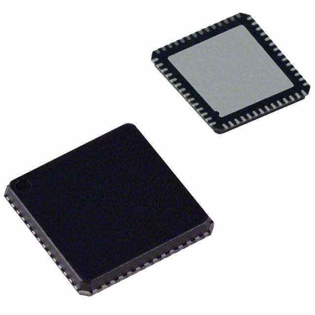
| 产品图片 |
|
| 产品型号 | LTC4213IDDB#TRMPBF |
| rohs | 无铅 / 符合限制有害物质指令(RoHS)规范要求 |
| 产品系列 | * |
| 供应商器件封装 | 8-DFN(3x2) |
| 其它名称 | LTC4213IDDB#TRMPBFDKR |
| 包装 | Digi-Reel® |
| 安装类型 | 表面贴装 |
| 封装/外壳 | 8-WFDFN 裸露焊盘 |
| 应用 | * |
| 标准包装 | 1 |
| 类型 | * |
| 配用 | /product-detail/zh/DC872A/DC872A-ND/4496878 |


- 商务部:美国ITC正式对集成电路等产品启动337调查
- 曝三星4nm工艺存在良率问题 高通将骁龙8 Gen1或转产台积电
- 太阳诱电将投资9.5亿元在常州建新厂生产MLCC 预计2023年完工
- 英特尔发布欧洲新工厂建设计划 深化IDM 2.0 战略
- 台积电先进制程称霸业界 有大客户加持明年业绩稳了
- 达到5530亿美元!SIA预计今年全球半导体销售额将创下新高
- 英特尔拟将自动驾驶子公司Mobileye上市 估值或超500亿美元
- 三星加码芯片和SET,合并消费电子和移动部门,撤换高东真等 CEO
- 三星电子宣布重大人事变动 还合并消费电子和移动部门
- 海关总署:前11个月进口集成电路产品价值2.52万亿元 增长14.8%


PDF Datasheet 数据手册内容提取
LTC4213 No R ™ SENSE Electronic Circuit Breaker FEATURES DESCRIPTIOU ■ Fast 1(cid:181)s Response Circuit Breaker The LTC®4213 is an Electronic Circuit Breaker. An over- ■ 3 Selectable Circuit Breaker Thresholds current circuit breaker senses the voltage across the drain ■ No Sense Resistor Required and source terminals of an external N-channel MOSFET ■ Dual Level Overcurrent Fault Protection with no need for a sense resistor. The advantages are a ■ Controls Load Voltages from 0V to 6V lower cost and reduced voltage and power loss in the ■ High Side Drive for External N-Channel FET switch path. An internal high-side driver controls the ■ Undervoltage Lockout external MOSFET gate. ■ READY Pin Signals When Circuit Breaker Armed Two integrated comparators provide dual level over- ■ Small Plastic (3mm x 2mm) DFN Package current protection over the bias supply to ground common mode range. The slow comparator has 16(cid:181)s response APPLICATIOUS while the fast comparator trips in 1(cid:181)s. The circuit breaker has three selectable trip thresholds: 25mV, 50mV and ■ Electronic Circuit Breaker 100mV. An ON pin controls the ON/OFF and resets circuit ■ High-Side Switch breaker faults. READY signals the MOSFET is conducting ■ Hot Board Insertion and the circuit breaker is armed. The LTC4213 operates from V = 2.3V to 6V. CC , LTC and LT are registered trademarks of Linear Technology Corporation. No RSENSE is a trademark of Linear Technology Corporation. All other trademarks are the property of their respective owners. TYPICAL APPLICATIOU 1.25V Electronic Circuit Breaker Severe Overload Response SI4864DY VIN VOUT 1.25V 1.25V 3.5A IOUT (50A/DIV) 2.3V TVOB I6AVS VCC SENSEP GATE SENSEN VBIAS VOUT LTC4213 10k (1V/DIV) OFF ON ON GND ISEL READY VGATE (5V/DIV) 4213 TA01 VIN (1V/DIV) 2(cid:181)s/DIV 4213 TA01b 4213f 1
LTC4213 ABSOLUTE WAXIWUW RATIUGS PACKAGE/ORDER IUFORWATIOU (Note 1) ORDER PART Bias Supply Voltage (V ) ...........................–0.3V to 9V TOP VIEW CC NUMBER Input Voltages ON, SENSEP, SENSEN.............................–0.3V to 9V READY 1 8 VCC LTC4213CDDB ON 2 7 SENSEP I ..........................................–0.3V to (V + 0.3V) 9 LTC4213IDDB SEL CC ISEL 3 6 SENSEN Output Voltages GND 4 5 GATE GATE .....................................................–0.3V to 15V DDB PART* READY.....................................................–0.3V to 9V DDB PACKAGE MARKING 8-LEAD (3mm (cid:215) 2mm) PLASTIC DFN Operating Temperature Range TJMAX = 125(cid:176)C, θJA = 250(cid:176)C/W LBHV LTC4213C ...............................................0(cid:176)C to 70(cid:176)C EXPOSED PAD (PIN 9) PCB CONNECTION OPTIONAL LTC4213I.............................................–40(cid:176)C to 85(cid:176)C Storage Temperature Range................. –65(cid:176)C to 150(cid:176)C Consult LTC Marketing for parts specified with wider operating temperature ranges. Lead Temperature (Soldering, 10sec)...................300(cid:176)C *The temperature grade is identified by a label on the shipping container. ELECTRICAL CHARACTERISTICS The ● denotes the specifications which apply over the full operating temperature range, otherwise specifications are at TA = 25(cid:176)C. VCC = 5V, ISEL = 0 unless otherwise noted. (Note 2) SYMBOL PARAMETER CONDITIONS MIN TYP MAX UNITS V Bias Supply Voltage ● 2.3 6 V CC V SENSEP Voltage ● 0 6 V SENSEP I V Supply Current ● 1.6 3 mA CC CC V V Undervoltage Lockout Release V Rising ● 1.8 2.07 2.23 V CC(UVLR) CC CC ∆VCC(UVHYST) VCC Undervoltage Lockout Hysteresis ● 30 100 160 mV ISENSEP SENSEP Input Current VSENSEP = VSENSEN = 5V, Normal Mode 15 40 80 (cid:181)A VSENSEP = VSENSEN = 0, Normal Mode –1 –15 (cid:181)A ISENSEN SENSEN Input Current VSENSEP = VSENSEN = 5V, Normal Mode 15 40 80 (cid:181)A VSENSEP = VSENSEN = 0, Normal Mode –1 –15 (cid:181)A VSENSEP = VSENSEN = 5V, 50 280 (cid:181)A Reset Mode or Fault Mode V Circuit Breaker Trip Voltage I = 0, V = V ● 22.5 25 27.5 mV CB SEL SENSEP CC V = V – V I = Floated, V = V ● 45 50 55 mV CB SENSEP SENSEN SEL SENSEP CC I = V V = V ● 90 100 110 mV SEL CC, SENSEP CC V Fast Circuit Breaker Trip Voltage I = 0, V = V ● 63 100 115 mV CB(FAST) SEL SENSEP CC V = V – V I = Floated, V = V ● 126 175 200 mV CB(FAST) SENSEP SENSEN SEL SENSEP CC I = V V = V ● 252 325 371 mV SEL CC, SENSEP CC IGATE(UP) GATE Pin Pull Up Current VGATE = 0V ● –50 –100 –150 (cid:181)A IGATE(DN) GATE Pin Pull Down Current ∆VSENSEP – VSENSEN = 200mV, VGATE = 8V ● 10 40 mA ∆VGSMAX External N-Channel Gate Drive VSENSEN = 0, VCC ≥ 2.97V, IGATE = –1(cid:181)A ● 4.8 6.5 8 V VSENSEN = 0, VCC = 2.3V, IGATE = –1(cid:181)A ● 2.65 4.3 8 V ∆VGSARM VGS Voltage to Arm Circuit Breaker VSENSEN = 0, VCC ≥ 2.97V ● 4.4 5.4 7.6 V V = 0, V = 2.3V ● 2.5 3.5 7 V SENSEN CC 4213f 2
LTC4213 ELECTRICAL CHARACTERISTICS The ● denotes the specifications which apply over the full operating temperature range, otherwise specifications are at TA = 25(cid:176)C. VCC = 5V, ISEL = 0 unless otherwise noted. (Note 2) SYMBOL PARAMETER CONDITIONS MIN TYP MAX UNITS ∆VGSMAX – ∆VGSARM Difference Between ∆VGSMAX and VSENSEN = 0, VCC ≥ 2.97V ● 0.3 1.1 V ∆VGSARM VSENSEN = 0, VCC = 2.3V ● 0.15 0.8 V V READY Pin Output Low Voltage I = 1.6mA, Pull Down Device On ● 0.2 0.4 V READY(OL) READY IREADY(LEAK) READY Pin Leakage Current VREADY = 5V, Pull Down Device Off ● 0 –1 (cid:181)A V ON Pin High Threshold ON Rising, GATE Pulls Up ● 0.76 0.8 0.84 V ON(TH) ∆VON(HYST) ON Pin Hysteresis ON Falling, GATE Pulls Down 10 40 90 mV V ON Pin Reset Threshold ON Falling, Fault Reset, GATE Pull Down ● 0.36 0.4 0.44 V ON(RST) ION(IN) ON Pin Input Current VON = 1.2V ● 0 –1 (cid:181)A ∆VOV Overvoltage Threshold ● 0.41 0.7 1.1 V ∆VOV = VSENSEP – VCC tOV Overvoltage Protection Trip Time VSENSEP = VSENSEN = Step 5V to 6.2V 25 65 160 (cid:181)s tFAULT(SLOW) VCB Trips to GATE Discharging ∆VSENSE Step 0mV to 50mV, ● 7 16 27 (cid:181)s V Falling, V = V = 5V SENSEN CC SENSEP tFAULT(FAST) VCB(FAST) Trips to GATE Discharging ∆VSENSE Step 0V to 0.3V, VSENSEN Falling, ● 1 2.5 (cid:181)s V = 5V SENSEP tDEBOUNCE Startup De-Bounce Time VON = 0V to 2V Step to Gate Rising, 27 60 130 (cid:181)s (Exiting Reset Mode) tREADY READY Delay Time VGATE = 0V to 8V Step to READY Rising, 22 50 115 (cid:181)s V = V = 0 SENSEP SENSEN tOFF Turn-Off Time VON = 2V to 0.6V Step to GATE Discharging 1.5 5 10 (cid:181)s tON Turn-On Time VON = 0.6V to 2V Step to GATE Rising, 4 8 16 (cid:181)s (Normal Mode) tRESET Reset Time VON Step 2V to 0V 20 80 150 (cid:181)s Note 1: Absolute Maximum Ratings are those values beyond which the life Note 2: All currents into device pins are positive; all currents out of device of a device may be impaired. pins are negative. All voltages are referenced to ground unless otherwise specified. 4213f 3
LTC4213 TYPICAL PERFORW AU CE CHARACTERISTICS Specifications are at TA = 25(cid:176)C. VCC = 5V unless otherwise noted. I vs V I vs Temperature V vs Temperature CC CC CC CC(UVLR) 3.0 3.0 2.3 V) D ( A) 2.5 A) 2.5 HOL 2.2 m m S CURRENT ( 12..50 CURRENT ( 12..50 KOUT THRE 22..01 VCC RISING PPLY PPLY E LOC VCC FALLING U 1.0 U 1.0 G 1.9 S S A BIAS 0.5 BIAS 0.5 RVOLT 1.8 E D N U 0 0 1.7 2.0 2.5 3.0 3.5 4.0 4.5 5.0 5.5 6.0 –50 –25 0 25 50 75 100 125 –50 –25 0 25 50 75 100 125 BIAS SUPPLY VOLTAGE (V) TEMPERATURE ((cid:176)C) TEMPERATURE ((cid:176)C) 4213 G01 4213 G02 4213 G03 Normalized V vs V Normalized V vs Temperature Normalized V vs V CB CC CB CB(FAST) CC 1.06 1.06 1.06 1.04 1.04 1.04 ST) MALIZED VCB11..0002 MALIZED VCB11..0002 LIZED VCB(FA11..0002 NOR 0.98 NOR 0.98 RMA 0.98 O N 0.96 0.96 0.96 0.94 0.94 0.94 2.0 2.5 3.0 3.5 4.0 4.5 5.0 5.5 6.0 –50 –25 0 25 50 75 100 125 2.0 2.5 3.0 3.5 4.0 4.5 5.0 5.5 6.0 BIAS SUPPLY VOLTAGE (V) TEMPERATURE ((cid:176)C) BIAS SUPPLY VOLTAGE (V) 4213 G04 4213 G05 4213 G06 Normalized V vs CB(FAST) Temperature I vs V I vs Temperature GATE(UP) CC GATE(UP) 1.06 104 104 1.04 ST) 102 102 B(FA1.02 A) A) ALIZED VC1.00 ((cid:181)ATE(UP)100 ((cid:181)ATE(UP)100 M G G R 0.98 I I O N 98 98 0.96 0.94 96 96 –50 –25 0 25 50 75 100 125 2.0 2.5 3.0 3.5 4.0 4.5 5.0 5.5 6.0 –50 –25 0 25 50 75 100 125 TEMPERATURE ((cid:176)C) BIAS SUPPLY VOLTAGE (V) TEMPERATURE ((cid:176)C) 4213 G07 4213 G08 4213 G09 4213f 4
LTC4213 TYPICAL PERFORW AU CE CHARACTERISTICS Specifications are at TA = 25(cid:176)C. VCC = 5V unless otherwise noted. ∆VGSMAX and ∆VGSARM vs ∆VGSMAX and ∆VGSARM vs VCC Temperature VON(TH) vs VCC 8 8 0.90 ∆VGSMAX ∆VGSMAX (FOR 5VCC) D V (V)∆GSARM 76 ∆VGSARM D V (V)∆GSARM 76 ∆VGSARM (FOR 5VCC) RESHOLD (V) 00..8805 LHOIWGH T THHRREESSHHOOLLDD ANX 5 ANX 5 ∆VGSMAX (FOR 2.5VCC) N TH 0.75 MA MA PI VGS VGS ∆VGSARM (FOR 2.5VCC) ON ∆ 4 ∆ 4 0.70 3 3 0.65 2.0 2.5 3.0 3.5 4.0 4.5 5.0 5.5 6.0 –50 –25 0 25 50 75 100 125 2.0 2.5 3.0 3.5 4.0 4.5 5.0 5.5 6.0 BIAS SUPPLY VOLTAGE (V) TEMPERATURE ((cid:176)C) BIAS SUPPLY VOLTAGE (V) 4213 G10 4213 G11 4213 G12 VON(TH) vs Temperature ∆VOV vs VCC ∆VOV vs Temperature 0.90 0.74 1.0 V) 0.85 LD (V) 0.72 LD (V) 0.9 OLD ( 0.80 HIGH THRESHOLD ESHO ESHO 0.8 H R R S H H N THRE 0.75 LOW THRESHOLD TAGE T 0.70 TAGE T 0.7 N PI VOL VOL 0.6 O R 0.68 R E E 0.70 V V O O 0.5 0.65 0.66 0.4 –50 –25 0 25 50 75 100 125 2.0 2.5 3.0 3.5 4.0 4.5 5.0 5.5 6.0 –50 –25 0 25 50 75 100 125 TEMPERATURE ((cid:176)C) BIAS SUPPLY VOLTAGE (V) TEMPERATURE ((cid:176)C) 4213 G13 4213 G14 4213 G15 t and t vs DEBOUNCE READY t and t vs V Temperature t vs V DEBOUNCE READY CC RESET CC 100 100 120 100 s) 80 s) 80 (cid:181) (cid:181) AND t (NCEREADY4600 tDtERBEOAUDNYCE AND t (NCEREADY4600 tDtERBEOAUDNYCE t (s)(cid:181)RESET 8600 U U 40 O O B B DE DE t 20 t 20 20 0 0 0 2.0 2.5 3.0 3.5 4.0 4.5 5.0 5.5 6.0 –50 –25 0 25 50 75 100 125 2.0 2.5 3.0 3.5 4.0 4.5 5.0 5.5 6.0 BIAS SUPPLY VOLTAGE (V) TEMPERATURE ((cid:176)C) BIAS SUPPLY VOLTAGE (V) 4213 G16 4213 G17 4213 G18 4213f 5
LTC4213 TYPICAL PERFORW AU CE CHARACTERISTICS Specifications are at TA = 25(cid:176)C. VCC = 5V unless otherwise noted. t vs Temperature t vs V t vs Temperature RESET FAULT(SLOW) CC FAULT(SLOW) 100 22 22 20 20 90 s) 18 s) 18 (cid:181) (cid:181) s)(cid:181) (W) (W) t (RESET 80 ULT(SLO 16 ULT(SLO 16 tFA 14 tFA 14 70 12 12 60 10 10 –50 –25 0 25 50 75 100 125 2.0 2.5 3.0 3.5 4.0 4.5 5.0 5.5 6.0 –50 –25 0 25 50 75 100 125 TEMPERATURE ((cid:176)C) BIAS SUPPLY VOLTAGE (V) TEMPERATURE ((cid:176)C) 4213 G19 4213 G20 4213 G21 t vs V t vs Temperature FAULT(FAST) CC FAULT(FAST) 1.3 1.3 1.2 1.2 s) 1.1 s) 1.1 (cid:181) (cid:181) (AST) 1.0 (AST) 1.0 ULT(F ULT(F A A tF 0.9 tF 0.9 0.8 0.8 0.7 0.7 2.0 2.5 3.0 3.5 4.0 4.5 5.0 5.5 6.0 –50 –25 0 25 50 75 100 125 BIAS SUPPLY VOLTAGE (V) TEMPERATURE ((cid:176)C) 4213 G22 4213 G23 4213f 6
LTC4213 PIU FUUCTIOUS READY (Pin 1): READY Status Output. Open drain output voltage between the GATE and SENSEN pins to a safe gate that goes high impedance when the external MOSFET is on drive voltage of less than 8V. When the circuit breaker and the circuit breaker is armed. Otherwise this pin pulls trips, the GATE pin abruptly pulls to GND. low. SENSEN (Pin 6): Circuit Breaker Negative Sense Input. ON (Pin 2): ON Control Input. The LTC4213 is in reset Connect this pin to the source of the external MOSFET. mode when the ON pin is below 0.4V. When the ON pin During reset or fault mode, the SENSEN pin discharges the increases above 0.8V, the device starts up and the GATE output to ground with 280(cid:181)A. pulls up with a 100(cid:181)A current source. When the ON pin SENSEP (Pin 7): Circuit Breaker Positive Sense Input. drops below 0.76V, the GATE pulls down. To reset a circuit Connect this pin to the drain of external N-channel MOSFET. breaker fault, the ON pin must go below 0.4V. The circuit breaker trips when the voltage across SENSEP I (Pin 3): Threshold Select Input. With the I pin and SENSEN exceeds V . The input common mode range SEL SEL CB grounded, float or tied to V the V is set to 25mV, 50mV of the circuit breaker is from ground to V + 0.2V when CC CB CC or 100mV, respectively. The corresponding V V < 2.5V. For V ≥ 2.5V, the input common mode range CB(FAST) CC CC values are 100mV, 175mV and 325mV. is from ground to V + 0.4V. CC GND(Pin 4): Device Ground. V (Pin 8): Bias Supply Voltage Input. Normal operation CC is between 2.3V and 6V. An internal under-voltage lockout GATE (Pin 5): GATE Drive Output. An internal charge circuit disables the device when V < 2.07V. pump supplies 100(cid:181)A pull-up current to the gate of the CC external N-channel MOSFET. Internal circuitry limits the Exposed Pad (Pin 9): Exposed pad may be left open or connected to device ground. 4213f 7
LTC4213 BLOCK DIAGRAW SENSEP SENSEN VCC 7 6 8 ISEL VCB VCB(FAST) +VCB VCB(FAST) + +0.7V 3 100mV 325mV – – – VCC 50mV 175mV 25mV 100mV + – + – + – VCC SLOWCOMP FASTCOMP OVCOMP CHARGE 280(cid:181)A PUMP 16(cid:181)s 1(cid:181)s 65(cid:181)s READY DELAY DELAY RESET OR DELAY 100(cid:181)A 1 CB TRIPS CB TRIPS FAULT MODE BLANK OV TRIPS GATE ON GATE 5 50(cid:181)s LOGIC 6.5V DELAY + CLAMP ARM ARM CIRCUIT COMP RESET STARTUP NORMAL MODE – +– GATE ON/OFF VGSARM SENSEN 80(cid:181)s 60(cid:181)s 8(cid:181)s 5(cid:181)s GATEOFF DELAY DELAY DELAY COMP1 UV COMP COMP2 – + + – + – 0.4V VCC 2.07V 0.8V 2 4 ON GND 4213 BD 4213f 8
LTC4213 TIWIUG DIAGRAW 1 2 3 4 5 6 VON(TH) VON(TH) VON(TH) – VON(HYST) VON VGSMAX VGSMAX – 0.3V VGATE 0.3V 0.3V tDEBOUNCE tOFF tON 1 2 3 4 5 1.2V ∆VSENSE VGATE VGSMAX VGSMAX – 0.3V 0.3V VON VON(TH) VON(RST) 4213 TD tFAULT(FAST) tRESET 4213f 9
LTC4213 OPERATIOU Overview thresholds of SLOWCOMP and FASTCOMP are V and CB V . The I pin selects one of the three settings: The LTC4213 is an Electronic Circuit Breaker (ECB) that CB(FAST) SEL senses load current with the the R of the external 1. V = 25mV and V = 100mV with I at GND DSON CB CB(FAST) SEL MOSFET instead of using an external sense resistor. This 2. V = 50mV and V = 175mV with I floating CB CB(FAST) SEL no R method is less precise than R method due SENSE SENSE to the variation of RDSON. However, the advantages are 3. VCB = 100mV and VCB(FAST) = 325mV with ISEL at VCC less complex, lower cost and reduce voltage and power I can be stepped dynamically, such as to allow a higher SEL loss in the switch path owing to the absence of a sense circuit breaker threshold at startup and a lower threshold resistor. Without the external sense resistor voltage drop, after supply current has settled. The inputs of the com- the V improvement can be quite significant especially OUT parators are SENSEP and SENSEN pins. The voltage in the low voltage applications. The LTC4213 is designed across the drain and source of the external MOSFET is to operate over a bias supply range from 2.3V to 6V. When sensed at SENSEP and SENSEN. bias supply voltage and the ON pin are sufficiently high, the GATE pin starts charging after an internal debounce delay ∆V = V −V (1) SENSE SENSEP SENSEN of 60(cid:181)s. During the GATE ramp-up, the circuit breaker is When ∆V exceeds the V threshold but is less than SENSE CB not armed until the external MOSFET is fully turned on. V , the comparator SLOWCOMP trips the circuit CB(FAST) Once the circuit breaker is armed, the LTC4213 monitors breaker after a 16(cid:181)s delay. If ∆V is greater than SENSE the load current through the R of the external MOSFET. DSON V , the comparator FASTCOMP trips the circuit CB(FAST) breaker in 1(cid:181)s. Circuit Breaker Function A severe short circuit condition can cause the load supply The LTC4213 provides dual level and dual response time to dip substantially. This does not pose a problem for the circuit breaker functions for overcurrent protection. LTC4213 as the input stages of the current limit compara- The LTC4213 circuit breaker function block consists of tors are common mode to ground. two comparators, SLOWCOMP and FASTCOMP. The APPLICATIOUS IUFORWATIOU Figure 1 shows an electronic circuit breaker (ECB) appli- sense the load current at the drain and source of the cation. An external auxiliary supply biases the V pin and external MOSFET. In ECB applications, large input bypass CC the internal circuitry. A V load supply powers the load via capacitors are usually recommended for good transient IN an external MOSFET. The SENSEP and SENSEN pins performance. Q1 Undervoltage Lockout SI4864DY VIN VOUT 1.25V 1.25V + + An internal undervoltage lockout (UVLO) circuit resets the CIN CLOAD 3.5A 100(cid:181)F 100(cid:181)F LTC4213 if the V supply is too low for normal operation. CC The UVLO comparator (UVCOMP) has a low-to-high thresh- V2B.I5AVS C1 VCC SENSEP GATE SENSEN VCC old of 2.07V and 100mV of hysteresis. UVLO shares the 0.1(cid:181)F LTC4213 R4 glitch filters for both low-to-high transition (startup) and 10k high-to-low transition (reset) with the ON pin compara- OFF ON ON GND ISEL READY tors. Above 2.07V bias supply voltage, the LTC4213 starts if the ON pin conditions are met. Short, shallow bus bias 4213 F01 Figure 1. LTC4213 Electronic Circuit Breaker Application 4213f 10
LTC4213 APPLICATIOUS IUFORWATIOU supply transient dips below 1.97V of less than 80(cid:181)s are ∆V and V GSARM GSMAX ignored. Each MOSFET has a recommended V drive voltage GS where the channel is deemed fully enhanced and R is ON Function DSON minimized. Driving beyond this recommended V volt- GS When VON is below comparator COMP1’s threshold of age yields a marginal decrease in RDSON. At startup, the 0.4V for 80(cid:181)s, the device resets. The system leaves reset gate voltage starts at ground potential. The GATE ramps mode if the ON pin rises above comparator COMP2’s past the MOSFET threshold and the load current begins to threshold of 0.8V and the UVLO condition is met. Leaving flow. When V exceeds ∆V , the circuit breaker is GS GSARM reset mode, the GATE pin starts up after a tDEBOUNCE delay armed and enabled. The chosen MOSFET should have a of 60(cid:181)s. When ON goes below 0.76V, the GATE shuts off recommended minimum V drive level that is lower than GS after a 5(cid:181)s glitch filter delay. The output is discharged by ∆V . Finally, V reaches a maximum at ∆V GSARM GS GSMAX. the external load when V is in between 0.4V to 0.8V. At ON this state, the ON pin can re-enable the GATE if V Trip and Reset Circuit Breaker ON exceeds 0.8V for more than 8(cid:181)s. Alternatively, the device Figure2 shows the timing diagram of V and V GATE READY resets if the ON pin is brought below 0.4V for 80(cid:181)s. Once after a fault condition. A tripped circuit breaker can be reset reset, the GATE pin restarts only after the t 60(cid:181)s DEBOUNCE either by cycling the V bias supply below UVLO thresh- CC delay at V rising above 0.8V. To protect the ON pin from ON old or pulling ON below 0.4V for >t . Figure3 shows RESET overvoltage stress due to supply transients, a series the timing diagram for a tripped circuit breaker being reset resistor of greater than 10k is recommended when the ON by the ON pin. pin is connected directly to the supply. An external resis- tive divider at the ON pin can be used with COMP2 to set Calculating Current Limit a supply undervoltage lockout value higher than the inter- The fault current limit is determined by the R of the nal UVLO circuit. An RC filter can be implemented at the DSON MOSFET and the circuit breaker voltage V . ON pin to increase the powerup delay time beyond the CB internal 60(cid:181)s delay. V CB I = (2) LIMIT Gate Function RDSON The GATE pin is held low in reset mode. 60(cid:181)s after leaving The R value depends on the manufacturer’s distribu- DSON reset mode, the GATE pin is charged up by an internal tion, V and junction temperature. Short Kelvin-sense GS 100(cid:181)A current source. The circuit breaker arms when connections between the MOSFET drain and source to V > V + ∆V . In normal mode operation, the LTC4213 SENSEP and SENSEN pins are strongly GATE SENSEN GSARM the GATE peak voltage is internally clamped to ∆V recommended. GSMAX above the SENSEN pin. When the circuit breaker trips, an For a selected MOSFET, the nominal load limit current is internal MOSFET shorts the GATE pin to GND, turning off given by: the external MOSFET. V CB(NOM) READY Status I = (3) LIMIT(NOM) R DSON(NOM) The READY pin is held low during reset and at startup. It is pulled high by an external pullup resistor 50(cid:181)s after the The minimum load limit current is given by: circuit breaker arms. The READY pin pulls low if the circuit V breaker trips or the ON pin is pulled below 0.76V, or V CB(MIN) CC I = (4) LIMIT(MIN) drops below undervoltage lockout. R DSON(MAX) 4213f 11
LTC4213 APPLICATIOUS IUFORWATIOU The maximum load limit current is given by: Example Current Limit Calculation An Si4410DY is used for current detection in a 5V supply V CB(MAX) I = (5) system with the LTC4213 V at 25mV (I pin grounded). LIMIT(MAX) CB SEL R DSON(MIN) The R distribution for the Si4410DY is DSON Most MOSFET data sheets have an R specification DSON Typical R = 0.015Ω = 100% with typical and maximum values but no minimum value. DSON Assuming a normal distribution with typical as mean, the Maximum R = 0.02Ω = 133.3% DSON minimum value can be estimated as Estimated MIN R = 2 • 15 – 20 = 0.010Ω = 66.7% DSON RDSON(MIN) =2(cid:149)RDSON(NOM)−RDSON(MAX) (6) The RDSON variation due to gate drive is The LTC4213 gives higher gate drive than the manufac- R @ 4.5V = 0.015Ω = 100% (spec. TYP) DSON GS turer specified gate drive for R . This gives a slightly DSON R @ 4.8V = 0.014Ω = 93% (MIN ∆V ) DSON GS GSMAX lower R than specified. Operating temperature also DSON modulates the RDSON value. RDSON @ 7VGS = 0.0123Ω = 82% (NOM ∆VGSMAX) R @ 8V = 0.012Ω = 80% (MAX ∆V ) DSON GS GSMAX CIRCUIT BREAKER TRIPS SHORT CIRCUIT GATE AND READY PINS PULL LOW A B >VCB VCB ∆VSENSE CB TRIPS VGATE VREADY tFAULT 4213 F02 Figure 2. Short Circuit Fault Timing Diagram 4213f 12
LTC4213 APPLICATIOUS IUFORWATIOU CIRCUIT BREAKER TRIPS GATE AND READY PINS PULL LOW SHORT CIRCUIT NOT RESET RESET REINITIALIZE RESTART 1 2 3 4 5 67 8 VCC > 2.07V VON 0.8V 0.76V 0.4V 0V >VCB VCB ∆VSENSE tFAULT CB TRIPS VGATE VREADY VON < 0.4V DURATION > tRESET tDEBOUNCE NORMAL MODE FAULT LATCHED OFF STARTUP CYCLE 4213 F03 Figure 3. Resetting Fault Timing Diagram 4213f 13
LTC4213 APPLICATIOUS IUFORWATIOU Operating temperature of 0(cid:176) to 70(cid:176)C. Table 1. Nominal Operating ∆VGSMAX for Typical Bias Supply Voltage R @ 25(cid:176)C = 100% DSON VCC (V) ∆VGSMAX (V) RDSON @ 0(cid:176)C = 90% 2.3 4.3 2.5 5.0 R @ 70(cid:176)C = 120% DSON 2.7 5.6 MOSFET resistance variation: 3.0 6.5 R = 15m • 0.82 = 12.3mΩ 3.3 7.0 DSON(NOM) 5.0 7.0 R = 15m • 1.333 • 0.93 • 1.2 = 15m • 1.488 DSON(MAX) 6.0 7.0 = 22.3mΩ R = 15m • 0.667 • 0.80 • 0.90 = 15m • 0.480 DSON(MIN) Load Supply Power-Up after Circuit Breaker Armed = 7.2mΩ Figure4 shows a normal power-up sequence for the V variation: CB circuit in Figure 1 where the V load supply power-up after IN NOM V = 25mV = 100% circuit breaker is armed. V is first powered up by an CB CC auxiliary bias supply. V rises above 2.07V at time MIN V = 22.5mV = 90% CC CB point1. V exceeds 0.8V at time point 2. After a 60(cid:181)s ON MAX VCB = 27.5mV = 110% debounce delay, the GATE pin starts ramping up at time point3. The external MOSFET starts conducting at time The current limits are: point4. At time point5, V exceed ∆V and the GATE GSARM I = 25mV/12.3mΩ = 2.03A LIMIT(NOM) circuit breaker is armed. After 50(cid:181)s (t delay), READY READY I = 22.5mV/22.3mΩ = 1.01A pulls high by an external resistor at time point 6. READY LIMIT(MIN) signals the V load supply module to start its ramp. The I = 27.5mV/7.2mΩ = 3.82A IN LIMIT(MAX) load supply begins soft-start ramp at time point 7. The load For proper operation, the minimum current limit must supply ramp rate must be slow to prevent circuit breaker exceed the circuit maximum operating load current with tripping as in equation (8). margin. So this system is suitable for operating load current up to 1A. From this calculation, we can start with ∆VIN IOPMAX−ILOAD < (8) the general rule for MOSFET RDSON by assuming maxi- ∆t CLOAD mum operating load current is roughly half of the Where I is the maximum operating current defined I . Equation 7 shows the rule of thumb. OPMAX LIMIT(NOM) by equation 7. V I = CB(NOM) (7) For illustration, VCB = 25mV and RDSON = 3.5mΩ at the OPMAX 2•RDSON(NOM) nominal operating ∆VGSMAX. The maximum operating current is 3.5A (refer to equation 7). Assuming the load Note that the R is at the LTC4213 nominal DSON(NOM) can draw a current of 2A at power-up, there is a margin of operating ∆V rather than at typical vendor spec. GSMAX 1.5A available for C of 100(cid:181)F and V ramp rate should LOAD IN Table 1 gives the nominal operating ∆V at the GSMAX be <15V/ms. At time point 8, the current through the various operating V . From this table users can refer to CC MOSFET reduces after C is fully charged. LOAD the MOSFET’s data sheet to obtain the R value. DSON(NOM) 4213f 14
LTC4213 APPLICATIOUS IUFORWATIOU CIRCUIT BREAKER ARMS 1 2 3 4 5 6 7 8 2.07V 0.8V VCC, VON ∆VGSMAX + VSENSEN ∆VGSMAX ∆VGSARM VGATE Vth 100(cid:181)A VSENSEP, VSENSEN VREADY VCB ∆VSENSE RESET MODE tDEBOUNCE STARTUP CYCLE NORMAL CYCLE tREADY 4213 F04 Figure 4. Load Supply Power-Up After Circuit Breaker Armed 4213f 15
LTC4213 APPLICATIOUS IUFORWATIOU Load Supply Power-Up Before VCC At time point 7, the GATE voltage peaks. 50(cid:181)s after time point 6, READY goes HIGH. Referring back to Figure 1, the V load supply can also be IN powered up before V . Figure 5 shows the timing dia- CC Startup Problems gram with the V load supply active initially. An internal IN circuit ensures that the GATE pin is held low. At time point There is no current limit monitoring during output charg- 1, V clears UVLO and at time point 2, ON clears 0.8V. ing for the figure 5 power-up sequence where the load CC 60(cid:181)s later at time point 3, the GATE is ramped up with supply is powered up before VCC. This is because the GATE 100(cid:181)A. At time point 4, GATE reaches the external MOSFET voltage is below ∆VGSARM and the MOSFET may not reach threshold VTH and VOUT starts to ramp up. At time point 5, the specified RDSON. The VIN load supply should have V is near its peak. At time point 6, the circuit breaker sufficient capability to handle the inrush as the output SENSEN is armed and the circuit breaker can trip if ∆V > V . charges up. For proper startup, the final load at time SENSE CB CIRCUIT BREAKER ARMS VSENSEP – VSENSEN = VCB VGATE MAXES OUT READY SIGNALS 0 1 2 3 4 5 6 7 8 VCC > 2.07V VON > 0.8V VCC, VON ∆VGSMAX + VSENSEN ∆VGSARM + VSENSEN VGATE Vth VSENSEP VSENSEN VREADY tREADY RESET MODE tDEBOUNCE STARTUP CYCLE NORMAL CYCLE 4213 F05 Figure 5. Load Supply Power-Up Before V CC 4213f 16
LTC4213 APPLICATIOUS IUFORWATIOU point6 should be within the circuit breaker limits. Other- The selected MOSFET V absolute maximum rating should GS wise, the system fails to start and the circuit breaker trips meet the LTC4213 maximum ∆V of 8V. GSMAX immediately after arming. In most applications additional Other MOSFET criteria such as V , I , and R BDSS DMAX DSON external gate capacitance is not required unless C is LOAD should be reviewed. Spikes and ringing above maximum large and startup becomes problematic. If an external gate operating voltage should be considered when choosing capacitor is employed, its capacitance value should not be V . I should be greater than the current limit. The BDSS DMAX excessive unless it is used with a series resistor. This is maximum operating load current is determined by the because a big gate capacitor without resistor slows down R value. See the section on “Calculating Current DSON the GATE turn off during a fault. An alternative method Limit” for details. would be a stepped I pin to allow a higher current limit SEL during startup. Supply Requirements In the event of output short circuit or a severe overload, the The LTC4213 can be powered from a single supply or dual load supply can collapse during GATE ramp up due to load supply system. The load supply is connected to the supply current limit. The chosen MOSFET must withstand SENSEP pin and the drain of the external MOSFET. In the this possible brief short circuit condition before time single supply case, the V pin is connected to the load CC point6 where the circuit breaker is allowed to trip. Bench supply, preferably with an RC filter. With dual supplies, short circuit evaluation is a practical verification of a V is connected to an auxiliary bias supply V where CC AUX reliable design. To have current limit while powering a V voltage should be greater or equal to the load supply AUX MOSFET into short circuit conditions, it is preferred that voltage. The load supply voltage must be capable of the load supply sequences to turn on after the circuit sourcing more current than the circuit breaker limit. If the breaker is armed as described in an earlier section. load supply current limit is below the circuit breaker trip current, the LTC4213 may not react when the output Power-Off Cycle overloads. Furthermore, output overloads may trigger The system can be powered off by toggling the ON pin low. UVLO if the load supply has foldback current limit in a When ON is brought below 0.76V for 5(cid:181)s, the GATE and single supply system. READY pins are pulled low. The system resets when ON is brought below 0.4V for 80(cid:181)s. VIN Transient and Overvoltage Protection Input transient spikes are commonly observed whenever MOSFET Selection the LTC4213 responds to overload. These spikes can be The LTC4213 is designed to be used with logic (5V) and large in amplitude, especially given that large decoupling sub-logic (3V) MOSFETs for V potentials above 2.97V capacitors are absent in hot swap environments. These CC with ∆V exceeding 4.5V. For a V supply range short spikes can be clipped with a transient suppressor of GSMAX CC between 2.3V and 2.97V, sub-logic MOSFETs should be adequate voltage and power rating. In addition, the LTC4213 used as the minimum ∆V is less than 4.5V. can detect a prolonged overvoltage condition. When GSMAX 4213f 17
LTC4213 APPLICATIOUS IUFORWATIOU SENSEP exceeds V + 0.7V for more than 65(cid:181)s, the Typical Single Supply Hot Swap™ Application CC LTC4213’s internal overvoltage protection circuit acti- A typical single supply Hot Swap application is shown in vates and the GATE pin pulls down and turns off the Figure 7. The RESET signal at the backplane is held low external MOSFET. initially. When the PCB long edge makes contact the ON pin is held low (<0.4V) and the LTC4213 is kept in reset Typical Electronic Fuse Application for a Single mode. When the short edge makes contact the V load Supply System IN supply is connected to the card. The V is biased via the CC Figure 6 shows a single supply electronic fuse application. RC filter. The V is pre-charged via R5. To power-up OUT An RC filter at VCC pin filters out transient spikes. An successfully, the R5 resistor value should be small enough optional Schottky diode can be added if severe VCC dips to provide the load requirement and to overcome the during a fault start-up condition is a concern. The use of 280(cid:181)A current source sinking into the SENSEN pin. On the the Schottky and RC filter combination is allowed if the other hand, the R5 resistor value should be big enough load supply is above 2.9V and the total voltage drop avoiding big inrush current and preventing big short towards the VCC pin is less than 0.4V. The LTC4213’s circuit current. When RESET signals high at backplane, C2 internal UVLO filter further rejects bias supply’s transients capacitor at the ON pin charges up via the R3/R2 resistive of less than tRESET. During power-up, it is good engineer- divider. When ON pin voltage exceeds 0.8V, the GATE pin ing practice to ensure that VCC is fully established before begins to ramp up. When the GATE voltage peaks, the the ON pin enables the system at VON = 0.8V. In this external MOSFET is fully turned on and the VIN-to-VOUT application, the VCC voltage reached final value approxi- voltage drop reduces. In normal mode operation, the mately after a 5.3 • R1 C1 delay. This is followed by the ON LTC4213 monitors the load current through the RDSON of pin exceeding 0.8V after a 0.17 • R2C2 delay. The GATE pin the external MOSFET. starts up after an internal t delay. DEBOUNCE Hot Swap is a trademark of Linear Technology Corporation. Q1 SI4410DY VIN VOUT 5V 5V + D1 + CIN MBRO520L CLOAD 1A 100(cid:181)F 100(cid:181)F R1 33Ω 32R43k C1 VCC SENSEP GATE SENSEN VIN 10(cid:181)F LTC4213 R4 10k Q2 ON GND ISEL READY 2N7002 R2 C2 RESET 80.6k 0.22(cid:181)F 4213 F06 Figure 6. Single Supply Electronic Fuse 4213f 18
LTC4213 PACKAGE DESCRIPTIOU DDB Package 8-Lead Plastic DFN (3mm (cid:215) 2mm) (Reference LTC DWG # 05-08-1702) 0(.26 1S I–D0E.S0)5 3.00 –0.10 R = 0.T1Y1P5 0.38 – 0.10 (2 SIDES) 0.56 – 0.05 5 8 0.675 –0.05 (2 SIDES) 2.50 –0.05 2.00 –0.10 1.15 –0.05 PIN 1 BAR (2 SIDES) TOP MARK PIN 1 PACKAGE (SEE NOTE 6) CHAMFER OF OUTLINE 4 1 EXPOSED PAD 0.25 – 0.05 0.200 REF 0.75 –0.05 0.25 – 0.05 (DDB8) DFN 1103 0.50 BSC 0.50 BSC 2.20 –0.05 2.15 –0.05 (2 SIDES) (2 SIDES) 0 – 0.05 RECOMMENDED SOLDER PAD PITCH AND DIMENSIONS BOTTOM VIEW—EXPOSED PAD NOTE: 1. DRAWING CONFORMS TO VERSION (WECD-1) IN JEDEC PACKAGE OUTLINE M0-229 2.DRAWING NOT TO SCALE 3.ALL DIMENSIONS ARE IN MILLIMETERS 4. DIMENSIONS OF EXPOSED PAD ON BOTTOM OF PACKAGE DO NOT INCLUDE MOLD FLASH. MOLD FLASH, IF PRESENT, SHALL NOT EXCEED 0.15mm ON ANY SIDE 5. EXPOSED PAD SHALL BE SOLDER PLATED 6.SHADED AREA IS ONLY A REFERENCE FOR PIN 1 LOCATION ON THE TOP AND BOTTOM OF PACKAGE 4213f Information furnished by Linear Technology Corporation is believed to be accurate and reliable. 19 However, no responsibility is assumed for its use. Linear Technology Corporation makes no represen- tation that the interconnection of its circuits as described herein will not infringe on existing patent rights.
LTC4213 TYPICAL APPLICATIOU STAGGERED VIN PCB EDGE CONNECTOR Q1 R5 IRF7455 330Ω VIN VOUT 3.3V 3.3V Zx R3 3.6A SMAJ6.0A 182k + CLOAD 100(cid:181)F D1 BAT54ALT1 SENSEP GATE SENSEN RESET ON R1 R2 C2 68Ω 80.6k 1(cid:181)F LTC4213 R4 10k VCC READY C1 2.2(cid:181)F ISEL GND NC 4213 TA02 BACKPLANE GND CARD GND Figure 7. Single Supply Hot Board Insertion RELATED PARTS PART NUMBER DESCRIPTION COMMENTS LTC1421 Dual Channel, Hot Swap™ Controller 24-Pin, Operates from 3V to 12V and Supports –12V LTC1422 Single Channel, Hot Swap Controller in SO-8 Operates from 2.7V to 12V, System Reset Output LTC1642 Fault Protected, Hot Swap Controller Operates up to 16.5V, Overvoltage Protection to 33V LTC1643AL/LTC1643AH PCI Hot Swap Controllers 3.3V, 5V and –12V Supplies LTC1645 Dual Channel Hot Swap Controller Operates from 1.2V to 12V, Power Sequencing LTC1647 Dual Channel, Hot Swap Controller Operates from 2.7V to 16.5V LTC4210 Single Channel, Hot Swap Controller in SOT-23 Operates from 2.7V to 16.5V, Multifunction Current Control LTC4211 Single Channel, Hot Swap Controller in MSOP 2.5V to 16.5V, Multifunction Current Control LTC4216 Ultra Low Voltage Hot Swap Controller Operates from 2.7V to 16.5V, Multifunction Current LTC4221 Dual Channel, Hot Swap Controller Protects Load Voltages from 0V to 6V LTC4230 Triple Channel, Hot Swap Controller 1.7V to 16.5V, Multifunction Current Control LTC4251 –48V Hot Swap Controller in S0T-23 –48V Hot Swap Controller, Active Current Limiting LTC4252 –48V Hot Swap Controller in MSOP Active Current Limiting with Drain Acceleration LTC4253 –48V Hot Swap Controller and Sequencer Active Current Limiting with Drain Acceleration and Three Sequenced Power Good Outputs 4213f 20 Linear Technology Corporation LT/TP 0405 500 (cid:149) PRINTED IN USA 1630 McCarthy Blvd., Milpitas, CA 95035-7417 (408) 432-1900 ● FAX: (408) 434-0507 ● www.linear.com ' LINEAR TECHNOLOGY CORPORATION 2005