 Datasheet下载
- 型号: HFBR-RUS500Z
- 制造商: Avago Technologies
- 库位|库存: xxxx|xxxx
- 要求:
| 数量阶梯 | 香港交货 | 国内含税 |
| +xxxx | $xxxx | ¥xxxx |
查看当月历史价格
查看今年历史价格
HFBR-RUS500Z产品简介:
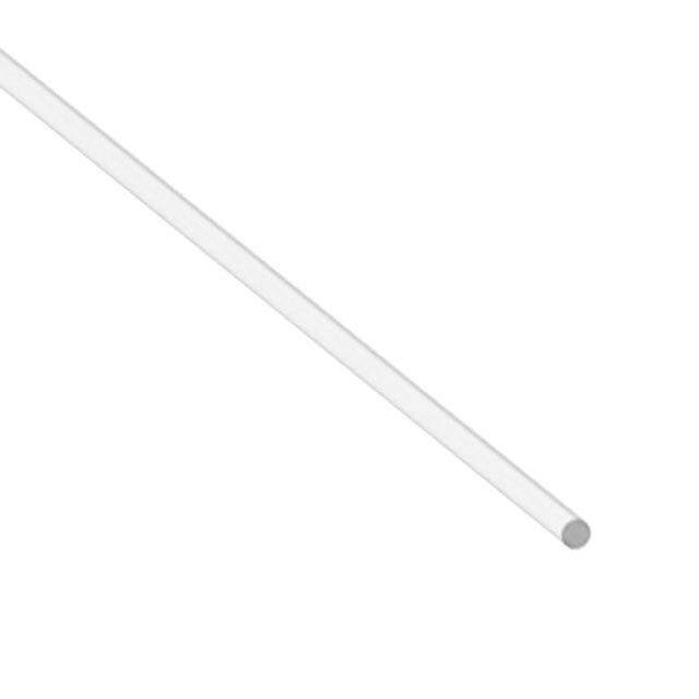
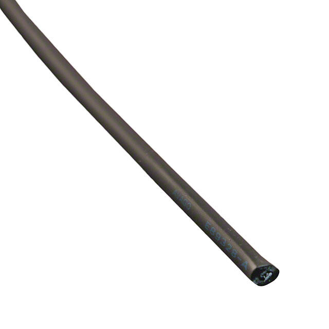
ICGOO电子元器件商城为您提供HFBR-RUS500Z由Avago Technologies设计生产,在icgoo商城现货销售,并且可以通过原厂、代理商等渠道进行代购。 HFBR-RUS500Z价格参考¥3077.15-¥3320.69。Avago TechnologiesHFBR-RUS500Z封装/规格:光纤电缆, FIBER OPTIC CBL SIMPLEX 1=500M。您可以下载HFBR-RUS500Z参考资料、Datasheet数据手册功能说明书,资料中有HFBR-RUS500Z 详细功能的应用电路图电压和使用方法及教程。
Broadcom Limited旗下的型号为HFBR-RUS500Z的光纤电缆,属于高性能光纤通信产品,广泛应用于工业自动化、通信设备、测试仪器及医疗设备等领域。该产品采用可靠的光通信技术,具备高速传输和抗电磁干扰的特性,适合在复杂电磁环境中稳定工作。在工业控制中,可用于PLC、传感器和执行器之间的数据连接;在通信设备中,适用于交换机、路由器等设备之间的高速信号传输;在医疗设备中,保障了数据的稳定传输与设备的安全运行。此外,其坚固的设计也适用于恶劣工业环境,如工厂生产线、能源设施等。总体而言,HFBR-RUS500Z凭借其高可靠性、高速率和广泛的环境适应性,在多种高要求场景中发挥着重要作用。
| 参数 | 数值 |
| 产品目录 | |
| 描述 | FIBER OPTIC CBL SIMPLEX 1=500M光纤线缆 BLK PLAST CABLE SMPL X 500 MTRSRoHS |
| 产品分类 | |
| 品牌 | Avago Technologies |
| 产品手册 | |
| 产品图片 |
|
| rohs | 符合RoHS无铅 / 符合限制有害物质指令(RoHS)规范要求 |
| 产品系列 | 光纤线缆,Avago Technologies HFBR-RUS500ZHFBR |
| 数据手册 | http://www.avagotech.com/docs/AV02-1508EN |
| 产品型号 | HFBR-RUS500Z |
| 产品目录页面 | |
| 产品种类 | 光纤线缆 |
| 光纤类型 | - |
| 其它名称 | 516-2096 |
| 商标 | Avago Technologies |
| 回波损耗 | - |
| 外壳材料 | Polyethylene (PE) |
| 外壳颜色 | Black |
| 外径 | 1 mm |
| 工作温度 | -55°C ~ 85°C |
| 工厂包装数量 | 1 |
| 应用 | Telecom |
| 弯曲半径 | 35mm |
| 护套(绝缘)材料 | 聚乙烯(PE) |
| 插入损耗 | - |
| 标准包装 | 1 |
| 特性 | |
| 电缆直径 | 0.09"(2.2mm) |
| 电缆类型 | 带缓冲层光纤 |
| 第一连接器 | - |
| 第二连接器 | - |
| 等级 | - |
| 类型 | Plastic Optical Fiber (POF) |
| 系列 | HFBR-R |
| 长度 | 500 m |
| 长度-总 | 1640.4'(500m) |
| 颜色-电缆 | 黑 |
| 颜色-连接器 | 黑 |


- 商务部:美国ITC正式对集成电路等产品启动337调查
- 曝三星4nm工艺存在良率问题 高通将骁龙8 Gen1或转产台积电
- 太阳诱电将投资9.5亿元在常州建新厂生产MLCC 预计2023年完工
- 英特尔发布欧洲新工厂建设计划 深化IDM 2.0 战略
- 台积电先进制程称霸业界 有大客户加持明年业绩稳了
- 达到5530亿美元!SIA预计今年全球半导体销售额将创下新高
- 英特尔拟将自动驾驶子公司Mobileye上市 估值或超500亿美元
- 三星加码芯片和SET,合并消费电子和移动部门,撤换高东真等 CEO
- 三星电子宣布重大人事变动 还合并消费电子和移动部门
- 海关总署:前11个月进口集成电路产品价值2.52万亿元 增长14.8%
PDF Datasheet 数据手册内容提取
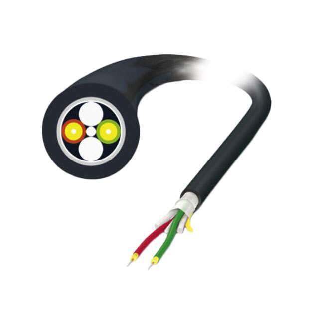
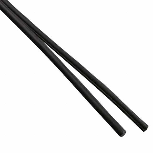
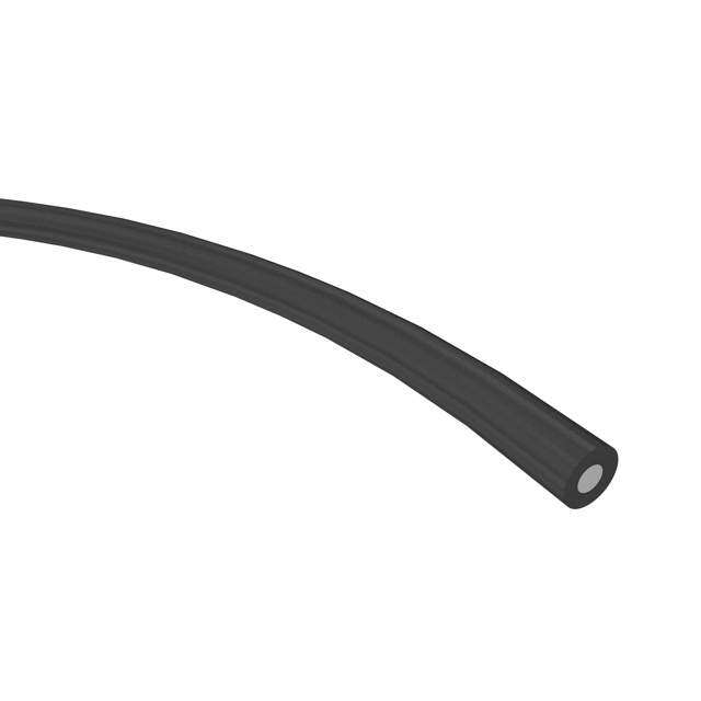
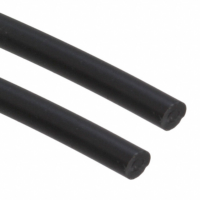
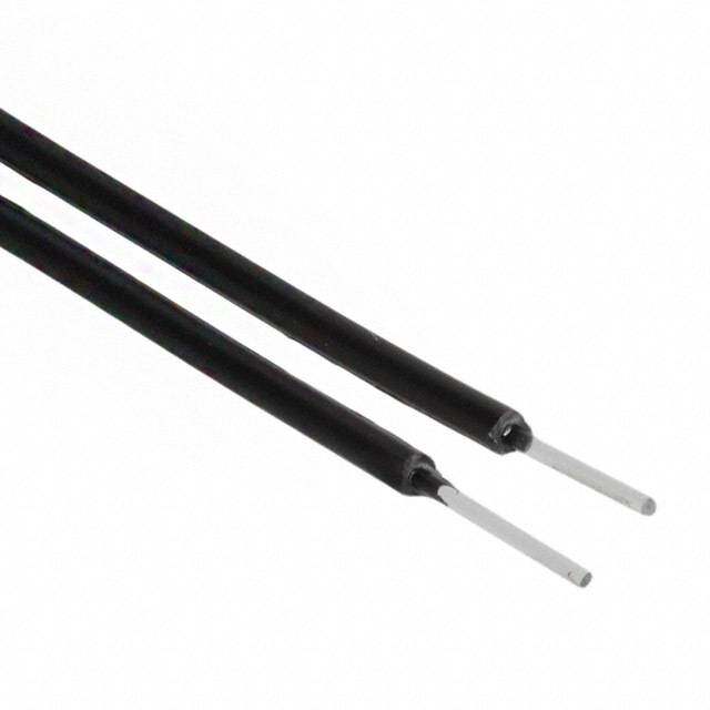
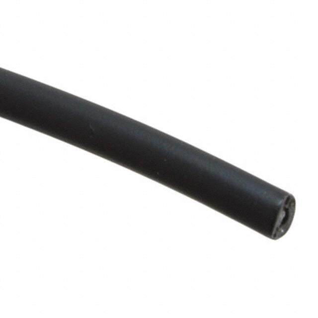
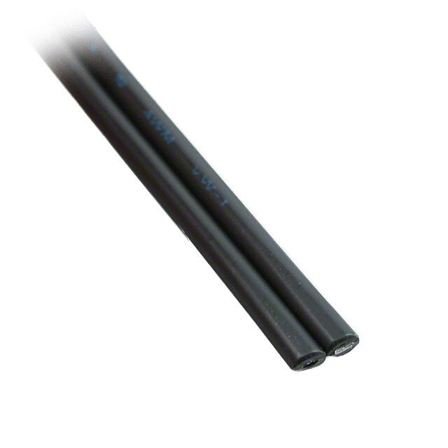
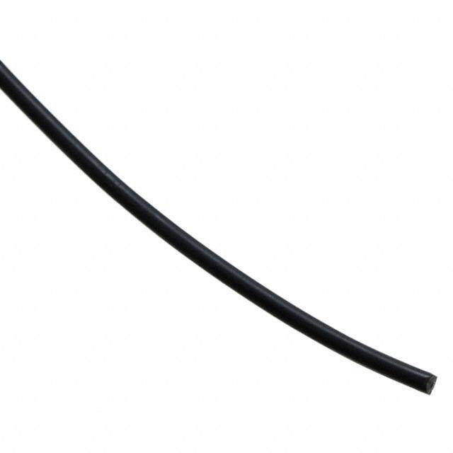
HFBR-RXXYYY Series (POF) HFBR-EXXYYY Series (POF) Plastic Optical Fiber Cable and Accessories for Versatile Link Data Sheet Cable Description Features The HFBR-R/EXXYYY series of plastic fiber optic cables • Compatible with Avago Versatile Link Family of con- are constructed of a single step-index fiber sheathed nectors and fiber optic components in a black polyethylene jacket. The duplex fiber consists • 1 mm diameter Plastic Optical Fiber (POF) in two of two simplex fibers joined with a zipcord web. grades: low cost standard POF with 0.22 dB/m typical attenuation, or high performance extra low loss POF Standard attenuation and extra low loss POF cables are with 0.19 dB/m typical attenuation identical except for attenuation specifications. Polyethylene jackets on all plastic fiber cables com- Applications ply with UL VW-1 flame retardant specification (UL file # E89328). • Industrial data links for factory automation and plant control Cables are available in unconnectored or connectored • Intra-system links; board-to-board, rack-to-rack options. Refer to the Ordering Guide for part number • Telecommunications switching systems information. • Computer-to-peripheral data links, PC bus extension • Proprietary LANs 500 • Digitized video • Medical instruments m • Reduction of lightning and voltage transient suscep- k 400 B/ d tibility – N O • High voltage isolation ATI 300 U N E T T A – R200 α 100 620 640 660 680 700 λ – WAVELENGTH – nm Figure 1. Typical POF attenuation vs. wavelength. HFBR-RXXYYY fig p2
Plastic Optical Fiber Specifications: HFBR-R/EXXYYY Absolute Maximum Ratings Parameter Symbol Min. Max. Unit Note Storage and Operating Temperature T -55 +85 °C S,O Recommended Operating Temperature T -40 +85 °C O Installation Temperature T -20 +70 °C 1 I Short Term Tensile Single Channel F 50 N 2 T Force Dual Channel F 100 N T Short Term Bend Radius r 25 mm 3, 4 Long Term Bend Radius r 35 mm Long Term Tensile Load F 1 N T Flexing 1000 Cycles 4 Mechanical/Optical Characteristics, T = -40 to +85°C unless otherwise specified. A Parameter Symbol Min. Typ.[5] Max. Unit Condition Cable Standard Cable, α 0.15 0.22 0.27 dB/m Source is HFBR-15XX O Attenuation Type "R" (660 mm LED, 0.5 NA) Extra Low Loss, 0.15 0.19 0.23 = 50 meters Type "E" Reference Standard Cable, α 0.12 0.19 0.24 dB/m Source is 650 nm, R Attenuation Type "R" 0.5 NA monochrometer, Extra Low Loss, 0.12 0.16 0.19 = 50 meters Type "E" Note 7, Figure 1 Numerical Aperture NA 0.46 0.47 0.50 >2 meters Diameter, Core and Cladding D 0.94 1.00 1.06 mm C Diameter, Jacket D 2.13 2.20 2.27 mm Simplex Cable J Propagation Delay Constant l/v 5.0 ns/m Note 6 Mass per Unit Length/Channel 5.3 g/m Without Connectors Cable Leakage Current I 12 nA 50 kV, = 0.3 meters L Refractive Index Core n 1.492 Cladding 1.417 Notes: 1. Installation temperature is the range over which the cable can be bent and pulled without damage. Below -20°C the cable becomes brittle and should not be subjected to mechanical stress. 2. Short Term Tensile Force is for less than 30 minutes. 3. Short Term Bend Radius is for less than 1 hour nonoperating. 4. 90° bend on 25 mm radius mandrel. Bend radius is the radius of the mandrel around which the cable is bent. 5. Typical data are at 25°C. 6. Propagation delay constant is the reciprocal of the group velocity for propagation delay of optical power. Group velocity is v=c/n where c is the velocity of light in free space (3xl08 m/s) and n is the effective core index of refraction. 7. Note that α rises at the rate of about 0.0067 dB/°C, where the thermal rise refers to the LED temperature changes above 25°C. Please refer to R Figure 1 which shows the typical plastic optical fiber attenuation versus wavelength at 25°C. 2
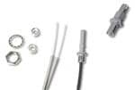
Plastic Fiber Connector Styles DUPLEX CONNECTOR STYLES Connector Description HFBR-4506 – Duplex Four connector styles are available for termination of plastic optical fiber: simplex, simplex latching, duplex and duplex HFBR-4526 latching. All connectors provide a snap-in action when mated to Versatile Link components. Simplex connectors are color coded to facilitate identification of transmitter and receiver connections. Duplex connectors are keyed so that proper orientation is ensured during insertion. If Duplex connectors provide convenient duplex cable the POF cable/connector will be used at extreme operat- termination and are keyed to prevent incorrect insertion ing temperatures or experience frequent and wide tem- into duplex configured modules. The duplex connector is perature cycling effects, the cable/connector attachment compatible with dual combinations of horizontal or vertical can be strengthened with an RTV adhesive (see Plastic Versatile Link components (e.g., two horizontal transmit- Connectoring Instructions for more detail). The connectors ters, two vertical receivers, a horizontal transmitter with a are made of a flame retardant VALOX UL94 V-0 material horizontal receiver, etc.). The duplex non-latching connec- (UL file # E121562). tor is available in parchment, off-white (HFBR-4506). SIMPLEX CONNECTOR STYLES HFBR-4516 – Duplex Latching HFBR-4501/4511 – Simplex , HFBR-4525 DUPLEX CRIMP RING HFBR-4526 The simplex connector provides a quick and stable connec- tion for applications that require a component-to-connec- tor retention force of 8 Newtons (1.8 lb.). These connectors are available in gray (HFBR-4501) or blue (HFBR-4511). The duplex latching connector is designed for rugged HFBR-4503/4513 – Simplex Latching applications requiring greater retention force than the nonlatching duplex connector. When inserting the duplex latching connector into a module, the connector latch HFBR-4525 mechanism should be aligned with the top surface of the dual combination of horizontal or vertical Versatile Link components. The duplex latching connector is available in gray (HFBR-4516). The simplex latching connector is designed for rugged applications requiring a greater retention force — 80 New- Feedthrough/Splice tons ( 18 lb.) — than provided by a simplex nonlatching HFBR-4505/4515 Bulkhead Adapter connector. When inserting the simplex latching connector into a module, the connector latch mechanism should be aligned with the top surface of the horizontal modules, or with the tall vertical side of the vertical modules. Mis- alignment of an inserted latching connector into either module will not result in a positive latch. The connector is The HFBR-4505/4515 adapter mates two simplex connec- released by depressing the rear section of the connector tors for panel/bulkhead feedthrough of HFBR-4501/4511 lever, and then pulling the connector assembly away from terminated plastic fiber cable. Maximum panel thickness the module housing. is 4.1 mm (0.16 inch). This adapter can serve as a cable in- line splice using two simplex connectors. The adapters are The simplex latching connector is available in gray (HFBR- available in gray (HFBR-4505) and blue (HFBR-4515). This 4503) or blue (HFBR-4513). adapter is not compatible with POF duplex, POF simplex latching, or HCS connectors. 3
Plastic Optical Fiber Connector Absolute Maximum Ratings Parameter Symbol Min. Max. Unit Note Storage and Operating Temperature T -40 85 °C 1 S,O Recommended Operating Temperature T -40 85 °C 1 O Installation Temperature T 0 70 °C 1 l Nut Torque T 0.7 N-m 2 N HFBR-4505/4515 Adapter 100 OzF-in. Notes: 1. Storage and Operating Temperatures refer to the ranges over which the connectors can be used when not subjected to mechanical stress. Installation Temperature refers to the ranges over which connectors may be installed onto the fiber and over which connectors can be con- nected and disconnected from transmitter and receiver modules. 2. Recommended nut torque is 0.57 N-m. Plastic Optical Fiber Connector Mechanical/Optical Characteristics T = -40 to +85°C, Unless Otherwise Specified. A Parameter Part Number Symbol Min. Typ.[1] Max. Units Temp. °C Note Retention Force, Simplex, F 7 8 N +25 2 R-C Connector to HFBR-4501/4511 3 -40 to +85 V ersatile Link Transmit- Simplex Latching, 47 80 +25 t ers and Receivers HFBR-4503/4513 11 -40 to +85 Duplex, 7 12 +25 HFBR-4506 4 -40 to +85 Duplex Latching, 50 80 +25 HFBR-4516 15 -40 to +85 Tensile Force, Simplex, F 8.5 22 N 3 T Connector to Cable HFBR-4501/4511 Simplex Latching, 8.5 22 HFBR-4503/4513 Duplex, HFBR-4506 14 35 Duplex Latching, 14 35 HFBR-4516 Adapter Connector HFBR-4505/4515 with α 0.7 1.5 2.8 dB 25 4, 5 CC to Connector Loss HFBR-4501/4511 Retention Force HFBR-4505/4515 with F 7 8 N R-B Connector to Adapter HFBR-4501/4511 Insertion Force, Simplex, F 8 30 N 6 I C onnector to Versatile HFBR-4501/4511 Link Transmitters and Simplex Latching, 16 35 Receivers HFBR-4503/4513 Duplex, HFBR-4506 13 46 Duplex Latching 22 51 HFBR-4516 Notes: 1. Typical data are at +25°C. 2. No perceivable reduction in retention force was observed after 2000 insertions. Retention force of non-latching connectors is lower at elevated temperatures. Latching connectors are recommended for applications where a high retention force at high temperatures is desired. 3. For applications where frequent temperature cycling over temperature extremes is expected, please contact Avago Technologies for alternate connectoring techniques. 4. Minimum and maximum limit for α for 0°C to +70°C temperature range. Typical value of α is at +25°C. CC CC 5. Factory polish or field polish per recommended procedure. 6. Destructive insertion force was typically at 178 N (40 lb.). 4
Step-by-Step Plastic Cable Connectoring Instructions The following step-by-step guide describes how to termi- When using the duplex connector and duplex cable, the nate plastic fiber optic cable. It is ideal for both field and separated duplex cable must be stripped to equal lengths factory installation. Connectors can be easily installed on each cable. This allows easy and proper seating of the on cable ends with wire strippers, cutters and a crimping cable into the duplex connector. tool. Finishing the cable is accomplished with the Avago HFBR-4593 Polishing Kit, consisting of a Polishing Fixture, 600 grit abrasive paper and 3 µm pink lapping film (3M Company, OC3-14). The connector can be used immedi- ately after polishing. Materials needed for plastic fiber termination are: 1. Avago Plastic Optical Fiber Cable (Example: HFBR- Step 2 RUS500, HFBR-RUD500, HFBR-EUS500, or HFBR- Place the crimp ring and connector over the end of the EUD500) cable; the fiber should protrude about 3 mm (0.12 in.) 2. Industrial Razor Blade or Wire Cutters through the end of the connector. Carefully position the ring so that it is entirely on the connector with the rim of 3. 16 Gauge Latching Wire Strippers (Example: Ideal StripmasterTM type 45-092). the crimp ring flush with the connector, leaving a small space between the crimp ring and the flange. Then crimp 4. HFBR-4597 Crimping Tool the ring in place with the crimping tool. One crimp tool is used for all POF connector crimping requirements. 5. HFBR-4593 Polishing Kit For applications with extreme temperature operation 6. One of the following connectors: or frequent temperature cycling, improved connector a) HFBR-4501/4503 Gray Simplex/Simplex Latching to cable attachment can be achieved with the use of an Connector and HFBR-4525 Simplex Crimp Ring RTV (GE Company, RTV-128 or Dow Corning 3145-RTV) adhesive. The RTV is placed into the connector prior to b) HFBR-4511/4513 Blue Simplex/Simplex Latching insertion of the fiber and the fiber is crimped normally. Connector and HFBR-4525 Simplex Crimp Ring The connector can be polished after the RTV has cured c) HFBR-4506 Parchment (off-white) Duplex Connector and is then ready for use. and HFBR-4526 Duplex Crimp Ring Note: By convention, place the gray connector on the trans d) HFBR-4516 Gray Latching Duplex Connector and mitter cable end and the blue connector on the receiver cable HFBR-4526 Duplex Crimp Ring end to maintain color coding (different color connectors are mechanically identical). Step 1 Simplex connector crimp rings cannot be used with duplex The zip cord structure of the duplex cable permits easy connectors and duplex connector crimp rings cannot be separation of the channels. The channels should be sepa- used with simplex connectors because of size differences. rated a minimum of 100 mm (4 in) to a maximum of 150 The simplex crimp has a dull luster appearance; the duplex mm (6 in) back from the ends to permit connectoring ring is glossy and has a thinner wall. and polishing. After cutting the cable to the desired length, strip off approximately 7 mm (0.3 in.) of the outer jacket with the 16 gauge wire strippers. Excess webbing on the duplex cable may have to be trimmed to allow the simplex or simplex latching connector to slide over the cable. 5
Step 4 Place the flush connector and polishing fixture on the dull side of the 3 µm pink lapping film and continue to polish the fiber and connector for approximately 25 strokes. The fiber end should be flat, smooth and clean. Step 3 This cable is now ready for use. Any excess fiber protruding from the connector end may Note: Use of the pink lapping film fine polishing step results in be cut off; however, the trimmed fiber should extend at approximately 2 dB improvement in coupling performance least 1.5 mm (0.06 in) from the connector end. of either a transmitterreceiver link or a bulkhead/splice over Insert the connector fully into the polishing fixture with a 600 grit polish alone. This fine polish is comparable to the the trimmed fiber protruding from the bottom of the Avago factory polish. The fine polishing step may be omitted fixture. This plastic polishing fixture can be used to polish where an extra 2 dB of optical power is not essential, as with two simplex connectors or simplex latching connectors short link lengths. Proper polishing of the tip of the fiber/con simultaneously, or one duplex connector. nector face results in a tip diameter between 2.5 mm (0.098 in.) minimum and 3.2 mm (0.126 in.) maximum.. Note: The four dots on the bottom of the polishing fixture are wear indicators. Replace the polishing fixture when any dot is no longer visible. Typically, the polishing fixture can HFBR-4593 Polishing Kit be used 10 times; 10 duplex connectors or 20 simplex con nectors, two at a time. Place the 600 grit abrasive paper on a flat smooth surface, pressing down on the connector, polish the fiber and the connector using a figure eight pattern of strokes until the connector is flush with the bottom of the polishing fixture. Wipe the connector and fixture with a clean cloth or tissue. 6
Ordering Guide for POF Connectors and Accessories Plastic Optical Fiber Connectors HFBR-4501 Gray Simplex Connector/Crimp Ring HFBR-4511 Blue Simplex Connector/Crimp Ring HFBR-4503 Gray Simplex Latching Connector with Crimp Ring HFBR-4513 Blue Simplex Latching Connector with Crimp Ring HFBR-4506 Parchment Duplex Connector with Crimp Ring HFBR-4516 Gray Duplex Latching Connector with Crimp Ring HFBR-4505 Gray Adapter (Bulkhead/Feedthrough) HFBR-4515 Blue Adapter (Bulkhead/Feedthrough) Plastic Optical Fiber Accessories HFBR-4522 500 HFBR-0500 Products Port Plugs HFBR-4525 1000 Simplex Crimp Rings HFBR-4526 500 Duplex Crimp Rings HFBR-4593 Polishing Kit (one polishing tool, two pieces 600 grit abrasive paper, and two pieces 3 µm pink lapping film) HFBR-4597 Plastic Fiber Crimping Tool Ordering Guide for POF Cable Cable Length Tolerances: For Example: The plastic cable length tolerances are: +10%/-0%. HFBR-RUD500 is a Standard Attenuation, Unconnectored, NOTE: By convention, pre-connectored simplex POF ca- Duplex, 500 meter cable. bles have gray and blue colored connectors on the op- posite ends of the same fiber; although oppositely col- HFBR-RLS001 is a Standard Attenuation, Latching Simplex ored, the connectors are mechanically identical. Duplex Connectored, Simplex, 1 meter cable. POF cables with duplex connectors use color- coded HFBR-RMD010 is a Standard Attenuation, Standard Duplex markings on the duplex fiber cable to differentiate be- Connectored, Duplex, 10 meter cable. tween the channel. HFBR-RMD100 is a Standard Attenuation, Standard Duplex Connectored, Duplex, 100 meter cable. HFBR- Cable Code Length Code R = Standard Attenuation POF (measured from tip of connector to tip of E = Extra Low Loss POF connector) 1-500 meters in 1 meter increments e.g. 015 = 15 meters Connector Code 1-10 meters in 1 decimeter increments U = Unconnectored e.g. 15D = 1.5 meters N = Standard Simplex Connectors L = Latching Simplex Connectors Channel Code M = Standard Duplex Connectors S = Simplex Cable T = Latching Duplex Connectors D = Duplex Zipcord Cable Note: Not all possible combinations reflect available part numbers. Please contact your local Avago representative for a list of current available cable part numbers. 7
Connector Applications Attachment to Avago Versatile Link Fiber Optic Components Bulkhead Feedthrough or Panel Mounting for HFBR-4501/4511 Simplex Connectors 8
Versatile Link Mechanical Dimensions Fiber Optic Cable Dimensions Panel Mounting – Bulkhead Feedthrough 1.0 POF (0.039) 0.230 HCS (0.009) HFBR-4505 (Gray)/4515 (Blue) Adapters Bulkhead Feedthrough with Two HFBR-4501/4511 Connectors All dimensions in mm (inches). All dimensions ±0.25 mm unless otherwise specified. 9
Versatile Link Mechanical Dimensions, continued HFBR-4516 (Parchment) Duplex Latching Connector HFBR-4506 (Parchment) Duplex Connector HFBR-4503 (Gray)/4513 (Blue) Simplex Latching Connector HFBR-4501 (Gray)/4511 (Blue) Simplex Connector All dimensions in mm (inches). All dimensions ±0.25 mm unless otherwise specified. For product information and a complete list of distributors, please go to our website: www.avagotech.com Avago, Avago Technologies, and the A logo are trademarks of Avago Technologies in the United States and other countries. Data subject to change. Copyright © 2005-2009 Avago Technologies. All rights reserved. Obsoletes 5988-3625EN AV02-1848EN - March 31, 2009
Mouser Electronics Authorized Distributor Click to View Pricing, Inventory, Delivery & Lifecycle Information: B roadcom Limited: HFBR-4593 HFBR-4503 HFBR-4513 HFBR-4513Z HFBR-4531 HFBR-4532 HFBR-4533 HFBR-4535 HFBR- END035 HFBR-END035Z HFBR-EUD500 HFBR-EUD500Z HFBR-EUS100 HFBR-EUS100Z HFBR-EUS500 HFBR-EUS500Z HFBR-RLS001 HFBR-RLS001Z HFBR-RLS010 HFBR-RLS010Z HFBR-RMD001 HFBR-RMD001Z HFBR-RMD002 HFBR-RMD002Z HFBR-RMD003 HFBR-RMD003Z HFBR-RMD005 HFBR-RMD005Z HFBR- RMD010 HFBR-RMD010Z HFBR-RNS001 HFBR-RNS001Z HFBR-RNS002 HFBR-RNS002Z HFBR-RNS005 HFBR-RNS005Z HFBR-RNS010 HFBR-RNS010Z HFBR-RTD001 HFBR-RTD001Z HFBR-RTD010 HFBR- RTD010Z HFBR-RTD45D HFBR-RTD45DZ HFBR-RUD100 HFBR-RUD100Z HFBR-RUD500 HFBR-RUD500Z HFBR-RUS100 HFBR-RUS100Z HFBR-RUS500 HFBR-RUS500Z HFBR-RWS002 HFBR-RWS002Z HFBR- RSD005Z