ICGOO在线商城 > FK18C0G2E391J
 Datasheet下载
- 型号: FK18C0G2E391J
- 制造商: TDK
- 库位|库存: xxxx|xxxx
- 要求:
| 数量阶梯 | 香港交货 | 国内含税 |
| +xxxx | $xxxx | ¥xxxx |
查看当月历史价格
查看今年历史价格
FK18C0G2E391J产品简介:
ICGOO电子元器件商城为您提供FK18C0G2E391J由TDK设计生产,在icgoo商城现货销售,并且可以通过原厂、代理商等渠道进行代购。 提供FK18C0G2E391J价格参考以及TDKFK18C0G2E391J封装/规格参数等产品信息。 你可以下载FK18C0G2E391J参考资料、Datasheet数据手册功能说明书, 资料中有FK18C0G2E391J详细功能的应用电路图电压和使用方法及教程。
| 参数 | 数值 |
| 产品目录 | |
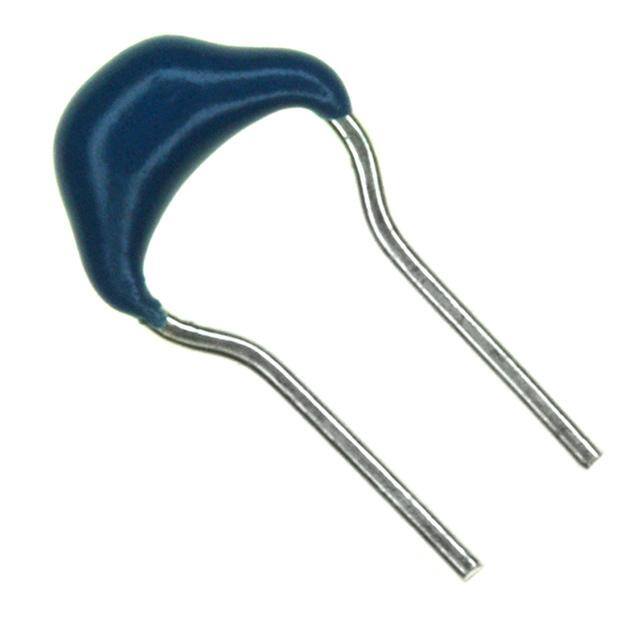
| 描述 | CAP CER 390PF 250V 5% RADIAL多层陶瓷电容器MLCC - 含引线 390pF 250volts C0G 5% |
| 产品分类 | |
| 品牌 | TDK |
| 产品手册 | |
| 产品图片 |
|
| rohs | 符合RoHS无铅 / 符合限制有害物质指令(RoHS)规范要求 |
| 产品系列 | MLCC,多层陶瓷电容器MLCC - 含引线,TDK FK18C0G2E391JFK |
| 数据手册 | |
| 产品型号 | FK18C0G2E391J |
| 产品 | General Type MLCCs |
| 产品目录绘图 |
|
| 产品目录页面 | |
| 产品种类 | 多层陶瓷电容器MLCC - 含引线 |
| 其它名称 | 445-4400 |
| 包装 | 散装 |
| 厚度(最大值) | - |
| 商标 | TDK |
| 外壳宽度 | 5.5 mm |
| 外壳长度 | 4 mm |
| 外壳高度 | 2.5 mm |
| 大小/尺寸 | 0.157" 长 x 0.098" 宽(4.00mm x 2.50mm) |
| 安装类型 | 通孔 |
| 容差 | 5 % |
| 封装 | Bulk |
| 封装/外壳 | 径向 |
| 封装类型 | Dipped |
| 工作温度 | -55°C ~ 125°C |
| 工作温度范围 | - 55 C to + 125 C |
| 工厂包装数量 | 500 |
| 应用 | 通用 |
| 引线形式 | 成型引线 - 扭结 |
| 引线间距 | 0.098"(2.50mm) |
| 引线间隔 | 2.5 mm |
| 最大工作温度 | + 125 C |
| 最小工作温度 | - 55 C |
| 标准包装 | 500 |
| 温度系数 | C0G,NP0 |
| 温度系数/代码 | C0G (NP0) |
| 特性 | - |
| 电压-额定 | 250V |
| 电压额定值 | 250 V |
| 电压额定值DC | 250 V |
| 电容 | 390 pF |
| 端接类型 | Radial |
| 等级 | - |
| 高度-安装(最大值) | 0.217"(5.50mm) |


- 商务部:美国ITC正式对集成电路等产品启动337调查
- 曝三星4nm工艺存在良率问题 高通将骁龙8 Gen1或转产台积电
- 太阳诱电将投资9.5亿元在常州建新厂生产MLCC 预计2023年完工
- 英特尔发布欧洲新工厂建设计划 深化IDM 2.0 战略
- 台积电先进制程称霸业界 有大客户加持明年业绩稳了
- 达到5530亿美元!SIA预计今年全球半导体销售额将创下新高
- 英特尔拟将自动驾驶子公司Mobileye上市 估值或超500亿美元
- 三星加码芯片和SET,合并消费电子和移动部门,撤换高东真等 CEO
- 三星电子宣布重大人事变动 还合并消费电子和移动部门
- 海关总署:前11个月进口集成电路产品价值2.52万亿元 增长14.8%


PDF Datasheet 数据手册内容提取
Multilayer Ceramic Capacitors Dipped radial lead type Mid voltage(Edc: 100 to 630V) FK series Type: FK28, FK18 FK24, FK14 FK26, FK16 FK20, FK11 FK22 Issue date: May 2011 • All specifications are subject to change without notice. (cid:127) Conformity to RoHS Directive: This means that, in conformity with EU Directive 2002/95/EC, lead, cadmium, mercury, hexavalent chromium, and specific bromine-based flame retardants, PBB and PBDE, have not been used, except for exempted applications.
(1/10) Dipped Radial Ceramic Capacitors Conformity to RoHS Directive Mid Voltage FK Series FEATURES (cid:127) Due to the technological progress in creating thinner layers of ceramic dielectric and achieving multilayer lamination, this product provides large electrostatic capacity. (cid:127) It maintains a high level of reliability under specified environ- mental conditions. (cid:127) Its residual inductance is small and it provides good frequency characteristics. (cid:127) The leads are formed with a "kink" to achieve consistent insertion heights and facilitate the release of gases during soldering for dramatically improved solderability. (cid:127) Also available are products that meet taping specifications for automatic insertions, which contribute to reducing on-board costs. PRODUCT IDENTIFICATION FK 28 C0G 1H 101 J (1) (2) (3) (4) (5) (6) (7) (1) Series name (4) Rated voltage Edc 2A 100V (2) Dimensions and shapes of lead wire 2E 250V 2J 630V L L T (5) Nominal capacitance W W The capacitance is expressed in three digit codes and in units of pico farads (pF). The first and second digits identify the first and second significant figures of the capacitance. ød ød The third digit identifies the multiplier. F F 102 1,000pF Fig.1 Fig.2 333 33,000pF 474 470,000pF Dimensions in mm Type L max. W max. T max. F ød Fig 28 4.0 5.5 2.5 5.0±1.0 7±2 0.5+0.1,–0.03 1 (6) Capacitance tolerance 24 4.5 5.5 2.5 5.0±1.0 7±2 0.5+0.1,–0.03 1 Symbol Tolerance 26 5.5 6.0 3.5 5.0±1.0 7±2 0.5+0.1,–0.03 1 J ±5% 20 5.5 7.0 4.0 5.0±1.0 7±2 0.5+0.1,–0.03 1 K ±10% 22 7.5 8.0 4.0 5.0±1.0 7±2 0.5+0.1,–0.03 1 18 4.0 5.5 2.5 2.5±0.8 5+3,–1 0.5+0.1,–0.03 2 (7) TDK internal code 14 4.5 5.5 2.5 2.5±0.8 5+3,–1 0.5+0.1,–0.03 2 16 5.5 6.0 3.5 2.5±0.8 5+3, –1 0.5+0.1, –0.03 2 11 5.5 7.0 4.0 2.5±0.8 5+3, –1 0.5+0.1, –0.03 2 (3) Capacitance temperature characteristics Class 1 (Temperature compensation) Temperature Capacitance change Temperature range characteristics C0G 0±30ppm/°C –55 to +125°C Class 2 (Temperature stable and general purpose) Temperature Capacitance change Temperature range characteristics X7R ±15% –55 to +125°C X7S ±22% –55 to +125°C (cid:127) Conformity to RoHS Directive: This means that, in conformity with EU Directive 2002/95/EC, lead, cadmium, mercury, hexavalent chromium, and specific bromine-based flame retardants, PBB and PBDE, have not been used, except for exempted applications. (cid:127) All specifications are subject to change without notice. 002-03 / 20110518 / e4942_fk.fm
(2/10) CAPACITANCE RANGES: CLASS 1 (TEMPERATURE COMPENSATION) FK28 AND FK18 TYPES SHAPES AND DIMENSIONS FK28 FK18 4.0max. 22..55mmaaxx.. 4.0max. 22..55mmaaxx.. x. x. a a m m 5 5 5. 5. ±2 +35–1 7 ø0.5+–00..013 ø0.5+–00..013 2.5±0.8 5.0±1.0 Dimensions in mm RATED VOLTAGE Edc: 100 to 250V Temperature Rated voltage Part No. Capacitance Tolerance characteristics Edc(V) FK28 type FK18 type C0G 100pF ±5% 100 FK28C0G2A101J FK18C0G2A101J C0G 120pF ±5% 100 FK28C0G2A121J FK18C0G2A121J C0G 150pF ±5% 100 FK28C0G2A151J FK18C0G2A151J C0G 180pF ±5% 100 FK28C0G2A181J FK18C0G2A181J C0G 220pF ±5% 100 FK28C0G2A221J FK18C0G2A221J C0G 270pF ±5% 100 FK28C0G2A271J FK18C0G2A271J C0G 330pF ±5% 100 FK28C0G2A331J FK18C0G2A331J C0G 390pF ±5% 100 FK28C0G2A391J FK18C0G2A391J C0G 470pF ±5% 100 FK28C0G2A471J FK18C0G2A471J C0G 560pF ±5% 100 FK28C0G2A561J FK18C0G2A561J C0G 680pF ±5% 100 FK28C0G2A681J FK18C0G2A681J C0G 820pF ±5% 100 FK28C0G2A821J FK18C0G2A821J C0G 1000pF ±5% 100 FK28C0G2A102J FK18C0G2A102J C0G 1200pF ±5% 100 FK28C0G2A122J FK18C0G2A122J C0G 100pF ±5% 250 FK28C0G2E101J FK18C0G2E101J C0G 120pF ±5% 250 FK28C0G2E121J FK18C0G2E121J C0G 150pF ±5% 250 FK28C0G2E151J FK18C0G2E151J C0G 180pF ±5% 250 FK28C0G2E181J FK18C0G2E181J C0G 220pF ±5% 250 FK28C0G2E221J FK18C0G2E221J C0G 270pF ±5% 250 FK28C0G2E271J FK18C0G2E271J C0G 330pF ±5% 250 FK28C0G2E331J FK18C0G2E331J C0G 390pF ±5% 250 FK28C0G2E391J FK18C0G2E391J C0G 470pF ±5% 250 FK28C0G2E471J FK18C0G2E471J C0G 560pF ±5% 250 FK28C0G2E561J FK18C0G2E561J C0G 680pF ±5% 250 FK28C0G2E681J FK18C0G2E681J (cid:127) All specifications are subject to change without notice. 002-03 / 20110518 / e4942_fk.fm
(3/10) FK24 AND FK14 TYPES SHAPES AND DIMENSIONS FK24 FK14 4.5max. 2.5max. 4.5max. 2.5max. x. x. a a m m 5 5 5. 5. ±2 +35–1 7 ø0.5+–00..013 ø0.5+–00..013 2.5±0.8 5.0±1.0 Dimensions in mm RATED VOLTAGE Edc: 100 to 250V Temperature Rated voltage Part No. Capacitance Tolerance characteristics Edc(V) FK24 type FK14 type C0G 1000pF ±5% 100 FK24C0G2A102J FK14C0G2A102J C0G 1200pF ±5% 100 FK24C0G2A122J FK14C0G2A122J C0G 1500pF ±5% 100 FK24C0G2A152J FK14C0G2A152J C0G 1800pF ±5% 100 FK24C0G2A182J FK14C0G2A182J C0G 2200pF ±5% 100 FK24C0G2A222J FK14C0G2A222J C0G 2700pF ±5% 100 FK24C0G2A272J FK14C0G2A272J C0G 3300pF ±5% 100 FK24C0G2A332J FK14C0G2A332J C0G 3900pF ±5% 100 FK24C0G2A392J FK14C0G2A392J C0G 4700pF ±5% 100 FK24C0G2A472J FK14C0G2A472J C0G 820pF ±5% 250 FK24C0G2E821J FK14C0G2E821J C0G 1000pF ±5% 250 FK24C0G2E102J FK14C0G2E102J C0G 1200pF ±5% 250 FK24C0G2E122J FK14C0G2E122J C0G 1500pF ±5% 250 FK24C0G2E152J FK14C0G2E152J C0G 1800pF ±5% 250 FK24C0G2E182J FK14C0G2E182J C0G 2200pF ±5% 250 FK24C0G2E222J FK14C0G2E222J C0G 2700pF ±5% 250 FK24C0G2E272J FK14C0G2E272J (cid:127) All specifications are subject to change without notice. 002-03 / 20110518 / e4942_fk.fm
(4/10) FK26 AND FK16 TYPES SHAPES AND DIMENSIONS FK26 FK16 5.5max. 3.5max. 5.5max. 3.5max. x. x. a a m m 0 0 6. 6. ±2 +35–1 7 ø0.5+–00..013 ø0.5+–00..013 2.5±0.8 5.0±1.0 Dimensions in mm RATED VOLTAGE Edc: 100 to 630V Temperature Rated voltage Part No. Capacitance Tolerance characteristics Edc(V) FK26 type FK16 type C0G 3900pF ±5% 100 FK26C0G2A392J FK16C0G2A392J C0G 4700pF ±5% 100 FK26C0G2A472J FK16C0G2A472J C0G 5600pF ±5% 100 FK26C0G2A562J FK16C0G2A562J C0G 6800pF ±5% 100 FK26C0G2A682J FK16C0G2A682J C0G 8200pF ±5% 100 FK26C0G2A822J FK16C0G2A822J C0G 10000pF ±5% 100 FK26C0G2A103J FK16C0G2A103J C0G 3300pF ±5% 250 FK26C0G2E332J C0G 3900pF ±5% 250 FK26C0G2E392J C0G 4700pF ±5% 250 FK26C0G2E472J C0G 5600pF ±5% 250 FK26C0G2E562J C0G 6800pF ±5% 250 FK26C0G2E682J C0G 8200pF ±5% 250 FK26C0G2E822J C0G 100pF ±5% 630 FK26C0G2J101J C0G 120pF ±5% 630 FK26C0G2J121J C0G 150pF ±5% 630 FK26C0G2J151J C0G 180pF ±5% 630 FK26C0G2J181J C0G 220pF ±5% 630 FK26C0G2J221J C0G 270pF ±5% 630 FK26C0G2J271J C0G 330pF ±5% 630 FK26C0G2J331J C0G 390pF ±5% 630 FK26C0G2J391J C0G 470pF ±5% 630 FK26C0G2J471J C0G 560pF ±5% 630 FK26C0G2J561J C0G 680pF ±5% 630 FK26C0G2J681J C0G 820pF ±5% 630 FK26C0G2J821J C0G 1000pF ±5% 630 FK26C0G2J102J C0G 1200pF ±5% 630 FK26C0G2J122J C0G 1500pF ±5% 630 FK26C0G2J152J C0G 1800pF ±5% 630 FK26C0G2J182J C0G 2200pF ±5% 630 FK26C0G2J222J C0G 2700pF ±5% 630 FK26C0G2J272J C0G 3300pF ±5% 630 FK26C0G2J332J (cid:127) All specifications are subject to change without notice. 002-03 / 20110518 / e4942_fk.fm
(5/10) FK20 AND FK11 TYPES SHAPES AND DIMENSIONS FK20 FK11 5.5max. 4.0max. 5.5max. 4.0max. x. x. a a m m 0 0 7. 7. ±2 +35–1 7 ø0.5+–00..013 ø0.5+–00..013 2.5±0.8 5.0±1.0 Dimensions in mm RATED VOLTAGE Edc: 100 to 630V Temperature Rated voltage Part No. Capacitance Tolerance characteristics Edc(V) FK20 type FK11 type C0G 15000pF ±5% 100 FK20C0G2A153J FK11C0G2A153J C0G 22000pF ±5% 100 FK20C0G2A223J FK11C0G2A223J C0G 33000pF ±5% 100 FK20C0G2A333J FK11C0G2A333J C0G 47000pF ±5% 100 FK20C0G2A473J FK11C0G2A473J C0G 10000pF ±5% 250 FK20C0G2E103J C0G 15000pF ±5% 250 FK20C0G2E153J C0G 3900pF ±5% 630 FK20C0G2J392J C0G 4700pF ±5% 630 FK20C0G2J472J C0G 5600pF ±5% 630 FK20C0G2J562J C0G 6800pF ±5% 630 FK20C0G2J682J FK22 TYPE SHAPES AND DIMENSIONS 7.5max. 4.0max. x. a m 0 8. 2 ± 7 ø0.5+–00..013 5.0±1.0 Dimensions in mm RATED VOLTAGE Edc: 100 to 630V Temperature Rated voltage Part No. Capacitance Tolerance characteristics Edc(V) FK22 type C0G 68000pF ±5% 100 FK22C0G2A683J C0G 0.1µF ±5% 100 FK22C0G2A104J C0G 22000pF ±5% 250 FK22C0G2E223J C0G 33000pF ±5% 250 FK22C0G2E333J C0G 47000pF ±5% 250 FK22C0G2E473J C0G 8200pF ±5% 630 FK22C0G2J822J C0G 10000pF ±5% 630 FK22C0G2J103J C0G 15000pF ±5% 630 FK22C0G2J153J C0G 22000pF ±5% 630 FK22C0G2J223J (cid:127) All specifications are subject to change without notice. 002-03 / 20110518 / e4942_fk.fm
(6/10) CAPACITANCE RANGES: CLASS 2 FK28 AND FK18 TYPES SHAPES AND DIMENSIONS FK28 FK18 4.0max. 22..55mmaaxx.. 4.0max. 22..55mmaaxx.. x. x. a a m m 5 5 5. 5. ±2 +35–1 7 ø0.5+–00..013 ø0.5+–00..013 2.5±0.8 5.0±1.0 Dimensions in mm RATED VOLTAGE Edc: 100 to 250V Temperature Rated voltage Part No. Capacitance Tolerance characteristics Edc(V) FK28 type FK18 type X7R 1000pF ±10% 100 FK28X7R2A102K FK18X7R2A102K X7R 1500pF ±10% 100 FK28X7R2A152K FK18X7R2A152K X7R 2200pF ±10% 100 FK28X7R2A222K FK18X7R2A222K X7R 3300pF ±10% 100 FK28X7R2A332K FK18X7R2A332K X7R 4700pF ±10% 100 FK28X7R2A472K FK18X7R2A472K X7R 6800pF ±10% 100 FK28X7R2A682K FK18X7R2A682K X7R 10000pF ±10% 100 FK28X7R2A103K FK18X7R2A103K X7R 15000pF ±10% 100 FK28X7R2A153K FK18X7R2A153K X7R 22000pF ±10% 100 FK28X7R2A223K FK18X7R2A223K X7S 33000pF ±10% 100 FK28X7S2A333K FK18X7S2A333K X7S 47000pF ±10% 100 FK28X7S2A473K FK18X7S2A473K X7S 68000pF ±10% 100 FK28X7S2A683K FK18X7S2A683K X7S 0.1µF ±10% 100 FK28X7S2A104K FK18X7S2A104K (cid:127) All specifications are subject to change without notice. 002-03 / 20110518 / e4942_fk.fm
(7/10) FK24 AND FK14 TYPES SHAPES AND DIMENSIONS FK24 FK14 4.5max. 2.5max. 4.5max. 2.5max. x. x. a a m m 5 5 5. 5. ±2 +35–1 7 ø0.5+–00..013 ø0.5+–00..013 2.5±0.8 5.0±1.0 Dimensions in mm RATED VOLTAGE Edc: 100 to 250V Temperature Rated voltage Part No. Capacitance Tolerance characteristics Edc(V) FK24 type FK14 type X7R 1000pF ±10% 100 FK24X7R2A102K FK14X7R2A102K X7R 1500pF ±10% 100 FK24X7R2A152K FK14X7R2A152K X7R 2200pF ±10% 100 FK24X7R2A222K FK14X7R2A222K X7R 3300pF ±10% 100 FK24X7R2A332K FK14X7R2A332K X7R 4700pF ±10% 100 FK24X7R2A472K FK14X7R2A472K X7R 6800pF ±10% 100 FK24X7R2A682K FK14X7R2A682K X7R 10000pF ±10% 100 FK24X7R2A103K FK14X7R2A103K X7R 15000pF ±10% 100 FK24X7R2A153K FK14X7R2A153K X7R 22000pF ±10% 100 FK24X7R2A223K FK14X7R2A223K X7R 33000pF ±10% 100 FK24X7R2A333K FK14X7R2A333K X7R 47000pF ±10% 100 FK24X7R2A473K FK14X7R2A473K X7R 68000pF ±10% 100 FK24X7R2A683K FK14X7R2A683K X7R 0.1µF ±10% 100 FK24X7R2A104K FK14X7R2A104K X7S 0.15µF ±10% 100 FK24X7S2A154K FK14X7S2A154K X7S 0.22µF ±10% 100 FK24X7S2A224K FK14X7S2A224K X7S 0.33µF ±10% 100 FK24X7S2A334K FK14X7S2A334K X7S 0.47µF ±10% 100 FK24X7S2A474K FK14X7S2A474K X7S 0.68µF ±10% 100 FK24X7S2A684K FK14X7S2A684K X7S 1µF ±10% 100 FK24X7S2A105K FK14X7S2A105K X7R 1000pF ±10% 250 FK24X7R2E102K FK14X7R2E102K X7R 1500pF ±10% 250 FK24X7R2E152K FK14X7R2E152K X7R 2200pF ±10% 250 FK24X7R2E222K FK14X7R2E222K X7R 3300pF ±10% 250 FK24X7R2E332K FK14X7R2E332K X7R 4700pF ±10% 250 FK24X7R2E472K FK14X7R2E472K X7R 6800pF ±10% 250 FK24X7R2E682K FK14X7R2E682K X7R 10000pF ±10% 250 FK24X7R2E103K FK14X7R2E103K X7R 15000pF ±10% 250 FK24X7R2E153K FK14X7R2E153K X7R 22000pF ±10% 250 FK24X7R2E223K FK14X7R2E223K (cid:127) All specifications are subject to change without notice. 002-03 / 20110518 / e4942_fk.fm
(8/10) FK26 AND FK16 TYPES SHAPES AND DIMENSIONS FK26 FK16 5.5max. 3.5max. 5.5max. 3.5max. x. x. a a m m 0 0 6. 6. ±2 +35–1 7 ø0.5+–00..013 ø0.5+–00..013 2.5±0.8 5.0±1.0 Dimensions in mm RATED VOLTAGE Edc: 100 to 630V Temperature Rated voltage Part No. Capacitance Tolerance characteristics Edc(V) FK26 type FK16 type X7R 33000pF ±10% 100 FK26X7R2A333K FK16X7R2A333K X7R 47000pF ±10% 100 FK26X7R2A473K FK16X7R2A473K X7R 68000pF ±10% 100 FK26X7R2A683K FK16X7R2A683K X7R 0.1µF ±10% 100 FK26X7R2A104K FK16X7R2A104K X7R 0.15µF ±10% 100 FK26X7R2A154K FK16X7R2A154K X7R 0.22µF ±10% 100 FK26X7R2A224K FK16X7R2A224K X7R 0.33µF ±10% 100 FK26X7R2A334K FK16X7R2A334K X7R 0.47µF ±10% 100 FK26X7R2A474K FK16X7R2A474K X7R 0.68µF ±10% 100 FK26X7R2A684K FK16X7R2A684K X7R 1µF ±10% 100 FK26X7R2A105K FK16X7R2A105K X7S 1.5µF ±10% 100 FK26X7S2A155K FK16X7S2A155K X7S 2.2µF ±10% 100 FK26X7S2A225K FK16X7S2A225K X7R 15000pF ±10% 250 FK26X7R2E153K X7R 22000pF ±10% 250 FK26X7R2E223K X7R 33000pF ±10% 250 FK26X7R2E333K X7R 47000pF ±10% 250 FK26X7R2E473K X7R 68000pF ±10% 250 FK26X7R2E683K X7R 0.1µF ±10% 250 FK26X7R2E104K X7R 1000pF ±10% 630 FK26X7R2J102K X7R 1500pF ±10% 630 FK26X7R2J152K X7R 2200pF ±10% 630 FK26X7R2J222K X7R 3300pF ±10% 630 FK26X7R2J332K X7R 4700pF ±10% 630 FK26X7R2J472K X7R 6800pF ±10% 630 FK26X7R2J682K X7R 10000pF ±10% 630 FK26X7R2J103K X7R 15000pF ±10% 630 FK26X7R2J153K X7R 22000pF ±10% 630 FK26X7R2J223K X7R 33000pF ±10% 630 FK26X7R2J333K (cid:127) All specifications are subject to change without notice. 002-03 / 20110518 / e4942_fk.fm
(9/10) FK20 AND FK11 TYPES SHAPES AND DIMENSIONS FK20 FK11 5.5max. 4.0max. 5.5max. 4.0max. x. x. a a m m 0 0 7. 7. ±2 +35–1 7 ø0.5+–00..013 ø0.5+–00..013 2.5±0.8 5.0±1.0 Dimensions in mm RATED VOLTAGE Edc: 100 to 630V Temperature Rated voltage Part No. Capacitance Tolerance characteristics Edc(V) FK20 type FK11 type X7R 0.33µF ±10% 100 FK20X7R2A334K FK11X7R2A334K X7R 0.47µF ±10% 100 FK20X7R2A474K FK11X7R2A474K X7R 0.68µF ±10% 100 FK20X7R2A684K FK11X7R2A684K X7R 1µF ±10% 100 FK20X7R2A105K FK11X7R2A105K X7R 1.5µF ±10% 100 FK20X7R2A155K FK11X7R2A155K X7R 2.2µF ±10% 100 FK20X7R2A225K FK11X7R2A225K X7S 3.3µF ±10% 100 FK20X7S2A335K FK11X7S2A335K X7S 4.7µF ±10% 100 FK20X7S2A475K FK11X7S2A475K X7R 0.1µF ±10% 250 FK20X7R2E104K X7R 0.15µF ±10% 250 FK20X7R2E154K X7R 0.22µF ±10% 250 FK20X7R2E224K X7R 47000pF ±10% 630 FK20X7R2J473K X7R 68000pF ±10% 630 FK20X7R2J683K FK22 TYPE SHAPES AND DIMENSIONS 7.5max. 4.0max. x. a m 0 8. 2 ± 7 ø0.5+–00..013 5.0±1.0 Dimensions in mm RATED VOLTAGE Edc: 100 to 630V Temperature Rated voltage Part No. Capacitance Tolerance characteristics Edc(V) FK22 type X7R 0.68µF ±10% 100 FK22X7R2A684K X7R 1µF ±10% 100 FK22X7R2A105K X7R 1.5µF ±10% 100 FK22X7R2A155K X7R 2.2µF ±10% 100 FK22X7R2A225K X7R 0.15µF ±10% 250 FK22X7R2E154K X7R 0.22µF ±10% 250 FK22X7R2E224K X7R 0.33µF ±10% 250 FK22X7R2E334K X7R 0.47µF ±10% 250 FK22X7R2E474K X7R 0.1µF ±10% 630 FK22X7R2J104K (cid:127) For more information about products with other capacitance or other data, please contact us. (cid:127) All specifications are subject to change without notice. 002-03 / 20110518 / e4942_fk.fm
(10/10) PACKAGING STYLES TAPING DIMENSIONS FK1 Series (FK18/FK14/FK16/FK11 Types) Symbol Dimensions(mm) t P 12.7±1.0 P2 P P ∆h P0∗1 12.7±0.3 P1 5.1±0.7 P2 6.35±1.3 W0 12.0±1.0 W1 9.0±0.5 P1 W2∗2 3.0max. W3 18.0+1.0, –0.5 H0 H0 16.0±0.5 W2 1.0max. t 0.6±0.2 L0 W1 L0 11.0max. W0 W3 F 2.5+0.5, –0.2 ød ø0.5+0.1, –0.03 øD ø4.0±0.2 ∆h 0±2 F øD ∗1 Accumulated pitch tolerance shall be ±2mm for 20 pitches. ød ∗2 Adhesive tape shall not stick out from carrier tape. P0 FK2 Series (FK28/FK24/FK26/FK20/FK22 Types) Symbol Dimensions(mm) t P 12.7±1.0 P2 P P ∆h P0∗1 12.7±0.3 P1 3.85±0.7 P2 6.35±1.3 W0 12.0±1.0 W1 9.0±0.5 P1 W2∗2 3.0max. H0 W2 WH03 1168..00±+10..05, –0.5 1.0max. L0 W1 t 0.6±0.2 W0 W3 L0 11.0max. F 5.0+0.8, –0.2 ød ø0.5+0.1, –0.03 øD ø4.0±0.2 F øD ∆h 0±2 ød ∗1 Accumulated pitch tolerance shall be ±2mm for 20 pitches. P0 ∗2 Adhesive tape shall not stick out from carrier tape. PACKAGING QUANTITIES Type Quantity FK18, FK28 FK14, FK24 2000 pieces/1box FK16, FK26 FK11, FK20, K22 1500 pieces/1box (cid:127) All specifications are subject to change without notice. 002-03 / 20110518 / e4942_fk.fm