ICGOO在线商城 > FH34SJ-8S-0.5SH(50)
.jpg)
 Datasheet下载
- 型号: FH34SJ-8S-0.5SH(50)
- 制造商: Hirose Electric
- 库位|库存: xxxx|xxxx
- 要求:
| 数量阶梯 | 香港交货 | 国内含税 |
| +xxxx | $xxxx | ¥xxxx |
查看当月历史价格
查看今年历史价格
FH34SJ-8S-0.5SH(50)产品简介:
ICGOO电子元器件商城为您提供FH34SJ-8S-0.5SH(50)由Hirose Electric设计生产,在icgoo商城现货销售,并且可以通过原厂、代理商等渠道进行代购。 提供FH34SJ-8S-0.5SH(50)价格参考以及Hirose ElectricFH34SJ-8S-0.5SH(50)封装/规格参数等产品信息。 你可以下载FH34SJ-8S-0.5SH(50)参考资料、Datasheet数据手册功能说明书, 资料中有FH34SJ-8S-0.5SH(50)详细功能的应用电路图电压和使用方法及教程。
| 参数 | 数值 |
| 产品目录 | |
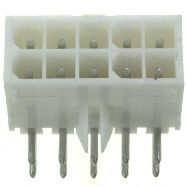
| 描述 | CONN FFC/FPC 8POS .5MM SMD GOLD |
| 产品分类 | |
| FFC,FCB厚度 | 0.30mm |
| 品牌 | Hirose Electric Co Ltd |
| 数据手册 | |
| 产品图片 |
|
| 产品型号 | FH34SJ-8S-0.5SH(50) |
| rohs | 无铅 / 符合限制有害物质指令(RoHS)规范要求 |
| 产品系列 | FH34SJ |
| 其它名称 | HFT208CT |
| 包装 | 剪切带 (CT) |
| 外壳材料 | 液晶聚合物(LCP), 不含卤素的 |
| 安装类型 | 表面贴装,直角 |
| 工作温度 | -55°C ~ 85°C |
| 扁平柔性类型 | FFC, FPC |
| 材料可燃性等级 | UL94 V-0 |
| 板上高度 | 0.039"(1.00mm) |
| 标准包装 | 1 |
| 特性 | 零插入力(ZIF) |
| 特色产品 | http://www.digikey.cn/product-highlights/zh/fh34s-series/51744 |
| 电缆端类型 | 锥形 |
| 端接 | |
| 致动器材料 | - |
| 触头材料 | 磷青铜 |
| 触头镀层 | 金 |
| 连接器/触头类型 | 触点, 顶部 |
| 针脚数 | 8 |
| 锁定功能 | 旋转锁,背锁 |
| 间距 | 0.020"(0.50mm) |
| 额定电压 | 50V |
| 额定电流 | 0.5A |
.JPG)


- 商务部:美国ITC正式对集成电路等产品启动337调查
- 曝三星4nm工艺存在良率问题 高通将骁龙8 Gen1或转产台积电
- 太阳诱电将投资9.5亿元在常州建新厂生产MLCC 预计2023年完工
- 英特尔发布欧洲新工厂建设计划 深化IDM 2.0 战略
- 台积电先进制程称霸业界 有大客户加持明年业绩稳了
- 达到5530亿美元!SIA预计今年全球半导体销售额将创下新高
- 英特尔拟将自动驾驶子公司Mobileye上市 估值或超500亿美元
- 三星加码芯片和SET,合并消费电子和移动部门,撤换高东真等 CEO
- 三星电子宣布重大人事变动 还合并消费电子和移动部门
- 海关总署:前11个月进口集成电路产品价值2.52万亿元 增长14.8%


PDF Datasheet 数据手册内容提取
0.5 mm Pitch, 1.0 mm above the board Top and Bottom Contact, Back-Flip actuator Flexible Printed Circuit & Flexible Flat Cable ZIF Connectors FH34(S)Series Increased FPC/FFC holding force Space saving (30 pos. shown) Actuator Metal fittings 1.0mm 17mm 3.2mm Easy FPC/FFC insertion Back opening rotating All four sides are 17 m m chamfered. Top contacts (cid:2) Features FPC / FFC 1. Low-profile With the 1.0 mm above the board and width of 3.8 mm the Ready to insert FPC/FFC connectors are used in space saving applications. 2. Increased FPC/FFC retention DDeelliivveerreedd wwiitthh As compared with existing similar construction connectors: tthhee aaccttuuaattoorr ooppeenn * In horizontal direction: Approximately 2.6 times * In vertical direction: Approximately 2 times 3. Unique Back-Flip rotating actuator The rotating actuator opens from the back of the connector, assuring reliable electrical and mechanical connection. 4. Easy FPC insertion and reliable electrical connection Proven Flip Lock actuator allows easy insertion of FPC and provides a tactile sensation when fully closed, confirming FFPPCC complete electrical and mechanical connection. 5. Delivered with the actuator open FPC/FFC inserted and retained. FPC/FPC can be immediately inserted without the need for the Completed electrical and mechanical connection. opening of the actuator. 6. Accepts standard FPC thickness 0.3mm thick standard Flexible Printed Circuit (FPC) can be used. This is the only ultra-low profile ZIF connector using standard FPC. 7. Compatible with existing connectors. FPC/FFC and PCB mounting patterns are the same as for the FH19SC Series (bottom contact), allowing the use of both connectors for interconnections between two boards or replacement of the connectors. 8. Conductive traces on the PCB can run under the connector No exposed contacts on the bottom of the connector. 9. Board placement with automatic equipment Flat upper surface and tape and reel packaging facilitate vacuum Compatible with existing connectors.(FH19SC SERIES) pick-up and placement. Standard reel packaging contains 5000 connectors. 10.Halogen-free* (FH34SJ,FH34SW,FH34SRJ) *As defined by IEC61249-2-21 Br-900ppm maximum, Cl-900ppm maximum, Cl + Br combined-1,500ppm maximum 2012.3 1
FH34(S)Series(cid:3) 0.5 mm Pitch, 1.0 mm above the board Top and Bottom Contact, Back-Flip actuator Flexible Printed Circuit & Flexible Flat Cable ZIF Connectors (cid:2) Specifications Operating temperature range: Storage temperature range: Current rating 0.5 A (Note 1) -55 to +85°C (Note 1) -10 to +50°C (Note 2) Ratings Operating humidity range: Storage humidity range: Voltage rating 50 Vrms AC Relative humidity 90% max. (No condensation) Relative humidity 90% max. (No condensation) Recommended FPC/FFC Thickness: 0.3 ± 0.03 mm, Gold plated contact pads Item Specification Conditions 1. Insulation resistance 500 Mø min. 100 V DC 2. Withstanding voltage No flashover or insulation breakdown 250 Vrms AC / one minute 100 mø max. 3. Contact resistance 1 mA, AC / DC 20mV max (AC: 1kHz) * Including FPC and FFC conductor resistance Contact resistance: 100 mø max. 4. Durability 20 cycles No damage, cracks, or parts dislocation No electrical discontinuity of 1µs or longer Frequency: 10 to 55 Hz, single amplitude of 0.75 5. Vibration Contact resistance: 100 mø max. mm, 10 cycles in each of the 3 axis No damage, cracks, or parts dislocation No electrical discontinuity of 1µs or longer Acceleration of 981m/s2, 6 ms duration, sine half- 6. Shock Contact resistance: 100 mø max. wave, 3 cycles in each of the 3 axis No damage, cracks, or parts dislocation Contact resistance: 100 mø max. 7. Humidity (Steady state) Insulation resistance: 50 Mø min. 96 hours at 40°C and humidity of 90 to 95% No damage, cracks, or parts dislocation Contact resistance: 100 mø max. Temperature :-55°C/+15°C to +35°C/+85°C/+15°C to +35°C 8. Temperature cycle Insulation resistance: 50 Mø min. Time: 30 / 2 to 3 / 30 / 2 to 3 minutes No damage, cracks, or parts dislocation 5 cycles Reflow: At the recommended temperature profile 9. Resistance to soldering heat No deformation of components affecting performance Manual soldering: 350°C ±5°C for 5 seconds (Note 3) Note1: When passing the current through all of the contacts, use 70% of the rated current. Note2: Includes temperature rise caused by current flow. Note3: The term "storage" refers to products stored for a long period prior to mounting and use. The operating temperature and humidity range covers the non-conducting condition of installed connectors in storage, shipment or during transportation after board mounting. Note4: Information contained in this catalog represents general requirements for this Series. Contact us for the drawings and specifications for a specific part number shown. (cid:2) Materials Part Material Finish Remarks FH34S series FH34SJ series Color:Beige LCP FH34SW series FH34SR series Color:Gray FH34SRJ series UL94V-0 FH34S series Insulator FH34SJ series Color:Black PA FH34SR series FH34SRJ series FH34SW series Color:Light brown UL94HB FH34SJ series LCP(8pos.) Color:Black UL94V-0 FH34SR series Contacts Phosphor bronze Gold plating with nickel barrier ------- Metalfittings Phosphor bronze Pure tin reflow plating ------- (cid:2) Ordering information FH 34S J - 30S - 0.5 SH (50) 1 2 3 4 5 6 7 1 Series name : FH 4 Number of positions : 4 to 34 2 Series No. : 34S 5 Contact pitch: 0.5mm 3 Blank : Standard 6 Termination type J : Top contact, Halogen-free SH : SMT horizontal mounting type (Flame retardance UL94V-0). 7 Plating specifications W : Top contact, Halogen-free (50)…Gold plating with nickel barrier (Flame retardance UL94HB). R : Bottom contact RJ : Bottom contact, halogen-free (Flame retardance UL94V-0). 2
FH34(S)Series(cid:3) 0.5 mm Pitch, 1.0 mm above the board Top and Bottom Contact, Back-Flip actuator Flexible Printed Circuit & Flexible Flat Cable ZIF Connectors (cid:2) Connector Dimensions A±0.15 B H 0.5 ∞Number of contacts(0.15) 0.15H 2) 95) (3. 1. ( Number of contacts indicator HRS mark (3.8) Cav No. 2.9 **A 5) 1 7 ±0. (1. 1 0.5 0.3 (0.15) 2.9 (C) 0.1 1 D±0.1 Note 1 : The coplanarity of each terminal lead within specified dimension is 0.1 mm Max. Note 2 : Packaged on tape and reel only. Check packaging specification. Note 3 : Slight variations in color of the plastic compounds do not affect form, fit or function of the connector. Note 4 : After reflow, the terminal plating may change color, however this does not represent a quality issue. All dimensions: mm Part Number CL No. Number of Contacts A B C D FH34S-4S-0.5SH(50) 580-1203-2-50 4 4 1.5 2.53 3.38 FH34S-6S-0.5SH(50) 580-1205-8-50 6 5 2.5 3.53 4.38 FH34S-7S-0.5SH(50) 580-1224-2-50 7 5.5 3 4.03 4.88 FH34S-8S-0.5SH(50) 580-1204-5-50 8 6 3.5 4.53 5.38 FH34S-11S-0.5SH(50) 580-1213-6-50 11 7.5 5 6.03 6.88 FH34S-14S-0.5SH(50) 580-1206-0-50 14 9 6.5 7.53 8.38 FH34S-16S-0.5SH(50) 580-1211-0-50 16 10 7.5 8.57 9.38 FH34S-20S-0.5SH(50) 580-1217-7-50 20 12 9.5 10.57 11.38 FH34S-22S-0.5SH(50) 580-1216-4-50 22 13 10.5 11.57 12.38 FH34S-23S-0.5SH(50) 580-1228-3-50 23 13.5 11 12.07 12.88 FH34S-24S-0.5SH(50) 580-1210-8-50 24 14 11.5 12.57 13.38 FH34S-26S-0.5SH(50) 580-1212-3-50 26 15 12.5 13.57 14.38 FH34S-30S-0.5SH(50) 580-1201-7-50 30 17 14.5 15.57 16.38 FH34S-32S-0.5SH(50) 580-1208-6-50 32 18 15.5 16.53 17.38 FH34S-34S-0.5SH(50) 580-1207-3-50 34 19 16.5 17.53 18.38 FH34SJ-4S-0.5SH(50) 580-1237-4-50 4 4 1.5 2.53 3.38 FH34SJ-6S-0.5SH(50) 580-1234-6-50 6 5 2.5 3.53 4.38 FH34SJ-8S-0.5SH(50) 580-1235-9-50 8 6 3.5 4.53 5.38 FH34SJ-30S-0.5SH(50) 580-1239-0-50 30 17 14.5 15.57 16.38 FH34SW-4S-0.5SH(50) 580-1225-5-50 4 4 1.5 2.53 3.38 FH34SW-12S-0.5SH(50) 580-1233-3-50 12 8 5.5 6.53 7.38 FH34SR-22S-0.5SH(50) 580-1240-9-50 22 13 10.5 11.57 12.38 FH34SRJ-4S-0.5SH(50) 580-1238-7-50 4 4 1.5 2.53 3.38 FH34SRJ-6S-0.5SH(50) 580-1236-1-50 6 5 2.5 3.53 4.38 FH34SRJ-8S-0.5SH(50) 580-1231-8-50 8 6 3.5 4.53 5.38 Tape and reel packaging (5,000 pieces/reel). Order by number of reels. 3
FH34(S)Series(cid:3) 0.5 mm Pitch, 1.0 mm above the board Top and Bottom Contact, Back-Flip actuator Flexible Printed Circuit & Flexible Flat Cable ZIF Connectors (cid:2) Recommended PCB mounting pattern and metal mask dimensions Recommended metal mask thickness: t=0.1 ±0.05 5±0.03al mask) 0.5 ∞Number of Bco0n.t1acJts 0.3±0.05 J 5) 5) 0.8 0.6(Met (M0.e2t5a±l m0.a0s3k) (0.2 (0.2 5 0 3.3±0. 0.15) (2.9) ( ±0.05 (0.065) (0.185) (0.15) 8 0. E±0.1 F±0.1 (A) (cid:2) Recommended FPC/FFC Dimensions G±0.05 0.5±0.07 B±0.03 R0.2 0.5±0.03 0.3±0.03 2- 0.3±0.03 er) n e Stiff N( a) MI ±0.3 er are H 2.5 5 v 1. co n U ( Note 1 : Stiffener dimension should be 2.5mm min., and H dimension should be 0.5mm for improved flexibility of FPC. Note 2 : When using the FPC/FFC in FH34S or FH19SC connectors, the exposed area inserted in either connector is 2.5mm ± 0.3mm and the stiffener is 3.5mm min. All dimensions: mm Part Number CL No. Number of Contacts A B E F G FH34S-4S-0.5SH(50) 580-1203-2-50 4 4 1.5 3.1 3.9 2.5 FH34S-6S-0.5SH(50) 580-1205-8-50 6 5 2.5 4.1 4.9 3.5 FH34S-7S-0.5SH(50) 580-1224-2-50 7 5.5 3 4.6 5.4 4 FH34S-8S-0.5SH(50) 580-1204-5-50 8 6 3.5 5.1 5.9 4.5 FH34S-11S-0.5SH(50) 580-1213-6-50 11 7.5 5 6.6 7.4 6 FH34S-14S-0.5SH(50) 580-1206-0-50 14 9 6.5 8.1 8.9 7.5 FH34S-16S-0.5SH(50) 580-1211-0-50 16 10 7.5 9.1 9.9 8.5 FH34S-20S-0.5SH(50) 580-1217-7-50 20 12 9.5 11.1 11.9 10.5 FH34S-22S-0.5SH(50) 580-1216-4-50 22 13 10.5 12.1 12.9 11.5 FH34S-23S-0.5SH(50) 580-1228-3-50 23 13.5 11 12.6 13.4 12 FH34S-24S-0.5SH(50) 580-1210-8-50 24 14 11.5 13.1 13.9 12.5 FH34S-26S-0.5SH(50) 580-1212-3-50 26 15 12.5 14.1 14.9 13.5 FH34S-30S-0.5SH(50) 580-1201-7-50 30 17 14.5 16.1 16.9 15.5 FH34S-32S-0.5SH(50) 580-1208-6-50 32 18 15.5 17.1 17.9 16.5 FH34S-34S-0.5SH(50) 580-1207-3-50 34 19 16.5 18.1 18.9 17.5 FH34SJ-4S-0.5SH(50) 580-1237-4-50 4 4 1.5 3.1 3.9 2.5 FH34SJ-6S-0.5SH(50) 580-1234-6-50 6 5 2.5 4.1 4.9 3.5 FH34SJ-8S-0.5SH(50) 580-1235-9-50 8 6 3.5 5.1 5.9 4.5 FH34SJ-30S-0.5SH(50) 580-1239-0-50 30 17 14.5 16.1 16.9 15.5 FH34SW-4S-0.5SH(50) 580-1225-5-50 4 4 1.5 3.1 3.9 2.5 FH34SW-12S-0.5SH(50) 580-1233-3-50 12 8 5.5 7.1 7.9 6.5 FH34SR-22S-0.5SH(50) 580-1240-9-50 22 13 10.5 12.1 12.9 11.5 FH34SRJ-4S-0.5SH(50) 580-1238-7-50 4 4 1.5 3.1 3.9 2.5 FH34SRJ-6S-0.5SH(50) 580-1236-1-50 6 5 2.5 4.1 4.9 3.5 FH34SRJ-8S-0.5SH(50) 580-1231-8-50 8 6 3.5 5.1 5.9 4.5 4
FH34(S)Series(cid:3) 0.5 mm Pitch, 1.0 mm above the board Top and Bottom Contact, Back-Flip actuator Flexible Printed Circuit & Flexible Flat Cable ZIF Connectors (cid:2) Recommended FPC construction (cid:3) Contact FPC manufacturer for specific details. 1. Using Single-sided FPC FPC : Flexible Printed Circuit Material Thickness Material Name Material (µm) Covering film layer Polyimide 1 mil thick (25) Cover adhesive (25) 0.2µm thick gold plated over 1 Surface treatment 3 to 5µm thick nickel underplating Copper foil Cu 1oz 35 Base adhesive Thermosetting adhesive 25 Base film Polyimide 1 mil thick 25 Reinforcement material adhesive Thermosetting adhesive 35 Stiffener Polyimide 7 mil thick 175 Total 298 2. Using Double-sided FPC FPC : Flexible Printed Circuit Material Thickness Material Name Material (µm) Covering layer film Polyimide 1 mil thick (25) Cover adhesive (25) 0.2µm thick gold plated over 1 Surface treatment 3 to 5µm thick nickel underplating Through-hole copper Cu 15 Copper foil Cu 1/2oz 18 Base adhesive Thermosetting adhesive 18 Base film Polyimide 1 mil thick 25 Base adhesive 18 Copper foil Cu 1/2oz (18) Cover adhesive Thermosetting adhesive 25 Covering film layer Polyimide 1 mil thick 25 Reinforcement material adhesive Thermosetting adhesive 50 Stiffener Polyimide 4 mil thick 100 Total 297 * To prevent release of the FPC due to its bending, use of the double sided FPC with copper foil on the back side is NOT RECOMMENDED. 3. Using FFC FFC : Flexible Flat Cable Material Thickness Material Name Material (µm) Polyester film (12) Adhesive Thermoplastic polyester (30) Gold plated annealed copper foil 35 Adhesive Polyester 30 Polyester 12 Adhesive Polyester 30 Stiffener Polyester 188 Total 295 4. Precautions 1. This specification is a recommendation for the construction of the FH34S Series FPC and FFC (t=0.3 ± 0.03). 2. For details about the construction, please contact the FPC/FFC manufacturers. 5
FH34(S)Series(cid:3) 0.5 mm Pitch, 1.0 mm above the board Top and Bottom Contact, Back-Flip actuator Flexible Printed Circuit & Flexible Flat Cable ZIF Connectors (cid:2) Packaging Specification (cid:3) Embossed Carrier Tape Dimensions (cid:3) Embossed Carrier Tape Dimensions (Tape width 24mm max.) (Tape width of 32mm min.) 1 4±0.1 2±0.15 8±0.1 Ø1.5+0. 10 ±0.1 (2.25)(0.3) Ø1.5+0. 10 1.75±0. (2.25) 5 7 (0.3) 1. 1 0. ± P) M (P) M±0.1 0.3 ( N±0.1 L±0.3 ± L ((34.2)) Ffaoulart top smlaucareftaimcc eeeq,nut iwpimthent 1.5+ 00.1 +0.15 0 (1.95) (1.95) 1.7 Unreeling direction Unreeling direction Flat surface, for placement with automatic equipment (cid:3) Reel Dimensions 5 0. ± 3 Ø1 (Q: INSIDE) (Ø380) (Ø80) (R: OUTSIDE) End section Mounting section Lead section (400mm min.) Embossed carrier tape Top cover tape No connector inserted No connector inserted (10 pockets min.) (10 pockets min.) 6
FH34(S)Series(cid:3) 0.5 mm Pitch, 1.0 mm above the board Top and Bottom Contact, Back-Flip actuator Flexible Printed Circuit & Flexible Flat Cable ZIF Connectors All dimensions: mm Part Number CL No. Number of Contacts L M N P Q R FH34S-4S-0.5SH(50) CL580-1203-2-50 4 16 7.5 — 4.3 17.4 21.4 FH34S-6S-0.5SH(50) CL580-1205-8-50 6 16 7.5 — 5.3 17.4 21.4 FH34S-7S-0.5SH(50) CL580-1224-2-50 7 16 7.5 — 5.8 17.4 21.4 FH34S-8S-0.5SH(50) CL580-1204-5-50 8 16 7.5 — 6.3 17.4 21.4 FH34S-11S-0.5SH(50) CL580-1213-6-50 11 16 7.5 — 7.8 17.4 21.4 FH34S-14S-0.5SH(50) CL580-1206-0-50 14 24 11.5 — 9.3 25.4 29.4 FH34S-16S-0.5SH(50) CL580-1211-0-50 16 24 11.5 — 10.3 25.4 29.4 FH34S-20S-0.5SH(50) CL580-1217-7-50 20 24 11.5 — 12.3 25.4 29.4 FH34S-22S-0.5SH(50) CL580-1216-4-50 22 24 11.5 — 13.3 25.4 29.4 FH34S-23S-0.5SH(50) CL580-1228-3-50 23 24 11.5 — 13.8 25.4 29.4 FH34S-24S-0.5SH(50) CL580-1210-8-50 24 24 11.5 — 14.3 25.4 29.4 FH34S-26S-0.5SH(50) CL580-1212-3-50 26 24 11.5 — 15.3 25.4 29.4 FH34S-30S-0.5SH(50) CL580-1201-7-50 30 32 14.2 28.4 17.3 33.4 37.4 FH34S-32S-0.5SH(50) CL580-1208-6-50 32 32 14.2 28.4 18.3 33.4 37.4 FH34S-34S-0.5SH(50) CL580-1207-3-50 34 32 14.2 28.4 19.3 33.4 37.4 FH34SJ-4S-0.5SH(50) CL580-1237-4-50 4 16 7.5 — 4.3 17.4 21.4 FH34SJ-6S-0.5SH(50) CL580-1234-6-50 6 16 7.5 — 5.3 17.4 21.4 FH34SJ-8S-0.5SH(50) CL580-1235-9-50 8 16 7.5 — 6.3 17.4 21.4 FH34SJ-30S-0.5SH(50) CL580-1239-0-50 30 32 14.2 28.4 17.3 33.4 37.4 FH34SW-4S-0.5SH(50) CL580-1225-5-50 4 16 7.5 — 4.3 17.4 21.4 FH34SW-12S-0.5SH(50) CL580-1233-3-50 12 24 11.5 — 8.3 25.4 29.4 FH34SR-22S-0.5SH(50) CL580-1240-9-50 22 24 11.5 — 13.3 25.4 29.4 FH34SRJ-4S-0.5SH(50) CL580-1238-7-50 4 16 7.5 — 4.3 17.4 21.4 FH34SRJ-6S-0.5SH(50) CL580-1236-1-50 6 16 7.5 — 5.3 17.4 21.4 FH34SRJ-8S-0.5SH(50) CL580-1231-8-50 8 16 7.5 — 6.3 17.4 21.4 Tape and reel packaging (5,000 pieces/reel). 7
FH34(S)Series(cid:3) 0.5 mm Pitch, 1.0 mm above the board Top and Bottom Contact, Back-Flip actuator Flexible Printed Circuit & Flexible Flat Cable ZIF Connectors (cid:2) Temperature Profile MAX 250ç HRS test condition Solder method : Reflow, IR/hot air 250 Environment : Room air 230ç Solder composition : Paste, 96.5%Sn/3.0%Ag/0.5%Cu (Senju Metal Industry, Co., Ltd.'s Part Number: 200 200ç ç) M705-221CM5-42-10.5) e( ur Test board : Glass epoxy 25mm∞40mm∞0.8mm thick at er 150 Land dimensions : 0.3mm∞0.8mm mp 150ç e Metal mask : 0.25∞0.65∞0.1mm thick T 100 The temperature profiles shown are based on the above conditions. In individual applications the actual temperature may vary, depending 50 on solder paste type, volume / thickness and board size / thickness. Consult your solder paste and equipment manufacturer for specific 25ç(60 sec.) 90 to 120 sec. (60 sec.) recommendations. Preheating Soldering 0 Start Time (Seconds) 8
FH34(S)Series(cid:3) 0.5 mm Pitch, 1.0 mm above the board Top and Bottom Contact, Back-Flip actuator Flexible Printed Circuit & Flexible Flat Cable ZIF Connectors (cid:2) Operation and Precautions Exercise care when handling connectors. Follow recommendations given below. Operation Precautions 1. As delivered Delivered with the actuator open. There is no need to operate the actuator prior to • Do not close the actuator without the FPC/FPC inserted. inserting the FPC/FFC. 2. FPC/FFC insertion (The top contact specification) Insert the FPC/FFC with the •The contacts are making connection with the FPC/FFC conductive surfaces facing pads from the top. up. Do not insert the FPC/FFC with the pads facing down. Align the FPC/FFC straight When inserting the FPC/FFC do not twist it. Insert with the connector and insert straight. Improper insertion may cause deformation of the it firmly all the way. FPC/FFC contact contacts and connection failures. surfaces face up. •Be sure to insert the FPC/FFC when the actuator is fully open. 3. Locking After FPC/FFC insertion, rotate the actuator down to a •Do not operate the actuator by only one end. Open or full stop, pushing it at the center. close by pushing at the center. •Do not try to rotate the actuator past the fully open 90° position. This will damage the connector, preventing it from use. •Do not apply excessive force to the connector when the actuator is closed. Rotate Push at the center of the actuator. 4. FPC/FFC removal (Lock release) Carefully rotate the actuator up to 90°, lifting it at the •Do not operate the actuator from one end only. center. •The actuator opens only 90°. Do not attempt to open it past this angle or grasp it. •During the opening of the actuator do not press it toward the connector body. Rotate up at the center. Raise Lift at the center 9
FH34(S)Series(cid:3) 0.5 mm Pitch, 1.0 mm above the board Top and Bottom Contact, Back-Flip actuator Flexible Printed Circuit & Flexible Flat Cable ZIF Connectors (cid:2) Precautions at the Design Stage (1) Route the FPC/FFC so that a direct pull force (2) Make sure that there is enough space to insert/remove the FPC/FFC straight. (3) Follow the recommendations given in this catalog in regard to mounting pattern, metal mask dimensions and FPC/FFC mating dimensions. (4) Consult the manufacturer of the FPC/FFC for the details on the flexibility of the specific FPC/FFC. (5) When designing the board lay-out and spaces in the device assure that there is enough clearances for the actuator to fully open/close. (cid:2) Precautions when mounting connectors on the PCB (cid:4) Handling before mounting on PCB Insertion of the FPC/FFC or operation of the actuator prior to mounting on the PCB is NOT RECOMMENDED. (cid:4) PC board warpage Minimize the warpage as much as possible. The connector are straight within 0.1 mm max. Make sure that the mounting area flatness can accept the connector terminals without causing any failure of the solder joints. (cid:4) Forces on the board (cid:4) When braking the large PC board into individual boards exercise care NOT to damage the installed connectors. (cid:4) When attaching the boards or other components with the screws make sure that any stresses will NOT cause board deflections affecting the mounting areas of the connector. Connectors PCB (cid:4) When hand soldering: · Do not perform hand soldering with the FPC inserted in the connector. * Do not apply excessive heat or touch the soldering iron anywhere other than the connector leads. * Do not use excessive amount of solder or flux compounds. Operation of the actuator or contacts may be affected by excessive amounts of solder or flux compounds. 10
FH34(S)Series(cid:3) 0.5 mm Pitch, 1.0 mm above the board Top and Bottom Contact, Back-Flip actuator Flexible Printed Circuit & Flexible Flat Cable ZIF Connectors NOTES : 11
FH34(S)Series(cid:3) 0.5 mm Pitch, 1.0 mm above the board Top and Bottom Contact, Back-Flip actuator Flexible Printed Circuit & Flexible Flat Cable ZIF Connectors USA: USA: USA: HIROSE ELECTRIC (U.S.A.), INC. Headquarters HIROSE ELECTRIC (U.S.A.), INC. San Jose Office HIROSE ELECTRIC (U.S.A.), INC. Detroit Office (Automotive) 2688 Westhills Court, Simi Valley, CA 93065-6235 20400 Stevens Creek Blvd., Ste 250, Cupertino, 37677 Professional Center Drive, Suite #100C Phone : +1-805-522-7958 CA 95014 Livonia, MI 48154 Fax : +1-805-522-3217 Phone : +1-408-253-9640 Phone : +1-734-542-9963 http://www.hiroseusa.com Fax : +1-408-253-9641 Fax : +1-734-542-9964 http://www.hiroseusa.com http://www.hiroseusa.com THE NETHERLANDS: GERMANY: UNITED KINGDOM: HIROSE ELECTRIC EUROPE B.V. HIROSE ELECTRIC EUROPE B.V. GERMAN BRANCH HIROSE ELECTRIC EUROPE B.V. UK BRANCH Hogehillweg #8 1101 CC Amsterdam Z-O Herzog-Carl-Strasse 4 D-73760 Ostfildern First Floor, St Andrews House, Caldecotte Lake Phone : +31-20-6557460 (Scharnhauser Park) Business Park, Milton Keynes MK7 8LE Fax : +31-20-6557469 Phone : +49-711-4560-02-1 Phone : +44-1908-369060 http://www.hiroseeurope.com Fax : +49-711-4560-02-299 Fax : +44-1908-369078 http://www.hirose.de http://www.hirose.co.uk CHINA: CHINA: CHINA: HIROSE ELECTRIC (SHANGHAI) CO., LTD. HIROSE ELECTRIC (SHANGHAI) CO., LTD. BEIJING BRANCH HIROSE ELECTRIC TECHNOLOGIES (SHENZHEN) CO., LTD. 1601,Henderson Metropolitan,NO.300 ,East Nanjing A1001, Ocean International Center, Building 56# East 4th Room 09-13, 19/F, Office Tower Shun Hing Square, Di Wang Commercial Centre Road,Huangpu District, Shanghai,China 200001 Ring Middle Road, Chao Yang District, Beijing, 100025 5002, ShenNanDong Road, ShenZhen City, Guangdong Province, 518008 Phone : +86-21-6391-3355 Phone : +86-10-5165-9332 Phone : +86-755-8207-0851 Fax : +86-21-6391-3335 Fax : +86-10-5908-1381 Fax : +86-755-8207-0873 http://www.hirose-china.com.cn http://www.hirose-china.com.cn http://www.hirose-china.com.cn HONG KONG: TAIWAN: KOREA: HIROSE ELECTRIC HONGKONG TRADING CO., LTD. HIROSE KOREA CO., LTD. HIROSE ELECTRIC TAIWAN CO., LTD. Room 1001, West Wing, Tsim Sha Tsui Centre, 66 1261-10, Jeoungwhang-Dong, Shihung-City, 103 8F, No.87, Zhengzhou Rd., Taipei Mody Road, Tsim Sha Tsui East, Kowloon, Hong Kong Kyunggi-Do 429-450 Phone : +886-2-2555-7377 Phone : +852-2803-5338 Phone : +82-31-496-7000,7124 Fax : +886-2-2555-7350 Fax : +852-2591-6560 Fax : +82-31-496-7100 http://www.hirose-taiwan.com.tw http://www.hirose-hongkong.com.hk http://www.hirose.co.kr SINGAPORE: INDIA: HIROSE ELECTRIC SINGAPORE PTE. LTD. HIROSE ELECTRIC SINGAPORE PTE. LTD. BANGALORE LIAISON OFFICE 10 Anson Road #26-16 International Plaza 079903 Unit No.03, Ground Floor, Explorer Building International Tech Phone : +65-6324-6113 Park Whitefield Road, Bangalore 560066 Karnataka, India Fax : +65-6324-6123 Phone : +65-6324-6113 http://www.hirose-singapore.com.sg Fax : +65-6324-6123 http://www.hirose-singapore.com.sg ® 6-3,Nakagawa Chuoh-2-Chome,Tsuzuki-Ku,Yokohama-Shi 224-8540,JAPAN TEL: +81-45-620-3526 Fax: +81-45-591-3726 http://www.hirose.com http://www.hirose-connectors.com The contents of this catalog are current as of date of 03/2012. Contents are subject to change without notice for the purpose of improvements. 12