ICGOO在线商城 > EM14R0D-R20-R016S

 Datasheet下载
- 型号: EM14R0D-R20-R016S
- 制造商: Bourns
- 库位|库存: xxxx|xxxx
- 要求:
| 数量阶梯 | 香港交货 | 国内含税 |
| +xxxx | $xxxx | ¥xxxx |
查看当月历史价格
查看今年历史价格
EM14R0D-R20-R016S产品简介:
ICGOO电子元器件商城为您提供EM14R0D-R20-R016S由Bourns设计生产,在icgoo商城现货销售,并且可以通过原厂、代理商等渠道进行代购。 提供EM14R0D-R20-R016S价格参考以及BournsEM14R0D-R20-R016S封装/规格参数等产品信息。 你可以下载EM14R0D-R20-R016S参考资料、Datasheet数据手册功能说明书, 资料中有EM14R0D-R20-R016S详细功能的应用电路图电压和使用方法及教程。
| 参数 | 数值 |
| 产品目录 | |
| 描述 | ENCODER OPT ROTARY 16PPR W/SW编码器 14MM Radial |
| 产品分类 | |
| 品牌 | Bourns |
| 产品手册 | |
| 产品图片 |
|
| rohs | 符合RoHS无铅 / 符合限制有害物质指令(RoHS)规范要求 |
| 产品系列 | Bourns EM14R0D-R20-R016SEM14 |
| mouser_ship_limit | 该产品可能需要其他文件才能进口到中国。 |
| 数据手册 | |
| 产品型号 | EM14R0D-R20-R016S |
| PCN设计/规格 | |
| 产品 | Optical Encoders |
| 产品种类 | |
| 内置开关 | 是 |
| 分辨率 | 16 PPR |
| 制动器数量 | No Detent |
| 商标 | Bourns |
| 大小/尺寸 | 14 mm |
| 套管材料 | Metal |
| 套管螺纹 | M10 x 0.75-6 g |
| 安装类型 | 面板,PCB 通孔 |
| 安装风格 | Panel |
| 封装 | Tube |
| 工作温度范围 | - 40 C to + 70 C |
| 工厂包装数量 | 25 |
| 带开关 | Switch |
| 技术 | Rotary |
| 旋转寿命(最少次数) | 1M |
| 朝向 | 直角 |
| 标准包装 | 25 |
| 棘爪 | 无 |
| 每转脉冲数 | 16 |
| 电压-电源 | 5V |
| 电源电压 | 5 V |
| 端子类型 | PC 引脚 |
| 端接类型 | Through Hole |
| 类型 | Incremental |
| 系列 | EM14 |
| 编码器类型 | 光学 |
| 致动器类型 | 6mm 直径开槽端部 |
| 衬套大小 | 10 mm x 9.5 mm |
| 轴直径 | 6 mm |
| 轴类型 | Slotted |
| 轴长度 | 20 mm |
| 输出 | Quadrature |
| 输出类型 | 正交(增量) |
| 通道数量 | 2 Channel |


- 商务部:美国ITC正式对集成电路等产品启动337调查
- 曝三星4nm工艺存在良率问题 高通将骁龙8 Gen1或转产台积电
- 太阳诱电将投资9.5亿元在常州建新厂生产MLCC 预计2023年完工
- 英特尔发布欧洲新工厂建设计划 深化IDM 2.0 战略
- 台积电先进制程称霸业界 有大客户加持明年业绩稳了
- 达到5530亿美元!SIA预计今年全球半导体销售额将创下新高
- 英特尔拟将自动驾驶子公司Mobileye上市 估值或超500亿美元
- 三星加码芯片和SET,合并消费电子和移动部门,撤换高东真等 CEO
- 三星电子宣布重大人事变动 还合并消费电子和移动部门
- 海关总署:前11个月进口集成电路产品价值2.52万亿元 增长14.8%


.jpg)


PDF Datasheet 数据手册内容提取
Features n RoHS compliant* n HCMOS, CMOS and TTL compatible n Compact package size n High rotational cycle life n Standard or high force push switch option n Optional detent EM14 - 14 mm Rotary Optical Encoder w/Switch Electrical Characteristics Electrical Output .......................................................................................................................................................................................2-bit quadrature code Resolution ..........................................................................................................................................................................8 to 64 pulses per revolution (PPR) Supply Voltage (VCC) ...............................................................................................................................................................................5.0 VDC ± 0.25 VDC Supply Current (ICC) ........................................................................................................................................................................................26 mA maximum Output Voltage Low (VCE(sat)), per Channel ....................................................................................................................................800 mV maximum at I(SINK) = 25 mA High (VO(HI)), per Channel .....................................................................................................................................4.0 VDC minimum @ VCC = 4.75 VDC Output Current I(SINK), per Channel ...............................................................................................................................................................25 mA maximum Rise/Fall Time ........................................................................................................................................................................................................200 ns typical Power Dissipation..........................................................................................................................................................................................167 mW maximum Pulse Width (per Channel) ....................................................................................................................................................................................180 °e typical Phase Angle (Channel A Leads Channel B, Clockwise Rotation)..........................................................................................................................90 °e ± 45 °e Insulation Resistance @ 500 VDC ....................................................................................................................................................1,000 megohms minimum Operating RPM ....................................................................................................................................................................................................120 maximum Switch Power Rating ..............................................................................................................................................12 VDC / 20 mA (600 ohms minimum load) Switch Contact Resistance ........................................................................................................................................................................200 ohms maximum Environmental Characteristics Operating Temperature Range @ 5.0 VDC ......................................................................................................................-40 °C to +70 °C (-40 °F to +158 °F) Storage Temperature Range ...........................................................................................................................................-55 ºC to +125 ºC (-67 °F to +257 °F) Vibration ..............................................................................................................................................................................................................................15 G Shock ..................................................................................................................................................................................................................................50 G Humidity ......................................................................................................................................................................MIL-STD-202, Method 103, Condition B Flammability ............................................................................................................................................................................................Conforms to UL 94HB IP Rating ...........................................................................................................................................................................................................................IP 54** Mechanical Characteristics Mechanical Angle ............................................................................................................................................................................................360 ° Continuous Torque Starting/Running................................................................................................................................................................1.06 N-cm (1.5 oz.-in.) maximum Detent ........................................................................................................................................................................................1.2 N-cm (1.7 oz.-in.) typical Rotational Life Non-detent (@ 30 RPM) .......................................................................................................................................1,000,000 cycles (2,000,000 revolutions) With detent (@ 30 RPM) .............................................................................................................................................100,000 cycles (200,000 revolutions) Switch Life ...........................................................................................................................................................................................................100,000 cycles Switch Actuation Force Standard .........................................................................................................................................................................................250 gm (8.82 oz.) typical High Force ....................................................................................................................................................................................850 gm (29.98 oz.) typical Switch Travel Standard ..........................................................................................................................................................................................................0.04 in. typical High Force .....................................................................................................................................................................................................0.025 in. typical Shaft Radial Play ..........................................................................................................................................................................................0.005 in. maximum Shaft Axial Structural Strength .........................................................................................................................................................................35 lbs. minimum Mounting Torque ...........................................................................................................................................................................2.0 N-m (18 lb.-in.) maximum Materials and Finishes Terminals ........................................................................................................................................................................................................Sn plated PC pins Soldering Condition Manual Soldering ....................................................................................................................96.5Sn/3.0Ag/0.5Cu solid wire or no-clean rosin cored wire 370 °C (700 °F) max. for 3 seconds Wave Soldering .............................................................................................................................................96.5Sn/3.0Ag/0.5Cu solder with no-clean flux 260 °C (500 °F) max. for 5 seconds Wash processes .......................................................................................................................................................................................Not recommended Mounting Hardware Nut ..............................................................................................................................Black annodized brass, hex (metric)/Nickel-plated brass, hex (SAE) Lockwasher ............................................................................................................................................................Nickel-plated spring steel, internal tooth Marking ....................................................................................................Manufacturer’s symbol, model number, product code, terminal style and date code Standard Packaging .........................................................................................................................................................Anti-static plastic tube (25 pcs./tube) **When device is mounted by normal mounting means. WARNING Cancer and Reproductive Harm Specifications are subject to change without notice. www.P65Warnings.ca.gov Users should verify actual device performance in their specific applications. The products described herein and this document are subject to specific legal disclaimers as set forth on the las t *RoHS Directive 2015/863, Mar 31, 2015 and Annex. page of this document, and at www.bourns.com/docs/legal/disclaimer.pdf.
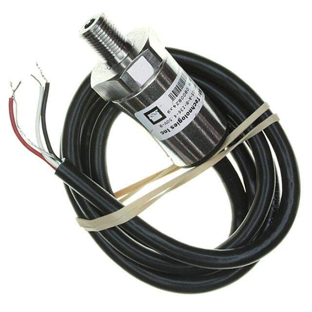
Additional Features n Splashproof shaft seal n Recommended for human/machine interface applications (HMI) n Cable/connector option n Optional bracket EM14 - 14 mm Rotary Optical Encoder w/Switch Part Numbering System E M 1 4 A 0 D - C 2 4 - L 0 3 2 S SWITCH OPTION MODEL NO. DESIGNATOR Code Description EM14 14 mm Rotary Optical Encoder S Push Switch (Standard) H Push Switch (High Force) BUSHING DESIGNATOR N No Switch Code Description A 3/8 " D x 3/8 " L Threaded RESOLUTION (Pulses Per Revolution) C 1/4 " D x 1/4 " L Threaded Code Description R 10 mm D x 9.5 mm L Threaded 08 8 PPR 16 16 PPR DETENT OPTION 32 32 PPR Code Description 64 64 PPR 0 No Detent 1 32 Detents (Available for CABLE/CONNECTOR OPTION 8 or 32 PPR only) Code Description 0 No Cable/Connector ANTI-ROTATION LUG/BRACKET OPTION 6 ” Cable with Female Connector 1 Code Description and stripped/tinned leads A A/R Lug 6 ” Cable with Female Connector 2 B Bracket (No hardware/no cable or on both ends connector) 12 ” Cable with Female Connector 3 D None and stripped/tinned leads 12 ” Cable with Female Connector 4 on both ends SHAFT STYLE (See Outline Drawing for Details) 3 ” Cable with Female Connector and Available w/ 5 stripped/tinned leads Code Description Bushing 1.5 ” Cable with Female Connector and B 1/4 " Dia. Slotted End A 6 stripped/tinned leads C 1/4 " Dia. Flatted End A 2 ” Cable with Female Connector and E 1/8 " Dia. Slotted End C 7 stripped/tinned leads R 6 mm Dia. Slotted End R 5 ” Cable with Female Connector and M 6 mm Dia. Flatted End R 8 stripped/tinned leads SHAFT LENGTH DESIGNATOR For other cable and connector options, please contact the factory. Code Length (FMS) Available w/Bushing 24 3/4 " A, C TERMINAL CONFIGURATION 28 7/8 " A, C Code Description 20 20 mm R L Axial Multi-Purpose Pin 25 25 mm R R Radial Multi-Purpose Pin Specifications are subject to change without notice. Users should verify actual device performance in their specific applications. The products described herein and this document are subject to specific legal disclaimers as set forth on the last page of this document, and at www.bourns.com/docs/legal/disclaimer.pdf.
EM14 - 14 mm Rotary Optical Encoder w/Switch Product Dimensions MOUNTING SURFACE 14.25 (0.561) L 10.03 (.395) 3.18 F 9.53 (.125)TYP. (.375) "L" PIN STYLE 4.76 14.76 (.187) (.581) DIA. 0.457 ± 0.026 (.018 ± .001) 8.00 (.315) METAL SHAFT (SEE TABLE FOR OPTIONS) 1.19 .79 METAL BUSHING (2.0.0882)TYP. TYP.(1.0.7659) R(.047)X(.031)HIGH (SEE TABLE FOR OPTIONS) "R" PIN STYLE "L" PIN STYLE ANTI-ROTATION BOSS 1.52 (OPTIONAL) TYP.(.060) "R" PIN STYLE Shaft / Flat Length Dimensions "A" Style Bushing - Flatted Shafts "R" Style Bushing - Flatted Shafts "C" Style Bushing - Slotted Shafts L L L F (9.3.5735) F (.93.754) (1.0.5620) (6.2.3550) 0.79 4.76 4.42 (.031) 1/4-32 UNEF-2A (.174) (.187) 3/8-32 UNEF-2A M10 x 0.75-6 g SHAFT BUSHING SHAFT LENGTH FLAT LENGTH SHAFT BUSHING SHAFT LENGTH FLAT LENGTH SHAFT BUSHING SHAFT LENGTH DIA. DIA. "L" "F" DIA. DIA. "L" "F" DIA. DIA. "L" 19.05 7.94 20.0 7.0 19.05 6.35 9.52 (.750) (.313) 6.0 10.0 (.787) (.275) 3.17 6.35 (.750) (.250) (.375) 22.22 9.52 (.236) (.394) 25.0 12.0 (.125) (.250) 22.22 (.875) (.375) (.984) (.472) (.875) "A" Style Bushing - Slotted Shafts "R" Style Bushing - Slotted Shafts L L 1.8 9.53 1.8 9.5 (.071) (.375) (.071) (.374) MM DIMENSIONS: (INCHES) 0.99 0.99 (.040) 3/8-32 UNEF-2A (.040) M10 x 0.75-6 g SHAFT BUSHING SHAFT LENGTH SHAFT BUSHING SHAFT LENGTH DIA. DIA. "L" DIA. DIA. "L" 19.05 20.0 6.35 9.52 (.750) 6.0 10.0 (.787) (.250) (.375) 22.22 (.236) (.394) 25.0 (.875) (.984) Specifications are subject to change without notice. Users should verify actual device performance in their specific applications. The products described herein and this document are subject to specific legal disclaimers as set forth on the last page of this document, and at www.bourns.com/docs/legal/disclaimer.pdf. "U" Style Bushing - Slotted Shafts L 1.52 8.0 (.060) (.305) 0.79 (.031) M7 x 0.75-6 g SHAFT BUSHING SHAFT LENGTH DIA. DIA. "L" 20.0 4.0 7.0 (.787) (.158) (.275) 25.0 (.984)
6.0 1.0 Cable Assembly, Connector on One End CONNECTOR x (.236) (.039) x 1.25PITCHRECEPTACLE STRIPPED AND TINNED RIBBON CABLE PIN 1 - 8.0 (.049) 100 % MATTE TIN 6x28 AWG x ( 1. 0 . 24 59 ) PITCH RED STRIPE REF.(.315) FOR(..405178)DIA. PINS 1 2 3 4 5 6 2.9 2.54 ± 0.4 6.0 ± 0.2 (.114) (.100 ± .016) (.236 ± .008) 3.5 ± 0.2 A 8.75 ± 0.2 (.138 ± .008) (.344 ± .008) 6.0 1.0 2 x CONNECTOR x Cable Assembly, Connector on Both Ends (.236) (.039) x 1.25PITCHRECEPTACLE RIBBON CABLE PIN 1 - RED STRIPE (.049) 6x28 AWG x 1 . 2 5 PITCH .457 (.049) FOR(.018)DIA. PINS 3EM31124 -- 124 m mmm RSoMtaDr yT rOipmtimcailn Egn cPoodteern wti/oSmwe654321ittcehr 123456 A Cable/Connector Options 6.0 1.0 Cable Assembly, Connector on One End CONNECTOR (.236)x(.039) HDW. DESCRIPTION “A” DIM. 1.25 NO. x PITCHRECEPTACLE STR10IP0P %ED M AANTDT ET ITNINNED 6x28R AIWBBGO xN ( 1.C 0 . A24 B59 L) PEITCH REPDI NS T1R -I PE REF.(.83.105) FO(R.0(4..40951)78)DIA. PINS H-290-1 CCAOBNLNEE CATSOSREM OBNL BYO, TH ENDS (165.20. 4± ±.1 59.70) 1234 H-290-2 CCAOBNLNEE CATSOSREM OBNL OY,N E END (31024.0.8 ± ± . 159.07) 5 6 2.9 CABLE ASSEMBLY, 304.8 ± 5.0 2.54 ± 0.4 6.0 ± 0.2 (.114) H-290-3 CONNECTOR ON BOTH ENDS (12.0 ± .197) (.100 ± .016) (.236 ± .008) 3.5 ± 0.2 A 8.75 ± 0.2 (.138 ± .008) (.344 ± .008) H-290-4 CABLE ASSEMBLY, 152.4 ± 5.0 CONNECTOR ON ONE END (6.0 ± .197) RIBBON CABLE, 28 AWG, 76.2 ± 5.0 6.0 1.0 H-290-5 CONNECTOR ON ONE END (3.0 ± .197) 2 x CONNECTOR x Cable Assembly, Connector on Both Ends (.236) (.039) x 1.25 PITCHRECEPTACLE RIBBON CABLE, 28 AWG, 38.1 ± 5.0 RIBBON CABLE PIN 1 - RED STRIPE (.049) H-290-6 CONNECTOR ON ONE END (1.5 ± .197) 6x28 AWG x 1 . 2 5 PITCH .457 (.049) FOR(.018)DIA. PINS 654321 123456 HH--229900--87 RRCIOIBBNBBNOOENNC CTCOAABRBLL OEEN,, 2 2O88N AAEWW EGGN,,D (5210.20.78 ± ±± . 1559..007) CONNECTOR ON ONE END (5.0 ± .197) A Terminal Configurations HDW. DESCRIPTION “A” DIM. Radial (shown with optional NmOo.unting bracket) 14.99 ± .13 CABLE ASSEMBLY, 152.4 ± 5.0 Recommended PCB Layout H-290-1 (.590 ± .005) CONNECTOR ON BOTH ENDS (6.0 ± .197) DIA. CLOCKWISE 1.73 ± .10 (H1.54-82.7196 ±0 ± -. 02.2150)CCAOBNLNEE CATSOSREM OBNL OY,N E END (31(021.4.505.98 .±17 ± 6 .± 1 5± 9.. 007.21)50) (.026 8P L±C .0S0.4) CCHHAANNNNEELL ““BA”” H-290-3 CCAOBNLNEE CATSOSREM OBNL BYO, TH ENDS (31024.0.8 ± ± . 159.07) 6 PLCS. D.6I4A. (.73.1807 ±± ..00083) 1 2 (.21.0632 ±± ..03185) (1.76.7167)REF. H-290-4(1.PR0.CE66BCCF03. )AOBNLNEE CAXTS(0OS.10.3RE.558M9 1O)BNWTLH IOYDIC,NE KE END (165.20(7.. 34±.81 ±.701 )59.70)(1.0.2449) CHANGNREOLU N“AD” CHPAONWNEELR “B” (.025) (.10.5520 7P ±L± C ..01S03.5) MOM(EOPNPUTTASIRHOY NO ASNLW)ITCH THICKNESS (.015) REF. MOMENTARY RIBBON CABLE, 28 AWG, 76.2 ± 5.0 SWITCH H-290-5 CONNECTOR ON ONE END (3.0 ± .197) Axial (shown with optional mountinRgIB bBOraNc CkAeBtL)E, 28 AWG, 38.1 ± 5.0 H-290-6 CONNECTOR ON ONE END (1.5 ± .197) 14.99 ± .25 (.590 ± .010) RIBBON CABLE, 28 AWG, 50.8 ± 5.0 H-290-7 Recommended PCB Layout CONNECTOR ON ONE END (2.0 ± .197) 14.61 (.575) RIBBON CABLE, 28 AWG, 127 ± 5.0 DIA. H-290-8 CONNECTOR ON ONE END (5.0 ± .197) 1.73 ± .10 (.068 ± .004) 2 PLCS. REF. DIA. 6.25 ± .08 6.25 .64 1.22 (.246) GROUND CHANNEL “B” (.025) (.246 ± .003) (.048) 6 PLCS. 1.27 ± .13 CHANNEL “A” POWER (.050 ± .005) 10.57 (1.0.6603) MOMENTARY 5 PLCS. 2.49 ± .38 17.17 (.416) REF. SWITCH MM (.098 ± .015) (.676) PCB THICKNESS D IMENSIONS: (INCHES) Specifications are subject to change without notice. Users should verify actual device performance in their specific applications. The products described herein and this document are subject to specific legal disclaimers as set forth on the last page of this document, and at www.bourns.com/docs/legal/disclaimer.pdf.
3EM31124 -- 124 m mmm RSoMtaDr yT rOipmtimcailn Egn cPoodteern wti/oSmweittcehr Electrical Block Diagram Quadrature Output CW – Ground 90 °e ± 45 °e High CHANNEL A Low A Channel A High CHANNEL B Low IRED 180 °e 1 Switch Terminal 1 pulse width 10k Opto ASIC 32 DETENT / 8 PPR 10k CW 2 Switch Terminal CHANNEL A + Power CHANNEL B B Channel B 32 DETENT / 32 PPR Terminal Diagram CW High CHANNEL A Low CHANNEL B High Low CHANNEL "A" GROUND CHANNEL "B" Detent Range NPoosmitiinoanl Detent A12 +B 1. Nominal detent position occurs when both Channel A and B are in low states. 2. Channel A leads Channel B in CW direction and lags in CCW direction. TYP.1.27 POWER (.050) MOMENTARY SWITCH Asia-Pacific: Tel: +886-2 2562-4117 • Email: asiacus@bourns.com EMEA: Tel: +36 88 885 877 • Email: eurocus@bourns.com The Americas: Tel: +1-951 781-5500 • Email: americus@bourns.com www.bourns.com REV. 06/20 Specifications are subject to change without notice. Users should verify actual device performance in their specific applications. The products described herein and this document are subject to specific legal disclaimers as set forth on the last page of this document, and at www.bourns.com/docs/legal/disclaimer.pdf.
Legal Disclaimer Notice This legal disclaimer applies to purchasers and users of Bourns® products manufactured by or on behalf of Bourns, Inc. and its affiliates (collectively, “Bourns”). Unless otherwise expressly indicated in writing, Bourns® products and data sheets relating thereto are subject to change without notice. Users should check for and obtain the latest relevant information and verify that such information is current and complete before placing orders for Bourns® products. The characteristics and parameters of a Bourns® product set forth in its data sheet are based on laboratory conditions, and statements regarding the suitability of products for certain types of applications are based on Bourns’ knowledge of typical requirements in generic applications. The characteristics and parameters of a Bourns® product in a user application may vary from the data sheet characteristics and parameters due to (i) the combination of the Bourns® product with other components in the user’s application, or (ii) the environment of the user application itself. The characteristics and parameters of a Bourns® product also can and do vary in different applications and actual performance may vary over time. Users should always verify the actual performance of the Bourns® product in their specific devices and applications, and make their own independent judgments regarding the amount of additional test margin to design into their device or application to compensate for differences between laboratory and real world conditions. Unless Bourns has explicitly designated an individual Bourns® product as meeting the requirements of a particular industry standard (e.g., ISO/TS 16949) or a particular qualification (e.g., UL listed or recognized), Bourns is not responsible for any failure of an individual Bourns® product to meet the requirements of such industry standard or particular qualification. Users of Bourns® products are responsible for ensuring compliance with safety-related requirements and standards applicable to their devices or applications. Bourns® products are not recommended, authorized or intended for use in nuclear, lifesaving, life-critical or life-sustaining ap- plications, nor in any other applications where failure or malfunction may result in personal injury, death, or severe property or environmental damage. Unless expressly and specifically approved in writing by two authorized Bourns representatives on a case-by-case basis, use of any Bourns® products in such unauthorized applications might not be safe and thus is at the user’s sole risk. Life-critical applications include devices identified by the U.S. Food and Drug Administration as Class III devices and generally equivalent classifications outside of the United States. Bourns expressly identifies those Bourns® standard products that are suitable for use in automotive applications on such products’ data sheets in the section entitled “Applications.” Unless expressly and specifically approved in writing by two authorized Bourns representatives on a case-by-case basis, use of any other Bourns® standard products in an automotive application might not be safe and thus is not recommended, authorized or intended and is at the user’s sole risk. If Bourns expressly identifies a sub-category of automotive application in the data sheet for its standard products (such as infotainment or lighting), such identification means that Bourns has reviewed its standard product and has determined that if such Bourns® standard product is considered for potential use in automotive applications, it should only be used in such sub-category of automotive applications. Any reference to Bourns® standard product in the data sheet as compliant with the AEC-Q standard or “automotive grade” does not by itself mean that Bourns has approved such product for use in an automotive application. Bourns® standard products are not tested to comply with United States Federal Aviation Administration standards generally or any other generally equivalent governmental organization standard applicable to products designed or manufactured for use in aircraft or space applications. Bourns expressly identifies Bourns® standard products that are suitable for use in aircraft or space applications on such products’ data sheets in the section entitled “Applications.” Unless expressly and specifically approved in writing by two authorized Bourns representatives on a case-by-case basis, use of any other Bourns® standard product in an aircraft or space application might not be safe and thus is not recommended, authorized or intended and is at the user’s sole risk. The use and level of testing applicable to Bourns® custom products shall be negotiated on a case-by-case basis by Bourns and the user for which such Bourns® custom products are specially designed. Absent a written agreement between Bourns and the user regarding the use and level of such testing, the above provisions applicable to Bourns® standard products shall also apply to such Bourns® custom products. Users shall not sell, transfer, export or re-export any Bourns® products or technology for use in activities which involve the design, development, production, use or stockpiling of nuclear, chemical or biological weapons or missiles, nor shall they use Bourns® products or technology in any facility which engages in activities relating to such devices. The foregoing restrictions apply to all uses and applications that violate national or international prohibitions, including embargos or international regulations. Further, Bourns® products and Bourns technology and technical data may not under any circumstance be exported or re-exported to countries subject to international sanctions or embargoes. Bourns® products may not, without prior authorization from Bourns and/or the U.S. Government, be resold, transferred, or re-exported to any party not eligible to receive U.S. commodities, software, and technical data. To the maximum extent permitted by applicable law, Bourns disclaims (i) any and all liability for special, punitive, consequential, incidental or indirect damages or lost revenues or lost profits, and (ii) any and all implied warranties, including implied warranties of fitness for particular purpose, non-infringement and merchantability. For your convenience, copies of this Legal Disclaimer Notice with German, Spanish, Japanese, Traditional Chinese and Simplified Chinese bilingual versions are available at: Web Page: http://www.bourns.com/legal/disclaimers-terms-and-policies PDF: http://www.bourns.com/docs/Legal/disclaimer.pdf C1753 05/17/18R