ICGOO在线商城 > CS75ZU2GA152MANKA

 Datasheet下载
- 型号: CS75ZU2GA152MANKA
- 制造商: TDK
- 库位|库存: xxxx|xxxx
- 要求:
| 数量阶梯 | 香港交货 | 国内含税 |
| +xxxx | $xxxx | ¥xxxx |
查看当月历史价格
查看今年历史价格
CS75ZU2GA152MANKA产品简介:
ICGOO电子元器件商城为您提供CS75ZU2GA152MANKA由TDK设计生产,在icgoo商城现货销售,并且可以通过原厂、代理商等渠道进行代购。 提供CS75ZU2GA152MANKA价格参考以及TDKCS75ZU2GA152MANKA封装/规格参数等产品信息。 你可以下载CS75ZU2GA152MANKA参考资料、Datasheet数据手册功能说明书, 资料中有CS75ZU2GA152MANKA详细功能的应用电路图电压和使用方法及教程。
| 参数 | 数值 |
| 产品目录 | |
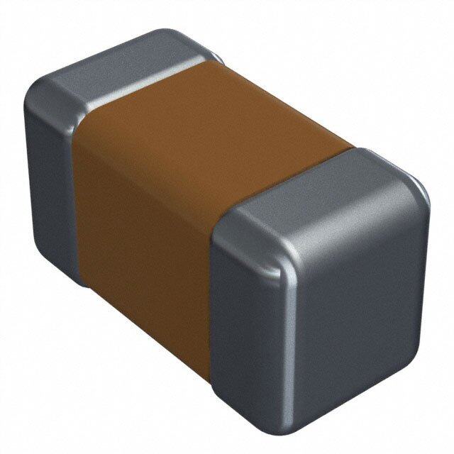
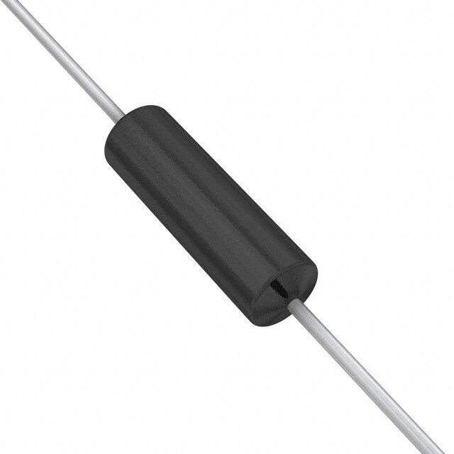
| 描述 | CAP CER 1500PF 300VAC 20% RADIAL瓷片电容器 1500pF X1:440Vac Y2:300Vac Automotive |
| 产品分类 | |
| 品牌 | TDK |
| 产品手册 | |
| 产品图片 |
|
| rohs | 符合RoHS无铅 / 符合限制有害物质指令(RoHS)规范要求 |
| 产品系列 | 陶瓷电容器,瓷片电容器,TDK CS75ZU2GA152MANKACS |
| 数据手册 | |
| 产品型号 | CS75ZU2GA152MANKA |
| 产品 | Ceramic Disc Capacitors |
| 产品种类 | 瓷片电容器 |
| 其它名称 | 445-15876 |
| 包装 | 散装 |
| 厚度 | 7 mm |
| 厚度(最大值) | 0.197"(5.00mm) |
| 商标 | TDK |
| 外壳宽度 | 7 mm |
| 外壳直径 | 8 mm |
| 大小/尺寸 | 0.295" 直径(7.50mm) |
| 安装类型 | 通孔 |
| 容差 | 20 % |
| 封装 | Bulk |
| 封装/外壳 | 径向,圆盘 |
| 工作温度 | -25°C ~ 125°C |
| 工作温度范围 | - 40 C to + 125 C |
| 工厂包装数量 | 1000 |
| 应用 | Automotive |
| 引线形式 | 直形 |
| 引线直径 | 0.6 mm |
| 引线类型 | Vertical Kink |
| 引线间距 | 0.295"(7.50mm) |
| 引线间隔 | 7.5 mm |
| 最大工作温度 | + 125 C |
| 最小工作温度 | - 40 C |
| 标准包装 | 1,000 |
| 温度系数 | Z5U |
| 温度系数/代码 | Z5U |
| 特性 | 高电压 |
| 电压-额定 | 300VAC |
| 电压额定值 | 400 VAC |
| 电压额定值AC | 400 V |
| 电容 | 1500 pF |
| 端接类型 | Radial |
| 等级 | AEC-Q200, X1Y2 |
| 类 | 2 |
| 类型 | High Voltage Ceramic Disc Capacitors |
| 系列 | CS75 |
| 高度-安装(最大值) | - |


PDF Datasheet 数据手册内容提取
C A P A C I T O R S Disc type capacitors with leads Cl Pb Br High voltage ceramic capacitors, automotive grade, safety standard approved RoHS SRVEHCA-CFrHee HaFlroegeen LFereaed CS series FEATURES AEC-Q200 compliant. 1,000 cycles guaranteed under heat shock testing at –55°C to +125°C. For use in Y capacitor for battery chargers of automobile (EV, PHEV). Compliant with IEC and the safety standards of various countries. Withstand voltage is 2,600V AC. Conform to RoHS directive due to lead(Pb) free of lead-wire and internal solder material. Compatible with halogen-free external resin coating. APPLICATION Y capacitor for automotive battery chargers or air conditioners PART NUMBER CONSTRUCTION CS 80 ZU 2GA 222 M A □ K A Series Temperature Nominal Capacitance Grade Lead-wire Application Internal Type Rated voltage name characteristics capacitance tolerance classification type classification code 45 100 10pF J ±5% G Long lead Safety +350 to X1:440V AC For use in SL 2GA A K standard A Halogen-free 65 –1,000ppm/°C Y2:300V AC 221 220pF K ±10% automobiles N Short lead approved 70 B ±10% 472 4,700pF M ±20% V Taping 75 ZU +22, -56% 80 (Z5U) 85 95 11 Please refer to P-3 about the product dimensions. OPERATING TEMPERATURE RANGE Temperature characteristics Operating temperature (°C) Storage temperature (°C) SL –55 to 125 –55 to 125 B –55 to 125 –55 to 125 ZU(Z5U) –55 to 125 –55 to 125 The maximum operating temperature of +125°C includes capacitor self-generated heat of up to 20°C. After capacitor is mounted on board, the storage temperature range is applied. STANDARD LEAD-WIRE SHAPES Dimemsions in mm Symbol G : Bulk/long leads Symbol N : Bulk/short leads Symbol V : Taping D*1 T D*1 T D*1 T 4max. 4max. 4max. 4max. 4max. Vertical kink min. *2 5±1 *2 ø0.65±1±0.05 F +1.516*–0.52 5 2 F F ø0.6±0.05 ø0.6±0.05 TDK’s standard product is vertical kink. TDK recommends short leads for bulk products. *1 Body diameter (D) is reference value if D is smaller than maximum dimension of lead to lead distance (F). *2 Coating on leads shall not extend beyond the bottom of vertical kink. RoHS Directive Compliant Product: See the following for more details. http://product.tdk.com/en/environment/rohs/ Halogen-free: Indicate that Cl content is less than 900ppm, Br content is less than 900ppm, and that the total Cl and Br content is less than 1500ppm. Please be sure to request delivery specifications that provide further details on the features and specifications of the products for proper and safe use. (1/5) Please note that the contents may change without any prior notice due to reasons such as upgrading. 20200917 leaddisc_automotive_cs_en.fm
C A P A C I T O R S Overview of CS series CERTIFIED STATUS OF VARIOUS COUNTRIES Safety Temperature Approval report No.* IEC standard No. Standard No. Sub-class Rated voltage standard characteristics Xiamen BS EN60065 BS EN60384-14 BSI (8.8, 14.2) KM37103 IEC 60384-14 BS EN60384-14 VDE 40017930 SEV 19.0043 SEMKO 1910408 NEMKO EN 60384-14 X1:440V AC P19223652 X1,Y2 DEMKO Y2:300V AC D-04986 SL,B,Z5U FIMKO FI 140177 IMQ IEC 60384-14 V3692 SAA CS6268 CSA CSA-E60384-14 1785515 UL UL60384-14 E37861 CQC IEC 60384-14 CQC10001052862 X1 440V AC SU03047-12006 KTL K60384-14 Y2 300V AC SU03047-12008 * Certificate numbers shall be changed owing to the revisions of the related standards and renewal of certificate. RECOMMENDED FLOW PROFILE Soldering Preheating Natural T2 cooling e ur at er p m e T T: T1 t1 t2 t3 t: Time Preheating Peak Natural cooling Temp. Time Temp. Time Time T1 t1 T2 t2 t3 110°C min. 30 to 60s. 260°C Within 10s. Over 60s. Please be sure to request delivery specifications that provide further details on the features and specifications of the products for proper and safe use. (2/5) Please note that the contents may change without any prior notice due to reasons such as upgrading. 20200917 leaddisc_automotive_cs_en.fm
C A P A C I T O R S CS series MARKINGS Item Markings Description Marking example 1.Series CS CS series 2.Nominal capacitance 10 10pF CS10J 3.Capacitance tolerance J ±5% 4.Rated voltage Eac 440〜X1 X1:440V AC 04 300〜Y2 Y2:300V AC 5.TDK’s trademark Production base code 6.Date code 04 2020.4 7.Applications — For automobile (Marking position is reference.) (underscore below date of production) Year and month of production: last digit of year + month denoted by 1, 2, 3, 4, 5, 6, 7, 8, 9, O (October), N (November), or D (December). The expression has become simplified due to a revision in the standards. RATED VOLTAGE Eac: X1:440V, Y2:300V CAPACITANCE AND DIMENSIONS Dimensions (mm) Part numbers Temperature Capacitance F F Capacitance Bulk/long leads Bulk/short leads Taping characteristics tolerance Dmax. * Tmax. (applied (applied (Symbol: G) (Symbol: N) (Symbol: V) to bulk) to taping) SL 10pF ±5% (7.0) 7.0 7.5±1.5 7.5±0.8 CS45SL2GA100JAGKA CS45SL2GA100JANKA CS45SL2GA100JAVKA SL 15pF ±5% (7.0) 7.0 7.5±1.5 7.5±0.8 CS45SL2GA150JAGKA CS45SL2GA150JANKA CS45SL2GA150JAVKA SL 22pF ±5% (7.0) 7.0 7.5±1.5 7.5±0.8 CS45SL2GA220JAGKA CS45SL2GA220JANKA CS45SL2GA220JAVKA SL 33pF ±5% (7.0) 7.0 7.5±1.5 7.5±0.8 CS45SL2GA330JAGKA CS45SL2GA330JANKA CS45SL2GA330JAVKA SL 47pF ±5% (8.0) 7.0 7.5±1.5 7.5±0.8 CS45SL2GA470JAGKA CS45SL2GA470JANKA CS45SL2GA470JAVKA SL 68pF ±5% 9.0 7.0 7.5±1.5 7.5±0.8 CS45SL2GA680JAGKA CS45SL2GA680JANKA CS45SL2GA680JAVKA B 100pF ±10% (7.0) 7.0 7.5±1.5 7.5±0.8 CS65-B2GA101KAGKA CS65-B2GA101KANKA CS65-B2GA101KAVKA B 150pF ±10% (7.0) 7.0 7.5±1.5 7.5±0.8 CS65-B2GA151KAGKA CS65-B2GA151KANKA CS65-B2GA151KAVKA B 220pF ±10% (7.0) 7.0 7.5±1.5 7.5±0.8 CS65-B2GA221KAGKA CS65-B2GA221KANKA CS65-B2GA221KAVKA B 330pF ±10% (7.5) 7.0 7.5±1.5 7.5±0.8 CS70-B2GA331KAGKA CS70-B2GA331KANKA CS70-B2GA331KAVKA B 470pF ±10% 9.0 7.0 7.5±1.5 7.5±0.8 CS75-B2GA471KAGKA CS75-B2GA471KANKA CS75-B2GA471KAVKA B 680pF ±10% 9.5 7.0 7.5±1.5 7.5±0.8 CS85-B2GA681KAGKA CS85-B2GA681KANKA CS85-B2GA681KAVKA Z5U 1,000pF ±20% (7.0) 7.0 7.5±1.5 7.5±0.8 CS65ZU2GA102MAGKA CS65ZU2GA102MANKA CS65ZU2GA102MAVKA Z5U 1,500pF ±20% (8.0) 7.0 7.5±1.5 7.5±0.8 CS75ZU2GA152MAGKA CS75ZU2GA152MANKA CS75ZU2GA152MAVKA Z5U 2,200pF ±20% 9.5 7.0 7.5±1.5 7.5±0.8 CS80ZU2GA222MAGKA CS80ZU2GA222MANKA CS80ZU2GA222MAVKA Z5U 3,300pF ±20% 12.0 7.0 7.5±1.5 7.5±0.8 CS95ZU2GA332MAGKA CS95ZU2GA332MANKA CS95ZU2GA332MAVKA Z5U 4,700pF ±20% 13.5 7.0 7.5±1.5 7.5±0.8 CS11ZU2GA472MAGKA CS11ZU2GA472MANKA CS11ZU2GA472MAVKA The values in parentheses "( )" are reference values. Click the part number for details. Reference values are applied to bulk products. (cid:129) Please refer to p-4 about the taping dimemsions. (cid:129) For more information about products with other capacitance or other data, please contact us. Please be sure to request delivery specifications that provide further details on the features and specifications of the products for proper and safe use. (3/5) Please note that the contents may change without any prior notice due to reasons such as upgrading. 20200917 leaddisc_automotive_cs_en.fm
C A P A C I T O R S CS series TAPING DIMENSIONS P P2 D*1 T h h A H0 W2 *2C S P1 F H0 W1 L W0 W t P0 D0 ød Item Symbols Dimensions (mm) Remarks *1 Body diameter (D) is reference value if D is smaller than maximum Body diameter D Refer to P-3 dimension of lead to lead distance (F). Body thickness T Refer to P-3 Lead-wire diameter ød 0.6±0.05 Pitch of component P 15.0±1.0 Including the slant of body Feed hole pitch P0 15.0±0.3 Excepting the tape splicing part Feed hole center to lead-wire P1 3.75±0.7 Feed hole center to component center P2 7.5±1.3 Including the slanting body due to bending lead-wire Lead-to lead distance F 7.5±0.8 Measuring point is bottom kink Component alignment h 0±2.0 Including the slanting body due to bending lead-wire Carrier tape width W 18.0+1.0,–0.5 Adhesive tape width W0 10.0 Min. Hole position W1 9.0±0.5 Adhesive tape position W2 4.0 Max. Adhesive tape do not stick out the tape Bottom of kink from tape center H0 16.0+1.5,–0.5 Lead-wire protrusion 1.0 Max. Feed hole diameter D0 4.0±0.2 Carrier tape thickness t 0.6±0.3 Including adhesive tape (Including adhesive tape) Length of snipped lead-wire L 11.0 Max. Coating on lead-wire C 4.0 Max. *2 Coating on leads shall not extend beyond the bottom of vertical kink. Height of kink A 4.0 Max. Measuring point is bottom kink Spring action S 2.0 Max. AMMO PACK INNER BOX SIZE PACKAGE QUANTITY Package quantity Type Bulk (pieces / bag) Taping (pieces / box) CS 1000 1000 ax. m 0 2 3 340max. 60max. Dimensions in mm Please be sure to request delivery specifications that provide further details on the features and specifications of the products for proper and safe use. (4/5) Please note that the contents may change without any prior notice due to reasons such as upgrading. 20200917 leaddisc_automotive_cs_en.fm
C A P A C I T O R S REMINDERS FOR USING THESE PRODUCTS Before using these products, be sure to request the delivery specifications. SAFETY REMINDERS Please pay sufficient attention to the warnings for safe designing when using this products. REMINDERS Do not use or store in locations where there are conditions such as gas corrosion (salt, acid, alkali, etc.). Before soldering, be sure to preheat components. The preheating temperature should be set so that the temperature difference between the solder temperature and product temperature does not exceed 150°C. Soldering corrections after mounting should be within the range of the conditions determined in the specifications. If overheated, a short circuit, performance deterioration, or lifespan shortening may occur. Self heating (temperature increase) occurs when the power is turned ON, so the tolerance should be sufficient for the set thermal design. Do not use for a purpose outside of the contents regulated in the delivery specifications. The products listed on this catalog are intended for use in automotive electronic equipment under a normal operation and use condi- tion. The products are not designed or warranted to meet the requirements of the applications listed below, whose performance and/or qual- ity require a more stringent level of safety or reliability, or whose failure, malfunction or trouble could cause serious damage to society, person or property. If you intend to use the products in the applications listed below or if you have special requirements exceeding the range or conditions set forth in the each catalog, please contact us. (1) Aerospace/aviation equipment (8) Public information-processing equipment (2) Transportation equipment (electric trains, ships, etc.) (9) Military equipment (3) Medical equipment (10) Electric heating apparatus, burning equipment (4) Power-generation control equipment (11) Disaster prevention/crime prevention equipment (5) Atomic energy-related equipment (12) Safety equipment (6) Seabed equipment (13) Other applications that are not considered general-purpose (7) Transportation control equipment applications Please refer to the guideline of notabilia for fixed ceramic capacitors issued by JEITA(Japan Electronics and Information Technology Association, EIAJ RCR-2335). This guideline describes general precautions* for using fixed ceramic capacitors. Please carefully confirm it and use capacitors safely. * Items for check, explanation/reason/concrete example and failure examples, etc. When designing your equipment even for general-purpose applications, you are kindly requested to take into consideration securing pro- tection circuit/device or providing backup circuits in your equipment. Please be sure to request delivery specifications that provide further details on the features and specifications of the products for proper and safe use. (5/5) Please note that the contents may change without any prior notice due to reasons such as upgrading. 20200917 leaddisc_automotive_cs_en.fm