 Datasheet下载
- 型号: CBR06C200JAGAC
- 制造商: Kemet
- 库位|库存: xxxx|xxxx
- 要求:
| 数量阶梯 | 香港交货 | 国内含税 |
| +xxxx | $xxxx | ¥xxxx |
查看当月历史价格
查看今年历史价格
CBR06C200JAGAC产品简介:
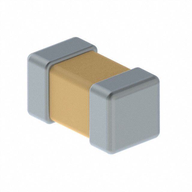
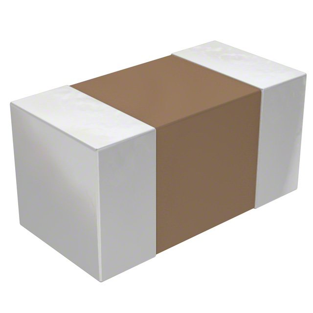
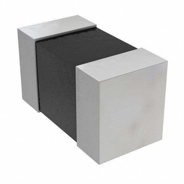
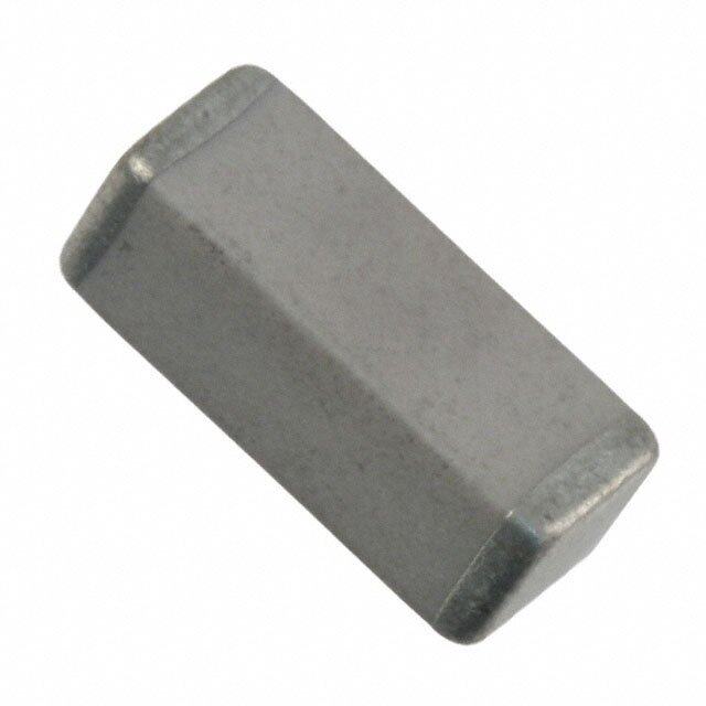
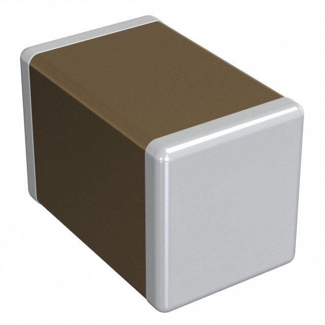
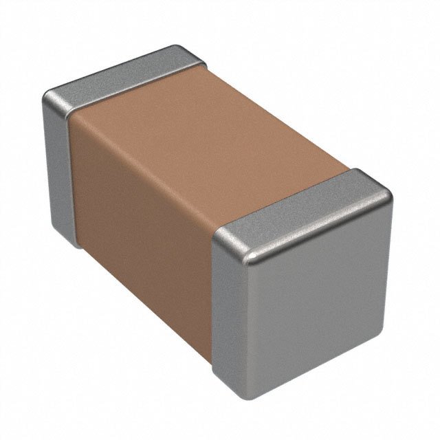
ICGOO电子元器件商城为您提供CBR06C200JAGAC由Kemet设计生产,在icgoo商城现货销售,并且可以通过原厂、代理商等渠道进行代购。 CBR06C200JAGAC价格参考。KemetCBR06C200JAGAC封装/规格:陶瓷电容器, 20pF ±5% 250V 陶瓷电容器 C0G,NP0 0603(1608 公制)。您可以下载CBR06C200JAGAC参考资料、Datasheet数据手册功能说明书,资料中有CBR06C200JAGAC 详细功能的应用电路图电压和使用方法及教程。
KEMET品牌的陶瓷电容器型号CBR06C200JAGAC是一款多层陶瓷电容器(MLCC),其主要应用场景包括以下方面:

1. 电源滤波:该电容器适用于电源电路中的滤波功能,能够有效抑制电源噪声,确保电路的稳定运行。例如,在开关电源、DC-DC转换器和稳压电路中,可用来平滑电压波动。

2. 信号耦合与解耦:在高频信号传输中,CBR06C200JAGAC可用于信号耦合或解耦,帮助去除不需要的直流成分或交流干扰,适用于通信设备、音频处理和射频电路。

3. 高频旁路:由于其低ESR(等效串联电阻)特性,这款电容器适合用作高频旁路电容,为高速数字电路(如微控制器、FPGA)提供稳定的电源支持,减少高频噪声对系统的影响。

4. 谐振与匹配电路:在射频和无线通信领域,CBR06C200JAGAC可用于构建谐振电路或阻抗匹配网络,以优化信号传输效率和质量。

5. 时序电路:在需要精确时间控制的电路中(如RC振荡器或定时电路),该电容器可以与其他元件配合使用,实现特定的时间常数。

6. 汽车电子:KEMET的陶瓷电容器以其高可靠性和稳定性著称,CBR06C200JAGAC也可用于汽车电子系统中,如车载信息娱乐系统、传感器接口和引擎控制单元(ECU)。

总结来说,CBR06C200JAGAC凭借其小体积、高频率特性和良好的温度稳定性,广泛应用于消费电子、工业控制、通信设备以及汽车电子等领域,满足各种复杂环境下的电路需求。
| 参数 | 数值 |
| 产品目录 | |
| 描述 | CAP CER 20PF 250V 5% NP0 0603 |
| 产品分类 | |
| 品牌 | Kemet |
| 数据手册 | 点击此处下载产品Datasheethttp://capacitoredge.kemet.com/capedge2/DataSheet?pn=CBR06C200JAGAC |
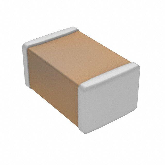
| 产品图片 |
|
| 产品型号 | CBR06C200JAGAC |
| rohs | 无铅 / 符合限制有害物质指令(RoHS)规范要求 |
| 产品系列 | CBR |
| 产品培训模块 | http://www.digikey.cn/PTM/IndividualPTM.page?site=cn&lang=zhs&ptm=25569http://www.digikey.cn/PTM/IndividualPTM.page?site=cn&lang=zhs&ptm=26226 |
| 其它名称 | 339-8675-6 |
| 包装 | Digi-Reel® |
| 厚度(最大值) | 0.034"(0.87mm) |
| 大小/尺寸 | 0.063" 长 x 0.031" 宽(1.60mm x 0.80mm) |
| 安装类型 | 表面贴装,MLCC |
| 容差 | ±5% |
| 封装/外壳 | 0603(1608 公制) |
| 工作温度 | -55°C ~ 125°C |
| 应用 | RF,微波,高频 |
| 引线形式 | - |
| 引线间距 | - |
| 标准包装 | 1 |
| 温度系数 | C0G,NP0 |
| 特性 | 高 Q 值,低损耗 |
| 特色产品 | http://www.digikey.com/product-highlights/cn/zh/kemet-cbr-rf-ceramics/1028http://www.digikey.cn/product-highlights/zh/hiqcbr-series/50483 |
| 电压-额定 | 250V |
| 电容 | 20pF |
| 等级 | - |
| 高度-安装(最大值) | - |


- 商务部:美国ITC正式对集成电路等产品启动337调查
- 曝三星4nm工艺存在良率问题 高通将骁龙8 Gen1或转产台积电
- 太阳诱电将投资9.5亿元在常州建新厂生产MLCC 预计2023年完工
- 英特尔发布欧洲新工厂建设计划 深化IDM 2.0 战略
- 台积电先进制程称霸业界 有大客户加持明年业绩稳了
- 达到5530亿美元!SIA预计今年全球半导体销售额将创下新高
- 英特尔拟将自动驾驶子公司Mobileye上市 估值或超500亿美元
- 三星加码芯片和SET,合并消费电子和移动部门,撤换高东真等 CEO
- 三星电子宣布重大人事变动 还合并消费电子和移动部门
- 海关总署:前11个月进口集成电路产品价值2.52万亿元 增长14.8%


PDF Datasheet 数据手册内容提取
Surface Mount Multilayer Ceramic Capacitors (SMD MLCCs) for High Power Applications HiQ-CBR Series, C0G Dielectric, Low ESR 6.3 – 500 VDC, 1 MHz – 50 GHz (RF & Microwave) Overview KEMET’s CBR Series surface mount multilayer ceramic capacitors (MLCCs) in C0G dielectric feature a robust and exceptionally stable copper electrode dielectric system that offers excellent low loss performance (high Q). These reference to ambient temperature. Capacitance change is devices provide extremely low ESR and high self-resonance limited to ±30 ppm/ºC from −55°C to +125°C. characteristics, and are well-suited for resonant circuit applications or those where Q and stability of capacitance CBR Series devices are suitable for many circuit applications characteristics are required. CBR Series capacitors including RF power amplifiers, mixers, oscillators, low noise exhibit no change in capacitance with respect to time and amplifiers, filter networks, antenna tuning, timing circuits, voltage, and boast a negligible change in capacitance with delay lines, and MRI imaging coils. Benefits • High Q and low ESR • High SRF • High thermal stability • 1 MHz to 50 GHz frequency range • Operating temperature range of −55°C to +125°C • Base metal electrode (BME) dielectric system • Pb-free and RoHS compliant • 0201, 0402, 0603, and 0805 case sizes (inches) • DC voltage ratings of 6.3 V, 10 V, 25 V, 50 V, 100 V, 200 V, 250 V, and 500 V • Capacitance offerings ranging from 0.1 pF up to 100 pF Ordering Information CBR 02 C 330 F 9 G A C Rated Packaging/ Case Size Specification/ Capacitance Capacitance Termination Series Voltage Dielectric Termination Finish Grade (L"x W") Series Code (pF) Tolerance Style (VDC) (C-Spec)1 CBR 02 = 0201 C = Standard Two significant digits A = ±0.05 pF 9 = 6.3 V G = C0G A = N/A C = 100% Matte Sn Blank = 04 = 0402 + number of zeros B = ±0.1 pF 8 = 10 V 7" Reel 06 = 0603 Use 9 for 1.0 – 9.9 pF C = ±0.25 pF 3 = 25 V Unmarked 08 = 0805 Use 8 for 0.1 – 0.99 pF D = ±0.5 pF 5 = 50 V e.g., 2.2 pF = 229 F = ±1% 1 = 100 V e.g., 0.5 pF = 508 G = ±2% 2 = 200 V J = ±5% A = 250 V C = 500 V 1 When ordering CBR Series devices, a "suffix" or "C-Spec" is not required to indicate a 7" reel packaging option. CBR devices are only available and shipped on 7" reels (paper tape). Bulk bag and cassette packaging options are not available. Please contact KEMET if you have a specific, non-standard packaging requirement. One world. One KEMET © KEMET Electronics Corporation • P.O. Box 5928 • Greenville, SC 29606 • 864-963-6300 • www.kemet.com C1030_C0G_CBR • 8/1/2016 1
Surface Mount Multilayer Ceramic Capacitors (SMD MLCCs) for High Power Applications HiQ-CBR Series, C0G Dielectric, Low ESR 6.3 – 500 VDC, 1 MHz – 50 GHz (RF & Microwave) Benefits cont'd • Available capacitance tolerances of ±0.05 pF, ±0.1 pF, • Negligible capacitance change with respect to temperature ±0.25 pF, ±0.5 pF, ±1%, ±2%, and ±5% • No capacitance decay with time • No piezoelectric noise • Non-polar device, minimizing installation concerns • No capacitance change with respect to applied rated DC • 100% pure matte tin-plated termination finish allowing for voltage excellent solderability Applications Typical applications include critical timing, tuning, bypass, coupling, feedback, filtering, impedance matching and DC blocking. Field applications include wireless and cellular base stations, wireless LAN, subscriber-based wireless services, wireless broadcast equipment, satellite communications, RF power amplifier (PA) modules, filters, voltage-controlled oscillators (VCOs), PAs, matching networks, RF modules, satellite communications and medical electronics. Qualification RF and microwave products are subject to internal qualification. Details regarding test methods and conditions are referenced in Table 4, Performance & Reliability. Environmental Compliance Pb-free and RoHS compliant. © KEMET Electronics Corporation • P.O. Box 5928 • Greenville, SC 29606 • 864-963-6300 • www.kemet.com C1030_C0G_CBR • 8/1/2016 2
Surface Mount Multilayer Ceramic Capacitors (SMD MLCCs) for High Power Applications HiQ-CBR Series, C0G Dielectric, Low ESR 6.3 – 500 VDC, 1 MHz – 50 GHz (RF & Microwave) Dimensions – Millimeters (Inches) W L T B Case Case L W T B Mounting Size (in.) Size (mm) Length Width Thickness Bandwidth Technique 0.60±0.03 0.30±0.03 0.30±0.03 0.15±0.05 0201 0603 (0.024±0.001) (0.012±0.001) (0.012±0.001) (0.006±0.002) Solder Reflow Only 1.00±0.05 0.50±0.05 0.50±0.05 0.25+0.05/−0.10 0402 1005 (0.040±0.002) (0.020±0.002) (0.020±0.002) (0.010+0.002/−0.004) 1.60±0.10 0.80±0.10 0.80±0.07 0.40±0.15 0603 1608 (0.063±0.004) (0.031±0.004) (0.031±0.003) (0.016±0.006) Solder Wave 2.00±0.20 1.25±0.20 0.85±0.10 0.50±0.20 or Solder Reflow 0805 2012 (0.079±0.008) (0.049±0.008) (0.031±0.004) (0.020±0.008) Electrical Parameters/Characteristics Item Parameters/Characteristics Operating Temperature Range: −55°C to +125°C Capacitance Change with Reference to 0 ±30 ppm/ºC (0 ±60 ppm/ºC for 0201 case size product ≥ 22 pF) +25°C and 0 VDC Applied (TCC): Aging Rate (Maximum % Capacitance Loss/Decade Hour): 0% See Dielectric Withstanding Voltage Table 1Dielectric Withstanding Voltage (DWV): (5±1 seconds and charge/discharge not exceeding 50 mA) ≥ 1,000 for capacitance values ≥ 30 pF 2Quality Factor (Q): ≥ 400 + 20ºC for capacitance values < 30 pF 3Insulation Resistance (IR) Limit at 25°C: 10 GΩ minimum (rated voltage applied for 120±5 seconds) 1 DWV is the voltage a capacitor can withstand (survive) for a short period of time. It exceeds the nominal and continuous working voltage of the capacitor. 2 Capacitance and quality factor (Q) measured at 1 MHz ±100 kHz and 1.0 ±0.2 Vrms. 3 To obtain IR limit, divide MΩ-µF value by the capacitance and compare to GΩ limit. Select the lower of the two limits. Note: When measuring capacitance it is important to ensure the set voltage level is held constant. The HP4284 & Agilent E4980 have a feature known as Automatic Level Control (ALC). The ALC feature should be switched to "ON." © KEMET Electronics Corporation • P.O. Box 5928 • Greenville, SC 29606 • 864-963-6300 • www.kemet.com C1030_C0G_CBR • 8/1/2016 3
Surface Mount Multilayer Ceramic Capacitors (SMD MLCCs) for High Power Applications HiQ-CBR Series, C0G Dielectric, Low ESR 6.3 – 500 VDC, 1 MHz – 50 GHz (RF & Microwave) Dielectric Withstanding Voltage Table Rated Voltage (VDC) ≤100 V 200 V 250 V 500 V DWV 250% 200% 200% 150% Electrical Characteristics SRF (MHz) vs. Cap (pF) 100,000 0201 0402 10,000 0603 ) z H 0805 M ( F R S 1,000 100 0.1 1 10 100 Cap (pF) © KEMET Electronics Corporation • P.O. Box 5928 • Greenville, SC 29606 • 864-963-6300 • www.kemet.com C1030_C0G_CBR • 8/1/2016 4
Surface Mount Multilayer Ceramic Capacitors (SMD MLCCs) for High Power Applications HiQ-CBR Series, C0G Dielectric, Low ESR 6.3 – 500 VDC, 1 MHz – 50 GHz (RF & Microwave) Electrical Characteristics cont'd ESR vs. Frequency 0402 Q vs. Frequency 0402 1 10,000 1.8pF 1,000 1.8pF ms) 4.7pF 4.7pF Oh 0.1 10pF 10pF R ( 18pF Q 100 18pF S 22pF E 22pF 10 0.01 100 1,000 10,000 1 Freq (MHz) 100 1,000 10,000 Freq (MHz) ESR vs. Frequency 0603 Q vs. Frequency 0603 1 10,000 2.2pF 1,000 ) 2.2pF s 4.7pF m 4.7pF h 10pF R (O 0.1 10pF Q100 20pF S 20pF 47pF E 47pF 10 0.01 1 100 1,000 10,000 100 1,000 10,000 Freq (MHz) Freq (MHz) ESR vs. Frequency 0805 Q vs. Frequency 0805 1 10,000 2.2pF 1,000 2.2pF 10pF ) s m 10pF 33pF Oh 0.1 33pF Q 100 47pF ( R 47pF 100pF S E 100pF 10 0.01 1 100 1,000 10,000 100 1,000 10,000 Freq (MHz) Freq (MHz) © KEMET Electronics Corporation • P.O. Box 5928 • Greenville, SC 29606 • 864-963-6300 • www.kemet.com C1030_C0G_CBR • 8/1/2016 5
Surface Mount Multilayer Ceramic Capacitors (SMD MLCCs) for High Power Applications HiQ-CBR Series, C0G Dielectric, Low ESR 6.3 – 500 VDC, 1 MHz – 50 GHz (RF & Microwave) Table 1 – CBR Series, Capacitance Range Waterfall Case Size – Inches (mm) 0201 (0603) 0402 (1005) 0603 (1608) 0805 (2012) mm 0.60 ± 0.03 1.00 ± 0.05 1.60 ± 0.10 2.00 ± 0.20 Length (Inches) (0.024 ± 0.001) (0.040 ± 0.002) (0.063 ± 0.004) (0.079 ± 0.008) mm 0.30 ± 0.03 0.50 ± 0.05 0.80 ± 0.10 1.25 ± 0.20 Width (Inches) (0.012 ± 0.001) (0.020 ± 0.002) (0.031 ± 0.004) (0.049 ± 0.008) mm 0.30 ± 0.03 0.50 ± 0.05 0.80 ± 0.07 0.85 ± 0.10 Thickness (Inches) (0.012 ± 0.001) (0.020 ± 0.002) (0.031 ± 0.003) (0.031 ± 0.004) mm 0.15 ± 0.05 0.25 + 0.05 / -0.10 0.40 ± 0.15 0.50 ± 0.20 Bandwidth (Inches) (0.006 ± 0.002) (0.010 + 0.002 / -0.004) (0.016 ± 0.006) (0.020 ± 0.008) Rated Voltage (VDC) 6.3 10 25 50 25 50 100 200 50 100 250 50 100 250 500 Voltage Code 9 8 3 5 3 5 1 2 5 1 A 5 1 A C Capacitance Capacitance Capacitance Code (Available Capacitance) Tolerance 0.1 pF 108* 108* 108* 108* 108 108 108* 108* 0.2 pF A = ±0.05 pF 208 208 208 208 208 208 208 208 0.3 pF B = ±0.1 pF 308 308 308 308 308 308 308 308 308 308 308 308 308 308 308 0.4 pF 408 408 408 408 408 408 408 408 408 408 408 408 408 408 408 0.5 pF 508 508 508 508 508 508 508 508 508 508 508 508 508 508 508 0.6 pF 608 608 608 608 608 608 608 608 608 608 608 608 608 608 608 0.7 pF 708 708 708 708 708 708 708 708 708 708 708 708 708 708 708 0.8 pF 808 808 808 808 808 808 808 808 808 808 808 808 808 808 808 0.9 pF 908 908 908 908 908 908 908 908 908 908 908 908 908 908 908 1.0 pF 109 109 109 109 109 109 109 109 109 109 109 109 109 109 109 1.1 pF 119 119 119 119 119 119 119 119 119 119 119 119 119 119 119 1.2 pF 129 129 129 129 129 129 129 129 129 129 129 129 129 129 129 1.3 pF 139 139 139 139 139 139 139 139 139 139 139 139 139 139 139 1.4 pF 149 149 149 149 149 149 149 149 149 149 149 149 149 149 149 1.5 pF 159 159 159 159 159 159 159 159 159 159 159 159 159 159 159 1.6 pF 169 169 169 169 169 169 169 169 169 169 169 169 169 169 169 1.7 pF 179 179 179 179 179 179 179 179 179 179 179 179 179 179 179 1.8 pF 189 189 189 189 189 189 189 189 189 189 189 189 189 189 189 1.9 pF 199 199 199 199 199 199 199 199 199 199 199 199 199 199 199 2.0 pF 209 209 209 209 209 209 209 209 209 209 209 209 209 209 209 2.1 pF 219 219 219 219 219 219 219 219 219 219 219 219 219 219 219 2.2 pF 229 229 229 229 229 229 229 229 229 229 229 229 229 229 229 2.3 pF 239 239 239 239 239 239 239 239 239 239 239 239 239 239 239 2.4 pF 249 249 249 249 249 249 249 249 249 249 249 249 249 249 249 2.5 pF 259 259 259 259 259 259 259 259 259 259 259 259 259 259 259 2.6 pF A = ±0.05 pF 269 269 269 269 269 269 269 269 269 269 269 269 269 269 269 2.7 pF B = ±0.1 pF 279 279 279 279 279 279 279 279 279 279 279 279 279 279 279 2.8 pF C = ±0.25 pF 289 289 289 289 289 289 289 289 289 289 289 289 289 289 289 2.9 pF 299 299 299 299 299 299 299 299 299 299 299 299 299 299 299 3.0 pF 309 309 309 309 309 309 309 309 309 309 309 309 309 309 309 3.1 pF 319 319 319 319 319 319 319 319 319 319 319 319 319 319 319 3.2 pF 329 329 329 329 329 329 329 329 329 329 329 329 329 329 329 3.3 pF 339 339 339 339 339 339 339 339 339 339 339 339 339 339 339 3.4 pF 349 349 349 349 349 349 349 349 349 349 349 349 349 349 349 3.5 pF 359 359 359 359 359 359 359 359 359 359 359 359 359 359 359 3.6 pF 369 369 369 369 369 369 369 369 369 369 369 369 369 369 369 3.7 pF 379 379 379 379 379 379 379 379 379 379 379 379 379 379 379 3.8 pF 389 389 389 389 389 389 389 389 389 389 389 389 389 389 389 3.9 pF 399 399 399 399 399 399 399 399 399 399 399 399 399 399 399 4.0 pF 409 409 409 409 409 409 409 409 409 409 409 409 409 409 409 4.1 pF 419 419 419 419 419 419 419 419 419 419 419 419 419 419 419 4.2 pF 429 429 429 429 429 429 429 429 429 429 429 429 429 429 429 4.3 pF 439 439 439 439 439 439 439 439 439 439 439 439 439 439 439 4.4 pF 449 449 449 449 449 449 449 449 449 449 449 449 449 449 449 4.5 pF 459 459 459 459 459 459 459 459 459 459 459 459 459 459 459 4.6 pF 469 469 469 469 469 469 469 469 469 469 469 469 469 469 469 4.7 pF 479 479 479 479 479 479 479 479 479 479 479 479 479 479 479 4.8 pF 489 489 489 489 489 489 489 489 489 489 489 489 489 489 489 4.9 pF 499 499 499 499 499 499 499 499 499 499 499 499 499 499 499 Rated Voltage (VDC) 6.3 10 25 50 25 50 100 200 50 100 250 50 100 250 500 Voltage Code 9 8 3 5 3 5 1 2 5 1 A 5 1 A C *Available only in "B" ( ±0.1pF) capacitance tolerance. © KEMET Electronics Corporation • P.O. Box 5928 • Greenville, SC 29606 • 864-963-6300 • www.kemet.com C1030_C0G_CBR • 8/1/2016 6
Surface Mount Multilayer Ceramic Capacitors (SMD MLCCs) for High Power Applications HiQ-CBR Series, C0G Dielectric, Low ESR 6.3 – 500 VDC, 1 MHz – 50 GHz (RF & Microwave) Table 1 – CBR Series, Capacitance Range Waterfall cont'd Case Size – Inches (mm) 0201 (0603) 0402 (1005) 0603 (1608) 0805 (2012) mm 0.60 ± 0.03 1.00 ± 0.05 1.60 ± 0.10 2.00 ± 0.20 Length (Inches) (0.024 ± 0.001) (0.040 ± 0.002) (0.063 ± 0.004) (0.079 ± 0.008) mm 0.30 ± 0.03 0.50 ± 0.05 0.80 ± 0.10 1.25 ± 0.20 Width (Inches) (0.012 ± 0.001) (0.020 ± 0.002) (0.031 ± 0.004) (0.049 ± 0.008) mm 0.30 ± 0.03 0.50 ± 0.05 0.80 ± 0.07 0.85 ± 0.10 Thickness (Inches) (0.012 ± 0.001) (0.020 ± 0.002) (0.031 ± 0.003) (0.031 ± 0.004) mm 0.15 ± 0.05 0.25 + 0.05 / -0.10 0.40 ± 0.15 0.50 ± 0.20 Bandwidth (Inches) (0.006 ± 0.002) (0.010 + 0.002 / -0.004) (0.016 ± 0.006) (0.020 ± 0.008) Rated Voltage (VDC) 6.3 10 25 50 25 50 100 200 50 100 250 50 100 250 500 Voltage Code 9 8 3 5 3 5 1 2 5 1 A 5 1 A C Capacitance Capacitance Capacitance Code (Available Capacitance) Tolerance A = ±0.05 pF 5.0 pF B = ±0.1 pF 509 509 509 509 509 509 509 509 509 509 509 509 509 509 509 C = ±0.25 pF 5.1 pF 519 519 519 519 519 519 519 519 519 519 519 519 519 519 519 5.2 pF 529 529 529 529 529 529 529 529 529 529 529 529 529 529 529 5.3 pF 539 539 539 539 539 539 539 539 539 539 539 539 539 539 539 5.4 pF 549 549 549 549 549 549 549 549 549 549 549 549 549 549 549 5.5 pF 559 559 559 559 559 559 559 559 559 559 559 559 559 559 559 5.6 pF 569 569 569 569 569 569 569 569 569 569 569 569 569 569 569 5.7 pF 579 579 579 579 579 579 579 579 579 579 579 579 579 579 579 5.8 pF 589 589 589 589 589 589 589 589 589 589 589 589 589 589 589 5.9 pF 599 599 599 599 599 599 599 599 599 599 599 599 599 599 599 6.0 pF 609 609 609 609 609 609 609 609 609 609 609 609 609 609 609 6.1 pF 619 619 619 619 619 619 619 619 619 619 619 619 619 619 619 6.2 pF 629 629 629 629 629 629 629 629 629 629 629 629 629 629 629 6.3 pF 639 639 639 639 639 639 639 639 639 639 639 639 639 639 639 6.4 pF 649 649 649 649 649 649 649 649 649 649 649 649 649 649 649 6.5 pF 659 659 659 659 659 659 659 659 659 659 659 659 659 659 659 6.6 pF 669 669 669 669 669 669 669 669 669 669 669 669 669 669 669 6.7 pF 679 679 679 679 679 679 679 679 679 679 679 679 679 679 679 6.8 pF 689 689 689 689 689 689 689 689 689 689 689 689 689 689 689 6.9 pF 699 699 699 699 699 699 699 699 699 699 699 699 699 699 699 7.0 pF 709 709 709 709 709 709 709 709 709 709 709 709 709 709 709 7.1 pF 719 719 719 719 719 719 719 719 719 719 719 719 719 719 719 7.2 pF B = ±0.1 pF 729 729 729 729 729 729 729 729 729 729 729 729 729 729 729 7.3 pF C = ±0.25 pF 739 739 739 739 739 739 739 739 739 739 739 739 739 739 739 7.4 pF D = ±0.5 pF 749 749 749 749 749 749 749 749 749 749 749 749 749 749 749 7.5 pF 759 759 759 759 759 759 759 759 759 759 759 759 759 759 759 7.6 pF 769 769 769 769 769 769 769 769 769 769 769 769 769 769 769 7.7 pF 779 779 779 779 779 779 779 779 779 779 779 779 779 779 779 7.8 pF 789 789 789 789 789 789 789 789 789 789 789 789 789 789 789 7.9 pF 799 799 799 799 799 799 799 799 799 799 799 799 799 799 799 8.0 pF 809 809 809 809 809 809 809 809 809 809 809 809 809 809 809 8.1 pF 819 819 819 819 819 819 819 819 819 819 819 819 819 819 819 8.2 pF 829 829 829 829 829 829 829 829 829 829 829 829 829 829 829 8.3 pF 839 839 839 839 839 839 839 839 839 839 839 839 839 839 839 8.4 pF 849 849 849 849 849 849 849 849 849 849 849 849 849 849 849 8.5 pF 859 859 859 859 859 859 859 859 859 859 859 859 859 859 859 8.6 pF 869 869 869 869 869 869 869 869 869 869 869 869 869 869 869 8.7 pF 879 879 879 879 879 879 879 879 879 879 879 879 879 879 879 8.8 pF 889 889 889 889 889 889 889 889 889 889 889 889 889 889 889 8.9 pF 899 899 899 899 899 899 899 899 899 899 899 899 899 899 899 9.0 pF 909 909 909 909 909 909 909 909 909 909 909 909 909 909 909 9.1 pF 919 919 919 919 919 919 919 919 919 919 919 919 919 919 919 9.2 pF 929 929 929 929 929 929 929 929 929 929 929 929 929 929 929 9.3 pF 939 939 939 939 939 939 939 939 939 939 939 939 939 939 939 9.4 pF 949 949 949 949 949 949 949 949 949 949 949 949 949 949 949 9.5 pF 959 959 959 959 959 959 959 959 959 959 959 959 959 959 959 Rated Voltage (VDC) 6.3 10 25 50 25 50 100 200 50 100 250 50 100 250 500 Voltage Code 9 8 3 5 3 5 1 2 5 1 A 5 1 A C © KEMET Electronics Corporation • P.O. Box 5928 • Greenville, SC 29606 • 864-963-6300 • www.kemet.com C1030_C0G_CBR • 8/1/2016 7
Surface Mount Multilayer Ceramic Capacitors (SMD MLCCs) for High Power Applications HiQ-CBR Series, C0G Dielectric, Low ESR 6.3 – 500 VDC, 1 MHz – 50 GHz (RF & Microwave) Table 1 – CBR Series, Capacitance Range Waterfall cont'd Case Size – Inches (mm) 0201 (0603) 0402 (1005) 0603 (1608) 0805 (2012) mm 0.60 ± 0.03 1.00 ± 0.05 1.60 ± 0.10 2.00 ± 0.20 Length (Inches) (0.024 ± 0.001) (0.040 ± 0.002) (0.063 ± 0.004) (0.079 ± 0.008) mm 0.30 ± 0.03 0.50 ± 0.05 0.80 ± 0.10 1.25 ± 0.20 Width (Inches) (0.012 ± 0.001) (0.020 ± 0.002) (0.031 ± 0.004) (0.049 ± 0.008) mm 0.30 ± 0.03 0.50 ± 0.05 0.80 ± 0.07 0.85 ± 0.10 Thickness (Inches) (0.012 ± 0.001) (0.020 ± 0.002) (0.031 ± 0.003) (0.031 ± 0.004) mm 0.15 ± 0.05 0.25 + 0.05 / -0.10 0.40 ± 0.15 0.50 ± 0.20 Bandwidth (Inches) (0.006 ± 0.002) (0.010 + 0.002 / -0.004) (0.016 ± 0.006) (0.020 ± 0.008) Rated Voltage (VDC) 6.3 10 25 50 25 50 100 200 50 100 250 50 100 250 500 Voltage Code 9 8 3 5 3 5 1 2 5 1 A 5 1 A C Capacitance Capacitance Capacitance Code (Available Capacitance) Tolerance 9.6 pF 969 969 969 969 969 969 969 969 969 969 969 969 969 969 969 B = ±0.1 pF 9.7 pF 979 979 979 979 979 979 979 979 979 979 979 979 979 979 979 C = ±0.25 pF 9.8 pF 989 989 989 989 989 989 989 989 989 989 989 989 989 989 989 D = ±0.5 pF 9.9 pF 999 999 999 999 999 999 999 999 999 999 999 999 999 999 999 10 pF 100 100 100 100 100 100 100 100 100 100 100 100 100 100 100 11 pF 110 110 110 110 110 110 110 110 110 110 110 110 110 110 110 12 pF 120 120 120 120 120 120 120 120 120 120 120 120 120 120 120 13 pF 130 130 130 130 130 130 130 130 130 130 130 130 130 130 130 15 pF 150 150 150 150 150 150 150 150 150 150 150 150 150 150 150 16 pF 160 160 160 160 160 160 160 160 160 160 160 160 160 160 160 18 pF 180 180 180 180 180 180 180 180 180 180 180 180 180 180 180 20 pF 200 200 200 200 200 200 200 200 200 200 200 200 200 200 200 22 pF 220 220 220 220 220 220 220 220 220 220 220 220 220 220 24 pF 240 240 240 240 240 240 240 240 240 240 240 240 240 240 27 pF 270 270 270 270 270 270 270 270 270 270 270 270 270 270 30 pF F = ±1% 300 300 300 300 300 300 300 300 300 300 300 300 300 300 33 pF G = ±2% 330 330 330 330 330 330 330 330 330 330 330 330 330 330 36 pF J = ±5% 360 360 360 360 360 360 360 360 360 360 39 pF 390 390 390 390 390 390 390 390 390 390 43 pF 430 430 430 430 430 430 430 430 430 430 47 pF 470 470 470 470 470 470 470 470 470 470 51 pF 510 510 510 510 510 510 510 510 510 510 56 pF 560 560 560 560 560 560 560 560 560 560 62 pF 620 620 620 620 620 620 620 620 68 pF 680 680 680 680 680 680 680 680 75 pF 750 750 750 750 750 750 750 82 pF 820 820 820 820 820 820 820 91 pF 910 910 910 910 910 910 910 100 pF 101 101 101 101 101 101 101 Rated Voltage (VDC) 6.3 10 25 50 25 50 100 200 50 100 250 50 100 250 500 Voltage Code 9 8 3 5 3 5 1 2 5 1 A 5 1 A C © KEMET Electronics Corporation • P.O. Box 5928 • Greenville, SC 29606 • 864-963-6300 • www.kemet.com C1030_C0G_CBR • 8/1/2016 8
Surface Mount Multilayer Ceramic Capacitors (SMD MLCCs) for High Power Applications HiQ-CBR Series, C0G Dielectric, Low ESR 6.3 – 500 VDC, 1 MHz – 50 GHz (RF & Microwave) Table 2 – Chip Thickness/Reeling Quantities Chip Chip Size Reel Quantity Thickness Inches (mm) 7" Paper 13" Paper (mm) 0201 (0603) 0.30 ±0.03 15,000 0402 (1005) 0.50 ±0.05 10,000 Contact KEMET for availability. 0603 (1608) 0.80 ±0.07 4,000 0805 (2012) 0.85 ±0.10 4,000 Table 3 – Chip Capacitor Land Pattern Design Recommendations per IPC–7351 (mm) Density Level A: Density Level B: Density Level C: Case Case Maximum (Most) Land Median (Nominal) Land Minimum (Least) Land Size Size Protrusion Protrusion Protrusion (Inches) (mm) C Y X V1 V2 C Y X V1 V2 C Y X V1 V2 0201 0603 0.38 0.56 0.52 1.80 1.00 0.33 0.46 0.42 1.50 0.80 0.28 0.36 0.32 1.20 0.60 0402 1005 0.50 0.72 0.72 2.20 1.20 0.45 0.62 0.62 1.90 1.00 0.40 0.52 0.52 1.60 0.80 0603 1608 0.90 1.15 1.10 4.00 2.10 0.80 0.95 1.00 3.10 1.50 0.60 0.75 0.90 2.40 1.20 0805 2012 1.00 1.35 1.55 4.40 2.60 0.90 1.15 1.45 3.50 2.00 0.75 0.95 1.35 2.80 1.70 Density Level A: For low-density product applications. Recommended for wave solder applications and provides a wider process window for reflow solder processes. KEMET only recommends wave soldering of 0603(1608) and 0805 (2012) case sizes. Density Level B: For products with a moderate level of component density. Provides a robust solder attachment condition for reflow solder processes. Density Level C: For high component density product applications. Before adapting the minimum land pattern variations the user should perform qualification testing based on the conditions outlined in IPC Standard 7351 (IPC–7351). Image below based on Density Level B for an EIA 1608 case size. V1 Y Y X X V2 C C Grid Placement Courtyard © KEMET Electronics Corporation • P.O. Box 5928 • Greenville, SC 29606 • 864-963-6300 • www.kemet.com C1030_C0G_CBR • 8/1/2016 9
Surface Mount Multilayer Ceramic Capacitors (SMD MLCCs) for High Power Applications HiQ-CBR Series, C0G Dielectric, Low ESR 6.3 – 500 VDC, 1 MHz – 50 GHz (RF & Microwave) Soldering Process Recommended Soldering Technique: • Solder wave or solder reflow for 0603 and 0805 case sizes • 0201 and 0402 case sizes are limited to solder reflow only Recommended Soldering Profile: • KEMET recommends following the guidelines outlined in IPC/JEDEC J–STD–020 Recommended Solder Alloys: Alloy Composition Solidus Liquidous In50 50 In, 50 Pb 180°C 209°C In52 52 In, 48 Sn 118°C 118°C Sn62 62.5 Sn, 36.1 Pb, 1.4 Ag 179°C 179°C Sn63 63 Sn, 37 Pb 183°C 183°C Pb-Free 95.5 Sn, 3.8 Ag, 0.7 Cu 217°C 217°C Hi-Temp 5 Sn, 93.5 Pb, 1.5 Ag 296°C 301°C Sn5 5 Sn, 95 Pb 308°C 312°C © KEMET Electronics Corporation • P.O. Box 5928 • Greenville, SC 29606 • 864-963-6300 • www.kemet.com C1030_C0G_CBR • 8/1/2016 10
Surface Mount Multilayer Ceramic Capacitors (SMD MLCCs) for High Power Applications HiQ-CBR Series, C0G Dielectric, Low ESR 6.3 – 500 VDC, 1 MHz – 50 GHz (RF & Microwave) Table 4 – Performance & Reliability: Test Methods & Conditions Stress Test or Inspection Method Requirements Pressurizing force: 0201 case size: 2N Terminal Strength 0402 & 0603 case sizes: 5N No visible damage or separation of termination system. 0805 case size: 10N Test time: 10±1 second Vibration frequency: 10 ~ 55 Hz/minimum Vibration Total amplitude: 1.5 mm No visible damage. Resistance Test time: 6 hours (Two hours each in three mutually Cap change and Q/DF: To meet initial specification perpendicular directions.) Solder temperature: 235±5°C Solderability 95% minimum coverage of termination finish. Dipping time: 2±0.5 seconds Capacitor is mounted to a substrate which is flexed by means of ram at a rate of 1 mm per second until the No visible damage. deflection becomes 1 mm. (Deflection is maintained Capacitance change: within ±5.0% or ±0.5 pF, whichever Board Flex for 5±1 second) is larger. Store at room temperature for 24±2 hours before (Capacitance change is monitored during flexure.) measuring electrical properties. Solder temperature: 260±5°C No visible damage. Dipping time: 10±1 second Capacitance change: within ±2.5% or ±0.25 pF, whichever Resistance to Preheating: 120 to 150°C for 1 minute before immerse is larger. Soldering Heat the capacitor in a eutectic solder. Q/DF, IR and dielectric strength: To meet initial Store at room temperature for 24±2 hours before requirements. measuring electrical properties. 25% maximum leaching on each edge. 5 cycles of steps 1 - 4: Step Temperature (ºC) Time (min.) Minimum operating 1 30 ±3 temperature +0/−3 No visible damage. Capacitance change: within ±2.5% or ±0.25 pF, whichever Temperature 2 Room temperature 2 ~ 3 is larger. Cycling Maximum operating Q/DF, IR and dielectric strength: To meet initial 3 30 ±3 temperature +3/−0 requirements. 4 Room temperature (25ºC) 2 ~ 3 Store at room temperature for 24±2 hours before measuring electrical properties. © KEMET Electronics Corporation • P.O. Box 5928 • Greenville, SC 29606 • 864-963-6300 • www.kemet.com C1030_C0G_CBR • 8/1/2016 11
Surface Mount Multilayer Ceramic Capacitors (SMD MLCCs) for High Power Applications HiQ-CBR Series, C0G Dielectric, Low ESR 6.3 – 500 VDC, 1 MHz – 50 GHz (RF & Microwave) Table 4 – Performance & Reliability: Test Methods & Conditions cont'd Stress Test or Inspection Method Requirements No visible damage. Test temperature: 40±2°C Capacitance change: within ±5.0% or ±0.5 pF, whichever is Humidity: 90 ~ 95% RH larger. Humidity (Damp Heat) Test time: 500 +24/−0 hours Q/DF value: Capacitance ≥ 30 pF, Q ≥ 350, Steady State Store at room temperature for 24±2 hours before 10 pF ≤ Capacitance < 30 pF, Q ≥ 275+2.5°C measuring electrical properties. Capacitance < 10 pF; Q ≥ 200+10ºC IR: ≥ 1GΩ Test temperature: 40±2°C No visible damage. Humidity: 90 ~ 95% RH Capacitance change: within ±7.5% or ±0.75 pF, whichever is Humidity (Damp Heat) Test time: 500 +24/−0 hours larger. Load Applied voltage: rated voltage Q/DF value: Capacitance ≥ 30 pF, Q ≥ 200, Store at room temperature for 24±2 hours before Capacitance < 30 pF, Q ≥ 100+10/3ºC measuring electrical properties. IR: ≥ 500MΩ Test temperature: 125±3°C No visible damage. Applied voltage: Capacitance change: within ±3.0% or ±0.3 pF, whichever is 200% of rated voltage (10 VDC – 250 VDC) larger. High Temperature Life 150% of rated voltage (6.3 VDC and 500 VDC) Q/DF value: Capacitance ≥ 30 pF, Q ≥350, Test time: 1,000 +24/−0 hours 10 pF ≤ Capacitance < 30 pF, Q ≥ 275 +2.5°C Store at room temperature for 24±2 hours before Capacitance <10 pF, Q ≥ 200 +10°C measuring electrical properties. IR: ≥1 GΩ 0201 Case Size 0402 Case Size 0.1 pF ≤ Capacitance ≤ 1 pF: 0.1 pF ≤ Capacitance ≤ 1 pF: < 350 mΩ/pF < 350 mΩ/pF 1.0 pF < Capacitance ≤ 5.0 pF: 1.0 pF < Capacitance ≤ 5.0 pF: < 300 mΩ < 300 mΩ 5.0 pF < Capacitance ≤ 22.0 5.0 pF < Capacitance ≤ 100 The ESR should be measured at room temperature and pF: < 250 mΩ pF: < 250 mΩ tested at frequency 1±0.1 GHz. 0603 Case Size 0805 Case Size ESR 0.3 pF ≤ Capacitance ≤ 1 pF: 0.3 pF ≤ Capacitance ≤ 1 pF: < 1,500 mΩ < 1,500 mΩ 1 pF < Capacitance ≤ 10 pF: 1 pF < Capacitance ≤ 10 pF: < 250 mΩ < 250 mΩ 10 pF < Capacitance ≤ 100 pF: Capacitance > 10 pF: < 200 mΩ < 200 mΩ The ESR should be measured at room temperature and 0201 case size, 22pF ≤ Cap ≤ 33pF: < 300 mΩ tested at frequency 500±50 MHz. © KEMET Electronics Corporation • P.O. Box 5928 • Greenville, SC 29606 • 864-963-6300 • www.kemet.com C1030_C0G_CBR • 8/1/2016 12
Surface Mount Multilayer Ceramic Capacitors (SMD MLCCs) for High Power Applications HiQ-CBR Series, C0G Dielectric, Low ESR 6.3 – 500 VDC, 1 MHz – 50 GHz (RF & Microwave) Storage and Handling Ceramic chip capacitors should be stored in normal working environments. While the chips themselves are quite robust in other environments, solderability will be degraded by exposure to high temperatures, high humidity, corrosive atmospheres, and long term storage. In addition, packaging materials will be degraded by high temperature–reels may soften or warp and tape peel force may increase. KEMET recommends that maximum storage temperature not exceed 40ºC and maximum storage humidity not exceed 70% relative humidity. Temperature fluctuations should be minimized to avoid condensation on the parts and atmospheres should be free of chlorine and sulfur bearing compounds. For optimized solderability chip stock should be used promptly, preferably within 1.5 years of receipt. Construction Detailed Cross Section Dielectric Material (BaTiO Based) 3 Barrier Layer (Ni) Dielectric Material Termination Finish (BaTiO Based) (100% Matte Sn) 3 End Termination/ External Electrode (Cu) Inner Electrodes (Cu) End Termination/ External Electrode (Cu) Barrier Layer (Ni) Termination Finish (100% Matte Sn) Inner Electrodes (Cu) Marking CBR series devices are supplied unmarked. If you require marked product, please contact KEMET for availability of a laser-marked option. © KEMET Electronics Corporation • P.O. Box 5928 • Greenville, SC 29606 • 864-963-6300 • www.kemet.com C1030_C0G_CBR • 8/1/2016 13
Surface Mount Multilayer Ceramic Capacitors (SMD MLCCs) for High Power Applications HiQ-CBR Series, C0G Dielectric, Low ESR 6.3 – 500 VDC, 1 MHz – 50 GHz (RF & Microwave) Tape & Reel Packaging Information KEMET offers RF and Microwave Multilayer Ceramic Chip Capacitors packaged in 8 mm tape on 7" reels. This packaging system is compatible with all tape-fed automatic pick and place systems. Bar Code Label Anti-Static Reel ® KEMET Punched Paper Carrier Sprocket Holes Punched Cavity 8 mm Carrier Tape Anti-Static Cover Tape 178 mm (7.00") (0.10mm (0.004") Maximum Thickness) Table 5 – Carrier Tape Confi guration (mm) EIA Case Size Tape Size (W)* Lead Space (P )* 1 0201 – 0402 8 2 0603 – 1210 8 4 *Refer to Figure 1 for W and P carrier tape reference locations. 1 *Refer to Table 6 for tolerance specifi cations. © KEMET Electronics Corporation • P.O. Box 5928 • Greenville, SC 29606 • 864-963-6300 • www.kemet.com C1030_C0G_CBR • 8/1/2016 14
Surface Mount Multilayer Ceramic Capacitors (SMD MLCCs) for High Power Applications HiQ-CBR Series, C0G Dielectric, Low ESR 6.3 – 500 VDC, 1 MHz – 50 GHz (RF & Microwave) Figure 1 – Punched (Paper) Carrier Tape Dimensions P 0 T E D 0 A P 0 2 F W B 0 D P 1 1 K 1 A 0 Table 6 – Punched (Paper) Carrier Tape Dimensions Metric will govern Constant Dimensions — Millimeters (Inches) R Reference Tape Size D E P P K 0 1 0 2 Note 2 0 1.55+0.05 1.55±0.05 4.0±0.10 2.0±0.05 25.0 8 mm - (0.061+0.002) (0.061±0.002) (0.157±0.004) (0.079±0.002) (0.984) Variable Dimensions — Millimeters (Inches) Tape Size Pitch A B F P T W D 0 0 1 1 0.37±0.03 0.67±0.03 0.42±0.03 (0.015±0.001) (0.03±0.001) 2.0±0.05 (0.017±0.001) 8 mm Half (2 mm) 0.62±0.05 1.12±0.05 (0.079±0.002) 0.60±0.05 (0.025±0.002) (0.04±0.002) 3.5±0.05 (0.024±0.002) 8.0±0.10 - 1.00±0.10 1.80±0.10 (0.138±0.002) 0.95±0.05 (0.315±0.004) (0.040±0.004) (0.07±0.004) 4.0±0.10 (0.037±0.002) 8 mm Single (4 mm) 1.50±0.10 2.30±0.10 (0.157±0.004) 0.95±0.05 (0.06±0.004) (0.09±0.004) (0.037±0.002) 2. The tape with or without components shall pass around R without damage (see Figure 3). © KEMET Electronics Corporation • P.O. Box 5928 • Greenville, SC 29606 • 864-963-6300 • www.kemet.com C1030_C0G_CBR • 8/1/2016 15
Surface Mount Multilayer Ceramic Capacitors (SMD MLCCs) for High Power Applications HiQ-CBR Series, C0G Dielectric, Low ESR 6.3 – 500 VDC, 1 MHz – 50 GHz (RF & Microwave) Packaging Information Performance Notes 1. Cover Tape Break Force: 1.0 Kg minimum. 2. Cover Tape Peel Strength: The total peel strength of the cover tape from the carrier tape shall be: Tape Width Peel Strength 8 mm 0.1 to 1.0 Newton (10 to 100 gf) 12 and 16 mm 0.1 to 1.3 Newton (10 to 130 gf) The direction of the pull shall be opposite the direction of the carrier tape travel. The pull angle of the carrier tape shall be 165° to 180° from the plane of the carrier tape. During peeling, the carrier and/or cover tape shall be pulled at a velocity of 300 ±10 mm/minute. 3. Labeling: Bar code labeling (standard or custom) shall be on the side of the reel opposite the sprocket holes. Refer to EIA Standards 556 and 624. Figure 2 – Bending Radius Punched Carrier Bending R Radius Figure 3 – Tape Leader & Trailer Dimensions Punched Carrier Carrier Tape 8mm END Round Sprocket Holes Leader Top Cover Tape 20mm Trailer minimum 110mm minimum Components 400mm ~ 560mm Minimum (empty Top Cover Tape cavities and leader) © KEMET Electronics Corporation • P.O. Box 5928 • Greenville, SC 29606 • 864-963-6300 • www.kemet.com C1030_C0G_CBR • 8/1/2016 16
Surface Mount Multilayer Ceramic Capacitors (SMD MLCCs) for High Power Applications HiQ-CBR Series, C0G Dielectric, Low ESR 6.3 – 500 VDC, 1 MHz – 50 GHz (RF & Microwave) Figure 4 – Maximum Camber Carrier Tape Round Sprocket Holes 1 mm maximum, either direction Straight Edge 250 mm Figure 5 – Reel Dimensions C N A W 1 Table 7 – Reel Dimensions Metric will govern Constant Dimensions — Millimeters (Inches) Tape Size Reel Size A C 178±0.10 13.0±0.20 8 mm 7 (7.008±0.004) (0.512±0.008) Variable Dimensions — Millimeters (Inches) Tape Size N Minimum See Note 2, Table 6 W 1 60±0.10 8.4+1.5/−0.0 8 mm (2.4±0.04) (0.331+0.059/−0.0) © KEMET Electronics Corporation • P.O. Box 5928 • Greenville, SC 29606 • 864-963-6300 • www.kemet.com C1030_C0G_CBR • 8/1/2016 17
Surface Mount Multilayer Ceramic Capacitors (SMD MLCCs) for High Power Applications HiQ-CBR Series, C0G Dielectric, Low ESR 6.3 – 500 VDC, 1 MHz – 50 GHz (RF & Microwave) KEMET Electronic Corporation Sales Offi ces For a complete list of our global sales offi ces, please visit www.kemet.com/sales. Disclaimer All product specifi cations, statements, information and data (collectively, the “Information”) in this datasheet are subject to change. The customer is responsible for checking and verifying the extent to which the Information contained in this publication is applicable to an order at the time the order is placed. All Information given herein is believed to be accurate and reliable, but it is presented without guarantee, warranty, or responsibility of any kind, expressed or implied. Statements of suitability for certain applications are based on KEMET Electronics Corporation’s (“KEMET”) knowledge of typical operating conditions for such applications, but are not intended to constitute – and KEMET specifi cally disclaims – any warranty concerning suitability for a specifi c customer application or use. The Information is intended for use only by customers who have the requisite experience and capability to determine the correct products for their application. Any technical advice inferred from this Information or otherwise provided by KEMET with reference to the use of KEMET’s products is given gratis, and KEMET assumes no obligation or liability for the advice given or results obtained. Although KEMET designs and manufactures its products to the most stringent quality and safety standards, given the current state of the art, isolated component failures may still occur. Accordingly, customer applications which require a high degree of reliability or safety should employ suitable designs or other safeguards (such as installation of protective circuitry or redundancies) in order to ensure that the failure of an electrical component does not result in a risk of personal injury or property damage. Although all product–related warnings, cautions and notes must be observed, the customer should not assume that all safety measures are indicted or that other measures may not be required. KEMET is a registered trademark of KEMET Electronics Corporation. © KEMET Electronics Corporation • P.O. Box 5928 • Greenville, SC 29606 • 864-963-6300 • www.kemet.com C1030_C0G_CBR • 8/1/2016 18
Mouser Electronics Authorized Distributor Click to View Pricing, Inventory, Delivery & Lifecycle Information: K EMET: CBR02C109B3GACTU CBR02C209B3GACTU CBR02C279B3GACTU CBR02C309B3GACTU CBR02C409B3GACTU CBR02C509C3GACTU CBR02C609C3GACTU CBR02C709C3GACTU CBR02C809C3GACTU CBR02C909C3GACTU CBR04C209B5GACTU CBR04C309B5GACTU CBR04C409B5GACTU CBR04C509B5GACTU CBR04C609C5GACTU CBR04C709C5GACTU CBR04C809C5GACTU CBR04C909C5GACTU CBR06C109BAGACTU CBR06C129BAGACTU CBR06C159BAGACTU CBR06C189BAGACTU CBR06C209BAGACTU CBR06C229BAGACTU CBR06C279BAGACTU CBR06C309BAGACTU CBR06C339BAGACTU CBR06C399BAGACTU CBR06C409BAGACTU CBR06C479BAGACTU CBR06C508BAGACTU CBR06C509CAGACTU CBR06C569CAGACTU CBR06C608BAGACTU CBR06C609CAGACTU CBR06C689CAGACTU CBR06C708BAGACTU CBR06C709CAGACTU CBR06C808BAGACTU CBR06C809CAGACTU CBR06C829CAGACTU CBR06C908BAGACTU CBR06C909CAGACTU CBR08C509BAGACTU CBR08C569BAGACTU CBR08C709BAGACTU CBR08C909BAGACTU CBR06C100JAGACTU CBR06C470JAGACTU CBR08C100JAGACTU CBR08C229BAGACTU CBR08C390JAGACTU CBR04C189B5GACTU CBR02C108B3GACTU CBR02C110J3GACTU CBR02C120J3GACTU CBR02C130J3GACTU CBR02C150J3GACTU CBR02C160J3GACTU CBR02C180J3GACTU CBR02C189B3GACTU CBR02C208B3GACTU CBR02C220J8GACTU CBR02C270J8GACTU CBR02C308B3GACTU CBR02C330J8GACTU CBR02C339B3GACTU CBR02C399B3GACTU CBR02C408B3GACTU CBR02C479B3GACTU CBR02C508B3GACTU CBR02C569C3GACTU CBR02C608B3GACTU CBR02C689C3GACTU CBR02C708B3GACTU CBR02C808B3GACTU CBR02C829C3GACTU CBR02C908B3GACTU CBR04C108B1GACTU CBR04C110J5GACTU CBR04C120J5GACTU CBR04C130J5GACTU CBR04C150J5GACTU CBR04C160J5GACTU CBR04C180J5GACTU CBR04C200J5GACTU CBR04C208B1GACTU CBR04C220J5GACTU CBR04C308B1GACTU CBR04C408B1GACTU CBR04C569C1GACTU CBR06C120JAGACTU CBR06C150JAGACTU CBR06C180JAGACTU CBR06C220JAGACTU CBR06C270JAGACTU CBR06C308BAGACTU CBR06C330JAGACTU CBR06C390JAGACTU CBR06C408BAGACTU