 Datasheet下载
- 型号: 440LS10-R
- 制造商: Vishay
- 库位|库存: xxxx|xxxx
- 要求:
| 数量阶梯 | 香港交货 | 国内含税 |
| +xxxx | $xxxx | ¥xxxx |
查看当月历史价格
查看今年历史价格
440LS10-R产品简介:
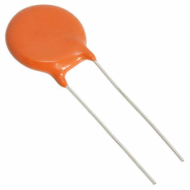
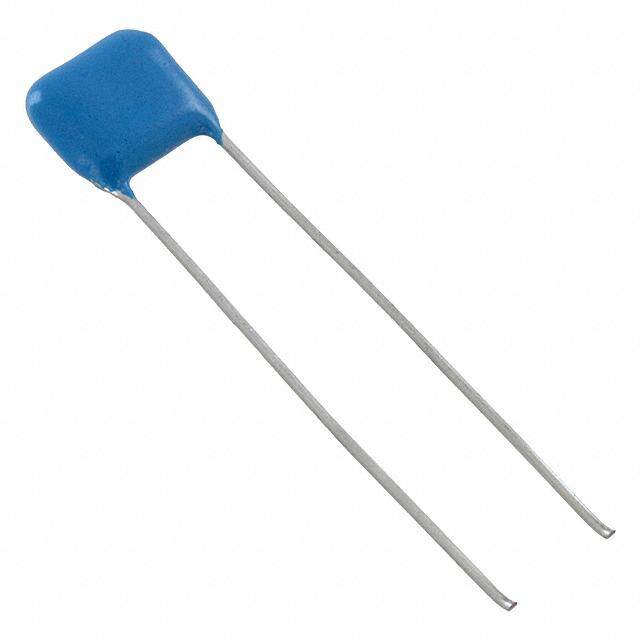
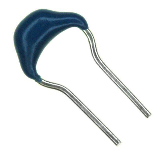
ICGOO电子元器件商城为您提供440LS10-R由Vishay设计生产,在icgoo商城现货销售,并且可以通过原厂、代理商等渠道进行代购。 440LS10-R价格参考。Vishay440LS10-R封装/规格:陶瓷电容器, 10000pF ±20% 760VAC 陶瓷电容器 Y5U(E) 径向,圆片式。您可以下载440LS10-R参考资料、Datasheet数据手册功能说明书,资料中有440LS10-R 详细功能的应用电路图电压和使用方法及教程。
Vishay Cera-Mite 440LS10-R 是一款陶瓷电容器,具有高可靠性和优异的电气性能。其应用场景广泛,尤其适用于需要高稳定性和耐高温特性的电路中。以下是该型号电容器的一些典型应用场景:

 1. 电源滤波与稳压
   在电源电路中,440LS10-R 可用于滤波和稳压。它能够有效抑制电源中的噪声和纹波,确保输出电压的稳定性。特别是在开关电源、线性电源等应用中,该电容器可以减少电磁干扰(EMI),提升系统的抗干扰能力。

 2. 高频电路
   由于其低ESR(等效串联电阻)和低ESL(等效串联电感),440LS10-R 非常适合用于高频电路。它可以有效地处理高频信号,如射频(RF)电路、通信设备中的滤波和耦合,确保信号的完整性。

 3. 脉冲电路
   在脉冲电路中,440LS10-R 能够快速响应瞬态电流变化,提供稳定的储能和放电功能。例如,在雷达系统、激光器驱动电路等需要快速充放电的应用中,该电容器表现出色。

 4. 汽车电子
   汽车电子系统对电容器的要求极为严格,尤其是在高温环境下。440LS10-R 具有良好的温度特性,能够在极端温度范围内保持稳定的性能,因此广泛应用于汽车点火系统、发动机控制单元(ECU)、车载娱乐系统等。

 5. 工业自动化
   在工业自动化领域,440LS10-R 可用于电机驱动器、变频器等设备中,帮助滤除噪声并稳定控制系统。其高可靠性确保了长时间运行下的稳定性,减少了维护成本。

 6. 航空航天
   航空航天领域对元器件的可靠性要求极高。440LS10-R 的高耐压、耐温特性使其成为卫星、飞机等高端设备的理想选择,能够在极端环境下长期稳定工作。

总之,Vishay Cera-Mite 440LS10-R 陶瓷电容器凭借其优异的电气性能和可靠性,广泛应用于电源管理、高频电路、脉冲电路、汽车电子、工业自动化以及航空航天等领域,为各种复杂环境下的电路提供了可靠的保障。
| 参数 | 数值 |
| 产品目录 | |
| 描述 | CAP CER 10000PF 400VAC RADIAL瓷片电容器 .01uF X7R 10% X1, 400Vac/Y1,500Vac |
| 产品分类 | |
| 品牌 | Vishay BC ComponentsVishay / Cera-Mite |
| 产品手册 | |
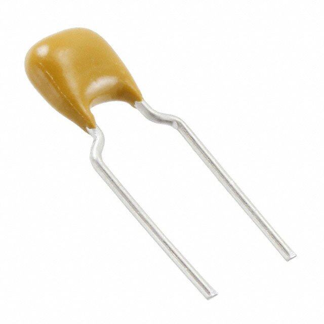
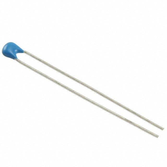
| 产品图片 |
|
| rohs | RoHS 合规性豁免无铅 / 符合限制有害物质指令(RoHS)规范要求 |
| 产品系列 | 陶瓷电容器,瓷片电容器,Vishay / Cera-Mite 440LS10-RCera-Mite 440L |
| 数据手册 | |
| 产品型号 | 440LS10-R440LS10-R |
| 产品 | Safety Ceramic Disc Capacitors |
| 产品种类 | 瓷片电容器 |
| 其它名称 | 440LS10R |
| 包装 | 散装 |
| 厚度(最大值) | - |
| 商标 | Vishay / Cera-Mite |
| 外壳直径 | 21.6 mm |
| 大小/尺寸 | 0.850" 直径(21.60mm) |
| 安装类型 | 通孔 |
| 容差 | ±20%20 % |
| 封装 | Bulk |
| 封装/外壳 | 径向,圆盘 |
| 工作温度 | -30°C ~ 125°C |
| 工作温度范围 | - 30 C to + 125 C |
| 工厂包装数量 | 100 |
| 应用 | 安全 |
| 引线形式 | - |
| 引线间距 | 0.374"(9.50mm) |
| 引线间隔 | 9.5 mm |
| 损耗因数DF | 2 |
| 最大工作温度 | + 125 C |
| 最小工作温度 | - 30 C |
| 标准包装 | 100 |
| 温度系数 | Y5U(E) |
| 温度系数/代码 | Y5U |
| 特性 | - |
| 电介质 | Y5U |
| 电压-额定 | 400VAC |
| 电压额定值 | 400 VAC |
| 电压额定值AC | 760 V, 500 V |
| 电容 | 0.01 uF10000pF |
| 端接类型 | Radial |
| 等级 | X1Y1 |
| 类 | X1, Y1 |
| 类型 | AC Line Rated Ceramic Disc Capacitors Class X1 760 VAC/Y1 500 VAC |
| 系列 | 440L |
| 高度-安装(最大值) | 0.976"(24.80mm) |


- 商务部:美国ITC正式对集成电路等产品启动337调查
- 曝三星4nm工艺存在良率问题 高通将骁龙8 Gen1或转产台积电
- 太阳诱电将投资9.5亿元在常州建新厂生产MLCC 预计2023年完工
- 英特尔发布欧洲新工厂建设计划 深化IDM 2.0 战略
- 台积电先进制程称霸业界 有大客户加持明年业绩稳了
- 达到5530亿美元!SIA预计今年全球半导体销售额将创下新高
- 英特尔拟将自动驾驶子公司Mobileye上市 估值或超500亿美元
- 三星加码芯片和SET,合并消费电子和移动部门,撤换高东真等 CEO
- 三星电子宣布重大人事变动 还合并消费电子和移动部门
- 海关总署:前11个月进口集成电路产品价值2.52万亿元 增长14.8%
PDF Datasheet 数据手册内容提取
440L Series www.vishay.com Vishay Cera-Mite AC Line Rated Ceramic Disc Capacitors Class X1, 760 V / Class Y1, 500 V AC AC FEATURES • Complies with IEC 60384-14 • High reliability • Radial leads • High capacitance up to 20 nF • Singlelayer AC disc safety capacitors • Material categorization: for definitions of complianc e please see www.vishay.com/doc?99912 APPLICATIONS • X1, Y1 according to IEC 60384-14 • Across-the-line ADDITIONAL RESOURCES • Line by-pass 3DDD 333D • Antenna coupling 3D Models Models DESIGN The capacitors consist of a ceramic disc of which both sides QUICK REFERENCE DATA are silver-plated. Connection leads are made of tinned DESCRIPTION VALUE copper having a diameter of 0.032" (0.81 mm). The Ceramic Class 1 2 capacitors may be supplied with radial kinked or straigh t C0G, C0G, leads having a lead spacing of 0.375" (9.5 mm). The U2J, U2J, X7R, X7R, standard tolerances are ± 10 % or ± 20 %. Coating is made Ceramic Dielectric P3K, P3K, Y5U Y5U of flame-retardant epoxy resin in accordance wit h R3L R3L “UL 94 V-0.” Voltage (V ) 500 760 500 760 AC Min. Capacitance (pF) 10 68 CAPACITANCE RANGE Max. Capacitance (pF) 47 20 000 10 pF to 20 nF Mounting Radial RATED VOLTAGE INSULATION RESISTANCE IEC 60384-14: Min. 1000 F • X1: 760 V , 50 Hz AC • Y1: 500 V , 50 Hz TOLERANCE ON CAPACITANCE AC ± 10 %; ± 20 % DIELECTRIC STRENGTH BETWEEN LEADS Component test: DISSIPATION FACTOR 4000 V , 50 Hz, 2 s AC 2.0 % max. at 1 kHz; 1 V As repeated test admissible only once with: 3600 V , 50 Hz, 2 s CERAMIC DIELECTRIC AC Random sampling test (destructive test): C0G, U2J, P3K, R3L (class 1) 4000 V , 50 Hz, 60 s AC X7R, Y5U (class 2) DIELECTRIC STRENGTH OF BODY OPERATING TEMPERATURE RANGE INSULATION -30 °C to +125 °C 4000 V , 50 Hz, 60 s (destructive test) AC CLIMATIC CATEGORY ACC. TO EN 60068-1 25/125/21 Revision: 17-Feb-2020 1 Document Number: 23102 For technical questions, contact: ceramitesupport@vishay.com THIS DOCUMENT IS SUBJECT TO CHANGE WITHOUT NOTICE. THE PRODUCTS DESCRIBED HEREIN AND THIS DOCUMENT ARE SUBJECT TO SPECIFIC DISCLAIMERS, SET FORTH AT www.vishay.com/doc?91000
440L Series www.vishay.com Vishay Cera-Mite DIMENSIONS in inches (millimeters) 440LS20-R T 1.25(302 m)in. LO 0.12(35. 2m)ax. max. Dmax. Tinned Copper Leads LS mDax. LS Ø 1.625 ± 0.125 Tmax. (41.3 ± 3.2) 0.125 max. (3.2) ORDERING INFORMATION, CERAMIC X1 / Y1 CAPACITORS 440L WIRE SIZE LS LO D T C TOL. max. max. LEAD SPACE LEAD OFFSET ORDERING DIAMETER THICKNESS (pF) (%) INCH (mm) INCH (mm) AWG INCH (mm) INCH (mm) INCH (mm) CODE ± 1 mm ± 0.5 mm C0G 10 ± 10 0.330 (8.4) 0.195 (5.0) 20 0.032 (0.81) 0.375 (9.5) 0.098 (2.5) 440LQ10-R U2J 15 ± 10 0.330 (8.4) 0.210 (5.3) 20 0.032 (0.81) 0.375 (9.5) 0.110 (2.8) 440LQ15-R P3K 22 ± 10 0.330 (8.4) 0.190 (4.8) 20 0.032 (0.81) 0.375 (9.5) 0.094 (2.4) 440LQ22-R R3L 33 ± 10 0.330 (8.4) 0.200 (5.1) 20 0.032 (0.81) 0.375 (9.5) 0.102 (2.6) 440LQ33-R 47 ± 10 0.330 (8.4) 0.180 (4.6) 20 0.032 (0.81) 0.375 (9.5) 0.083 (2.1) 440LQ47-R X7R 68 0.220 (5.6) 0.122 (3.1) 440LQ68-R 100 0.220 (5.6) 0.122 (3.1) 440LT10-R 150 ± 10 0.330 (8.4) 0.235 (6.0) 20 0.032 (0.81) 0.375 (9.5) 0.138 (3.5) 440LT15-R 220 0.235 (6.0) 0.138 (3.5) 440LT22-R 330 0.225 (5.7) 0.126 (3.2) 440LT33-R Y5U 470 0.330 (8.4) 0.230 (5.8) 0.130 (3.3) 440LT47-R 560 0.330 (8.4) 0.230 (5.8) 0.130 (3.3) 440LT56-R 680 0.330 (8.4) 0.235 (6.0) 0.138 (3.5) 440LT68-R 1000 0.365 (9.3) 0.225 (5.7) 0.126 (3.2) 440LD10-R 1500 0.365 (9.3) 0.220 (5.6) 0.118 (3.0) 440LD15-R 2000 0.400 (10.2) 0.220 (5.6) 0.118 (3.0) 440LD20-R 2200 0.430 (10.9) 0.225 (5.7) 0.126 (3.2) 440LD22-R 2700 0.460 (11.7) 0.225 (5.7) 0.126 (3.2) 440LD27-R 2800 0.460 (11.7) 0.220 (5.6) 0.122 (3.1) 440LD28-R 3000 0.490 (12.4) 0.225 (5.7) 0.126 (3.2) 440LD30-R 3200 0.490 (12.4) 0.220 (5.6) 0.122 (3.1) 440LD32-R 3300 ± 20 0.490 (12.4) 0.220 (5.6) 20 0.032 (0.81) 0.375 (9.5) 0.122 (3.1) 440LD33-R 3900 0.530 (13.5) 0.220 (5.6) 0.118 (3.0) 440LD39-R 4000 0.530 (13.5) 0.220 (5.6) 0.122 (3.1) 440LD40-R 4700 0.620 (15.7) 0.230 (5.8) 0.130 (3.3) 440LD47-R 5000 0.620 (15.7) 0.225 (5.7) 0.126 (3.2) 440LD50-R 5500 0.680 (17.3) 0.230 (5.8) 0.134 (3.4) 440LD55-R 5600 0.680 (17.3) 0.230 (5.8) 0.134 (3.4) 440LD56-R 6800 0.720 (18.3) 0.235 (6.0) 0.138 (3.5) 440LD68-R 8000 0.720 (18.3) 0.220 (5.6) 0.122 (3.1) 440LD80-R 9000 0.790 (20.1) 0.225 (5.7) 0.126 (3.2) 440LD90-R 10 000 0.850 (21.6) 0.230 (5.8) 0.134 (3.4) 440LS10-R 20 000 0.850 (21.6) 0.355 (9.0) 0.134 (3.4) 440LS20-R Notes • Alternate lead spacings are available bulk or tape and reel on request • Minimum lead clearance according to IEC 60384-14: 0.315" (8 mm) TAPE AND REEL OPTIONS Part number codes and specifications for tape and reel packaging are found in the general information document - find web-lin k below. Revision: 17-Feb-2020 2 Document Number: 23102 For technical questions, contact: ceramitesupport@vishay.com THIS DOCUMENT IS SUBJECT TO CHANGE WITHOUT NOTICE. THE PRODUCTS DESCRIBED HEREIN AND THIS DOCUMENT ARE SUBJECT TO SPECIFIC DISCLAIMERS, SET FORTH AT www.vishay.com/doc?91000
440L Series www.vishay.com Vishay Cera-Mite AC CURRENT VS. VOLTAGE (Leakage Current) Axis Title Axis Title 100 10000 1.0 10000 0.9 MS 80 440LQ47-R MS 0.8 R R 0.7 440LT68-R A) 1000 A) 1000 2nd lineCurrent (μ 4600 440LQ331st line-R2nd line 2nd lineCurrent (m 000...456 444400LLTT5467--1st lineRR2nd line Leakage 20 444144400000LLLQQQ211250---RRR Leakage 00..23 444144400000LLLTTT132532---RRR 0.1 440LT10-R 440LQ68-R 0 10 0 10 0 1000 2000 3000 4000 0 1000 2000 3000 4000 AC Voltage (V) RMS AC Voltage (V) RMS Axis Title Axis Title 3.0 10000 16 10000 50 Hz, 22 °C 440LS20-R 14 2.5 MS 444400LLDD3320--RR MS 12 R 440LD28-R R mA) 2.0 414000L0D27-R mA) 10 1000 2nd lineLeakage Current ( 011...505 444444414444444000000000LLLLLLLDTTTDDD65422118672050---1st line----RRRRRRR2nd line 2nd lineLeakage Current ( 468 444444144444400000000LLLLLLSDDDDD1865430086791st line------RRRRRR2nd line 2 0 10 0 10 0 500 1000150020002500300035004000 0 500 1000150020002500300035004000 AC Voltage (V) RMS AC Voltage (V) RMS IMPEDANCE VS. FREQUENCY (Wire Length 10 mm) Axis Title 1000 10000 100 10 1000 Ω) 2nd lineedance ( 1 440LQ10-R 1st line2nd line p Im 0.1 440LQ47-R 100 440LT47-R 0.01 440LD47-R 440LS20-R 0.001 10 0.1 1 10 100 1000 Frequency (MHz) Revision: 17-Feb-2020 3 Document Number: 23102 For technical questions, contact: ceramitesupport@vishay.com THIS DOCUMENT IS SUBJECT TO CHANGE WITHOUT NOTICE. THE PRODUCTS DESCRIBED HEREIN AND THIS DOCUMENT ARE SUBJECT TO SPECIFIC DISCLAIMERS, SET FORTH AT www.vishay.com/doc?91000
440L Series www.vishay.com Vishay Cera-Mite APPROVALS IEC 60384-14 - Safety tests This approval together with CB test certificate substitutes all national approvals. CB Certificate Y1-capacitor: CB test certificate: DE1-56450/A1 10 pF to 20 nF 500 V AC X1-capacitor: CB test certificate: DE1-56450/A1 10 pF to 20 nF 760 V AC VDE Y1-capacitor: VDE marks approval: 40003985 10 pF to 20 nF 500 V AC X1-capacitor: VDE marks approval: 40003985 10 pF to 20 nF 400 V AC DIN EN 60384-14 VDE 0565-1-1 - Safety tests Underwriters Laboratories Inc. Y1-capacitor: UL test certificate: E99264 10 pF to 20 nF 500 V AC X1-capacitor: UL test certificate: E99264 10 pF to 20 nF 760 V AC UL 60384-14, CSA E60384-1, CSA E60384-14 Fixed capacitors for electromagnetic interference suppression and connection to the supply mains. MARKING Sample CM 440L 102M IEC 60384-14 Y1 500V~ X1 760V~ XX - XXX Notes • Marking IEC 60384-14 does not apply for Ø 9 mm • Coding is as follows: 1st figure indicates the year and 2nd figure indicates the month according to IEC 60062. The 3rd to 5th figure indicate the last three digits of the lot number RELATED DOCUMENTS General Information www.vishay.com/doc?23140 CB Test Certificate www.vishay.com/doc?22237 VDE Marks Approval www.vishay.com/doc?22238 UL Test Certificate www.vishay.com/doc?22239 Revision: 17-Feb-2020 4 Document Number: 23102 For technical questions, contact: ceramitesupport@vishay.com THIS DOCUMENT IS SUBJECT TO CHANGE WITHOUT NOTICE. THE PRODUCTS DESCRIBED HEREIN AND THIS DOCUMENT ARE SUBJECT TO SPECIFIC DISCLAIMERS, SET FORTH AT www.vishay.com/doc?91000
Legal Disclaimer Notice www.vishay.com Vishay Disclaimer ALL PRODUCT, PRODUCT SPECIFICATIONS AND DATA ARE SUBJECT TO CHANGE WITHOUT NOTICE TO IMPROV E RELIABILITY, FUNCTION OR DESIGN OR OTHERWISE. Vishay Intertechnology, Inc., its affiliates, agents, and employees, and all persons acting on its or their behalf (collectively, “Vishay”), disclaim any and all liability for any errors, inaccuracies or incompleteness contained in any datasheet or in any other disclosure relating to any product. Vishay makes no warranty, representation or guarantee regarding the suitability of the products for any particular purpose o r the continuing production of any product. To the maximum extent permitted by applicable law, Vishay disclaims (i) any and all liability arising out of the application or use of any product, (ii) any and all liability, including without limitation special, consequential or incidental damages, and (iii) any and all implied warranties, including warranties of fitness for particular purpose, non-infringement and merchantability. Statements regarding the suitability of products for certain types of applications are based on Vishay’s knowledge of typical requirements that are often placed on Vishay products in generic applications. Such statements are not binding statements about the suitability of products for a particular application. It is the customer’s responsibility to validate that a particular product with the properties described in the product specification is suitable for use in a particular application. Parameters provided in datasheets and / or specifications may vary in different applications and performance may vary over time. All operating parameters, including typical parameters, must be validated for each customer application by the customer’s technical experts. Product specifications do not expand or otherwise modify Vishay’s terms and conditions of purchase, including but not limited to the warranty expressed therein. Except as expressly indicated in writing, Vishay products are not designed for use in medical, life-saving, or life-sustainin g applications or for any other application in which the failure of the Vishay product could result in personal injury or death. Customers using or selling Vishay products not expressly indicated for use in such applications do so at their own risk . Please contact authorized Vishay personnel to obtain written terms and conditions regarding products designed for such applications. No license, express or implied, by estoppel or otherwise, to any intellectual property rights is granted by this documen t or by any conduct of Vishay. Product names and markings noted herein may be trademarks of their respective owners. © 2019 VISHAY INTERTECHNOLOGY, INC. ALL RIGHTS RESERVED Revision: 01-Jan-2019 1 Document Number: 91000