ICGOO在线商城 > 传感器,变送器 > PMIC - 栅极驱动器 > AWM5104VN

 Datasheet下载
- 型号: AWM5104VN
- 制造商: Honeywell Solid State Electronics
- 库位|库存: xxxx|xxxx
- 要求:
| 数量阶梯 | 香港交货 | 国内含税 |
| +xxxx | $xxxx | ¥xxxx |
查看当月历史价格
查看今年历史价格
AWM5104VN产品简介:
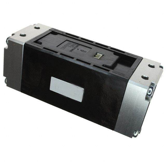
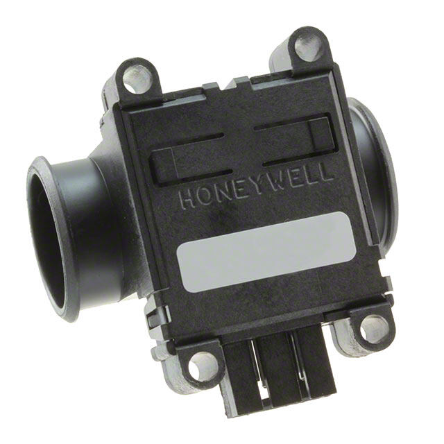
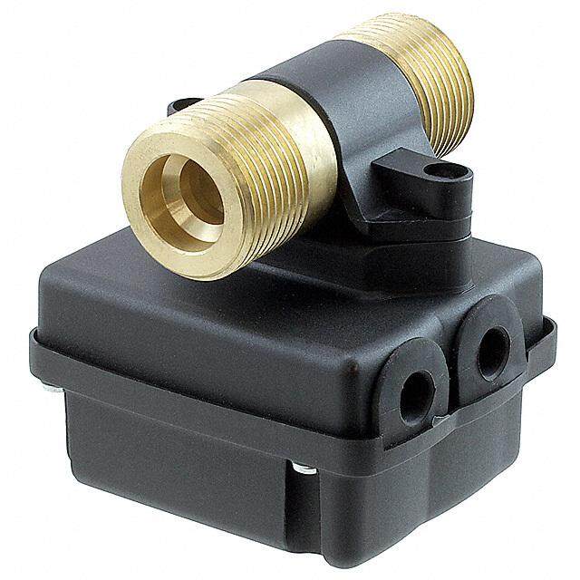
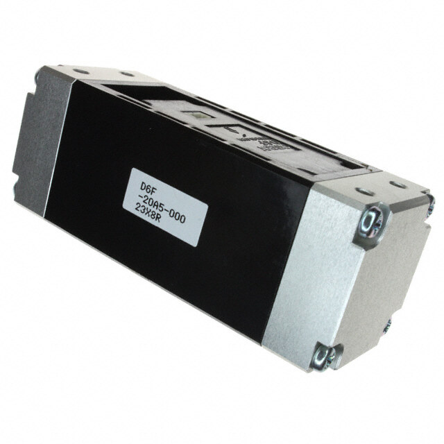
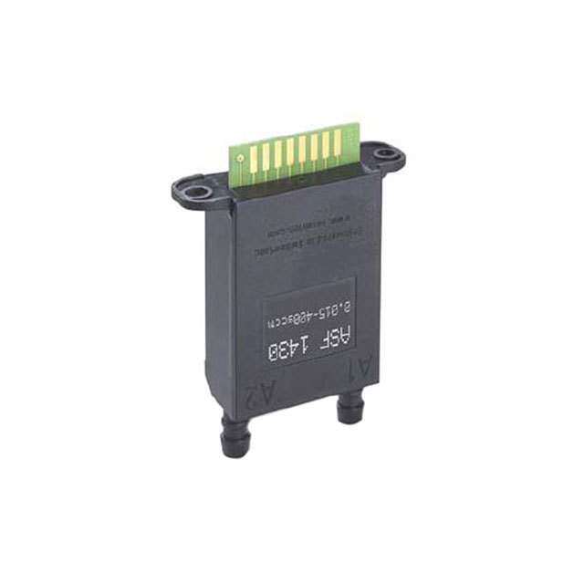
ICGOO电子元器件商城为您提供AWM5104VN由Honeywell Solid State Electronics设计生产,在icgoo商城现货销售,并且可以通过原厂、代理商等渠道进行代购。 AWM5104VN价格参考¥1027.99-¥1324.97。Honeywell Solid State ElectronicsAWM5104VN封装/规格:PMIC - 栅极驱动器, Air Flow Sensor 0 ~ 20 SLPM Male, 1/4", 0.25" (6.35mm) NPT Silicon。您可以下载AWM5104VN参考资料、Datasheet数据手册功能说明书,资料中有AWM5104VN 详细功能的应用电路图电压和使用方法及教程。
Honeywell Sensing and Productivity Solutions 的 AWM5104VN 是一款属于 PMIC(电源管理集成电路)- 栅极驱动器类别的产品。其主要应用场景包括但不限于以下领域:

 1. 工业自动化
   - 电机控制:AWM5104VN 可用于驱动工业电机的功率 MOSFET 或 IGBT,适用于变频器、伺服驱动器等设备。
   - 机器人系统:在工业机器人中,该器件可用于驱动关节控制器中的功率开关,实现高效的能量转换和精确的运动控制。

 2. 新能源领域
   - 太阳能逆变器:用于驱动逆变器中的功率开关器件,将直流电转换为交流电,提高能源利用效率。
   - 电动汽车(EV)充电设备:在 EV 充电站或车载充电器中,该栅极驱动器可帮助实现高效的电力转换和稳定的电流输出。

 3. 消费电子
   - 家电控制:如空调、冰箱、洗衣机等需要高效能电机驱动的家电,AWM5104VN 可用于优化电机性能,降低能耗。
   - 无人机:在无人机的动力系统中,该器件可以驱动无刷电机的功率开关,确保飞行稳定性和续航能力。

 4. 通信与网络设备
   - 基站电源:在通信基站中,AWM5104VN 可用于驱动功率开关,提供高效率的电源管理解决方案。
   - 服务器电源:在数据中心或高性能计算设备中,该器件可用于优化电源模块的性能,减少能量损耗。

 5. 医疗设备
   - 呼吸机和监护仪:在需要精密功率控制的医疗设备中,AWM5104VN 可用于驱动风扇、泵或其他关键组件,确保设备运行稳定可靠。

 特性优势
- 高可靠性:Honeywell 的产品以高可靠性著称,适用于恶劣环境下的应用。
- 低功耗设计:有助于延长电池寿命或降低系统整体能耗。
- 快速响应:支持高频开关操作,提升系统的动态性能。

综上所述,AWM5104VN 在需要高效功率转换和精准控制的应用场景中表现出色,广泛适用于工业、新能源、消费电子、通信及医疗等多个领域。
| 参数 | 数值 |
| 产品目录 | |
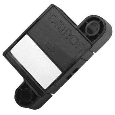
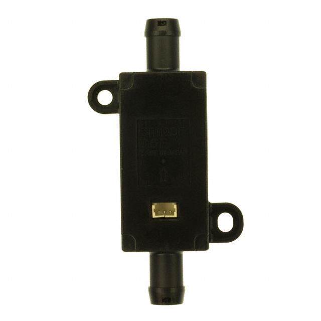
| 描述 | SENSOR AIRFLOW AMP 0-20 SLPM流量传感器 MASS AIRFLOW 20L/MIN Threaded 1/4 NPT |
| 产品分类 | 流量传感器流量传感器 |
| 品牌 | Honeywell |
| 产品手册 | http://sensing.honeywell.com/index.cfm?ci_id=140301&la_id=1&pr_id=106145 |
| 产品图片 |
|
| rohs | 符合RoHS无铅 / 符合限制有害物质指令(RoHS)规范要求 |
| 产品系列 | Honeywell AWM5104VNAWM5000 |
| 数据手册 | 点击此处下载产品Datasheethttp://sensing.honeywell.com/index.php/ci_id/54882/la_id/1/document/1/re_id/0http://sensing.honeywell.com/index.php/ci_id/50053/la_id/1/document/1/re_id/0 |
| 产品型号 | AWM5104VN |
| 产品目录绘图 |
|
| 产品目录页面 | |
| 产品种类 | 流量传感器 |
| 传感器类型 | Air Flow |
| 其它名称 | 480-2697 |
| 商标 | Honeywell |
| 工厂包装数量 | 5 |
| 开关功能/额定值 | - |
| 感应范围 | 0 ~ 20 SLPM |
| 材料-本体 | 硅 |
| 标准包装 | 5 |
| 模拟输出 | 5 V |
| 流量传感器类型 | 空气 |
| 特色产品 | http://www.digikey.com/cn/zh/ph/Honeywell/AWM.html |
| 电压-输入 | 8 V ~ 15 V |
| 电源电压 | 10 V |
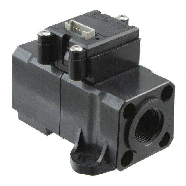
| 端口尺寸 | 公型,1/4",0.25"(6.35mm)NPT |
| 精度/可靠性 | +/- 0.5 % Reading |
| 额定范围 | 0 L/min to 20 L/min |


- 商务部:美国ITC正式对集成电路等产品启动337调查
- 曝三星4nm工艺存在良率问题 高通将骁龙8 Gen1或转产台积电
- 太阳诱电将投资9.5亿元在常州建新厂生产MLCC 预计2023年完工
- 英特尔发布欧洲新工厂建设计划 深化IDM 2.0 战略
- 台积电先进制程称霸业界 有大客户加持明年业绩稳了
- 达到5530亿美元!SIA预计今年全球半导体销售额将创下新高
- 英特尔拟将自动驾驶子公司Mobileye上市 估值或超500亿美元
- 三星加码芯片和SET,合并消费电子和移动部门,撤换高东真等 CEO
- 三星电子宣布重大人事变动 还合并消费电子和移动部门
- 海关总署:前11个月进口集成电路产品价值2.52万亿元 增长14.8%
PDF Datasheet 数据手册内容提取
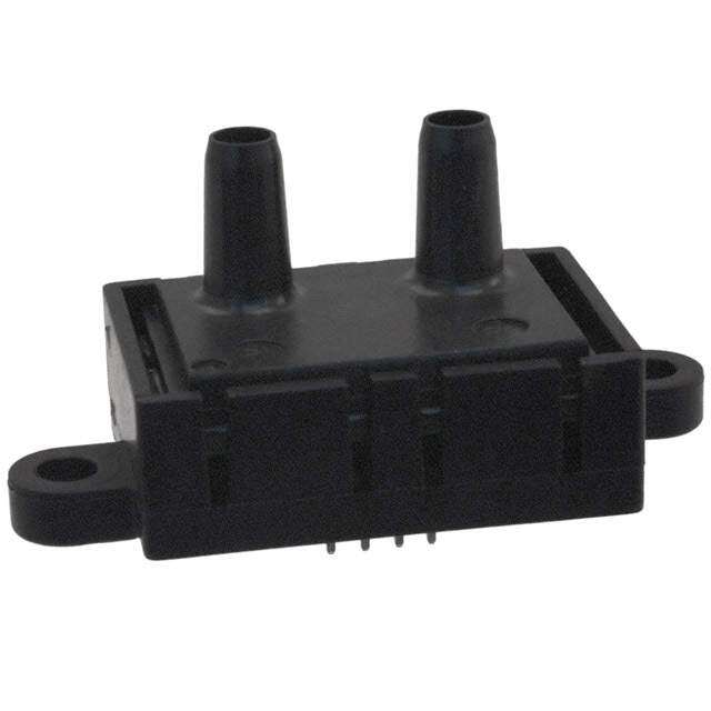
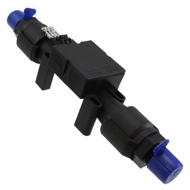
Airflow Sensors AWM5000 Series High Flow Mass Airflow/Amplified FEATURES (cid:49) Linear voltage output (cid:49) Venturi design (cid:49) Remote mounting capability (cid:49) Active laser trimming improves inter- change ability (cid:49) Separate gas calibration types: – Ar (argon) – N (nitrogen) or 2 – CO (carbon dioxide) 2 In-Line Flow Measurement AWM5000 Series Microbridge Mass Air- flow Sensors feature a venturi type flow housing. They measure flow as high as 20 Figure 1 standard liters per minute (SLPM) while inducing a maximum pressure drop of 2.25(cid:78)HO. The microbridge chip is in di- 2 rect contact with the flow stream, greatly reducing error possibilities due to orifice or bypass channel clogging. Rugged, Versatile Package The rugged plastic package has been designed to withstand common mode pressures up to 50 psi, and the small sensing element allows 100 gs of shock without compromising performance. The included ‘‘AMP’’ compatible connector provides reliable connection in demand- ing applications. On-board Signal Conditioning Each AWM5000 sensor contains circuitry Figure 2 which performs amplification, lineariza- tion, temperature compensation, and gas A calibration. Figure 1(Heater Control Cir- ir f cuit) and Figure 2 (Sensor Bridge Circuit lo and Amplification Linearization Circuit) il- w lustrate the on-board electrical circuitry for the AWM5000 Series. A 1 to 5 VDC linear output is possible for all listings regardless of flow range (5, 10, 15, or 20 SLPM) or calibration gas (nitrogen, car- bon dioxide, nitrous oxide, or argon). All calibration is performed by active laser trimming. Honeywell(cid:49) Sensing and Control(cid:49)1-800-537-6945 USA(cid:49)(cid:70)1-815-235-6847 International(cid:49)1-800-737-3360 Canada 79
Airflow Sensors AWM5000 Series Highflow Mass Airflow/Amplified SPECIFICATIONS (Performance Characteristics @10.0 ±0.01VDC, 25(cid:176) C) AWM5101 AWM5102 AWM5103 AWM5104 Flow Range (Note 3) 0-5 SLPM 0-10 SLPM 0-15 SLPM 0-20 SLPM Suffix - Calibration gas VA- Argon (Ar) VC- Carbon dioxide (CO) VN- Nitrogen (N) 2 2 Min. Typ. Max. Excitation VDC 8 10±0.01 15 Power consumption (mW) — — 100 Response time (msec) — — 60 Null output VDC 0.95 1 1.05 Null output shift −20(cid:176) to 70(cid:176) C — ±0.050 VDC ±.200 VDC Common Mode Pressure (psi) — — 50 Temperature range −20(cid:176) to +70(cid:176) C, (−4(cid:176) to 158(cid:176) F) Weight 60 grams (2.12 oz.) Shock ratings 100 g peak, 6 msec half-sine (3 drops, each direction of 3 axes) Output @ laser trim point 5 VDC @ Full Scale Flow Output voltage shift +20(cid:176) to −25(cid:176) C, +20(cid:176) to 70(cid:176) C Suffix VA or VN ±7.0% Reading, Suffix VC ±10.0% Reading Linearity error (2) ±3.0% Reading (max.) Repeatability & Hysteresis ±0.5% Reading (max.) Connector (Included) —Four pin receptacle MICRO SWITCH (SS12143)/AMP (103956-3) Leak rate, max 0.1 psi/min. at static condition, (Note 2) Notes: 1. Linearity specification applies from 2 to 100% full scale of gas flow range, and does not apply to null output at 0 SLPM. 2. The AWM5000 series product has a leakage spec of less than 0.1psi per minute at 50 psi common mode pressure. If during installation, the end adapters are twisted with respect to the flowtube, this may compromise the seal between the o-ring and the flowtube and may cause a temporary leak. This leak might be as high as 1psi or might remain in specification. It will self-reseal as the o-ring takes a new set. Approximately 85% of the leakage will dissipate in 24 hours. Within 48 hours, complete recovery will take place. 3. SLPM denotes standard liters per minute, which is a flow measurement referenced to standard conditions of 0(cid:176) C/1bar (sea level), 50% RH. NOTICE AWM5000—Chimney Effect AWM microbridge mass airflow sensors detect mass airflow caused by heat transfer. The thermally isolated microbridge structure consists of a heater resistor positioned between two temperature sensing resistors. The heater resistor maintains a constant temperature, 160(cid:176) C above ambient, during sensor operation. Airflow moving past the chip transfers heat from the heater resistor. This airflow warms the downstream resistor and cools the upstream resistor. The temperature change and the resulting change in resistance of the temperature resistors is proportional to the mass airflow across the sensing element. When the sensor is mounted in a vertical position, under zero flow conditions, the sensor may produce an output that is the result of thermally induced convection current. This occurrence is measurable in the AWM5000 Series, particularly in the 5 SLPM versions. When designing the sensor into applications where null stability is critical, avoid mounting the sensor in a vertical position. 80 Honeywell(cid:49) Sensing and Control(cid:49)1-800-537-6945 USA(cid:49)(cid:70)1-815-235-6847 International(cid:49)1-800-737-3360 Canada
Airflow Sensors AWM5000 Series High Flow Mass Airflow/Amplified OUTPUT CURVES (Performance Characteristics @10.0 ±0.01VDC, 25(cid:176) C) A ir f lo w Honeywell(cid:49)Sensing and Control(cid:49)1-800-537-6945 USA(cid:49)(cid:70)1-815-235-6847 International(cid:49)1-800-737-3360 Canada 81
Airflow Sensors AWM5000 Series Highflow Mass Airflow/Amplified AWM5000 ORDER GUIDE Catalog Listing Flow Range AWM5101VA 5 SLPM, Argon calibration AWM5101VC 5 SLPM, CO calibration (2) 2 AWM5101VN 5 SLPM, N calibration (1) 2 AWM5102VA 10 SLPM, Argon calibration AWM5102VC 10 SLPM, CO calibration (2) 2 AWM5102VN 10 SLPM, N calibration (1) 2 AWM5103VA 15 SLPM, Argon calibration AWM5103VC 15 SLPM, CO calibration (2) 2 AWM5103VN 15 SLPM, N calibration (1) 2 AWM5104VA 20 SLPM, Argon calibration AWM5104VC 20 SLPM, CO calibration (2) 2 AWM5104VN 20 SLPM, N calibration (1) 2 CONNECTOR ORDER GUIDE Catalog Listing Description SS12143 Four pin Electrical connector Connectors use Amp 103956-3 Note: All listings have 1- 5 VDC linear output with 10 VDC supply over given flow range for a specific calibration gas. 1.N calibration is identical to 0 and air calibration. 2 2 2.CO calibration is identical to NO calibration. 2 2 3.For additional gas correction factors, see Application Note 3. OUTPUT CONNECTIONS Pin 1 +Supply voltage Pin 2 Ground Pin 3 No connection Pin 4 Output voltage Arrow on bottom of housing indicates direction of flow. MOUNTING DIMENSIONS (for reference only) 82 Honeywell(cid:49) Sensing and Control(cid:49)1-800-537-6945 USA(cid:49)(cid:70)1-815-235-6847 International(cid:49)1-800-737-3360 Canada