ICGOO在线商城 > 传感器,变送器 > PMIC - 栅极驱动器 > AWM43600V

 Datasheet下载
- 型号: AWM43600V
- 制造商: Honeywell Solid State Electronics
- 库位|库存: xxxx|xxxx
- 要求:
| 数量阶梯 | 香港交货 | 国内含税 |
| +xxxx | $xxxx | ¥xxxx |
查看当月历史价格
查看今年历史价格
AWM43600V产品简介:
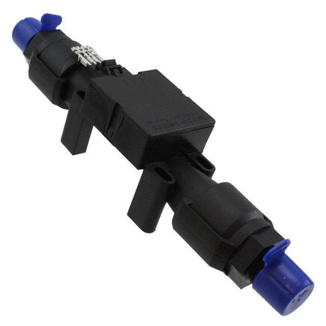
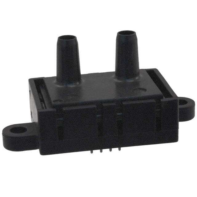
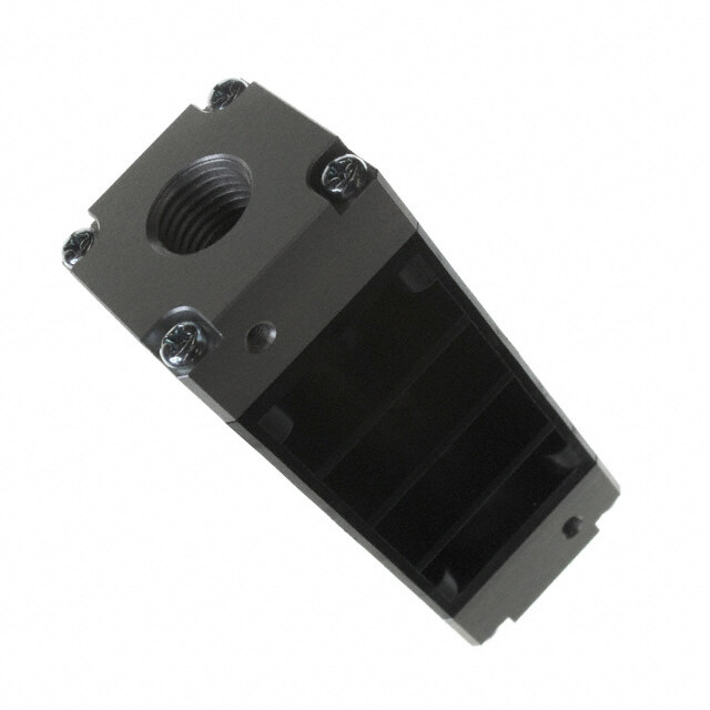
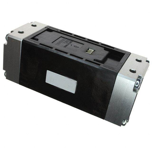
ICGOO电子元器件商城为您提供AWM43600V由Honeywell Solid State Electronics设计生产,在icgoo商城现货销售,并且可以通过原厂、代理商等渠道进行代购。 AWM43600V价格参考。Honeywell Solid State ElectronicsAWM43600V封装/规格:PMIC - 栅极驱动器, Air Flow Sensor 6 SLPM Female, 0.19" (4.826mm) Silicon。您可以下载AWM43600V参考资料、Datasheet数据手册功能说明书,资料中有AWM43600V 详细功能的应用电路图电压和使用方法及教程。
Honeywell Sensing and Productivity Solutions旗下的AWM43600V是一款属于PMIC(电源管理集成电路)中栅极驱动器类别的器件。该器件主要用于驱动功率MOSFET或IGBT等功率开关器件,在各类电力电子系统中发挥关键作用。

AWM43600V的应用场景主要包括:

1. 电机控制:用于工业自动化设备、伺服电机和步进电机的驱动控制,提供高效、可靠的栅极驱动能力。

2. 电源转换系统:如DC-DC转换器、AC-DC电源模块等,用于提升电源转换效率和稳定性。

3. 可再生能源系统:如太阳能逆变器、风能转换系统中,用于驱动功率开关,实现能量的高效转换与管理。

4. 电动汽车及充电设备:在车载充电器(OBC)、电机驱动系统中用于控制功率器件的导通与关断。

5. 工业自动化与机器人:在高精度运动控制系统中,实现快速响应与高效能管理。

AWM43600V具备高驱动能力、快速开关响应和良好的抗干扰性能,适合在高要求的工业与自动化环境中使用,有助于提升系统整体效率与可靠性。
| 参数 | 数值 |
| 产品目录 | |
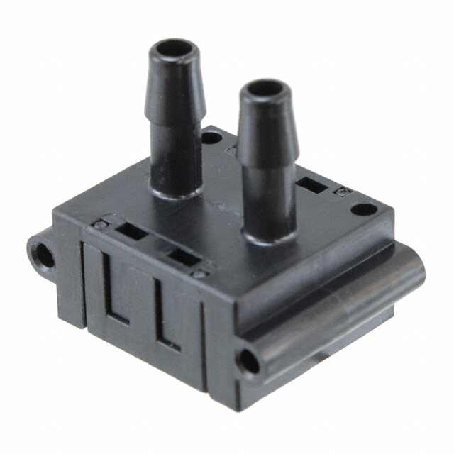
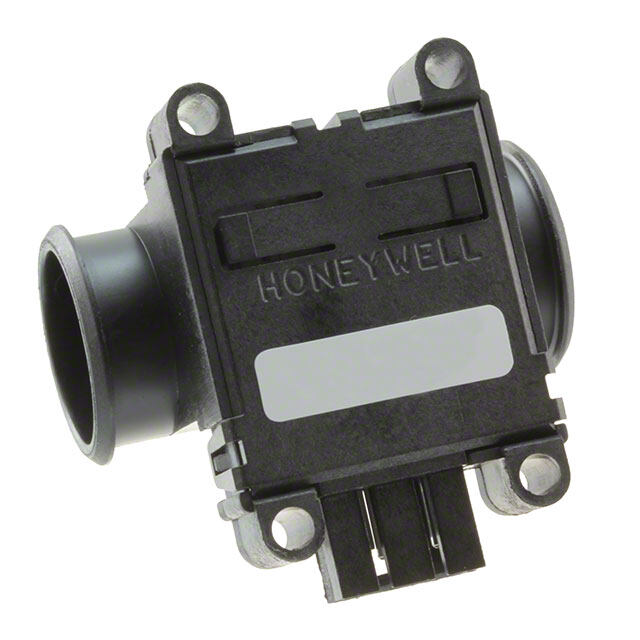
| 描述 | SENSOR AIRFLOW AMP 6 SLPM流量传感器 MASS AIRFLOW Manifold |
| 产品分类 | 流量传感器流量传感器 |
| 品牌 | Honeywell |
| 产品手册 | http://sensing.honeywell.com/index.cfm?ci_id=140301&la_id=1&pr_id=106067 |
| 产品图片 |
|
| rohs | 符合RoHS无铅 / 符合限制有害物质指令(RoHS)规范要求 |
| 产品系列 | Honeywell AWM43600VAWM40000 |
| 数据手册 | 点击此处下载产品Datasheethttp://sensing.honeywell.com/index.php/ci_id/54882/la_id/1/document/1/re_id/0http://sensing.honeywell.com/index.php/ci_id/50054/la_id/1/document/1/re_id/0 |
| 产品型号 | AWM43600V |
| 产品目录绘图 |
|
| 产品目录页面 | |
| 产品种类 | 流量传感器 |
| 传感器类型 | Air Flow |
| 其它名称 | 480-2695-5 |
| 商标 | Honeywell |
| 工厂包装数量 | 10 |
| 开关功能/额定值 | - |
| 感应范围 | 6 SLPM |
| 材料-本体 | 硅 |
| 标准包装 | 10 |
| 模拟输出 | 5 V |
| 流量传感器类型 | 空气 |
| 电压-输入 | 8 V ~ 15 V |
| 电源电压 | 10 V |
| 端口尺寸 | 母型,0.19"(4.826mm) |
| 精度/可靠性 | +/- 1 % Reading |
| 额定范围 | 6 L/min |


- 商务部:美国ITC正式对集成电路等产品启动337调查
- 曝三星4nm工艺存在良率问题 高通将骁龙8 Gen1或转产台积电
- 太阳诱电将投资9.5亿元在常州建新厂生产MLCC 预计2023年完工
- 英特尔发布欧洲新工厂建设计划 深化IDM 2.0 战略
- 台积电先进制程称霸业界 有大客户加持明年业绩稳了
- 达到5530亿美元!SIA预计今年全球半导体销售额将创下新高
- 英特尔拟将自动驾驶子公司Mobileye上市 估值或超500亿美元
- 三星加码芯片和SET,合并消费电子和移动部门,撤换高东真等 CEO
- 三星电子宣布重大人事变动 还合并消费电子和移动部门
- 海关总署:前11个月进口集成电路产品价值2.52万亿元 增长14.8%

PDF Datasheet 数据手册内容提取
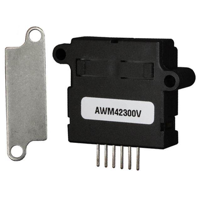
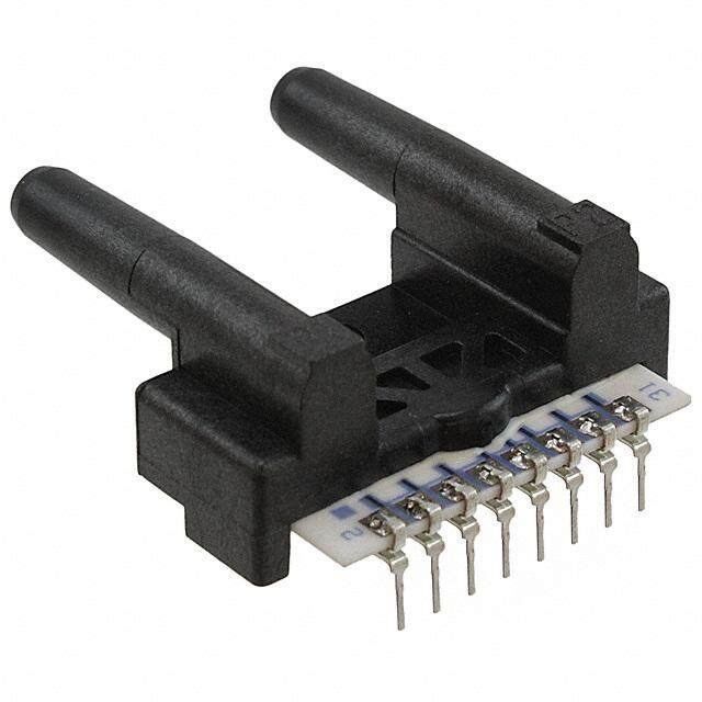
Airflow Sensors AWM40000 Series Microbridge Mass Airflow/Unamplified and Amplified Figure 1 Heater Control Circuit FEATURES (cid:49) Manifold mount/o-ring sealed (cid:49) Ceramic flow-tube (non-outgassing), 0-1000 sccm (cid:49) Plastic flow tube, 0-6 SLPM (cid:49) High common mode pressure (150 psi ceramic flow-tube only) (cid:49) Operating temperature up to 125(cid:176) C Figure 2 (unamplified only) Sensing Bridge Supply Circuit (cid:49) High stability at null and full-scale The AWM40000 Series mass flow sensor family is based on proven microbridge technology and includes both amplified signal conditioned devices and unampli- fied sensor only devices. When using the unamplified devices (AWM42150VH and AWM42300V), the heater control circuit in Figure 1and the sensing bridge supply circuit in Figure 2 Figure 3 are both required for operation per speci- Differential Instrumentation Amplifier Circuit fication. These two circuits are NOT on board the sensor and must be supplied in the application. The differential amplifier circuitry in Figure 3 may be useful in pro- viding output gain and/or introducing voltage offsets to the sensor output (Ref. Equation 1). The amplified devices (AWM43300V and AWM43600V) can be used to increase output gain and introduce voltage offsets. The differential instrumentation amplifier circuitry, heater control circuitry and sensing bridge supply circuitry are all provided onboard the amplified sensors. Equation 1: ( )( )( ) 2R+R R V(cid:74) 2 1 4 V-V +V offset o R R 2 1 1 3 ( ) R 6 where V offset(cid:74)V S R R 6+ 5 76 Honeywell(cid:49)Sensing and Control(cid:49)1-800-537-6945 USA(cid:49)(cid:70)1-815-235-6847 International(cid:49)1-800-737-3360 Canada
Airflow Sensors AWM40000 Series Microbridge Mass Airflow/Unamplified and Amplified AWM40000 SERIES ORDER GUIDE (Performance Characteristics @10.01±0.01VDC, 25(cid:176) C) Catalog Listings AWM42150VH AWM42300V AWM43300V AWM43600V Flow Range (Full Scale) ±25 sccm ±1000 sccm +1000 sccm +6 SLPM Output Voltage @ Trim Point 8.5 mV ±1.5 mV 54.7 mV ±3.7 mV DC 5 V ±0.15 VDC 5 V ±0.15 VDC @ 6 SLPM @ 25 sccm @ 1000 sccm @ 1000 sccm Null Voltage 0.0 ±1.0 mVDC 0.0 ±1.5 mVDC 1.0 ±0.05 VDC 1.0 ±0.05 VDC Null Voltage Shift +25(cid:176) to −25(cid:176) C, +25(cid:176) to +85(cid:176) C ±0.20 mVDC ±0.20 mVDC ±0.025 VDC ±0.025 VDC Output Voltage Shift +25(cid:176) to −25(cid:176) C +2.5% Reading typ. +2.5% Reading max. −5.0% Reading max. −6.0% Reading max. +25(cid:176) to +85(cid:176) C −2.5% Reading typ. −2.5% Reading max. +6.0% Reading max. +6.0% Reading max. Power Consumption (mW) 60 (Max.) 60 (Max.) 60 (Max.) 75 (Max.) Repeatability & Hysteresis ±0.35% Reading (3) ±0.50% Reading ±0.50% Reading ±1.00% Reading Pressure Drop @ Full Scale (in HO) 0.008(cid:78)HO (Typ.) 1.02 (Typ.) 1.02 (Typ.) 8.00 (Typ.) 2 2 Min. Typ. Max. Excitation VDC 8.0 10±0.01 15 Response Time (msec) — 1.0 3.0 (Note 1) Common Mode Pressure (psi) (max.) — — 150 psi (10 Bar) 25 psi (1.7 Bar) Output Load NPN (Sinking): 10 mA PNP (Sourcing): 20 mA Temperature Range Operating: −40(cid:176) to +125(cid:176) C (−40(cid:176) to +251(cid:176) F) Operating: −25(cid:176) to +85(cid:176) C (−13(cid:176) to +185(cid:176) F) Storage: −40(cid:176) to +125(cid:176) C (−40(cid:176) to +251(cid:176) F) Storage: −40(cid:176) to +90(cid:176) C (−40(cid:176) to +194(cid:176) F) Calibration Gas Nitrogen Ratiometricity Error ±0.30% Reading Weight (grams) 14 g 11 g Shock Rating 100 g peak (5 drops, 6 axes) Termination 2,54 mm (.100(cid:78)) centers, 0,635 cm (0.025(cid:78)) square Notes: A 1. Response time is typically 1msec from 10 to 90%. ir 2. Repeatability & Hysteresis tolerances reflect inherent inaccuracies of the measurement equipment. flo 3. Maximum allowable rate of flow change to prevent damage: 5.0 SLPM/1.0 sec. w MOUNTING DIMENSIONS (for reference only) Amplified Sensors Unamplified Sensors Note: Positive flow direction is defined as proceeding from Port 1(P1) to Port 2 (P2), and results in positive output. Honeywell(cid:49) Sensing and Control(cid:49)1-800-537-6945 USA(cid:49)(cid:70)1-815-235-6847 International(cid:49)1-800-737-3360 Canada 77
Airflow Sensors AWM40000 Series Microbridge Mass Airflow/Unamplified and Amplified OUTPUT FLOW VS INTERCHANGEABILITY (Note 1) Performance Characteristics @ 10.0 ±0.01VDC, 25(cid:176) C AWM42150VH AWM42300V AWM43300V AWM43600V Press Flow Nom. Tol. Press. Flow Nom. Tol. Press. Flow Nom. Tol. Press. Flow Nom. Tol. (cid:109)Bar sccm mV ±mV mBar sccm mV ±mV mBar sccm VDC ±VDC mBar SLPM VDC ±VDC 20 30 9.9 1.5 2.23 1000 54.7 2.00 2.23 1000 5.00 0.15 20.0 6 5.00 0.15 17 25 8.5 1.5 1.52 800 53.0 2.0 1.87 900 4.97 0.16 14.7 5 4.89 0.20 14 20 6.8 1.5 0.94 600 49.3 2.5 1.52 800 4.89 0.17 9.07 4 4.70 0.25 10 15 5.2 1.0 0.49 400 42.5 3.5 1.16 700 4.78 0.18 6.40 3 4.40 0.35 7 10 3.5 1.0 0.19 200 29.8 4.0 0.94 600 4.63 0.19 3.35 2 3.80 0.30 3 5 1.7 1.0 0.00 0 0.0 1.5 0.71 500 4.43 0.20 1.17 1 3.10 0.30 0 0 0.0 1.0 -0.19 -200 -29.8 4.0 0.50 400 4.15 0.21 0.00 0 1.00 0.05 -0.49 -400 -42.5 5.0 0.33 300 3.76 0.19 -0.94 -600 -49.3 6.0 0.19 200 3.23 0.17 -1.52 -800 -53.0 6.0 0.08 100 2.49 0.14 -2.23 -1000 -55.2 6.0 0.00 0 1.00 0.05 Notes: 1. Numbers in BOLD type indicate calibration type, mass flow or differential pressure. Tolerance values apply to calibration type only. 78 Honeywell(cid:49) Sensing and Control(cid:49)1-800-537-6945 USA(cid:49)(cid:70)1-815-235-6847 International(cid:49)1-800-737-3360 Canada