ICGOO在线商城 > 传感器,变送器 > PMIC - 栅极驱动器 > HAFBLF0200CAAX3
 Datasheet下载
- 型号: HAFBLF0200CAAX3
- 制造商: Honeywell Solid State Electronics
- 库位|库存: xxxx|xxxx
- 要求:
| 数量阶梯 | 香港交货 | 国内含税 |
| +xxxx | $xxxx | ¥xxxx |
查看当月历史价格
查看今年历史价格
HAFBLF0200CAAX3产品简介:
ICGOO电子元器件商城为您提供HAFBLF0200CAAX3由Honeywell Solid State Electronics设计生产,在icgoo商城现货销售,并且可以通过原厂、代理商等渠道进行代购。 HAFBLF0200CAAX3价格参考¥919.57-¥919.57。Honeywell Solid State ElectronicsHAFBLF0200CAAX3封装/规格:PMIC - 栅极驱动器, Air Flow Sensor 200sccm Male, 0.210" (5.35mm) Tube, Dual Polymer。您可以下载HAFBLF0200CAAX3参考资料、Datasheet数据手册功能说明书,资料中有HAFBLF0200CAAX3 详细功能的应用电路图电压和使用方法及教程。
Honeywell Sensing and Productivity Solutions 旗下的 HAFBLF0200CAAX3 是一款属于 PMIC(电源管理集成电路)类别中的栅极驱动器,主要用于高效驱动功率半导体器件(如MOSFET、IGBT等)。该器件广泛应用于需要高效率、高可靠性和紧凑设计的电力电子系统中。

典型应用场景包括:工业电机驱动、可再生能源系统(如太阳能逆变器和风能转换系统)、电动汽车(EV)及混合动力汽车(HEV)的车载充电器与牵引逆变器、不间断电源(UPS)以及开关电源(SMPS)。其高集成度和优化的驱动能力有助于提升系统能效,降低功耗和发热。

HAFBLF0200CAAX3 具备快速开关响应、高噪声抗扰性以及集成保护功能(如欠压锁定和过温保护),适用于高温、高电磁干扰的严苛工业环境。此外,该器件支持高频工作,有助于减小外围元件尺寸,实现更紧凑的电源设计。

综上,HAFBLF0200CAAX3 特别适合对可靠性、能效和空间布局要求较高的中高功率电力控制应用,是现代智能化工业与绿色能源系统中的关键驱动组件。
| 参数 | 数值 |
| 产品目录 | |
| 描述 | SENSOR AIRFLOW 200SCCM LONG 3.3V流量传感器 Long Port 3VDC +/-2.5% 200SCCM |
| 产品分类 | 流量传感器流量传感器 |
| 品牌 | Honeywell |
| 产品手册 | |
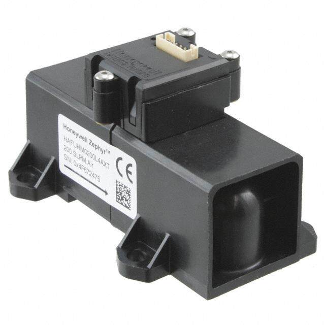
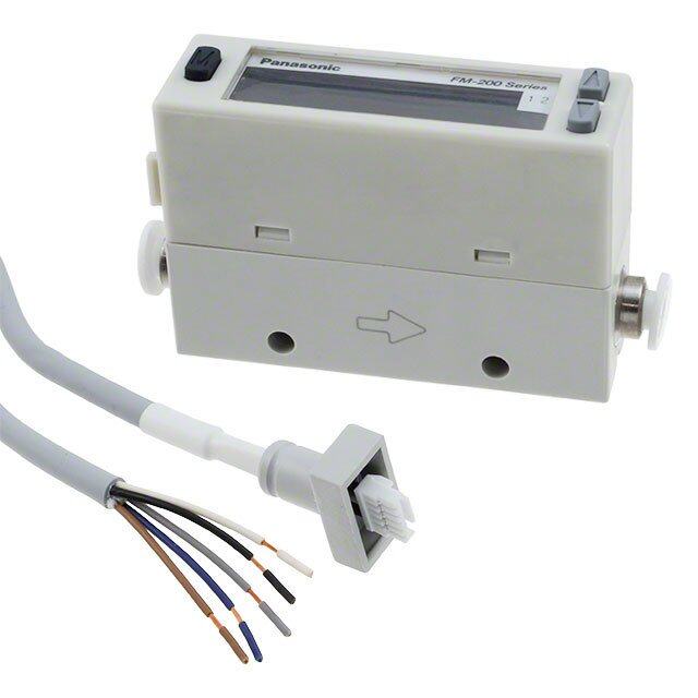
| 产品图片 |
|
| rohs | 符合RoHS无铅 / 符合限制有害物质指令(RoHS)规范要求 |
| 产品系列 | Honeywell HAFBLF0200CAAX3Zephyr™ HAF |
| 数据手册 | http://sensing.honeywell.com/index.php/ci_id/44423/la_id/1/document/1/re_id/0http://sensing.honeywell.com/index.php?ci_id=144883点击此处下载产品Datasheet |
| 产品型号 | HAFBLF0200CAAX3 |
| 产品培训模块 | http://www.digikey.cn/PTM/IndividualPTM.page?site=cn&lang=zhs&ptm=25023http://www.digikey.cn/PTM/IndividualPTM.page?site=cn&lang=zhs&ptm=25863 |
| 产品种类 | 流量传感器 |
| 传感器类型 | Air Flow |
| 其它名称 | 480-3323 |
| 商标 | Honeywell |
| 商标名 | Zephyr |
| 工厂包装数量 | 30 |
| 开关功能/额定值 | - |
| 感应范围 | 200 sccm |
| 材料-本体 | 聚合物 |
| 标准包装 | 30 |
| 流量传感器类型 | 空气 |
| 电压-输入 | 2.97 V ~ 3.63 V |
| 电源电压 | 3.3 V |
| 端口大小 | Long Port |
| 端口尺寸 | 公型,0.210"(5.35mm)双管 |
| 类型 | High Accuracy Air Flow Sensor |
| 精度/可靠性 | 2.5 % |
| 系列 | HAF |
| 额定范围 | 200 SCCM |


- 商务部:美国ITC正式对集成电路等产品启动337调查
- 曝三星4nm工艺存在良率问题 高通将骁龙8 Gen1或转产台积电
- 太阳诱电将投资9.5亿元在常州建新厂生产MLCC 预计2023年完工
- 英特尔发布欧洲新工厂建设计划 深化IDM 2.0 战略
- 台积电先进制程称霸业界 有大客户加持明年业绩稳了
- 达到5530亿美元!SIA预计今年全球半导体销售额将创下新高
- 英特尔拟将自动驾驶子公司Mobileye上市 估值或超500亿美元
- 三星加码芯片和SET,合并消费电子和移动部门,撤换高东真等 CEO
- 三星电子宣布重大人事变动 还合并消费电子和移动部门
- 海关总署:前11个月进口集成电路产品价值2.52万亿元 增长14.8%

PDF Datasheet 数据手册内容提取
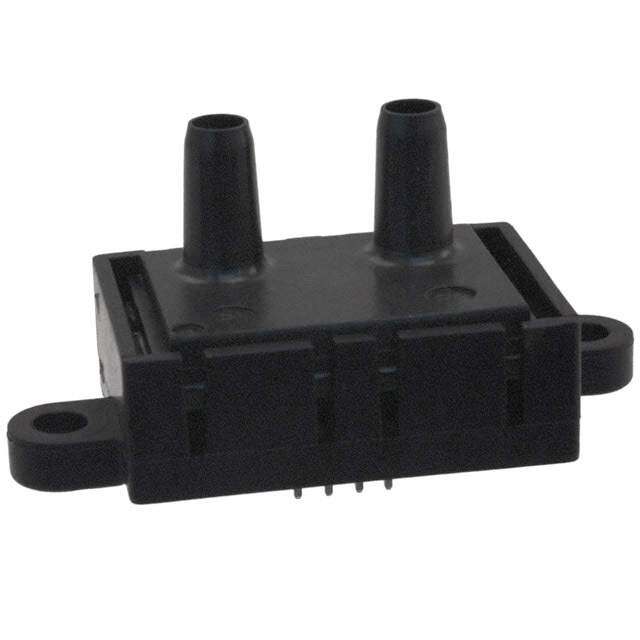
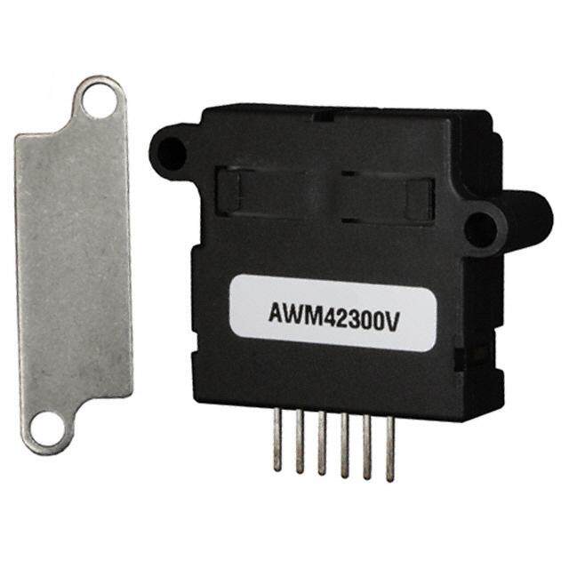
Honeywell ZephyrTM Digital Airflow Sensors HAF Series–High Accuracy ±50 SCCM to ±750 SCCM Datasheet
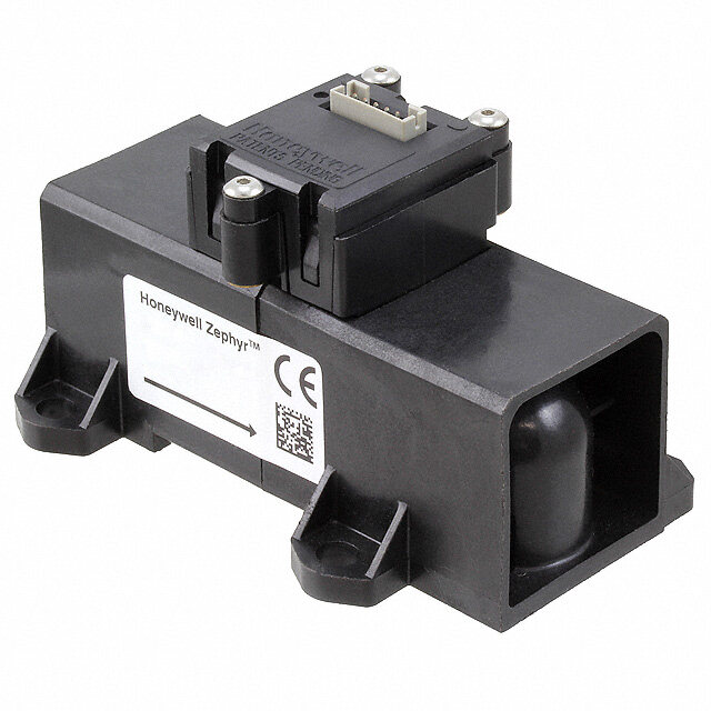
Honeywell ZephyrTM Digital Airflow Sensors HAF Series - High Accuracy Honeywell Zephyr™ HAF Series sensors provide a digital interface for reading airflow over specified full-scale flow and compensated temperature ranges. The thermally isolated heater and temperature sensing elements help these sensors provide a fast response to air or gas flow. Zephyr sensors are designed to measure mass flow of air and other non-corrosive gases. Standard flow ranges are available at ±50, ±100, ±200, ±400 or ±750 SCCM. Custom flow ranges are also available. The sensors are fully calibrated and temperature compensated with an onboard Application Specific Integrated Circuit (ASIC). The HAF Series is compensated over the temperature range of 0 °C to 50 °C [32 °F to 122 °F] and operates across a temperature range of -20 °C to 70 °C [-4 °F to 158 °F]. The state-of-the-art ASIC-based compensation provides digital (I2C) outputs with a response time of 1 ms. These sensors operate on the heat transfer principle to measure mass airflow. They consist of a microbridge Microelectronic and Microelectromechanical System (MEMS) with temperature-sensitive resistors deposited with thin films of platinum and silicon nitride. The MEMS sensing die is located in a precise and carefully-designed airflow channel to provide repeatable response to flow. Zephyr sensors provide the customer with enhanced reliability, high accuracy, repeatable measurements and the ability to customize sensor options to meet many specific application needs. The combination of rugged housings with a stable substrate makes these products extremely robust. They are designed and manufactured according to ISO 9001 standards. What makes our sensors better? Fast response time Wide range of airflows Customizable flow ranges and configurable package styles Linear output High stability Low pressure drop TIGHT TOTAL ERROR BAND • fAsT REspONsE TIME • WIDE RANGE Of AIRfLOWs 2 sensing.honeywell.com
Features and Benefits ToTAL Error BAnd (TEB) AS LoW AS 0.25%FSS* Allows for precise airflow measurement, often ideal for demanding applications with high accuracy requirements. All Possible Errors Offset + Full Scale Span + Linearity = Accuracy + Flow Hysteresis Total + = Error Band Repeatability + Temperature Offset + Temperature Span + Thermal Hysteresis Figure 1. Total Error Band vs. Accuracy Other airflow sensor manufacturers only report on accuracy, while Honeywell reports Total Error Band. FAST rESPonSE TIME* Allows a customer’s application to respond quickly to airflow change, important in critical medical (e.g., anesthesia) and industrial (e.g., fume hood) applications. WIdE rAngE oF AIrFLoWS* Zephyr measures mass flow at standard flow ranges of ±50, ±100 ±200, ±400 or ±750 SCCM, or custom flow ranges, increasing the options for integrating the sensor into the application. CuSToMIzABLE FLoW rAngES And ConFIgurABLE PACkAgE STyLES* Meet specific end-user needs. FuLL CALIBrATIon And TEMPErATurE CoMPEnSATIon Typically allow customer to remove additional components associated with signal conditioning from the PCB, reducing PCB size as well as costs often associated with those components (e.g., acquisition, inventory, assembly). *Competitive Differentiator sensing.honeywell.com 3
Features LInEAr ouTPuT* Provides more intuitive sensor signal than the raw output of basic airflow sensors, and Benefits which can help reduce production costs, design, and implementation time. LoW PrESSurE droP* Typically improves patient comfort in medical applications, and reduces noise and system wear on other components such as motors and pumps. HIgH 12-BIT rESoLuTIon Increases ability to sense small airflow changes, allowing customers to more precisely control their application. LoW 3.3 VdC oPErATIng VoLTAgE oPTIon And LoW PoWEr ConSuMPTIon Allow for use in battery-driven and other portable applications. ASIC-BASEd I2C dIgITAL ouTPuT CoMPATIBILITy Eases integration to microprocessors or microcontrollers, reducing PCB complexity and component count. InSEnSITIVITy To ALTITudE Eliminates customer-implemented altitude adjustments in the system, easing integration and reducing production costs by not having to purchase additional sensors for altitude adjustments. SMALL SIzE Occupies less space on PCB, allowing easier fit and potentially reducing production costs; PCB size may also be reduced for easier fit into space-constrained applications. roHS-CoMPLIAnT MATErIALS Meet Directive 2002/95/EC. *Competitive Differentiator 4 sensing.honeywell.com
Potential Applications MEdICAL AnESTHESIA dELIVEry MACHInES VEnTrICuLAr ASSIST dEVICES (HEArT PuMPS) nEBuLIzErS oxygEn ConCEnTrATorS PATIEnT MonITorIng SySTEMS (rESPIrATory MonITorIng) SLEEP APnEA MACHInES SPIroMETErS VEnTILATorS LAPAroSCoPy InduSTrIAL AIr-To-FuEL rATIo FuEL CELLS gAS LEAk dETECTIon VAV SySTEM on HVAC SySTEMS gAS METErS HVAC FILTErS sensing.honeywell.com 5
Honeywell ZephyrTM Digital Airflow Sensors HAF Series–High Accuracy Table 1. Absolute Maximum ratings1 Characteristic Parameter Supply voltage -0.3 Vdc to 6.0 Vdc Voltage on I/O output pin -0.3 Vdc to Vsupply Storage temperature range -40 °C to 125 °C [-40 °F to 257 °F] Maximum flow change 5.0 SLPM/s Maximum common mode pressure 25 psi at 25 °C [77 °F] Maximum flow 10 SLPM 1Absolute maximum ratings are the extreme limits that the device will withstand without damage to the device. However, the electrical and mechanical characteristics are not guaranteed as the maximum limits (above recommended operating conditions) are approached, nor will the device necessarily operate at absolute maximum ratings. CAUTION CAUTION IMPROPER USE PRODUCT DAMAGE Do not use these products to sense liquid flow. Do not disassemble these products. Failure to comply with these instructions may result in Failure to comply with these instructions may result in product damage. product damage. Table 2. operating Specifications Characteristic Parameter notes Supply voltage 3.3 Vdc 3.3 Vdc ±10% — 5.0 Vdc 5.0 Vdc ±10% Power: 3.3 Vdc 40 mW max. 1 5.0 Vdc 65 mW max. Compensated temperature range 0 °C to 50 °C [32 °F to 122 °F] 2 Operating temperature range -20 °C to 70 °C [-4 °F to 158 °F] — Accuracy See Table 3. 3, 4 Total Error Band (TEB) See Table 3. 4, 5 Null accuracy 0.1 %FSS 4, 6 Response time 1 ms typ. 7 Resolution 12 bit min. — Start-up time 17 ms 8 Warm-up time 30 ms 9 Calibration media gaseous nitrogen 10 Bus standards I2C fast mode (up to 400 kHz) 11 Null stability Null will not deviate beyond the specified TEB. — Reverse polarity protection no — 1Maximum Power: Is measured under the conditions of the highest supply voltage Vsupply + 10%, 70° C, full scale flow and with the minimum pull-up resistors for SDA and SCL according to the I2C specification. 2Custom and extended compensated temperature ranges are possible. Contact Honeywell for details. 3Accuracy: The maximum deviation from the nominal digital output over the compensated flow range at a reference temperature of 25 °C. Errors include offset, span, non-linearity, hysteresis and non-repeatability. 4Full Scale Span (FSS): The algebraic difference between the digital output at the forward Full Scale (FS) flow and the digital output at the reverse FS flow. Forward flow is defined as flow from P1 to P2 as shown in Figure 4. The references to mass flow (SCCM) refer to gas flows at the standard conditions of 0 °C and atmospheric pressure 760 (101.3 kPa). 5Total Error Band (TEB): The maximum deviation in output from ideal transfer function over the entire compensated temperature and flow range. Includes all errors due to offset, full scale span, flow hysteresis, flow repeatability, thermal effect on offset, thermal effect on span and thermal hysteresis. 6Null accuracy: The the maximum deviation in output at 0 SCCM from the ideal transfer function over the compensated temperature range. This includes offset errors, thermal airflow hysteresis and repeatability errors. 7Response time: The time to electrically respond to any mass flow change at the microbridge airflow transducer (response time of the transducer may be affected by the pneumatic interface). 8Start-up time: The time to first valid reading of serial number proceeding streaming 14-bit flow measurements. 9Warm-up time: The time to the first valid flow measurement after power is applied. 10Default calibration media is dry nitrogen gas. Please contact Honeywell for other calibration options. 11Refer to the Technical Note “I2C Communications with Honeywell Digital Airflow Sensors” for I2C protocol information. 6 sensing.honeywell.com
±50 SCCM to ±750 SCCM Table 3. Bidirectional Forward Flow optimization Accuracy Error Band Total Error Band Error (%FSS) Error (%FSS) See table below for null accuracy. See table below for null accuracy. Sensor range Airflow (SCCM) Airflow (SCCM) (SCCM) Applied Flow Accuracy Error TEB Applied Flow (SCCM) (SCCM) (%FSS) (%FSS) -50 to -16.7 ±6% reading -50 to -14.3 ±7% reading -16.7 to 0 ±1 -14.3 to 0 ±1 ±50 00 ±0.16 00 ±0.16 0 to 20 ±1 0 to 14.3 ±1 20 to 50 ±5% reading -14.3 to 50 ±7% reading -100 to -14.3 ±7% reading -100 to -14.3 ±7% reading -14.3 to 0 ±0.5 -14.3 to 0 ±0.5 ±100 00 ±0.12 00 ±0.12 20 ±0.5 0 to 16.7 ±0.5 20 to 100 ±5% reading 16.7 to 100 ±6% reading -200 to -11.1 ±9% reading -200 to -11.1 ±9% reading) -11.1 to -0 ±0.25 -11.1 to -0 ±0.25 ±2001 00 ±0.01 00 ±0.1 0 to 40 ±0.25 0 to 22.2 ±0.25 40 to 200 ±2.5% reading 22.2 to 200 ±4.5% reading -400 to -26.7 ±9% reading -400 to -32 10% reading -26.7 to -0 ±0.3 -32 to -0 ±0.4 ±400 00 ±0.1 00 ±0.1 0 to 68.6 ±0.3 0 to 71.1 ±0.4 68.6 to 400 ±3.5% reading 71.1 to 400 ±4.5% reading -750 to -31.3 ±12% reading -750 to -31.25 ±12% reading -31.3 to -0 ±0.25 -31.25 to -0 ±0.25 ±750 00 ±0.1 00 ±0.1 0 to 68.2 ±0.25 0 to 50 ±0.25 68.2 to 750 ±5.5% reading 50 to 750 ±7.5 reading 1The short port sensors are only specified down to -100 SCCM. sensing.honeywell.com 7
Honeywell ZephyrTM Digital Airflow Sensors HAF Series–High Accuracy CAUTION LARGE PARTICULATE DAMAGE Use a 5-micron filter upstream of the sensor to keep media flow through the sensor free of condensing moisture and particulates. Large, high-velocity particles or conductive particles may damage the sensing element. Failure to comply with these instructions may result in product damage. Table 4. Environmental Characteristics Table 5. Wetted Materials Characteristic Parameter Characteristic Parameter Humidity 0% to 95% RH, non-condensing Covers high temperature polymer Shock 100 g, 11 ms Substrate PCB Vibration 15 g at 20 Hz to 2000 Hz Adhesives epoxy Electronic silicon, gold components ESD Class 3B per MIL-STD 883G Compliance RoHS, WEEE Table 6. recommended Mounting and Implementation Characteristic Parameter Mounting screw: size 5-40 torque 0,68 N m [6 in-lb] Silicon tubing for long port style 70 durometer; size 0.125 in inside diameter, 0.250 in outside diameter silicone tubing O-ring: for short port style AS568A, Size 7, Silicone, Shore A 70 for long port style AS568A, Size 10, Silicone, Shore A 70 Filter 5-micron filter upstream of the sensor Figure 2. nominal digital output 18000 ) s 16000 t n u 14000 o 12000 C ( 10000 t u p 8000 t u O 6000 l 4000 a t gi 2000 i D 0 -2000 -150.00% -100.00% -50.00% 0.00% 50.00% 100.00% 150.00% Flow (%FS) 8 sensing.honeywell.com
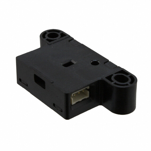
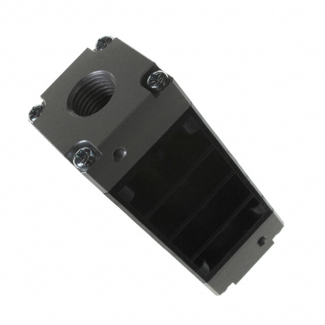
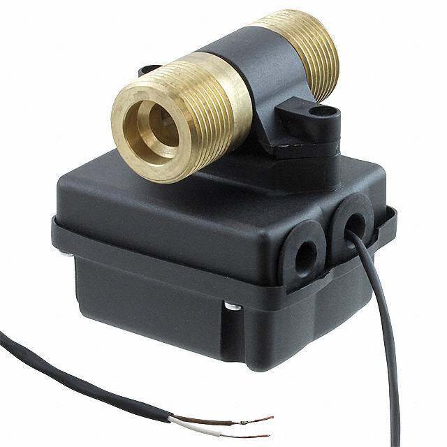
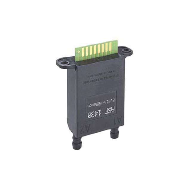
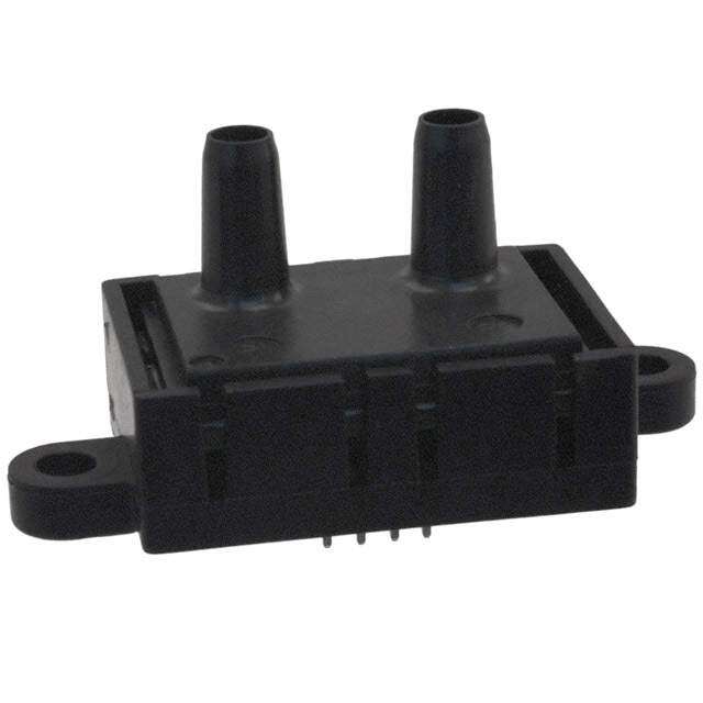
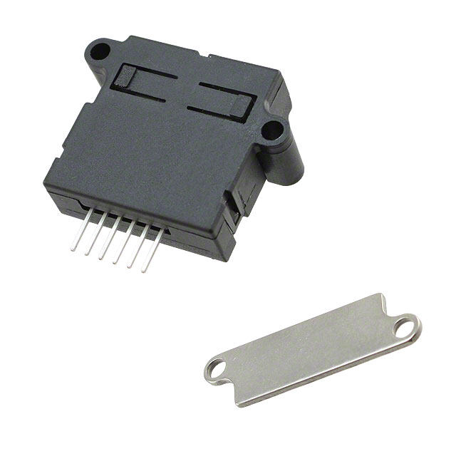
±50 SCCM to ±750 SCCM Figure 3. ideal Transfer Function Digital Output Code = 16384 * [0.5 + 0.4 * (Flow Applied/Full Scale Flow)] Flow Applied = Full Scale Flow * [(Digital Output Code/16384) - 0.5]/0.4 Figure 4. nomenclature and order guide For example, a HAFBLF0200C4AX5 part number defines a Honeywell ZephyrTM Digital Airflow Sensor, bidirectional forward flow optimized, long port, fastener mount, 200 SCCM, I2C output with address 0x49, 10% to 90% transfer function, 5.0 Vdc supply voltage. HAF B L F 0200 C 4 A X 5 Flow Transfer Reserved for Supply Product Series Direction Port Style Housing Style Flow Range2 Unit Output Format Function Future Use Voltage HiHghA FA cSceurrieascy B Bfoirdwiraercdt ioflonwal L Long port1 F Fmaosutennter 0050 5st0y lleo nogn lpyort CSCCM 4 D0xig4i9tal I2C address: A 1F0u%ll S tcoa 9le0 %Ou otpfut X XXXXX 3 3.3 Vdc Airflow Sensor optimized S Short port S Snap 0100 100 long port 5 Digital I2C address: (FSO) 5 5.0 Vdc mount1 style only 0x59 S Bidirectional symmetric 0200 200 long or 6 Digital I2C address: short port 0x69 0400 400 long port 7 Digital I2C address: style only 0x79 750 long port 0750 style only 1The Long Port Port Style with the Snap Mount Housing Style is not a valid configuration. 2The 200 SCCM Flow Range is available in the Long and Short Port Styles. Apart from the general configuration required, other customer-specific requirements are also possible. Please contact Honeywell. Figure 5. All Available Standard Configurations LF: Long port, fastener mount SF: Short port, fastener mount SS: Short port, snap mount sensing.honeywell.com 9
Honeywell ZephyrTM Digital Airflow Sensors HAF Series–High Accuracy Figure 6. Wave Solder Profile 300 Max. temp. = 243 °C ) 250 C Max. temp. = 205 °C ° ( 200 re Housing temp. (top of device) u 150 t Pin temp. (bottom of device) a er 100 p m 50 e T 0 0 20 40 60 80 100 Time (s) Figure 7. Long Port Style Flow vs Pressure Flow Typical Pressure drop (SCCM) mbar inHo Pa 2 -750 -0.2517 -0.1011 -25.17 -550 -0.1499 -0.0602 -14.99 -400 -0.0891 -0.0358 -8.91 0.12 O) -300 -0.0578 -0.0232 -5.78 H2 n0.06 -200 -0.0321 -0.0129 -3.21 (i N p -100 -0.0114 -0.0046 -1.14 o Dr 0 -50 -0.0035 -0.0014 -0.35 e r -20 -0.0007 -0.0003 -0.07 u s-0.06 s 0 0.0000 0.0000 0.0000 e r P 20 0.0007 0.0003 0.07 -0.12 -750 -600 -450 -300 -150 0 150 300 450 600 750 50 0.0035 0.0014 0.35 Flow (SCCM) 100 0.0014 0.0046 0.14 200 0.0321 0.0129 3.21 300 0.0578 0.0232 5.78 400 0.0891 0.0358 8.91 550 0.1499 0.0602 14.99 750 0.2517 0.1011 25.17 Figure 8. Short Port Style Flow vs Pressure Flow Typical Pressure drop 0.6 O) (SCCM) mbar inH2o Pa H2 0.4 -200 -1.1707 -0.470 -117.07 n p (i 0.2 -150 -0.7074 -0.284 -70.74 o -100 -0.3562 -0.143 -35.62 Dr 0 e -50 -0.1120 -0.045 -11.20 ur -0.2 s 0 0.0000 0.000 0.0000 s e N Pr -0.4 50 0.1196 0.048 11.96 -0.6 100 0.3462 0.139 34.62 -200 -150 -100 -50 0 50 100 150 200 150 0.7149 0.287 71.49 Flow (SCCM) 200 1.2589 0.452 125.89 10 sensing.honeywell.com
±50 SCCM to ±750 SCCM Dlgital Interface For additional details on the use of Zephyr with digital output see the Technical Note “I2C Communications with Honeywell Digital Airflow Sensors”. The sensor uses the I2C standard for digital communication with a slave address specified in the Nomenclature and Order Guide in Figure 4. Following sensor power-up, each of the first two read sequences shown in Figure 9 will respond with 2 bytes of the unique 4-byte Serial Number. The first read after power-up will respond with the two most significant bytes of the Serial Number, while the second read will respond with the two least significant bytes of the Serial Number. For reliable performance, allow sensor to be powered for the sensor start-up time before performing the first read, then allow a 10 ms command response time before performing the second read. Figure 9. Sensor I2C read and Write Sequences I2C Read: Slave responds to Master with data Data Byte 0 (Most Significant) Data Byte 1 (Least Significant) SDA S A6 A5 A4 A3 A2 A1 A0 1 SA D7 D6 D5 D4 D3 D2 D1 D0 MA D7 D6 D5 D4 D3 D2 D1 D0 MN S SCL I2C Read: Master sends data to Slave Command Byte SDA S A6 A5 A4 A3 A2 A1 A0 1 SA D7 D6 D5 D4 D3 D2 D1 D0 MA S SCL Bit Name Description S Start condition Master pulls SDA from high to low while SCL remains high S Stop condition Master allows SDA to float from low to high while SCL remains high A6 Address bit I2C Slave Address is the 7 Most Significant Bits for the first transmitted byte 1 Read/write bit Read = 1, Write = 0 D7 Data bit SA Slave ACK Slave pulls SDA low MA Master ACK Master pulls SDA low MN Master NACK Master allows SDA to float high After the power-up read sequence described above, the sensor will respond to each I2C read request with a 16-bit (2 byte) digital flow reading. Read requests taken faster than the Response Time (1 ms) are not guaranteed to return fresh data. The first two bits of each flow reading will be ‘00’. The maximum sink current on SCL or SDA is 2 mA. Therefore, if the pull-up resistors are biased by V , and if V reaches the maximum supply DD DD voltage of 6 V, then the pull-up resistors for SCL and SDA must be greater than 3.0 kΩ to limit the sink current to 2 mA. The typical value for SCL and SDA pull-up resistors is 4.7 kΩ (this value depends on the bus capacitance and the bus speed). sensing.honeywell.com 11
Honeywell ZephyrTM Digital Airflow Sensors HAF Series–High Accuracy Figure 10. Mounting dimensions (For reference only: mm [in].) LF: Long port, fastener mount MODEL NUMBER LOT CODE Honeywell Zephyr™ HAFBLFXXXXXXXXX 0x123456789 Mounting Footprint (cid:55)(cid:40)(cid:53)(cid:48)(cid:44)(cid:49)(cid:36)(cid:47)(cid:3)(cid:54)(cid:44)(cid:39)(cid:40) [03.,102] [ 02.,00709 T]YP. [10,.0004] 3,50 [70,.2208] 36,00 (cid:20)(cid:21) (cid:22) (cid:23) [0.14] 18,00 [1.42] [0.71] 10,3 [0.40] (cid:20) (cid:21) (cid:22) (cid:23) 7,20 [0.28] 10,00 [0.39] 4X DIA. 0,812 [0.032] 2X DIA. 5,35 [0.21] 2X DIA. 3,40 (cid:21)(cid:59)(cid:3)(cid:51)(cid:50)(cid:53)(cid:55)(cid:54) [0.134] 6,50 (cid:54)(cid:40)(cid:49)(cid:54)(cid:50)(cid:53)(cid:3)(cid:41)(cid:50)(cid:50)(cid:55)(cid:51)(cid:53)(cid:44)(cid:49)(cid:55) [0.26] (cid:57)(cid:44)(cid:40)(cid:58)(cid:40)(cid:39)(cid:3)(cid:41)(cid:53)(cid:50)(cid:48)(cid:3)(cid:55)(cid:40)(cid:53)(cid:48)(cid:44)(cid:49)(cid:36)(cid:47)(cid:3)(cid:54)(cid:44)(cid:39)(cid:40) 7,20 19,90 [0.28] [0.78] 2X DIA. 3,40 [0.13] 6,35 [0.25] 12,70 [0.50] 28,80 36,00 [1.13] [1.42] AIRFLOW DIRECTION, PORT SIDE SF: Short port, fastener mount MODEL NUMBER LOT CODE Honeywell Zephyr™ HAFBSFXXXXXXXXX 0x123456789 (cid:55)(cid:40)(cid:53)(cid:48)(cid:44)(cid:49)(cid:36)(cid:47)(cid:3)(cid:54)(cid:44)(cid:39)(cid:40) Mounting Footprint [03.,102] [ 02.,00709 T]YP.1 2 3 4 [10,.0004] [30,.5104] [70,.2208] 18,00 3[16.,4020] [0.71] 10,3 [0.40] (cid:20) (cid:21) (cid:22) (cid:23) 7,20 [0.28] 2X DIA. 4,00 2,50 [0.16] 4X DIA. 0,812 [0.10] [0.032] 6,50 2X DIA. 3,40 [0.26] (cid:21)(cid:59)(cid:3)(cid:51)(cid:50)(cid:53)(cid:55)(cid:54) (cid:54)(cid:40)(cid:49)(cid:54)(cid:50)(cid:53)(cid:3)(cid:41)(cid:50)(cid:50)(cid:55)(cid:51)(cid:53)(cid:44)(cid:49)(cid:55) [0.134] (cid:57)(cid:44)(cid:40)(cid:58)(cid:40)(cid:39)(cid:3)(cid:41)(cid:53)(cid:50)(cid:48)(cid:3)(cid:55)(cid:40)(cid:53)(cid:48)(cid:44)(cid:49)(cid:36)(cid:47)(cid:3)(cid:54)(cid:44)(cid:39)(cid:40) 7,20 19,90 [0.28] [0.78] 2X DIA. 3,40 [0.13] 6,35 [0.25] 12,70 [0.50] 28,80 36,00 [1.13] [1.42] AIRFLOW DIRECTION, PORT SIDE 12 sensing.honeywell.com
±50 SCCM to ±750 SCCM Figure 10. Mounting dimensions (For reference only: mm [in], continued.) SS: Short port, snap mount 22,00 [0.87] DIA. 2,30 MODEL NUMBER [0.09] LOT CODE Honeywell Zephyr™ HAFBSSXXXXXXXXX 0x123456789 Mounting Footprint (cid:55)(cid:40)(cid:53)(cid:48)(cid:44)(cid:49)(cid:36)(cid:47)(cid:3)(cid:54)(cid:44)(cid:39)(cid:40) 6,50 10,40 [0.26] [0.41] 26,00 7,20 2X DIA. 2,2 [0.086] THRU [03.,133] [ 02.,00709 T]YP. [ 1.02][10.,0040] [0.28] [40,.6108] 4 X D I A .[ 00.,083122] [02.826,06] H O L E S FO[R03 .M,185O00U]NTING 4,80 3,00 0,65 (cid:20) (cid:21) (cid:22) (cid:23) [0.19] [0.12] [0.026] [01.,08701]10,3 12,8 (cid:20) (cid:21) (cid:22) (cid:23) [04.1,0507] 2 X [ 07.,2280] [0.40] [0.50] 2X 2,50 [0.098] 2,50 [0.10] (cid:21)(cid:59)(cid:3)(cid:51)(cid:50)(cid:53)(cid:55)(cid:54) 26,00 [1.024] (cid:54)(cid:40)(cid:49)(cid:54)(cid:50)(cid:53)(cid:3)(cid:41)(cid:50)(cid:50)(cid:55)(cid:51)(cid:53)(cid:44)(cid:49)(cid:55) (cid:57)(cid:44)(cid:40)(cid:58)(cid:40)(cid:39)(cid:3)(cid:41)(cid:53)(cid:50)(cid:48)(cid:3)(cid:55)(cid:40)(cid:53)(cid:48)(cid:44)(cid:49)(cid:36)(cid:47)(cid:3)(cid:54)(cid:44)(cid:39)(cid:40) 19,90 [0.78] 6,35 [0.25] 12,70 [0.50] 28,80 [1.13] AIRFLOW DIRECTION, PORT SIDE 10 Table 8. Pinout Pin 1 Pin 2 Pin 3 Pin 4 SCL Vsupply ground SDA sensing.honeywell.com 13
AddITIonAL InForMATIon WArnIng The following associated literature is available at sensing. PErSonAL InJury honeywell.com: DO NOT USE these products as safety or emergency stop • Product line guide devices or in any other application where failure of the product • Product part listing/nomenclature tree could result in personal injury. • Product range guide Failure to comply with these instructions could result in • Technical Information: death or serious injury. – I2C Communications with Honeywell Digital Airflow Sensors WArnIng – Gas Media Compatibility and Correction Factors MISuSE oF doCuMEnTATIon • Installation instructions • The information presented in this product sheet is for • Application-specific information reference only. Do not use this document as a product installation guide. • Complete installation, operation, and maintenance information is provided in the instructions supplied with each product. Failure to comply with these instructions could result in death or serious injury. WArrAnTy/rEMEdy Honeywell warrants goods of its manufacture as being free of defective materials and faulty workmanship. Honeywell’s standard product warranty applies unless agreed to otherwise by Honeywell in writing; please refer to your order acknowledgement or consult your local sales office for specific warranty details. If warranted goods are returned to Honeywell during the period of coverage, Honeywell will repair or replace, at its option, without charge those items it finds defective. The foregoing is buyer’s sole remedy and is in lieu of all other warranties, expressed or implied, including those of merchantability and fitness for Find out more a particular purpose. In no event shall Honeywell be liable Honeywell serves its customers for consequential, special, or indirect damages. through a worldwide network of sales offices, representatives While we provide application assistance personally, through our and distributors. For application literature and the Honeywell website, it is up to the customer to assistance, current specifications, determine the suitability of the product in the application. pricing or name of the nearest Authorized Distributor, contact Specifications may change without notice. The information we your local sales office. supply is believed to be accurate and reliable as of this printing. To learn more about Honeywell’s However, we assume no responsibility for its use. sensing and control products, call +1-815-235-6847 or 1-800-537-6945, visit sensing.honeywell.com, or e-mail inquiries to info.sc@honeywell.com Sensing and Control Honeywell 1985 Douglas Drive North Golden Valley, MN 55422 32308684-A-EN June 2015 honeywell.com 2015 Honeywell International Inc. All rights reserved.
Mouser Electronics Authorized Distributor Click to View Pricing, Inventory, Delivery & Lifecycle Information: H oneywell: HAFBLF0200C2AX5 HAFBSS0200C2AX3 HAFBLF0200C2AX3 HAFBSF0200C2AX3 HAFBSF0200C2AX5 HAFBSS0200C2AX5 HAFBLF0050C4AX5 HAFBLF0750C4AX5 HAFBLF0050CAAX5 HAFBLF0750CAAX5 HAFBSF0200CAAX5 HAFBLF0200CAAX3 HAFBSS0200CAAX5 HAFBSF0200CAAX3 HAFBLF0200CAAX5 HAFBSS0200CAAX3 HAFBLF0200C4AX3 HAFBLF0200C4AX5 HAFBSF0200C4AX3 HAFBSF0200C4AX5 HAFBSS0200C4AX3 HAFBSS0200C4AX5 HAFBLF0100CAAX3 HAFBLF0750C4AX3 HAFBLF0100C4AX5 HAFBLF0100C4AX3 HAFBLF0750CAAX3 HAFBLF0100CAAX5 HAFBLF0400CAAX3 HAFBLF0400C4AX5 HAFBLF0400CAAX5 HAFBLF0050CAAX3 HAFBLF0050C4AX3 HAFBLF0400C4AX3 HAFBLF0200C5AX5 HAFBLF0200C6AX5 HAFBLF0200C7AX5 HAFBLF0050C5AX5 HAFBLF0050C6AX5 HAFBLF0050C7AX5 HAFBSF0200C5AX5 HAFBSF0200C6AX5 HAFBSF0200C7AX5 HAFSLF0750C4AX5 HAFBSF0400CAAX5 HAFSLF0050CAAX3 HAFSLF0100CAAX3 HAFSLF0100CAAX5 HAFSLF0200CAAX3 HAFSLF0200CAAX5 HAFSLF0400CAAX3 HAFSLF0400CAAX5 HAFSLF0750CAAX3 HAFSLF0750CAAX5 HAFBLF0050C2AX5 HAFBLF0400C5AX3 HAFBSS0200C5AX3 HAFBLF0200C5AX3 HAFSLF0050C4AX3 HAFSLF0050C4AX5 HAFSLF0050CAAX5 HAFSLF0100C4AX3 HAFSLF0100C4AX5 HAFSLF0200C4AX3 HAFSLF0200C4AX5 HAFSLF0400C4AX3 HAFSLF0400C4AX5 HAFSLF0750C4AX3