ICGOO在线商城 > 5916G6

 Datasheet下载
- 型号: 5916G6
- 制造商: ANDERSON POWER PRODUCTS
- 库位|库存: xxxx|xxxx
- 要求:
| 数量阶梯 | 香港交货 | 国内含税 |
| +xxxx | $xxxx | ¥xxxx |
查看当月历史价格
查看今年历史价格
5916G6产品简介:
ICGOO电子元器件商城为您提供5916G6由ANDERSON POWER PRODUCTS设计生产,在icgoo商城现货销售,并且可以通过原厂、代理商等渠道进行代购。 提供5916G6价格参考¥13.24-¥27.11以及ANDERSON POWER PRODUCTS5916G6封装/规格参数等产品信息。 你可以下载5916G6参考资料、Datasheet数据手册功能说明书, 资料中有5916G6详细功能的应用电路图电压和使用方法及教程。
| 参数 | 数值 |
| 品牌 | Anderson Power Products |
| 产品目录 | |
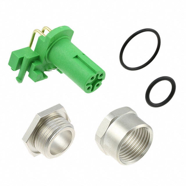
| 描述 | 重负荷电源连接器 PP75 HOUSING ONLY GREEN |
| 产品分类 | 电源连接器 |
| 产品手册 | |
| 产品图片 |
|
| rohs | 符合RoHS |
| 产品系列 | 重负荷电源连接器,Anderson Power Products 5916G6 |
| 产品型号 | 5916G6 |
| 产品种类 | 重负荷电源连接器 |
| 产品类型 | Housings |
| 商标 | Anderson Power Products |
| 商标名 | Powerpole |
| 工厂包装数量 | 25 |
| 电压额定值 | 600 V |
| 电流额定值 | 75 A |
| 系列 | PP75 |
| 线规量程 | 16-6 |


- 商务部:美国ITC正式对集成电路等产品启动337调查
- 曝三星4nm工艺存在良率问题 高通将骁龙8 Gen1或转产台积电
- 太阳诱电将投资9.5亿元在常州建新厂生产MLCC 预计2023年完工
- 英特尔发布欧洲新工厂建设计划 深化IDM 2.0 战略
- 台积电先进制程称霸业界 有大客户加持明年业绩稳了
- 达到5530亿美元!SIA预计今年全球半导体销售额将创下新高
- 英特尔拟将自动驾驶子公司Mobileye上市 估值或超500亿美元
- 三星加码芯片和SET,合并消费电子和移动部门,撤换高东真等 CEO
- 三星电子宣布重大人事变动 还合并消费电子和移动部门
- 海关总署:前11个月进口集成电路产品价值2.52万亿元 增长14.8%


PDF Datasheet 数据手册内容提取
SPEC Pak ® Sealed Power For Environmental Connections Marine | Wind Power | Lighting | Transportation | Pumps | Ground Support Machine Tool | Industrial Automation | Motor | Solar Power | Harsh Environments
Rugged and Sealed (IP68) Plugs and Receptacles The SPEC Pak® Mid Power is rugged and environmentally sealed (IP68). It leverages APP’s core Powerpole® flat wiping contact technology, offering power handling capabilities up to 80 amps at 600 volts with signal. The SPEC Pak® Mid Power shells are highly configurable. They accept up to four Powerpole® 75 (PP75) contacts and housings. They also accept up to 8 pin and socket auxiliary contacts providing the user signal and/or sequencing options. Assembly is made easy though the use of colored Powerpole® housings which can be matched to wire colors. They will ac- cept wire sizes ranging from 12 to 6 AWG [3.3 to 13.3 mm²]. SPEC Pak® Mid Power is highly configurable providing users with a multitude of flexible design solutions in a single interconnect. Auxiliary contacts are not visible in 1 the cut-a-way view. 2 4 3 8 5 7 Top of the latch is not visible from this view. 6 1 - Chemical & UV Resistant Ruggedized Shells 5 - Color Coded Powerpole® Housings to • Wire to Wire Configurations Match Wire Colors • Wire to Panel Configurations 6 - Stainless Steel Latches to Prevent 2 - Auxiliary Contacts for Signal and/or Accidental Unmating Sequencing (up to 8) 7 - IP68 Panel Mount Receptacle Gasket 3 - Power Contacts (up to 4) 8 - Sealing O-Ring Ensures (IP68) 4 - Sealing Gland to Ensures (IP68) Environmental Seal Environmental Seal - 2 - | www.andersonpower.com
.............................................. SPEC Pak® Shells Used With ............................................ SPEC Pak® Shell Powerpole® Power Auxiliary Contacts [1] Contacts & Housings (PowerMod® Series) Electrical Current Rating (Amperes) UL 1977 - 80 [2] 5 CSA (30° C Rise) - 50 [2] 5 Voltage Rating UL 1977 (AC/DC) - 600 600 Dielectric Withstanding (AC) - 3,000 - Contact Resistance Milliohms (average) - 0.200 [3] 2.000 [4] Hot Plug Amp Rating (UL 1977) 250 Cycles at 120V - 50 [5] Mechanical Environmental Seal IP rating IP68 - - Submersion (UL 50E) Pass - - Wire Size - 12 to 6 AWG 24 to 12 AWG - 3.3 to 13.3 mm² 0.50 to 2.5 mm² Operating Temperature -40° to 105° C -20° to 105° C -40° to 105° C -40° to 221° F -4° to 221° F -40° to 221° F Mating Cycles (no load) Silver Plated Contacts - 1,500 - Gold Plated Contacts - - 1,500 Contact Retention Force - > 50 lbf / 222 N - Insertion Force - 28 lbf Touch Safe (IEC 60529) - IP10 - Drop Test (UL50E) Pass - - Panel Break Off (EIA 394-97) Pass - - Crush Test (EIA 364-40B) Pass - - Materials Shell / Housing PC/PBT PC PC/PBT Powerpole® Holder PC/PBT - - Latch Stainless Steel - - Flammability (UL 94) V0 V0 V0 Weatherability (UL 764C) F1 F1 F1 Contacts Base - Copper Alloy Copper Alloy Plating - Silver Gold over Nickel NOTES: 1. Integral signal holders that holds up to 8 pins and 8 sockets. 2. Based on 6 AWG. 3. Based on 6 AWG 1-1/4” distance between probes. 4. Based on 20 AWG. 5. Hot Plug testing completed using individual Powerpole® housings and contacts, not installed in SPEC Pak® shells. For other industry tests and/or agency approvals, contact customer service. www.andersonpower.com | - 3 -
Product Selection Guide SPEC Pak® is a highly configurable environmentally sealed connector, that can be purchased as components in bulk for volume production, or pre-packaged as a kit. For convenience, follow the steps below to determine component or kit part numbers. | COMPONENT PART NUMBER GUIDE (FOR COMPONENT BULK PURCHASE) | Step 1: Select Shell Step 2: Select Wire Protection SK6-076C04 SK1-076C04 Plug Inline Receptacle * Define: Number of Wires Wire OD Wires - Discrete ____________ _____________ * Select Shell Style, - Bundled ____________ _____________ from page 6. * Select wire protection that will accommodate the number of wires and outer diameter (OD) of the wire used in your application, from page 6. SK2-076C04 Panel Mount Receptacle * Wire protection is required for use with inline receptacles and plugs to obtain IP68 seal. List Component Part Numbers Here: | KIT PART NUMBER GUIDE (FOR KITTED CONNECTOR PURCHASE) | Step 1 - (see page 6) ............................................................................................. Shell ........................................................................................ SPEC Pak® Series Shell Color Shell Style Shell Size Insert Arrangement (Select One) Dash S K 1 = Inline Receptacle - 076 C04 2 = Panel Mount Receptacle 6 = Straight Plug 9 = Receptacle Cover 9P = Plug Cover List Kit Part Number Here: Receptacle Kit Part Number: S K ___________________________ - 076 C04 Plug Kit Part Number: S K ___________________________ - 076 C04 - 4 - | www.andersonpower.com
Step 3: Select Housing Arrangement Step 4: Select Contacts Pin Auxiliary Contact Power Contact Socket Auxiliary Contact * Define: * Define: Number of Number of Number of Circuits Wire Gauge Wires Auxiliaries Contacts Housing Arrangement - Power _____________ __________ - AC Single Phase ___________ ____________ - Auxiliary _____________ __________ - AC 3 Phase ___________ ____________ - Other _____________ __________ - DC ___________ ____________ - Other ___________ ____________ Amps (continuous): ____ Max amps at ____ volts * Select housing arrangement colors appropriate for * Select power and/or auxiliary contacts appropriate your AC or DC application, from page 7. for your wire size (AWG or mm²), from page 7. List Component Part Numbers Here: Step 2 - (see page 6) Step 3 - (see page 7) Step 4 - (see page 7) Custom .................... Wire Protection .................... .. Housing Arrangement .. ........... Contacts ........... .... APP Content .... Number of Holes Cable Sealing Range (Select Two) Dash (Select One) (Select One) Dash 00 = None - 0 = Custom Configuration - Contact the factory PS = Plastic Single-hole A = AC Single Phase Custom Configuration PM = Plastic Multi-hole B = AC 3 Phase, 3 Wire C = DC Circuit, 4 Wire 00 = None Z = All Black 01 - 99 = Various Gland Types (See Page 6) 0 = Custom Configuration NOTE: Panel Mount Receptacle is always “00 00”. 70 = 1307 Contact for #6 AWG (13.3 mm²) 71 = Please inquire for #8 AWG (8.4 mm²) 72 = 5953 Contact for #10/12 AWG (3.3 to 5.3 mm²) __________ __________ - __________ __________ __________ __________ - __________ __________ www.andersonpower.com | - 5 -
Ordering Information PLUG PANEL MOUNT INLINE COVER SHELL KIT RECEPTACLE KIT RECEPTACLE KIT KIT Part Number & Description Part Number & Description Part Number & Description Part Number & Description SK6-076C04 SK2-076C04 SK1-076C04 SK9-076 - Plug shell - Panel mount receptacle shell - Inline receptacle shell Receptacle Cover Kit - Powerpole® holder - plug - Powerpole® holder - receptacle - Powerpole® holder - receptacle - Cover (IP68) with lanyard - Powerpole® holder retaining - Panel mount receptacle gasket - Powerpole® holder retaining screws M3.5 x 15mm - Powerpole® holder retaining screws M3.5 x 15mm SK9P-076 - Sealing Gland Nut screws M3.5 x 15mm - Sealing Gland Nut Plug Cover Kit (Sealing grommet sold separately) (Sealing grommet sold separately) - Cover (IP68) with lanyard HRoeltdaeinri ng PHwloiuthug s LSinahgtce hll es Receptacle PGaansekel t HRoeltdaeinri ng IRSnheliencelelp tacle Receptacle Cover Plug Cover with Screws Powerpole® Screws Interfacial seal Holder Holder Retaining Screws Plug Sealing Nut Receptacle Sealing Nut Powerpole® Powerpole® Holder Holder Panel Receptacle Shell Component Replacement Parts Part Number Description NOTE: 115129P1 Panel Mount Receptacle Gasket Mounting Hardware (4 each M4 or #8 screws) not included. H1120P53 Powerpole holder retaining screws M3.5 x 15mm Recommended torque for mounting hardware is 7-10 in-lbs. | WIRE PROTECTION - CABLE GLAND | Material Mechanical Torque Requirements Shell PBT/PC IP Rating IP68 Hand tighten. Using a 44 mm Sealing Grommet EPDM Operating Temperature wrench or strap wrench, tighten Flammability (UL 94) V0 (UL 1977) -40° to 105° C an additional 3/4 - 1 turn. Weatherability (UL 764C) F1 -40° to 221° F Color Black Thread Type Integrated into inline receptacle & plug shells Wire Protection Straight Plastic Single & Multi Hole Cable Gland Sealing Glands Number Cable Range Wire Wrench Size Protection Sealing Grommet Only (includes sealing grommet & wire protection nut) of Holes Outer Diameter mm (in) Sealing Nut Designation -------------------------------- Part Numbers ------------------------------------------------------ Minimum Quantity ................................................................................................................ 10 For use w i t h 10 ................................................................ 1 18.0 - 24.0 mm (0.79” - 0.85”) 44 PS 01 B02130P7 SK1-07 6C04 & PS1T40-24X For use with shell kit components 2 3.8 - 5.0mm (0.15” - 0.20”) 44 PM 21 B02130P12 SK6-07 6C04 PS2T40-5X purchased in bulk. 2 6.0 - 7.2mm (0.24” - 0.28”) 44 PM 22 B02130P11 PS2T40-7X 2 7.0 - 9.0mm (0.28” - 0.35”) 44 PM 23 B02130P10 PS2T40-9X ....................................................................................................................................................................... ................... 3 6.0 - 7.2mm (0.24” - 0.28”) 44 PM 32 B02130P5 PS3T40-7X 3 7.0 - 9.0mm (0.28” - 0.35”) 44 PM 33 B02130P4 PS3T40-9X . ................................. ...................................................... .............................. ................. .............. .................. ................... 4 3.8 - 5.0mm (0.15” - 0.20”) 44 PM 41 B02130P3 PS4T40-5X 4 6.0 - 7.2mm (0.24” - 0.28”) 44 PM 42 B02130P2 PS4T40-7X 4 7.0 - 9.0mm (0.28” - 0.35”) 44 PM 43 B02130P1 PS4T40-9X ................................................................................................................................................................................................................................................................................... - 6 - | www.andersonpower.com
C04 Housing Arrangement Configured with up to 4 PP75 Contacts - Up to 80 Amps | Standard Housing Arrangements | | TEMPERATURE CHART | E = Empty Mid Power SPEC Pak® 0 Custom Configuration Four Power Contacts / Eight Signal Contacts 5A 60 AC Single Phase A 5916G4 5916G5 50 5916G6 E C) AC 3 Phase, 3 Wire ure (° 40 B 5916G4 5916G5 at 30 er 5916G7 E mp e 20 T DC 2 Circuit, 4 Wire 10 C 5916G4 5916G4 5916G7 5916G7 0 0 10 20 30 40 50 60 70 80 All Black Amperes Applied Z 5916G4 5916G4 6 AWG 8 AWG 5916G4 5916G4 10 AWG 12 AWG Ordering Information PP75 Standard Power Contacts, Signal Contacts & Housings Spacer & Keying Accessory Description -------- Part Number -------- Description -------- Part Number -------- Minimum Quantity ..... 1000 100 .... Minimum Quantity .. 1000 100 ..... Red, Short 1399G23-BK 1399G23 Red 5916G7-BK 5916G7 Red, Long 1399G21-BK 1399G21 Green 5916G6-BK 5916G6 Black 5916G4-BK 5916G4 White 5916G5-BK 5916G5 Blue 5916-BK 5916 Yellow 5916G15-BK 5916G15 Orange 5916G14-BK 5916G14 Short Long Gray 5916G16-BK 5916G16 PP75 Silver Plated Wire Contacts Mating Contact Code Hand Pneumatic Type AWG mm² Force -- Part Numbers -- Designation Tool Tool Die Locator Minimum Quantity ............................... 1000 100 ........................ For use with 6 AWG Individual 6 13.3 Low 1307-BK 1307 70................. 1309G4 1387G1 1388G6 1389G6 Individual 8 8.4 Low Please inquire 71 ................................................................................... Individual 12 to 10 3.3 to 5.3 Low 5953-BK 5953 72 ................. For use with 12/10 AWG 1309G4 1387G1 1388G7 1389G6 Auxiliary Contacts (PowerMod® series) Type AWG mm² ---- Part Number --- Hand Hand Pnuematic Minimum Quantity….................. 500 50 ..... Tool Tool Locator Tool Locator Standard Length 7.7mm For use with pins Pin 24 to 20 0.50 to 0.75 PM16P2024S30 PM16P2024S30-50 Pin 20 to 18 0.75 to 1.00 PM16P1620S30 PM16P1620S30-50 Pin 16 to 14 1.00 to 1.5 PM16P1416S30 PM16P1416S30-50 Pin 12 2.50 PM16P12S30 PM16P12S30-50 Pre-Mate 9.3mm Pin 24 to 20 0.50 to 0.75 PM16P2024A30 PM16P2024A30-50 Pin 20 to 18 0.75 to 1.00 PM16P1620A30 PM16P1620A30-50 Pin 16 to 14 1.00 to 1.5 PM16P1416A30 PM16P1416A30-50 PM1000G1 TM0001 TL0001 TP0001 TL0001 Pin 12 2.50 PM16P12A30 PM16P12A30-50 Post-Mate 6.4mm Pin 24 to 20 0.50 to 0.75 PM16P2024C30 PM16P2024C30-50 Pin 20 to 18 0.75 to 1.00 PM16P1620C30 PM16P1620C30-50 Pin 16 to 14 1.00 to 1.5 PM16P1416C30 PM16P1416C30-50 Pin 12 2.50 PM16P12C30 PM16P12C30-50 ------------------------------------------------------------------------------------------------------------ For use with sockets Socket 24 to 20 0.25 to 0.50 PM16S2024S32 PM16S2024S32-50 Socket 20 to 16 0.50 to 1.30 PM16S1620S32 PM16S1620S32-50 PM1000G1 TM0001 TL0002 TP0002 TL0002 Socket 16 to 14 1.30 to 2.10 PM16S1416S32 PM16S1416S32-50 Socket 12 2.5 PM16S12S32 PM16S12S32-50 www.andersonpower.com | - 7 -
| PLUG MID POWER FOR PP75 HOUSINGS | Top View Front View Side View Mated View [ 3.73 ] [ 2.97 ] [ 3.09 ] [ 4.4 ] 111.0 94.7 75.5 99.0 Mated Length to Panel Receptacle [ 2.47 ] 62.8 | PANEL MOUNT RECEPTACLE MID-POWER FOR PP75 | Panel Cut Out Front View Side View Mated View [ 2.36 ] [ 3.19 ] [ 4.4 ] 111.0 60.0 81.0 Mated Length to [ 1.31 ] Panel Receptacle 33.2 [ 2.36 ] [ 3.19 ] 60.0 81.0 [ 0.98 ] 25.0 | INLINE RECEPTACLE MID-POWER FOR PP75 | Top View Front View Side View Mated View [ 3.76 ] [ 2.83 ] [ 6.9 ] 175.0 95.5 71.8 Mated Length to Plug [ 2.70 ] 68.6 [ 3.9 ] 100.0 | PLUG COVER KIT | | RECEPTACLE COVER KIT | Front View Side View Front View Side View [ 3.03 ] [ 2.79 ] 77.0 70.8 [ 2.52 ] [ 1.10 ] [ 2.47 ] [ 1.40 ] 63.9 28.0 62.8 35.5 © 2017 Anderson Power Products, Inc. All rights reserved. APP®, Anderson Power Products®, A®, SPEC Pak®, Powerpole® and the APP Logo are registered trademarks of Anderson Power Products, Inc. • All Data Subject To Change Without Notice 2017-0005 DS-MPSPAK REV 3 HEADQUARTERS: Anderson Power Products®, 13 Pratts Junction Road, Sterling, MA 01564-2305 USA T:978-422-3600 F:978-422-0128 • EUROPE: Anderson Power Products® Ltd., Unit 3, Europa Court, Europa Boulevard, Westbrook, Warrington, Cheshire, WA5 7TN United Kingdom T: +44 (0) 1925 428390 F: +44 (0) 1925 520203 • ASIA / PACIFIC: IDEAL Anderson Asia Pacific Ltd., Unit 922-928 Topsail Plaza, 11 On Sum Street, Shatin N.T., Hong Kong T:+(852) 2636 0836 F:+(852) 2635 9036 • CHINA: IDEAL Anderson Technologies (Shenzhen) Ltd., Block A8 Tantou Western Industrial Park, Songgang Baoan District, Shenzhen, PR. China 518105 T: +(86) 755 2768 2118 F: +(86) 755 2768 2218 • TAIWAN: IDEAL Anderson Asia Pacific Ltd., Taiwan Branch, 4F.-2, No.116, Dadun 20th St., Situn District, Taichung City 407, Taiwan (R.O.C.) T: +(886) 4 2310 6451 F:+(886) 4 2310 6460 • www.andersonpower.com