ICGOO在线商城 > 2708274
- 型号: 2708274
- 制造商: Phoenix Contact
- 库位|库存: xxxx|xxxx
- 要求:
| 数量阶梯 | 香港交货 | 国内含税 |
| +xxxx | $xxxx | ¥xxxx |
查看当月历史价格
查看今年历史价格
2708274产品简介:
ICGOO电子元器件商城为您提供2708274由Phoenix Contact设计生产,在icgoo商城现货销售,并且可以通过原厂、代理商等渠道进行代购。 提供2708274价格参考以及Phoenix Contact2708274封装/规格参数等产品信息。 你可以下载2708274参考资料、Datasheet数据手册功能说明书, 资料中有2708274详细功能的应用电路图电压和使用方法及教程。
| 参数 | 数值 |
| 产品目录 | |
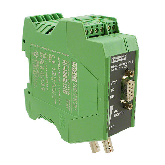
| 描述 | FIBER OPTIC CONVERTER DIN RAIL光纤发射器、接收器、收发器 PSI-MOSPROFIB/FO850E |
| 产品分类 | |
| 品牌 | Phoenix Contact |
| 产品手册 | http://www.phoenixcontact.com/us/products/2708274/pdf |
| 产品图片 |
|
| rohs | 符合RoHS无铅 / 符合限制有害物质指令(RoHS)规范要求 |
| 产品系列 | 光纤发射器、接收器、收发器,Phoenix Contact 2708274* |
| mouser_ship_limit | 该产品可能需要其他文件才能进口到中国。 |
| 数据手册 | |
| 产品型号 | 2708274 |
| 产品 | Converters |
| 产品种类 | 光纤发射器、接收器、收发器 |
| 其它名称 | 2708274-ND |
| 单位重量 | 185 g |
| 商标 | Phoenix Contact |
| 安装风格 | DIN Rail |
| 封装/箱体 | 106 mm x 35 mm x 99 mm |
| 峰值波长 | 850 nm |
| 工作电源电压 | 24 V |
| 工厂包装数量 | 1 |
| 应用 | PROFIBUS |
| 数据速率 | 12 MBd |
| 最大工作温度 | + 60 C |
| 最小工作温度 | - 20 C |
| 标准包装 | 1 |
| 波长 | 850 nm |
| 纤维类型 | Multimode |
| 连接器类型 | ST |
| 零件号别名 | PSI-MOS-PROFIB/FO_850_E PSIMOSPROFIBFO850E |

-LR-PC-6(40).jpg)


- 商务部:美国ITC正式对集成电路等产品启动337调查
- 曝三星4nm工艺存在良率问题 高通将骁龙8 Gen1或转产台积电
- 太阳诱电将投资9.5亿元在常州建新厂生产MLCC 预计2023年完工
- 英特尔发布欧洲新工厂建设计划 深化IDM 2.0 战略
- 台积电先进制程称霸业界 有大客户加持明年业绩稳了
- 达到5530亿美元!SIA预计今年全球半导体销售额将创下新高
- 英特尔拟将自动驾驶子公司Mobileye上市 估值或超500亿美元
- 三星加码芯片和SET,合并消费电子和移动部门,撤换高东真等 CEO
- 三星电子宣布重大人事变动 还合并消费电子和移动部门
- 海关总署:前11个月进口集成电路产品价值2.52万亿元 增长14.8%

PDF Datasheet 数据手册内容提取
PSI-MOS-PROFIB/FO... FO converter for PROFIBUS up to 12 Mbps Data sheet 101972_en_12 © PHOENIX CONTACT 2016-12-15 1 Description Features – Automatic data rate detection or fixed data rate setting The FO converters PSI-MOS-PROFIB/FO... convert cop- via DIP switches per-bound PROFIBUS-DP-interfaces to fiber optics. You can also use the devices in MPI networks (not in ring struc- – Data rate up to 12Mbps, protocol transparent tures). – Integrated optical diagnostics for continuous monitoring of fiber optic paths As a result of the simple and interference-free networking via fiber optics, bus cable short circuits only affect the actual – Floating switch contact for leading alarm generation in potential segment concerned. This increases overall avail- relation to critical fiber optic paths ability and improves flexibility in terms of the bus topology. – Cascadable star and tree structures can be created us- This prevents the negative effects of equipotential bonding ing bit retiming. currents and EMC interference on the bus lines. – Electrical isolation between all interfaces The termination devices PSI-MOS-PROFIB/FO...E con- – Supply voltage and data signals routed through a DIN vert a PROFIBUS interface to a FO cable. They are ideal for rail connector point-to-point connections. – Redundant power supply possible T-couplers PSI-MOS-PROFIB/FO...T convert to two fiber – Can be combined with the PSI copper repeater for optic cables. They can be used to create redundant bus to- PROFIBUS in a modular way using DIN rail connectors pologies for increased system availability. – PSI-MOS-PROFIB/FO...-SO versions with coated In addition, modular connection stations can be created PCB for increased resistance to salt-laden atmo- from both device versions. Devices with different transmis- spheres sion technologies (polymer, PCF, and fiberglass) can be freely combined within a connection station. WARNING: Explosion hazard when used in potentially explosive areas This device is a category 3 item of electrical equipment. Follow the instructions provided here during installation and observe the safety notes. Make sure you always use the latest documentation. It can be downloaded at phoenixcontact.net/products. This data sheet is valid for all products listed on the following page:
PSI-MOS-PROFIB/FO... 2 Table of contents 1 Description..................................................................................................................................1 2 Table of contents........................................................................................................................2 3 Ordering data..............................................................................................................................3 4 Technical data............................................................................................................................4 5 Safety regulations and installation notes.....................................................................................7 5.1 Installation notes............................................................................................................................................7 5.2 Installation in zone 2.......................................................................................................................................7 5.3 UL notes.........................................................................................................................................................7 6 Network structures......................................................................................................................8 7 Construction.............................................................................................................................10 7.1 Dimensions..................................................................................................................................................10 7.2 Block diagram..............................................................................................................................................10 7.3 Function elements........................................................................................................................................11 7.4 Idle setting....................................................................................................................................................13 7.5 Interfaces.....................................................................................................................................................13 8 Configuration............................................................................................................................14 8.1 Setting the DIP switches...............................................................................................................................14 8.2 Setting the data rate (DIP switch 1-4)...........................................................................................................15 8.3 Echo evaluation (DIP switch 5).....................................................................................................................15 8.4 Connection to fiber optic interfaces from third-party suppliers (DIP switch 5/6)............................................15 8.5 Redundancy function (DIP switch 7/9) .........................................................................................................16 8.6 Activating enhanced ring management (DIPswitch 7/9) .............................................................................16 8.7 Switching off the second fiber optics port (DIPswitch 8)..............................................................................17 8.8 Activate the FIBER CONTROL function (DIPswitch 10)..............................................................................17 8.9 Mixed operation of PSI-MOS and PSM-EG..................................................................................................17 9 Mounting...................................................................................................................................19 9.1 Installation in potentially explosive areas......................................................................................................20 9.2 Dismantling..................................................................................................................................................20 10 Supply voltage..........................................................................................................................21 10.1 Operation as a single device........................................................................................................................21 10.2 Operation in a connection station.................................................................................................................21 11 PROFIBUS interface.................................................................................................................22 12 Fiber optics interface (FO port).................................................................................................23 13 Switching output.......................................................................................................................24 14 Configuration rules....................................................................................................................25 14.1 Configuring the network parameters (PSI-MOS devices with 10-pos. DIP switch).......................................25 14.2 Configuring the network parameters (PSI-MOS devices with 8-pos. DIP switch).........................................28 101972_en_12 PHOENIX CONTACT 2/30
PSI-MOS-PROFIB/FO... 3 Ordering data Description Type Order No. Pcs./Pkt. FO converter with integrated optical diagnostics, alarm contact for PROFIBUS up to 12 Mbps, for 660 nm, for polymer/PCF fiber cable, FSMA Termination device with one fiber optic interface PSI-MOS-PROFIB/FO660E 2708290 1 T-coupler with two fiber optic interfaces PSI-MOS-PROFIB/FO660T 2708287 1 FO converter with integrated optical diagnostics, alarm contact for PROFIBUS up to 12 Mbps, for 850 nm, fiberglass cable, B-FOC (STR) Termination device with one fiber optic interface PSI-MOS-PROFIB/FO850E 2708274 1 T-coupler with two fiber optic interfaces PSI-MOS-PROFIB/FO850T 2708261 1 FO converter, as described above but with coated PCB for increased resistance to salt-laden atmospheres Termination device with one fiber optic interface PSI-MOS-PROFIB/FO850E-SO 2708711 1 T-coupler with two fiber optic interfaces PSI-MOS-PROFIB/FO850T-SO 2708614 1 Other FO converters Description Type Order No. Pcs./Pkt. FO converter with integrated optical diagnostics, alarm con- tact, for PROFIBUS up to 12 Mbps, 1300 nm, for fiberglass cable, SC duplex Multi-mode fiberglass cable, up to 25 km Single-mode fiberglass cable, up to 45 km Termination device with one fiber optic interface PSI-MOS-PROFIB/FO1300 E 2708559 1 T-coupler with two fiber optic interfaces PSI-MOS-PROFIB/FO1300 T 2708892 1 Accessories Description Type Order No. Pcs./Pkt. DIN rail power supply unit, primary-switched, slim design, MINI-SYS-PS 100-240AC/ 2866983 1 output: 24VDC/1.5A 24DC/1.5 DIN rail power supply unit, primary-switched, slim design, MINI-PS-100-240AC/24DC/ 2866653 1 output: 24VDC/1.5A, ATEX approval 1.5/EX End bracket CLIPFIX 35 3022218 50 DIN rail connector, power supply and data (2 per device) ME 17.5 TBUS1.5/5-ST-3.81GN 2709561 10 DIN rail connector, power supply only (2 per device) ME 17.5 TBUS1.5/PP000- 2890014 10 3.81BK Small, angled PROFIBUS plug with screw connection SUBCON-PLUS-PROFIB/SC2 2708232 1 Small, angled PROFIBUS plug with screw connection and SUBCON-PLUS-PROFIB/PG/ 2708245 1 additional PG connection SC2 Polymer fiber connectors (4 connectors in a set) PSM-SET-FSMA/4-KT 2799720 1 Polishing set for polymer fiber connectors (required to as- PSM-SET-FSMA-POLISH 2799348 1 semble polymer fiber connectors) Polymer fiber cable (fiber optic) for indoor installation PSM-LWL-KDHEAVY 2744319 1 FSMA PCF fiber connectors (4 connectors in the set) PSM-SET-FSMA/4-HCS 2799487 1 B-FOC (ST®) PCF fiber connectors (4 connectors in the set) PSM-SET-B-FOC/4-HCS 2708481 1 101972_en_12 PHOENIX CONTACT 3/30
PSI-MOS-PROFIB/FO... Accessories Description Type Order No. Pcs./Pkt. Tool set for PCF connectors (FSMA) (required for PCF con- PSM-HCS-KONFTOOL 2799526 1 nector assembly) Tool set for PCF connectors B-FOC (STR) (required for PSM-HCS-KONFTOOL/B-FOC 2708465 1 PCF connector assembly) Tool set for FSMA and SC-RJ connectors (polymer fiber) PSM-POF-KONFTOOL 2744131 1 PCF cable (fiber optic) for indoor installation PSM-LWL-HCS RUGGED-200/ 2799885 1 230 PCF cable (fiber optic) for outdoor installation PSM-LWL-HCSO-200/230 2799445 1 Fiber optic fiberglass cable for indoor installation PSM-LWL-GDM-RUGGED-50/ 2799322 1 125 Fiber optic fiberglass cable for outdoor installation PSM-LWL-GDO-50/125 2799432 1 Measuring instrument for fiber optic power measurement PSM-FO-POWERMETER 2799539 1 4 Technical data Power supply PSI-MOS-PROFIB/FO660... PSI-MOS-PROFIB/FO850... Power supply 18 V DC ... 30 V DC (via pluggable COMBICON screw terminal block) Maximum current consumption 130 mA Typical current consumption 100mA (24VDC) 120mA (24VDC) Electrical isolation (VCC // RS-485) Test voltage data interface/power supply 1.5 kV (50 Hz, 1 min.) rms Tightening torque 0.56 Nm ... 0.79 Nm PROFIBUS according to IEC 61158, RS-485, 2-wire, half duplex, automatic control Operation mode Half duplex Connection method D-SUB 9 socket Data format/coding UART (11 bits, NRZ) Data direction changeover Automatic Serial transmission speed ≤ 12 Mbps Transmission length ≤ 1200 m (with shielded, twisted-pair data line depending on the data rate) Transmission medium 2-wire twisted pair, shielded Output voltage 5 V DC (±0.25), 50 mA FO interface PSI-MOS-PROFIB/FO660... PSI-MOS-PROFIB/FO850... Connection method FSMA B-FOC (ST®) Wavelength 660 nm 850 nm Transmission length including 3 dB system reserve 70 m (with F-P 980/1000 800 m (with F-K 200/230 230dB/km with a quick mount- 10 dB/km with a quick mount- ing connector) ing connector) 400 m (with F-K.200/230 2600 m (with F-G 50/125 10dB/km with a quick mount- 2.5dB/km) ing connector) 3300 m (with F-G 62.5/125 3.0dB/km) Minimum transmission length 1 m with F-K 200/230; 8 dB/km 101972_en_12 PHOENIX CONTACT 4/30
PSI-MOS-PROFIB/FO... FO interface PSI-MOS-PROFIB/FO660... PSI-MOS-PROFIB/FO850... Minimum transmission power -3 dBm (980/1000 µm) -4.2 dBm (200/230 µm) -15.4 dBm (200/230 µm) -17.8 dBm (50/125 µm) -14.6 dBm (62.5/125 µm) Minimum receiver responsiveness -30 dBm -30 dBm (50/125 µm) Overrange receiver -3 dBm (980/1000 µm) -3 dBm (200/230 µm) Transmission protocol Transparent protocol to RS-485 interface General data Degree of protection IP20 Dimensions (W/H/D) 35 mm x 99 mm x 106 mm Weight 190 g (Termination device) 250 g (T-coupler) Enclosure material PA 6.6-FR, green Free fall according to IEC 60068-2-32 1 m Vibration resistance according to EN60068-2-6/ 5g, 150 Hz, 2.5 h, in XYZ direction IEC60068-2-6 Shock according to EN 60068-2-27/IEC 60068-2-27 15g, 11 ms period, half-sine shock pulse Air clearances and creepage distances DINEN60664-1/VDE0110-1, DINEN50178, DINEN60950 Bit distortion, input ± 35 % (permissible) Bit distortion, output < 6.25 % Bit delay in standard operation (DIP7 = OFF) < 1 bit (configurable) Bit delay in redundancy mode (DIP 7 = ON) 11 bit Switching output, switching voltage, maximum 60 V DC 42 V AC Switching output, limiting continuous current 0.46 A MTTF times PSI-MOS- PSI-MOS- PSI-MOS- PSI-MOS- PROFIB/ PROFIB/ PROFIB/ PROFIB/ FO660E FO660T FO850E FO850T MTTF (Mean Time To Failure) SN 29500 standard, 243 years 213 years 247 years 212 years temperature 25 °C, operating cycle 21% (5 days per week, 8 hours per day) MTTF (Mean Time To Failure) SN 29500 standard, 178 years 150 years 200 years 150 years temperature 40 °C, operating cycle 34.25% (5 days per week, 12 hours per day) MTTF (Mean Time To Failure) SN 29500 standard, 110 years 86 years 130 years 86 years temperature 40 °C, operating cycle 100% (7 days per week, 24 hours per day) Ambient conditions Ambient temperature (operating) -20 °C ... 60 °C Ambient temperature (storage/transport) -40°C ... 85°C Permissible humidity (operation) 30% ... 95% (non-condensing) 101972_en_12 PHOENIX CONTACT 5/30
PSI-MOS-PROFIB/FO... Approvals Conformance CE-compliant, EAC Free from substances that would hinder coating with paint According to VW-AUDI-Seat central standard P-VW 3.10.7 57 or varnish 65 0 ATEX (Please follow the special installation instructions in II 3 G Ex nA nC IIC T4 Gc X the documentation) II (2) G [Ex op is Gb] IIC (PTB 06 ATEX 2042 U) II (2) D [Ex op is Db] IIIC (PTB 06 ATEX 2042 U) UL, USA/Canada Class I, Zone 2, AEx nc IIC T5 Class I, zone 2, Ex nC nL IIC T5 X Class I, Div. 2, Groups A, B, C, D PROFIBUS interoperability Tested by independent PNO test laboratory (PN059-485-01) ABB certification: Industrial IT enabled This certification is a trademark of ABB. Shipbuilding approval DNV Conformity with EMC Directive 2014/30/EU Noise immunity according to EN 61000-6-2 Electrostatic discharge EN 61000-4-2 Contact ± 6 kV discharge Air discharge ± 8 kV Comment Criterion B Electromagnetic HF field EN 61000-4-3 Field strength 10 V/m Comment Criterion A Fast transients (burst) EN 61000-4-4 Input ± 2 kV Signal ± 2 kV Comment Criterion B Surge current loads (surge) EN 61000-4-5 Input ± 0.5 kV Signal ± 1 kV Comment Criterion B Conducted interference EN 61000-4-6 Voltage 10 V Comment Criterion A Noise emission according to EN 61000-6-4 Noise emission EN 55011 class A industrial area of application Criterion A Normal operating behavior within the specified limits Criterion B Temporary adverse effects on the operating behavior, which the device corrects automatically 101972_en_12 PHOENIX CONTACT 6/30
PSI-MOS-PROFIB/FO... 5 Safety regulations and installation notes 5.1 Installation notes • The switches of the device that can be accessed may only be actuated when power to the device is discon- WARNING: nected. Observe the following safety notes when using • The device is designed exclusively for operation with the FO converter. safety extra-low voltage (SELV) according to IEC60950/EN 60950/VDE 0805. The device may only • The category 3 device is suitable for installation in be connected to devices that meet the requirements of Zone2 potentially explosive areas. It meets the require- EN 60950. ments of EN60079-0:2012+A11:2013 and EN60079- 15:2010. 5.2 Installation in zone 2 • The FO components of type PSI-MOS transmitter con- trol 660 or 850 are a part of the module. The fibre optics WARNING:Explosion hazard when used in interface is used for optical communication with devices potentially explosive areas used in the potentially explosive area of zone 1 or Make sure that the following notes and instruc- zone21. It is used in accordance with the EC examina- tions are observed. tion certificate. • Installation, operation, and maintenance may only be • Observe the specified conditions for use in potentially carried out by qualified electricians. Follow the installa- explosive areas! tion instructions as described. When installing and op- • Install the device in a suitable, approved housing (with erating the device, the applicable regulations and at least IP54 protection) that meets the requirements of safety directives (including national safety directives), EN 60079-15. For this purpose, observe the require- as well as the general codes of practice, must be ob- ments of IEC 60079-14 / EN 60079-14. served. The safety data is provided in the packing slip • Only connect devices to the supply and signal circuits in and on the certificates (conformity assessment, addi- zone2 that are suitable for operation in Ex zone2 and tional approvals where applicable). for the conditions at the installation location. • The device must not be opened or modified apart from • In potentially explosive areas, only snap the device onto the configuration of the DIP switches. or off the DIN rail connector and connect/disconnect ca- • Do not repair the device yourself; replace it with an bles when the power is disconnected. equivalent device instead. Repairs may only be carried • The device must be stopped and immediately removed out by the manufacturer. The manufacturer is not liable from the Ex area if it is damaged, was subjected to an for damage resulting from non-compliance. impermissible load, stored incorrectly or if it malfunc- • The IP20 degree of protection (IEC 60529/EN 60529) of tions. the device is intended for use in a clean and dry envi- • Connection to the D-SUB interface is only permitted if ronment. Do not subject the device to mechanical and/ the screw connection is tightened. or thermal loads that exceed the specified limits. 5.3 UL notes PROCESS CONTROL EQUIPMENT FOR HAZARDOUS LOCATIONS 31ZN A) This equipment is suitable for use in Class I, Zone 2, AEx nC IIC T5, Ex nC nL IIC T5 X; and Class I, Division 2, Groups A, B, C and D or non-hazardous locations only. B) WARNING - EXPLOSION HAZARD - substitution of components may impair suitability for Class I, Zone 2/Division 2. C)WARNING - EXPLOSION HAZARD - do not disconnect equipment unless power has been switched off or the area is known to be non-hazardous. D)This device must be installed in an enclosure rated IP54 and used in an area of not more than pollution degree 2. 101972_en_12 PHOENIX CONTACT 7/30
PSI-MOS-PROFIB/FO... 6 Network structures Linear structures Max.31 The PSI-MOS-PROFIB/FO... system can be used to create network structures that are tailored to the relevant applica- E tion. To create the illustrated network structures you will need: FO – T-coupler (PSI-MOS-PROFIB/FO...T) Max.31 – Termination devices (PSI-MOS-PROFIB/FO...E) T Point-to-point connections FO Max.31 Max.31 Max.31 T E T FO Linearstructure FO You can network several devices to form a line structure. – Termination devices are used at the beginning and end of the fiber optic path. E T – T-couplers with two fiber optic ports are used along the Max.31 Max.31 line. Star structures Point-to-pointconnection Redundant point-to-pointconnection You can use two termination devices to easily convert a data Max.31 link from copper cable to fiber optics. For increased availability, the point-to-point connection can T T E ... also be designed redundantly. To do so, you will need two T-couplers. FO E E E E E Max.31 Starstructure You can also network PROFIBUS devices in a star struc- ture. To do so, connect several T-couplers and termination devices to an active star coupler. You can interconnect up to ten devices for each star cou- pler. Cross-wiring for the RS-485 data and the power supply is provided by the DIN rail connector. 101972_en_12 PHOENIX CONTACT 8/30
PSI-MOS-PROFIB/FO... Tree structures max.31 T T ... FO max.31 max.31 max.31 max.31 T T ... T T ... T T ... T T ... Treestructure FO You can cascade line and star structures to create complex tree structures, including in a redundant version if required. The maximum number of devices that can be cascaded is only limited by the timing response of the bus system used due to the bit retiming of the FO converter. Redundant ring structures max.31 ........ T max.31 max.31 T T ........ ........ FO T max.31 RedundantFOring ........ If a system has increased requirements in terms of transmis- sion reliability and availability, redundant ring structures can be created. If a fiber optic subsection in this topology breaks down (broken fiber), all the other devices can still be ac- cessed. In MPI networks, redundant ring structures cannot be created. In the redundant ring, mixed operation of PSI-MOS with FOinterfaces from other manufacturers is not permitted. 101972_en_12 PHOENIX CONTACT 9/30
PSI-MOS-PROFIB/FO... 7 Construction 7.1 Dimensions 35 106 OPSrdI-.M NOoS. 2-P7R 0O8F 2IB87/FO 660T VCC TD RD 9 9 FO SIGNAL ERR ERR A B Figure1 Housing dimensions 7.2 Block diagram N 24V (1) DC O gn TD BIC 0V (2) DC FO Line FO PortA M 11 (3) Retiming rd RD O Alarm ERRA C 12 (4) Line Diagnostics PortA V (6) PP CTRL UB GND (5) Bus Management FDuantac tRioante/ S D- Data B (3) ye DataA(8) gn Retiming Line Diagnostics Port B TD FO Line FO Port B∗) RD Retiming rd ERR B 24 V 0 V GND Data Data A B DIN Rail Connector ∗) Only for PSI-MOS-PROFIB/FO...T Figure2 Block diagram (port B only with T-couplers PSI-MOS-PROFIB/FO...T) 101972_en_12 PHOENIX CONTACT 10/30
PSI-MOS-PROFIB/FO... 7.3 Function elements 1 2 3 4 5 6 7 OPSrdI-.M NOoS. 2-P7R 0O8F 2IB87/FO 660T 8 VCC TD 9 RD 15 10 16 FO SIGNAL 11 17 ERR ERR A B 12 18 13 19 14 20 Figure3 Function elements 1 24 V DC supply voltage 2 0 V DC supply voltage 3 N/C contact, connection 11 4 N/C contact, connection 12 5 D-SUB 9 PROFIBUS interface 6 LED VCC Supply voltage 7 LED TD Dynamic transmission data to D-SUB 8 LED RD Dynamic receive data to D-SUB 9 LED Port A FO signal 10 LED Port A FO signal 11 LED Port A FO signal 12 LED Port A ERR 13 Fiber optic transmitter, port A 14 Fiber optic receiver, port A Port B only with T-couplers PSI-MOS-PROFIB/FO...T: 15 LED Port B FO signal 16 LED Port B FO signal 17 LED Port B FO signal 18 LED Port B ERR 19 Fiber optic transmitter, port B 20 Fiber optic receiver, port B 101972_en_12 PHOENIX CONTACT 11/30
PSI-MOS-PROFIB/FO... Diagnostic and status indicators LED Color Meaning VCC Green On: Transmission speed detected or set Flashing (1Hz): No valid transmis- sion speed detected (autobaud set- ting) TD Yellow Data is sent to the PROFIBUS inter- face (D-SUB 9). RD Green Data is received at the PROFIBUS interface (D-SUB 9). LED indicators of the FO interface The quality of the path is determined using the incoming op- tical power P and displayed using the LED bar graphs. In opt the default setting, the DIP switch 6 is set to OFF (INVERSE). In the idle state (rest period between transmit- ting data), the transmitters switch to permanent light to en- able continuous fiber optic diagnostics. If you switch DIP 6 to ON (NORM), the echo evaluation (DIP5 = OFF) is available as diagnostics. If you switch the echo evaluation off (DIP 5 = ON), fiber optic diagnostics are not available. DIP ON OFF (default setting) 5 MIXED - 6 STANDARD INVERSE Logic 1 = Light off Logic 1 = Light on LED Receive signal Optical power P opt FO signal Green Receiving power is very good Significantly greater than system reserve Green Receiving power is good Still greater than system reserve Yellow Receiving power is critical P has reached the system reserve. opt ERR Red Receiving power is insufficient, P has sapped the system reserve/ opt broken fiber broken fiber As soon as the system reserve is reached, only the yellow LED remains lit. At the same time, the signaling relay drops and the switching output opens. Data communication is still possible. In "Redundant ring" operating mode, the affected FO port is already switched off when the LED goes to yellow to prevent any risk of data corruption. 101972_en_12 PHOENIX CONTACT 12/30
PSI-MOS-PROFIB/FO... 7.4 Idle setting During the idle phase, fiber optic interfaces return to an idle setting defined by the manufacturer. This idle setting may vary for different manufacturers and devices. As fiber optic interfaces can only be operated to- gether if they have the same idle setting, this should be ob- served in mixed operation with third-party devices (see "Connection to fiber optic interfaces from third-party suppli- ers (DIP switch 5/6)" on page15). For PSI-MOS, the idle setting is specified as "Light on" (cor- responds to "Logic 1"). When connecting third-party devices, observe the receiver sensitivity and overrange limits of the fiber optic interfaces. 7.5 Interfaces The devices have three or four interfaces for the PROFIBUS signal: – Electrical interface (D-SUB) – DIN rail connector – FO port A – Fiber optics port B (only with T-couplers PSI-MOS-PROFIB/FO...T) All interfaces communicate with one another with the same rights. If a signal is present at one of the interfaces, this sig- nal is also available to all other interfaces. FO port A DIN rail D-SUB connector FO port B Figure4 Communication between the interfaces 101972_en_12 PHOENIX CONTACT 13/30
PSI-MOS-PROFIB/FO... 8 Configuration Changes to the default settings are only required in the fol- A lowing cases: – Operation with fixed transmission rate (default setting: automatic data rate detection) – Operation in a redundant ring B – Operation of a PSI-MOS-PROFIB/FO...T T-coupler with only one fiber optic port (switch off fiber optic Ord.M-NOoS.-2P7R0O8F2IB87/FO 660 T portB) VCC TD RD – Direct connection to fiber optic interfaces from other manufacturers ERRFSOIGNAELRRB A – Mixed operation of PSI-MOS with the old PSM-EG se- ries. Usually, you must adjust the differing idle settings of the two series. A – Mixed operation of PSI-MOS with 8-pos. and 10-pos. DIP switches. Devices with 10-pos. DIP switches have Figure5 Opening the housing been supplied since April 2006 and offer enhanced functions. • Release the housing cover using a screwdriver (A). In all other cases, you can operate the devices using the de- • Then carefully pull the printed-circuit board out of the fault settings. housing as far as possible (B). 8.1 Setting the DIP switches By default upon delivery, all DIP switches are in the "OFF" position. NOTE:Electrostatic discharge The module contains components that can be damaged or destroyed by electrostatic discharge. Wscahhrayer gnse ah f(aeEntySd Dplinr)e gac ctahcueot irdodeninvsgi ca tego,a EoinbNss t6e e1rlve3ec4 tt0rho-e5s -nt1ae tacicne dds i-s- 123456789O1N0 IEC 61340-5-1. DIP S1...S10 Select the operating mode only when the power is disconnected! The change is activated after re- newed power up. Figure6 DIP switch 101972_en_12 PHOENIX CONTACT 14/30
PSI-MOS-PROFIB/FO... Echo evaluation (DIP 5 = "OFF") is used to detect broken DIP ON OFF (default setting) fibers for the devices. During the idle phase (rest period be- tween transmitting data), the fiber optics between directly 1 connected devices are monitored for broken fibers. 2 Data rate (see table below) If there is a broken fiber, the respective FO fiber is switched 3 off, the error LED is set and the switching output is activated. 4 If the default setting for DIP 6 = "OFF" (INVERSE) is used, 5 MIXED - echo evaluation is switched off because the built-in diagnos- 6 STANDARD INVERSE tics (FO signal) permanently evaluates the received signal 71 REDUNDANCY - and therefore also detects a broken fiber. 81 END NEXT In a redundant ring (DIP 7 = "ON"), echo evaluation is al- 9 COMPATIBILITY - ways available, regardless of DIP switches 5 and 6. 10 FIBER CONTROL - You must always switch off the echo evaluation in the follow- 1 No function for PSI-MOS-PROFIB/FO...E termination devices ing operation cases: – Operation with data rates more than 1.5 Mbps (e.g. 8.2 Setting the data rate (DIP switch 1-4) 3Mbps), since a broken fiber could be detected with long FO fibers due to the correspondingly long cable The devices are equipped with automatic data rate detec- times. tion. If necessary, you can also specify a fixed transmission rate, which considerably reduces the initialization time of the – Mixed operation of PSI-MOS with FO interfaces from whole system. third-party suppliers (see chapter "Mixed operation of PSI-MOS and PSM-EG" on page17). • Set the transmission speed using the DIP switches. = ON DIP 1 DIP 2 DIP 3 DIP 4 8.4 Connection to fiber optic interfaces from third- Data rate [kbps] party suppliers (DIP switch 5/6) Autobaud During the idle phase, fiber optic interfaces return to an idle 12000 setting defined by the manufacturer. This idle setting may 6000 vary for different manufacturers and devices. As fiber optic 3000 interfaces can only be operated together if they have the same idle setting, this should be set using the DIP switches. 1500 For mixed operation of PSI-MOS with fiber optic interfaces 500 from other manufacturers, observe the following specifica- 187.5 tions: 93.75 • Deactivate the echo evaluation. 45.45 To do this, set DIP 5 to "ON". 19.2 • Check the idle setting for the third-party interface: 9.6 – Logic 1 = Light off or – Logic 1 = Light on 8.3 Echo evaluation (DIP switch 5) • If necessary, adjust the idle setting of PSI-MOS with Echo evaluation is useful for the mixed operation of DIP6. PSI-MOS and PSM-EG devices (older generation of DIP ON OFF (default setting) PhoenixContact fiber optic converters). Although PSM-EG 5 MIXED - devices offer echo evaluation, they do not offer the perma- nent diagnostics (FO signal) provided by PSI-MOS devices. 6 STANDARD INVERSE Therefore, the echo evaluation of the FO fibers is monitored. Logic 1 = Light off Logic 1 = Light on For additional information about the configuration of devices in mixed operation, please refer to Section "Mixed operation of PSI-MOS and PSM-EG" on page17. 101972_en_12 PHOENIX CONTACT 15/30
PSI-MOS-PROFIB/FO... In the "OFF" position, continuous measurement of the re- For path structures, activating the redundancy function re- ceived optical power is available. The reception quality is sults in the affected fiber optic port being switched off in the displayed by means of a 4-level bar graph (FO signal). In event of a weak fiber optic signal (yellow LED) and thus these operating conditions, the echo evaluation is automat- causes the subsequent part of the network to fail. ically shut off. In order to eliminate the ring length limits and the maximum In the "ON" position, continuous measurement of the re- transmission rate of 1.5 Mbps, an expanded redundancy ceived optical power is not available. The 4-level bar graph management was implemented in PSI-MOS. The expanded is switched off. If echo evaluation is also switched off (DIP 5 redundancy management is only used for T-couplers, since = "ON"), broken fiber detection is not available either. In this it is not possible to create a redundant ring with termination combination, the PSI-MOS devices do not have any diag- devices. nostics of the fiber optic path. The new redundancy management solution is based on the parameterization of a non-existent device in STEP 7®. This For mixed operation with devices of other manu- means that there are no limits in terms of the ring length. facturers, observe the receiver sensitivity and overrange limits of the fiber optic interfaces. To ensure compatibility with PSI-MOS devices that use the old redundancy management solution, an additional DIP In the redundant ring, mixed operation with FO in- switch (DIP 9 "COMPATIBILITY") has been added. terfaces of other manufacturers is not permitted. PSI-MOS devices with the new redundancy management solution have a 10-pos. DIP switch range, which makes it If DIP 6 is set to "ON", the FO diagnostics are not easy to distinguish between them and PSI-MOS devices available via the LED bar graphs. with the old redundancy management solution (8-pos. DIP The LED bar graph can light up at high transmis- switch range). sion speeds or flash at low transmission speeds. • During mixed operation of both PSI-MOS series in a re- This display does not correspond to continuous dundant ring, set DIP switch 7 and DIP switch9 to ON. evaluation of the optical power. = ON DIP 7 DIP 9 8.5 Redundancy function (DIP switch 7/9) 8-pos. - 10-pos. The redundancy function is only intended for use • Set the other switches according to your application. in the "redundant ring" network structure (see Page9). 8.6 Activating enhanced ring management • For path structures (point-to-point, linear, (DIPswitch 7/9) star, etc.), switch off the redundancy function (DIP 7 = OFF). The expanded ring management can only be used when only PSI-MOS devices with 10-pos. When you activate the redundancy function, the corre- DIP switches are used. sponding FO port is switched off automatically as soon as the receive quality reaches "System reserve reached" (only If DIP 9 is left set to "OFF" and DIP 7 is set to "ON", the fol- the yellow and red LEDs are lit). This enables you to prevent lowing functions are available in the redundant ring: any data corruption. – Increase maximum transmission speed from 1.5 Mbps When the fiber optic ports are switched off, the red ERR to 12 Mbps LED lights up on the affected port for both termination de- – No more restrictions regarding the maximum possible vices. In the redundant ring, data communication continues ring length via the second fiber optic port after the first fiber optic port is – No more restrictions regarding the maximum possible switched off. number of devices 101972_en_12 PHOENIX CONTACT 16/30
PSI-MOS-PROFIB/FO... 8.7 Switching off the second fiber optics port Diagnostics in mixed operation (DIPswitch 8) In mixed operation, the function of the diagnostic evaluation If you do not use the fiber optics port B with T-couplers depends on the switch settings of the devices. PSI-MOS-PROFIB/FO...T, you have to switch it off. Other- Usually, PSM-EG devices and PSI-MOS devices are only wise the red LED will light up, "ERR". combined in the case of exchange or replacement. There- • Set DIP 8 to "ON" (END). fore the following is based on a given setting of the PSM-EG devices with the PSI-MOS devices being adjusted to this. 8.8 Activate the FIBER CONTROL function If the idle setting is defined as "Light off" for PSM-EG (DIP 6 (DIPswitch 10) set to "OFF"), set DIP 6 to "ON" for PSI-MOS. The FO signal is thus no longer available to the PSI-MOS devices and di- If the devices are operated in the redundant ring agnostics is limited to the detection of broken fibers. If the (DIP7 = ON), DIP switch 10 is without function. idle setting is defined as "Light on" for PSM-EG (DIP 6 set to If you wish to interrupt transmission of the telegrams be- "ON"), set DIP 6 to "OFF" for PSI-MOS. tween two PSI-MOS devices in both directions of the fiber If broken fiber detection is activated for PSM-EG (DIP 7 set optics path in the event of a failure of one optical fiber, acti- to "ON"), set DIP 5 to "OFF" for PSI-MOS. If broken fiber de- vate the FIBER CONTROL function. tection is deactivated for PSM-EG (DIP 7 set to "OFF"), set • To do this, set DIP 10 to "ON". DIP 5 to "ON" for PSI-MOS. If a fiber break is now detected, the PSI-MOS device If broken fiber detection is deactivated and the idle setting is switches its optical transmitters to permanent light. Now, defined as "Light off", diagnostics are not available for the telegrams will no longer be transmitted on both optical fi- fiber optic path. bers. Overload or underload of the FO interfaces Once the received optical power is sufficient, the device au- tomatically resends the received telegram. In rare cases (usually in the case of very short fiber optic connections of just a few meters), an overload of the Activate this function on all PSI-MOS devices that PSI-MOS devices may occur in mixed operation. This is due are connected directly to each other via fiber optic to the highly sensitive PSI-MOS receivers, which cover paths. large ranges but can be overloaded on very short fiber optic paths (of just a few meters). 8.9 Mixed operation of PSI-MOS and PSM-EG When overloads occur, it is possible to increase the attenu- Mixed operation of the old PSM-EG series with the new ation via a patch cable with FO coupling in order to enable PSI-MOS is generally possible. Note the following settings flawless operation. and restrictions: In mixed operation, observe the following ranges: Configuring devices Fiber Wavelength Maximum range Glass 50/125 850 nm 1600 m The setting of the DIP switch depends on the requirements Glass 62.5/125 850 nm 2200 m of the application. PCF Not permissible for PSM-EG • Set the same idle setting for all devices in the system. POF 660 nm 70 m • On PSI-MOS device of the latest generation with 10-pos. DIP switches, switch the DIP switch 9 to "ON". 101972_en_12 PHOENIX CONTACT 17/30
PSI-MOS-PROFIB/FO... DIP FO diag- Switching off Echo Restrictions Operation mode Third-party = ON nostics the FO port evalua- connection / X = any position tion Mixed operation 5 6 7 8 9 10 X X Continu- None None None Line/Star/Tree Third-party cou- ous pler without echo function with "Light on" idle setting X Continu- None Activated Path length Line/Star/Tree Third-party cou- ous pler with echo function and "Light on" idle setting X X None None Activated Restriction of Line/Star with – the path "Light off" idle set- length de- ting pending on the transmis- sion speed X X None None None None Line/Star with Third-party cou- "Light off" idle set- pler without echo ting with "Light off" idle setting X X Continu- Yes, at low None Redundancy stan- – ous receiving dard operating power mode. Redun- X X Continu- Yes, at low Cannot Ring length dancy mode with For mixed opera- ous receiving be fiber optic diag- tion with different power switched nostics, path moni- generations of off1 toring, and PSI-MOS devices enhanced redundancy management X X X Continu- No switching None None Line/Star/Tree – ous off during a fiber break; telegrams will no longer be transmitted. 1 If DIP 7 (REDUNDANCY) is in the "ON" position and DIP 8 (END) is in the "OFF" position, the system switches automatically to the "Light on" idle setting with echo evaluation. However, if fiber optic port B is switched off by setting DIP 8 to "ON" (END), DIP 7 (REDUNDANCY) has no function. 101972_en_12 PHOENIX CONTACT 18/30
PSI-MOS-PROFIB/FO... 9 Mounting Combined assembly CAUTION:Electrical voltage The device is only intended for operation with A SELV according to IEC 60950/EN 60950/ VDE 0805. NOTE:Device damage Only mount and remove devices when the power supply is disconnected. B C NOTE:Malfunction Connect the DIN rail with the protective earth via a grounding terminal block. The devices are grounded when they are snapped onto the DIN rail (installation according to PELV). This ensures that the shielding is effective. Con- nect protective earth ground with low impedance. Figure8 Combined assembly Mounting as single device The DIN rail connector is used to bridge the power supply and communication. • Connect the DIN rail connectors for a connection sta- tion (Order No. 2709561, 2 per device). • Push the connected DIN rail connectors onto the DIN rail. • Place the device onto the DIN rail from above. • Push the front of the device toward the mounting sur- face until it audibly snaps into place. A connection station must not consist of more than ten de- vices. In this case, note the snap-on direction of the device and DIN rail connector: Figure7 Mounting on a DIN rail snap-on foot below and connector part left! • To avoid contact resistance, use only clean, corrosion- free 35 mm DIN rails in accordance with DIN EN 60715. • Install an end bracket next to the left-hand device to prevent the devices from slipping. • Place the device onto the DIN rail from above. • Push the front of the device toward the mounting sur- face until it audibly snaps into place. • Snap the other devices that are to be contacted onto the DIN rail next to one another. 101972_en_12 PHOENIX CONTACT 19/30
PSI-MOS-PROFIB/FO... 9.1 Installation in potentially explosive areas 9.2 Dismantling • Push down the locking latch using a screwdriver, WARNING:Explosion hazard when used in needle-nose pliers or similar. potentially explosive areas • Pull the bottom edge of the device slightly away from Observe the safety notes in Section 5 „Safety reg- the mounting surface. ulations and installation notes“ . • Pull the device diagonally upward from the DIN rail. Areas with a danger of gas explosions • When removing a complete connection station, also remove the DIN rail connectors. The devices are suitable for use in zone 2. Devices that are installed in zone 1 can be connected to the fiber optics inter- face. The fiber optic interface is an associated item of equip- ment with protection type "Exopis". Area with a danger of dust explosions The device is not designed for use in atmospheres with a danger of dust explosions. If dust is present, install the device in suitable, approved housing. When installed outside of areas with a danger of dust explo- sions, devices installed in zone 22 or 21 can also be con- nected to the fiber optic interface. Zone1 Zone2 Gasatmosphere Safearea POTREAVSrdI-.DCRMDNOoRCS.FS2-R7OIS0GRTO48ES8NR354N0W8M05.2A/FOLEB6R60TR POTREAVSrdI-.DCRMDNOoRCS.FS2-R7OIS0GRTO48ES8NR354N0W8M05.2A/FOLEB6R60TR FO FO Exopis [Exopis] [Exopis] XII2G XII(2)G XII(2)G Zone21 Zone22 Dustatmosphere Safearea POSrdI-.MNOoS.2-R7S0488350W02/FO660T TREAVDCRDRCFSOIGRTOESNR4N8M5.ALEBRR FO FO Exopis Exopis [Exopis] XII2D XII3D XII(2)D Figure9 Installation in potentially explosive areas 101972_en_12 PHOENIX CONTACT 20/30
PSI-MOS-PROFIB/FO... 10 Supply voltage 10.2 Operation in a connection station NOTE:Device damage CAUTION:Electrical voltage – The maximum current load in a connection The device is only intended for operation with station must not exceed 2A. SELV according to IEC 60950/EN 60950/ – A connection station must not consist of more VDE 0805. than ten devices. When the devices are operated in a connection station, the 1 2 3 4 supply voltage must only be supplied to the first device in the station. The remaining devices are supplied via the DIN rail 5 connector. 6 A second power supply unit can be used to create a redun- 7 OPSrdI-.M NOoS. 2-P7R 0O8F 2IB87/FO 660T dant supply concept. 8 VCC TD 9 RD 15 10 16 FO SIGNAL 11 17 ERR ERR A B 12 18 24 V 0 V 24 V 0 V 24 V 0 V 13 19 14 20 1 24 V DC supply voltage 2 0 V DC supply voltage Figure10 Individual and redundant supply 10.1 Operation as a single device Using the system power supply unit • Supply voltage to the device via the terminals 1 (24 V) Alternatively, the connection station can be connected to a and 2 (0 V). system power supply unit. • Connect a system power supply to two DIN rail connec- tors on the left of the group. (MINI-SYS-PS-100-240AC/24DC/1.5, Order No. 2866983 or MINI-PS100-240AC/24DC/1.5/EX, Order No. 2866653 and two DIN rail connectors, Order No. 2709561) 101972_en_12 PHOENIX CONTACT 21/30
PSI-MOS-PROFIB/FO... 11 PROFIBUS interface Figure11 PROFIBUS interface • Use an approved connector (e.g. SUBCON-PLUS- PROFIB, see Page3) to connect the bus cable to the D-SUB connection on the PSI-MOS device. • If the FO converter is used at the beginning or end of an electrical PROFIBUS segment, activate the termination in the connector. NOTE:Malfunction The maximum length of the RS-485 cables de- pends on the transmission speed. Do not exceed the following maximum values. Transmission speed Range [m] [kbps] 187.5 1000 500 400 1500 200 12000 100 PIN Signal Meaning 3 RxD/TxD-P Received/sent data, positive, B-cable 5 DGND Data transmission potential (reference potential to VP) 6 VP 5 V auxiliary voltage output (P5V), max. 50 mA 8 RxD/TxD-N Received/sent data, negative, A-cable 101972_en_12 PHOENIX CONTACT 22/30
PSI-MOS-PROFIB/FO... 12 Fiber optics interface (FO port) B-FOC (ST®) connection (PSI-MOS-PROFIB/FO850...) WARNING:Danger of eye injuries During operation, do not look directly into the transmitter diodes or use optical aids to look into the fiberglass! The infrared light is not visible. B Avoid contamination. A Do not remove the dust protection caps until just before the connectors are connected. When using fiber optic cables, observe the instal- lation guideline Figure13 Connecting B-FOC (STR) connectors DBGBIBSSYSFOCASSEMBLY, Order No. 9423439. • Connect the FO cable to the B-FOC (ST®) connector for the transmit and receive channel and push the FSMA connection (PSI-MOS-PROFIB/FO660...) spring mechanism of the connector downward (A). • Secure the connection with a quarter turn to the right (B). Coupling the devices Due to the integrated optical diagnostics, there is no need to measure the path. B A Figure12 Connecting FSMA connectors • Connect the FO cable to the FSMA connector for the transmit and receive channel (A). • Turn the union nut clockwise by hand to tighten (B). Figure14 Crossed cables When connecting two FO converters, note the signal direc- tion of the fiber optics: – Fiber connection “TD” (transmitter) at device 1 – Fiber connection “RD” (receiver) at device 2 Please note the transmit and receive channel crossover. Due to different operating wavelengths, PSI-MOS-PROFIB/FO660... PSI-MOS-PROFIB/FO850... and PSI-MOS-PROFIB/FO1300... devices should not be connected directly with one another via fiber optic cables. 101972_en_12 PHOENIX CONTACT 23/30
PSI-MOS-PROFIB/FO... 13 Switching output NOTE:Device damage The maximum capacity of the relay contact is 60VDC/42VAC, 0.46A. The device is equipped with a floating switching output for error diagnostics (terminals 3 (11) and 4 (12)). The switch contact opens on the relevant device in the event of the following: – Supply voltage failure – Interruption of the fiber optic interface detected – System reserve of the fiber optic path not reached The switching output is an N/C contact. It can be connected to a local digital input, e.g. on a PLC, for error detection. When a topology is used, the individual switching outputs can be connected to separate input points or the individual contacts can be looped through to generate a group mes- sage. 24 V DC 24 V DC 24 V 0 V 24 V 0 V 24 V 0 V 24 V 0 V 24 V 0 V Figure15 Individual and group message 101972_en_12 PHOENIX CONTACT 24/30
PSI-MOS-PROFIB/FO... 14 Configuration rules Transmission speed a b Data transmission cables and network components lead to [kbps] DP DP / FMS signal delays. You must therefore adjust the network param- 12000 811 811 120 eters using suitable configuration software (e.g. SIMATIC STEP 7®). Take into account the maximum network expan- 6000 461 461 60 sion as well. 3000 261 261 30 The following specifications aid you in the calculation of the 1500 161 991 15 required network parameters. These parameters depend on 500 111 371 5 the type of network structure (linear, ring, etc.) as well as the 187.5 71 371 1.875 PSI-MOS devices used. 93.75 71 211 0.9375 The configuration of network parameters is described using 45.45 411 411 0.4545 a practical example with STEP 7® software. 19.2 71 76 0.192 The following data is required for configuration: 9.6 71 71 0.096 – Total number of PSI-MOS devices (referred to as "OLM" in STEP 7®) Operation in a redundant ring – Total length of all fiber optic cables In this network structure, calculate with the following for- mula: To facilitate the configuration, you will find two dif- Tslot_Init = a + b x L + 44 x N ferent configuration instructions in the following. with Section 14.1 on page25 describes the operation of PSI-MOS devices with a 10-pos. DIP Tslot_Init = Minimum slot time in bit periods switch. a, b = Length parameter (see table) Section 14.2 on page28 describes the operation L = Network expansion in km of PSI-MOS devices with an 8-pos. DIP switch N = Number of PSI-MOS devices and mixed operation for devices with 8 and 10-pos. DIP switches. Transmission speed a b [kbps] DP DP / FMS 14.1 Configuring the network parameters (PSI-MOS 12000 1651 1651 240 devices with 10-pos. DIP switch) 6000 951 951 120 3000 551 551 60 Operation in linear, star, and tree structures 1500 351 2011 30 In these network structures, calculate with the following for- 500 251 771 10 mula: 187.5 171 771 3.75 Tslot_Init = a + b x L + 2 x N 93.75 171 451 1.875 45.45 851 851 0.909 with 19.2 171 181 0.384 Tslot_Init = Minimum slot time in bit periods 9.6 171 171 0.192 a, b = Length parameter (see table) L = Network expansion in km Example N = Number of PSI-MOS devices – PROFIBUS DP network with 1.5Mbps – Number of FO converters in the ring: 4 – Total length of all fiber optic cables: 4 km The following steps are required for the configuration of the network parameters: 101972_en_12 PHOENIX CONTACT 25/30
PSI-MOS-PROFIB/FO... • Open the “Properties-DP” dialog and click on “Proper- • Switch to the “Cables” tab and activate the “Take into ties”. account the following cable configuration” checkbox. • Enter the number of all the PSI-MOS (OLM) devices used and the total length of all fiber optic cables. • Close all dialog boxes with “OK”. • Select the subnetwork to be configured and click on “Properties”. • Switch to the “Network Settings” tab and activate the “User-Defined” profile. • Click on “Bus Parameters”. • Switch to the “Network Settings” tab. Increase the high- est PROFIBUS address (HSA) by 1. Click on "Options". 101972_en_12 PHOENIX CONTACT 26/30
PSI-MOS-PROFIB/FO... Calculation for this example Retry limit In a redundant ring, when an error is detected (e.g. cable The slot time calculation only takes into account break for the optical fiber) PSI-MOS devices require a the optical network and the electrical connection switch-over time during which correct data transmission is of bus users over an RS-485 bus segment with a not possible. length of maximum 20 m. In order to ensure error-free bridging for the application, we Longer RS-485 bus segments must also be recommend setting the minimum retry limit in the included in the calculation, by adding them to the PROFIBUS master to 3. fiber optic cable length. Interruption of a fiber optic cable during a message trans- Tslot_Init = a + b x L + 44 x N mission destroys the message. It can no longer be evalu- Tslot_Init = 351 + 30 x 4 + 44 x 4 = 647 ated by the receiver. The PSI-MOS device detects the path fault that has occurred on the basis of missing telegrams. Up to a total of two telegrams in succession can be de- stroyed or not transmitted at all before the redundant control system reliably detects the cable break and ensures stable message transmission again. • Enter the calculated value in the input field. Click on “Recalculate”. • Change the “Gap Factor” to “1” and increase the “Retry limit” parameter to “3”. • Confirm all dialog boxes with “OK” and load the param- eterization to your controller. 101972_en_12 PHOENIX CONTACT 27/30
PSI-MOS-PROFIB/FO... 14.2 Configuring the network parameters (PSI-MOS Operation in a redundant ring devices with 8-pos. DIP switch) In this network structure, calculate with the following for- mula: The following configuration instructions are also valid for the mixed operation of PSI-MOS devices Tslot_Init = a + b x L + 4 x N with 8- and 10-pos. DIP switches. with In this case, set DIP switch 9 (COMPATIBILITY) Tslot_Init = Minimum slot time in bit periods to "ON". a, b = Length parameter (see table) Operation in linear, star, and tree structures L = Network expansion in km N = Number of PSI-MOS devices In these network structures, calculate with the following for- mula: Transmission speed a b [kbps] DP DP / FMS Tslot_Init = a + b x L + 2 x N 1500 311 1971 30 with 500 211 731 10 Tslot_Init = Minimum slot time in bit periods 187.5 131 731 3.75 a, b = Length parameter (see table) 93.75 131 411 1.875 L = Network expansion in km 45.45 811 811 0.909 N = Number of PSI-MOS devices 19.2 131 141 0.384 Transmission speed a b 9.6 131 131 0.192 [kbps] DP DP / FMS 12000 811 811 120 For PSI-MOS devices with an 8-pos. DIP switch, 6000 461 461 60 the maximum transmission speed in a redundant 3000 261 261 30 ring is 1.5 Mbps. 1500 161 991 15 Example 500 111 371 5 – PROFIBUS DP network with 1.5Mbps 187.5 71 371 1.875 – Number of FO converters in the ring: 4 93.75 71 211 0.9375 – Total length of all fiber optic cables: 4 km 45.45 411 411 0.4545 The following steps are required for the configuration of the 19.2 71 76 0.192 network parameters: 9.6 71 71 0.096 • Open the “Properties-DP” dialog and click on “Proper- ties”. 101972_en_12 PHOENIX CONTACT 28/30
PSI-MOS-PROFIB/FO... • Select the subnetwork to be configured and click on • Switch to the “Cables” tab and activate the “Take into “Properties”. account the following cable configuration” checkbox. • Enter the number of all the PSI-MOS (OLM) devices used and the total length of all fiber optic cables. • Close all dialog boxes with “OK”. • Switch to the “Network Settings” tab and click on “Options”. • Switch to the “Network Settings” tab and activate the “User-Defined” profile. • Click on “Bus Parameters”. 101972_en_12 PHOENIX CONTACT 29/30
PSI-MOS-PROFIB/FO... Calculation for this example For PSI-MOS devices with a 10-pos. DIP switch, there are no restrictions in terms of ring length if DIP switch 9 The slot time calculation only takes into account (COMPATIBILITY) is set to "OFF". the optical network and the electrical connection If DIP switch 9 is set to "ON", the values for the total length of bus users over an RS-485 bus segment with a (in km) specified in the table below apply. length of maximum 20 m. Num- Transmission speed (kbps) Longer RS-485 bus segments must also be ber of included in the calculation, by adding them to the PSI- 9.60 19.20 45.45 93.75 187.50 500 1500 fiber optic cable length. MOS 2 Not permitted When automatic transmission speed detection is 3 9.90 9.90 9.90 9.90 9.90 9.90 5.20 activated, the maximum PROFIBUS slot time 4 13.20 13.20 13.20 13.20 13.20 13.20 5.07 (Tslot) must be 100 ms. If the slot time is greater, 6 19.80 19.80 19.80 19.80 19.80 14.40 4.80 the devices must be configured to the transmis- 8 26.40 26.40 26.40 26.40 26.40 13.60 4.53 sion speed used. 10 33.00 33.00 33.00 33.00 33.00 12.80 4.27 Tslot_Init = a + b x L + 4 x N 12 39.60 39.60 39.60 39.60 32.00 12.00 4.00 Tslot_Init = 311 + 30 x 4 + 4 x 4 = 447 14 46.20 46.20 46.20 46.20 29.87 11.20 3.73 16 52.80 52.80 52.80 52.80 27.73 10.40 3.47 18 59.40 59.40 59.40 51.20 25.60 9.60 3.20 20 66.00 66.00 66.00 46.93 23.47 8.80 2.93 22 72.60 72.60 72.60 42.67 21.33 8.00 2.67 24 79.20 79.20 79.20 38.40 19.20 7.20 2.40 26 85.80 85.80 70.41 34.13 17.07 6.40 2.13 28 92.40 92.40 61.61 29.87 14.93 5.60 1.87 30 99.00 99.00 52.81 25.60 12.80 4.80 1.60 32 105.6 104.17 44.00 21.33 10.67 4.00 1.33 Example: – Number of FO converters in the ring: 6 – Transmission speed: 500 kbps – Permitted total length according to table: 14.4 km – Installed total length FO: 9.98 km - OK – PSI-MOS devices with 8-pos. DIP switches Required slot time: • Enter the calculated value in the input field. Click on “Recalculate”. Tslot_Init = 211 + 10 x 9.98+ 4 x 6 = 335bit • Change the “Gap Factor” to “1” and increase the “Retry limit” parameter to “3”. • Confirm all dialog boxes with “OK” and load the param- T T T eterization to your controller. 1500 m 2000 m Maximum ring lengths in kilometers for PSI-MOS devices with an 8-pos. DIP switch 800 m T T T For all PSI-MOS devices with an 8-pos. DIP switch, there must be at least three devices in the 1100 m 3000 m redundant ring. Figure16 Example of a ring installation For PSI-MOS devices with an 8-pos. DIP switch, please ob- serve the ring lengths in the following table. 101972_en_12 PHOENIX CONTACT GmbH & Co. KG • Flachsmarktstraße 8 • 32825 Blomberg • Germany 30/30 phoenixcontact.com
 Datasheet下载

