ICGOO在线商城 > 射频/IF 和 RFID > RF 收发器模块 > ZICM357SP2-1C
 Datasheet下载
- 型号: ZICM357SP2-1C
- 制造商: CEL
- 库位|库存: xxxx|xxxx
- 要求:
| 数量阶梯 | 香港交货 | 国内含税 |
| +xxxx | $xxxx | ¥xxxx |
查看当月历史价格
查看今年历史价格
ZICM357SP2-1C产品简介:
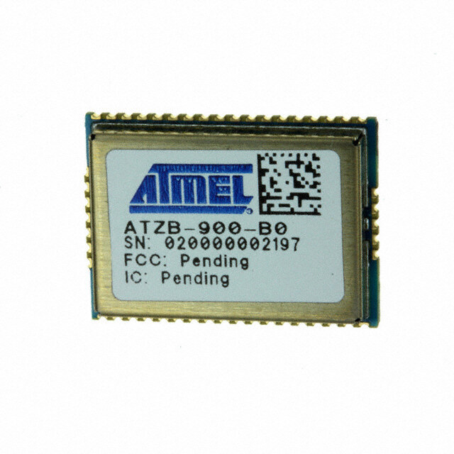
ICGOO电子元器件商城为您提供ZICM357SP2-1C由CEL设计生产,在icgoo商城现货销售,并且可以通过原厂、代理商等渠道进行代购。 ZICM357SP2-1C价格参考。CELZICM357SP2-1C封装/规格:RF 收发器模块, 。您可以下载ZICM357SP2-1C参考资料、Datasheet数据手册功能说明书,资料中有ZICM357SP2-1C 详细功能的应用电路图电压和使用方法及教程。
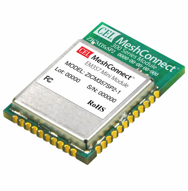
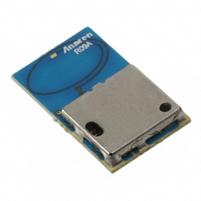
CEL的ZICM357SP2-1C是一款RF(射频)收发器模块,主要应用于无线通信系统中。该模块支持多频段操作,具备高性能和高集成度,适用于多种无线通信标准和协议。

其主要应用场景包括:

1. 无线局域网(WLAN)设备:用于Wi-Fi接入点、路由器和网关等设备中,实现高速无线数据传输。
2. 工业通信系统:在工业自动化与控制系统中,用于实现设备之间的无线数据交换,提升系统灵活性与部署便利性。
3. 物联网(IoT)设备:适用于智能家居、智能城市及远程监控等物联网应用,提供稳定可靠的无线连接。
4. 车载通信系统:用于车载信息娱乐系统、车载网络及远程信息处理设备中,支持车辆与外部网络的高效通信。
5. 测试与测量设备:在射频测试仪器中作为收发模块使用,用于通信设备的研发与维护。

该模块具备良好的射频性能和稳定性,适合对通信质量要求较高的应用场景。
| 参数 | 数值 |
| 产品目录 | |
| 描述 | RF TXRX EM357 MINI MODULE |
| 产品分类 | RF 收发器 |
| 品牌 | CEL |
| 数据手册 | |
| 产品图片 |
|
| 产品型号 | ZICM357SP2-1C |
| PCN设计/规格 | |
| rohs | 无铅 / 符合限制有害物质指令(RoHS)规范要求 |
| 产品系列 | MeshConnect™ |
| 其它名称 | ZICM357SP21C |
| 功率-输出 | 20dBm |
| 包装 | 托盘 |
| 天线连接器 | - |
| 存储容量 | 192kB 闪存,12kB RAM |
| 封装/外壳 | 模块 |
| 工作温度 | -40°C ~ 85°C |
| 应用 | 通用 |
| 数据接口 | PCB,表面贴装 |
| 数据速率(最大值) | 250kbps |
| 标准包装 | 330 |
| 灵敏度 | -103dBm |
| 电压-电源 | 2.1 V ~ 3.6 V |
| 电流-传输 | 150mA |
| 电流-接收 | 34mA |
| 调制或协议 | 802.15.4 Zigbee |
| 频率 | 2.4GHz |


- 商务部:美国ITC正式对集成电路等产品启动337调查
- 曝三星4nm工艺存在良率问题 高通将骁龙8 Gen1或转产台积电
- 太阳诱电将投资9.5亿元在常州建新厂生产MLCC 预计2023年完工
- 英特尔发布欧洲新工厂建设计划 深化IDM 2.0 战略
- 台积电先进制程称霸业界 有大客户加持明年业绩稳了
- 达到5530亿美元!SIA预计今年全球半导体销售额将创下新高
- 英特尔拟将自动驾驶子公司Mobileye上市 估值或超500亿美元
- 三星加码芯片和SET,合并消费电子和移动部门,撤换高东真等 CEO
- 三星电子宣布重大人事变动 还合并消费电子和移动部门
- 海关总署:前11个月进口集成电路产品价值2.52万亿元 增长14.8%


PDF Datasheet 数据手册内容提取
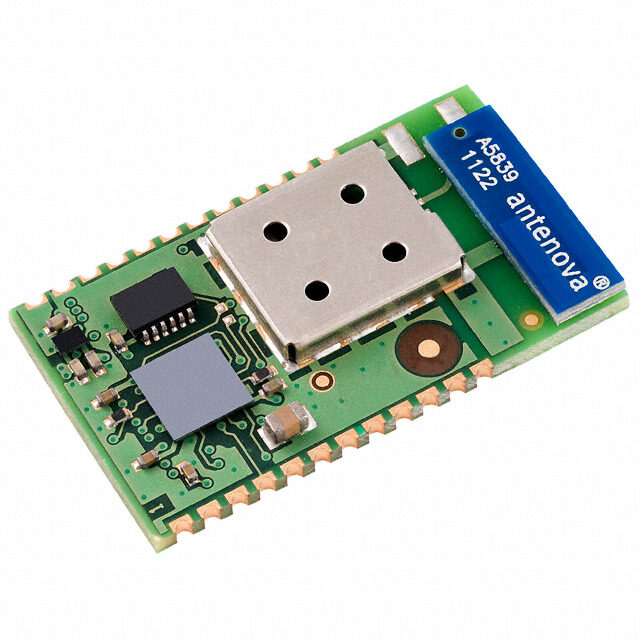
MeshConnect™ EM35x Mini Modules ZICM35xSP0 and ZICM35xSP2 EmberTM EM35x Transceiver-Based Modules Integrated Transceiver Modules for ZigBee®/Thread/IEEE 802.15.4 Development Kit Available: ZICM-EM35X-DEV-KIT-3 DESCRIPTION EM35x Mini Modules The MeshConnect™ EM35x Mini Modules from California Eastern Laboratories (CEL) combine high Powered by Ember® ZigBee® & Thread Solutions performance RF solutions with the market's premier KEY FEATURES: EM357 ZigBee® and Thread stacks. Available in low and • 32-bit ARM® Cortex™-M3 •• 11292kBkB S FRlAasMh high output power options (+8dBm and +20dBm), • Up to 23 GPIO Pins or these modules can accommodate variable range • SPI (Master/Slave), EM358x and performance requirements. The tiny module TWI and UART • Up to 64kB SRAM footprint makes them suitable for a wide range of • Timers and Serial • Up to 512kB Flash (Supports OTA) ZigBee and Thread applications. The MeshConnect Wire/JTAG Interface • Optional USB EM35x Mini Modules are certified and qualified, • 5-Channel 14-bit ADC Controller enabling customers to accelerate time to market by ZICM35xSP0 ZICM35xSP2 greatly reducing the design and certification phases Tx: +8dBm +20dBm of development. Rx: -100dBm -103dBm Link Budget: +108dB +123dB CEL’s MeshConnect EM35x Mini Modules ADDITIONAL FEATURES (ZICM35xSP0 and ZICM35xSP2) are based on the Ember EM35x (EM357 and EM358x) System on Chip • Data Rate: 250kbps • Antenna Options: • Advanced Power Management 1) Integrated PCB Trace Antenna (SoC) radio ICs. Each IC is a complete single-chip 2) RF Port for External Antenna • 16 RF Channels solution, compliant with ZigBee, Thread, and IEEE • Industry's Premier Wireless • Supports Mesh Networks 802.15.4. specifications. Networking Stacks: EmbeZNet • AES Encryption PRO™ (ZigBee) and Silicon Labs Thread • FCC, CE and IC Certifications CEL’s EM358x-based Mini Modules (ZICM358xSP0 • Mini Footprint: • RoHS Compliant and ZICM358xSP2) are ideal for customers requiring - 0.940" x 0.655" (23.9mm x 16.6mm) Over-the-Air (OTA) programming without an external Flash memory (such as Smart Energy or Home APPLICATIONS Automation), a larger memory footprint for complex • Smart Energy/Grid Markets • Commercial and Residential application control, or the additional resources to run - Thermostats Lighting - In-Home Displays - Fixtures and Control an IPv6-based networking stack like Thread. They - Smart Plugs • Solar Inverters and Control also feature an optional on-board Universal Serial • Home Automation and Control • General ZigBee and Thread Bus (USB) 2.0 full-speed peripheral. - Energy Management Wireless Sensor Networking - Security Devices - HVAC Control • Building Automation and Control This document is subject to change without notice Document No: 0011-00-07-01-000 (Issue H) Contributor Member Date Published: October 11, 2016 Page 1
EM35x Mini Modules TABLE OF CONTENTS Introduction and Overview Description.............................................................................................................................................................................................. 1 Features................................................................................................................................................................................................... 1 Applications............................................................................................................................................................................................ 1 Ordering Information.............................................................................................................................................................................. 3 ZICM35xSPx Product Comparison Table.............................................................................................................................................. 4 Module Block Diagram........................................................................................................................................................................... 4 Development Tools.................................................................................................................................................................................. 5 System Level Function Transceiver IC.......................................................................................................................................................................................... 6 Antenna.................................................................................................................................................................................................... 6 Power Amplifier....................................................................................................................................................................................... 6 USB........................................................................................................................................................................................................... 7 Software/Firmware................................................................................................................................................................................. 7 Electrical Specification Absolute Maximum Ratings................................................................................................................................................................... 8 Recommended Operating Condition..................................................................................................................................................... 8 DC Characteristics.................................................................................................................................................................................. 8 RF Characteristics.................................................................................................................................................................................. 9 Pin Signal and Interfaces Pin Signals I/O Configuration............................................................................................................................................................... 10 I/O Pin Assignment................................................................................................................................................................................ 10 Module Dimensions................................................................................................................................................................................ 11 Module Land Footprint........................................................................................................................................................................... 12 Processing.......................................................................................................................................................................................... 13 Agency Certifications.................................................................................................................................................................... 15 Software Compliance.................................................................................................................................................................... 16 Shipment, Storage and Handling............................................................................................................................................. 18 Quality................................................................................................................................................................................................... 18 References.......................................................................................................................................................................................... 19 Revision History............................................................................................................................................................................... 19 This document is subject to change without notice Document No: 0011-00-07-01-000 (Issue H) Page 2 Contributor Member
EM35x Mini Modules ORDERING INFORMATION Min/ Part Number Order Number Description Multiple ZICM357SP0-1-R EM357 IC, +8dBm output power, PCB trace antenna; Tape and Reel Package 600/600 ZICM357SP0-1C-R EM357 IC, +8dBm output power with castellation pin for external antenna; Tape and Reel Package 600/600 ZICM357SP2-1-R * EM357 IC, +20dBm output power, PCB trace antenna; Tape and Reel Package 600/600 ZICM357SP2-1C-R * EM357 IC, +20dBm output power with castellation pin for external antenna; Tape and Reel Package 600/600 ZICM357SP2-2-R EM357 IC, +20dBm output power, PCB trace antenna; Tape and Reel Package 600/600 MeshConnect ZICM357SP2-2C-R EM357 IC, +20dBm output power with castellation pin for external antenna; Tape and Reel Package 600/600 EM35x Mini Modules ZICM3588SP0-1-R EM3588 IC, +8dBm output power, PCB trace antenna; Tape and Reel Package 600/600 ZICM3588SP0-1C-R EM3588 IC, +8dBm output power with castellation pin for external antenna; Tape and Reel Package 600/600 ZICM3588SP2-1-R * EM3588 IC, +20dBm output power, PCB trace antenna; Tape and Reel Package 600/600 ZICM3588SP2-1C-R * EM3588 IC, +20dBm output power with castellation pin for external antenna; Tape and Reel Package 600/600 ZICM3588SP2-2-R * EM3588 IC, +20dBm output power, PCB trace antenna; Tape and Reel Package 600/600 ZICM3588SP2-2C-R * EM3588 IC, +20dBm output power with castellation pin for external antenna; Tape and Reel Package 600/600 MeshConnect EM35x Development Kit ZICM-EM35X-DEV-KIT-3 MeshConnect EM35x Ember Companion Kit for Ember EM35x Development Kit 1/1 *Note: ZICM35xSP2-1(C) modules are not recommended for new designs, although there are no plans to stop production. Use ZICM35xSP2-2(C) instead. The -2 part numbers allow for faster 'time to sleep' state at the expense of one less GPIO (PC6). This document is subject to change without notice Document No: 0011-00-07-01-000 (Issue H) Page 3 Contributor Member
EM35x Mini Modules ZICM35xSPx PRODUCT COMPARISON TABLE MCU Performance Tx Sleep / Rx Rx Tx Order Number Flash SRAM Power Sensitivity Current Current Suspend Comments USB I/O Output Current Memory Memory dBm dBm mA mA µA ZICM357SP0-1 23 +8 -100 30 44 ZICM357SP0-1C ZICM357SP2-1 192 kB 12 kB – 22 1 ZICM357SP2-1C +20 -103 34 150 ZICM357SP2-2 Reduced GPIO allows for 21 ZICM357SP2-2C faster 'time to sleep' state ZICM3588SP0-1 2.4 µA with entire RAM 23 +8 -100 30 44 ZICM3588SP0-1C retained. Lower sleep ZICM3588SP2-1 current can be achieved ZICM3588SP2-1C 22 by retaining less RAM 1) 2.4 µA with entire RAM 512 kB 64 kB ü 2.4 retained. Lower sleep current can be achieved +20 -103 34 150 ZICM3588SP2-2 by retaining less RAM ZICM3588SP2-2C 21 2) Reduced GPIO allows for faster 'time to sleep' state MODULE BLOCK DIAGRAMS EM35x Mini Module (ZICM35xSP0) 24MHz XTAL or Ember EM35x nct oe atinn astelle Co Micro Radio Balun LPF Cg d E EM35x Mini Module (ZICM35xSP2) 24MHz XTAL or Ember EM35x nct oe astellatie Conn Micro Radio PALNA TSXw/iRtcXh LPF Cg d E This document is subject to change without notice Document No: 0011-00-07-01-000 (Issue H) Page 4 Contributor Member
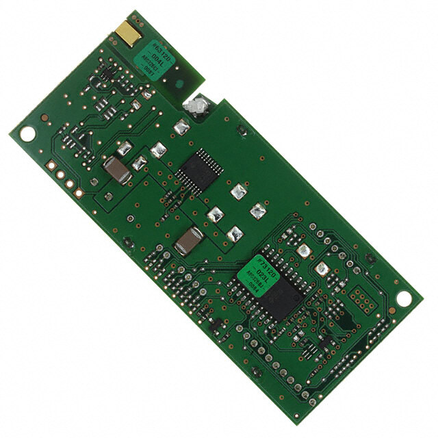
EM35x Mini Modules DEVELOPMENT TOOLS EM35x Ember Companion Kit Ember Companion Kit CEL’s MeshConnect EM35x Ember Companion Kit is Kit Contents: designed to work with the Silicon Laboratories/ Ember • ZICM357SP0-1C-SL Development Kits (EM35X-DEV and EM35X-DEV-IAR). • ZICM357SP2-1-SL Each module in the CEL Development Kit is soldered on • ZICM357SP2-1C-SL a carrier board making it pin-for-pin compatible with the • ZICM3588SP0-1C-SL Ember Development Board. • ZICM3588SP2-1-SL • ZICM3588SP2-1C-SL Mini Modules Programming Fixture CEL's MeshConnect EM35x Mini Modules Programming EM35x Programming Fixture Fixture is a programming assembly designed to be used with the CEL ZICM35xSPx MeshConnect Mini Modules. It is useful for production programming or during application development when multiple firmware images are required to be loaded into a CEL Mini Module for testing and debugging. The programming assembly must be used in conjunction with an Ember Debug/InSight Adapter (ISA3) from Silicon Labs. For more information regarding the MeshConnect Development Tools, refer to the respective documents, or visit www.cel.com/MeshConnect. DEVELOPMENT TOOLS ORDERING INFORMATION Part Number Order Number Description MeshConnect MeshConnect EM35x Ember Companion Kit for Silicon Laboratories/ ZICM-EM35X-DEV-KIT-3 EM35x Ember Companion Kit Ember EM35x Development Kit MeshConnect ZICM35xSPx-PF-1 MeshConnect EM35x Mini Modules (ZICM35xSPx) Programming Fixture EM35x Programming Fixture This document is subject to change without notice Document No: 0011-00-07-01-000 (Issue H) Page 5 Contributor Member
EM35x Mini Modules TRANSCEIVER IC CEL’s MeshConnect EM35x Mini Modules use the Ember EM35x transceiver (EM357 or EM358x) IC. The IC incorporates a RF transceiver with baseband modem, a hardwired MAC and an embedded ARM® Cortex™-M3 microcontroller, offering an excellent low cost, high performance solution for all IEEE 802.15.4/ZigBee/Thread applications. For more information about the EM35x IC, visit www.silabs.com. ANTENNA CEL’s MeshConnect EM35x Mini Modules include an integrated Printed Circuit Board (PCB) trace antenna. An optional configuration which uses a castellation pin on the module allows the user to connect an external antenna. The ZICM35xSP0 has been certified with the PCB trace antenna and two external antennas (E-2820- CA, LSR 001-0100). The ZICM35xSP2 has been certified with the PCB trace antenna and a Nearson half-wave dipole antenna (part number: S181AH-2450S) on a 4 inch cable using the castellation pin of the module. Please refer to the document Mini Module External Antenna Implementation for details describing the requirements that must be followed to take advantage of the CEL certification. See Ordering Information on Page 3. The PCB antenna employs a topology that is compact and highly efficient. To maximize range, an adequate ground plane must be provided on the host PCB. Correctly positioned, the ground plane on the host PCB will contribute significantly to the antenna performance (it should not be directly under the module PCB Antenna). The position of the module on the host board and overall design of the product enclosure contribute to antenna performance. Poor design affects radiation patterns and can result in reflection, diffraction and/or scattering of the transmitted signal. For optimum antenna performance, the MeshConnect Modules should be mounted with the PCB trace antenna overhanging the edge of the host board. To further improve performance, a ground plane may be placed on the host board under the module, up to the antenna (a minimum of 1.5" x 1.5" is recommended). The installation of an uninterrupted ground plane on a layer directly beneath the module will also allow you to run traces under this layer. CEL can provide assistance with your PCB layout. The following are some design guidelines to help ensure antenna performance: • Never place the ground plane or route copper traces directly underneath the antenna portion of the module • Never place the antenna close to metallic objects • In the overall design, ensure that wiring and other components are not placed near the antenna • Do not place the antenna in a metallic or metalized plastic enclosure • Keep plastic enclosures 1cm or more away from the antenna in any direction This radio transmitter IC: 8254A-ZICM357SP0 & IC: 8254A-ZICM357SP2 has been approved by IC Canada to operate with the antenna types listed above with the maximum permissible gain of 2dBi. Antenna types not included in this list, having a gain greater than the maximum gain indicated for that type, are strictly prohibited for use with this device. Cet émetteur radio IC: 8254A-ZICM357SP0 & IC: 8254A-ZICM357SP2 a été approuvé par IC Canada pour fonctionner avec les types d'antenne énumérés ci-dessus avec le gain maximal admissible de 2dBi. Types d'antennes non inclus dans cette liste, ayant un gain supérieur au gain maximum indiqué pour ce type, sont strictement interdits pour une utilisation avec cet appareil. POWER AMPLIFIER CEL’s MeshConnect EM35x High Power Mini Module (ZICM35xSP2) includes a Power Amplifier (PA). This PA delivers high efficiency, high gain and high output power (Pout = +20.0dBm typical) to provide an extended range and reliable transmission for fewer nodes in a network. For the ZICM35xSP2, Power Mode 2 with Power Setting -2 is the maximum setting allowed for FCC Compliance. Operating in Power Mode 3 at higher power settings may damage the PA. This document is subject to change without notice Document No: 0011-00-07-01-000 (Issue H) Page 6 Contributor Member
EM35x Mini Modules USB The ZICM3588SPx-x Modules have an integrated USB 2.0-compliant, full-speed (12Mbps) device peripheral. For more information, refer to the EM35x SoC Datasheet link provided in the References Section of this document. SOFTWARE/FIRMWARE CEL’s MeshConnect EM35x Mini Modules are ideal platforms for EmberZNet PRO, the industry’s most deployed and field proven ZigBee compliant stack supporting the ZigBee PRO feature set. EmberZNet PRO is a complete ZigBee protocol software package containing all the elements required for mesh networking applications. The ZICM3588SPx variants are also ideal platforms for Thread, an IP-based mesh networking stack that allows direct IPv6 connectivity to all devices within the network. For more information regarding the software development for the EM35x IC family, visit www.silabs.com. CEL provides reference software that runs multiple functions and executes various commands. For example, users can set up a simple ZigBee network to perform Range and Packet Error Rate (PER) tests between two devices. This allows the user to evaluate the module's RF performance in their own environment. The software can also place the module in various operating modes which allows for testing of low-level RF performance, GPIO functionality, etc. The ZICM35xSP0 Module uses the transceiver's primary RF ports for transmitting and should use Power Mode 1 (EMBER_TX_POWER_MODE_BOOST in the EmberZNet API). The ZICM35xSP2 Module uses the transceiver's alternate RF ports for transmitting and should use Power Mode 2 (EMBER_TX_POWER_MODE_ALTERNATE in the EmberZNet API). GPIO PC5 must also be configured as ALT_OUT (push/pull). This document is subject to change without notice Document No: 0011-00-07-01-000 (Issue H) Page 7 Contributor Member
EM35x Mini Modules ABSOLUTE MAXIMUM RATINGS MeshConnect ZICM35xSPx Module Description Unit Min Max Power Supply Voltage (VDD) -0.3 3.6 VDC Voltage on any I/O Line -0.3 VDD + 0.3 VDC ZICM35xSP0 – +15 RF Input Power dBm ZICM35xSP2 – +5 Storage Temperature Range -40 125 °C Reflow Soldering Temperature – 260 °C Note: Exceeding the maximum ratings may cause permanent damage to the module or devices. RECOMMENDED OPERATING CONDITIONS MeshConnect ZICM35xSPx Module Description Unit Min Typ Max Power Supply Voltage (VDD) 2.1 3.3 3.6 VDC Input Frequency 2405 – 2480 MHz Ambient Temperature Range -40 25 85 °C DC CHARACTERISTICS (@ 25°C, VDD = 3.3V, ZICM35xSP0 TX Power Mode 1, ZICM35xSP2 TX Power Mode 2) MeshConnect ZICM35xSPx Module Description Unit Min Typ Max Transmit Mode Current @ +8dBm – 44 – mA Transmit Mode Current @ 0dBm ZICM35xSP0 – 31 – mA Receive Mode Current – 30 – mA Transmit Mode Current @ +20dBm – 150 – mA Transmit Mode Current @ 0dBm ZICM35xSP2 – 58 – mA Receive Mode Current – 34 – mA Sleep Mode Current ZICM357SPx – 1 – µA Sleep Mode Current ZICM358xSPx – 2.4* – µA *Note: The increased sleep current on the ZICM358xSPx is at 3.6VDC with all the RAM retained. Lower sleep currents can be achieved if less RAM is retained during sleep. This document is subject to change without notice Document No: 0011-00-07-01-000 (Issue H) Page 8 Contributor Member
EM35x Mini Modules RF CHARACTERISTICS (@ 25°C, VDD = 3.3V, ZICM35xSP0 TX Power Mode 1, ZICM35xSP2 TX Power Mode 2) MeshConnect ZICM35xSPx Module Description Unit Min Typ Max General Characteristics RF Frequency Range 2405 – 2480 MHz RF Channels 11 – 26 – Frequency Error Tolerance -96.2 – 96.2 kHz Transmitter Maximum Output Power – +8 – dBm Minimum Output Power ZICM35xSP0 – -40 – dBm Offset Error Vector Magnitude – 5 35 % Maximum Output Power – +20 21 dBm (using Power Mode 2, Power Setting -2) ZICM35xSP2 Minimum Output Power – -40 – dBm Offset Error Vector Magnitude – 5 35 % Receiver Sensitivity (1% PER, Boost Mode) – -100 -94 dBm ZICM35xSP0 Saturation (Maximum Input Level) 0 – – dBm Sensitivity (1% PER, Normal Mode) – -103 -97 dBm ZICM35xSP2 Saturation (Maximum Input Level) -10 – – dBm Note: The ZICM35xSP2, Power Mode 2 with Power Setting -2 is the maximum setting allowed for FCC Compliance. Operating in Power Mode 3 at higher power settings may damage the PA. This document is subject to change without notice Document No: 0011-00-07-01-000 (Issue H) Page 9 Contributor Member
EM35x Mini Modules PIN SIGNALS I/O PORT CONFIGURATION CEL’s MeshConnect Module has 33 edge I/O interfaces for connection to the user’s host board. See the MeshConnect Module Dimensions Section which details the layout of the 33 edge castellations. I/O PIN ASSIGNMENTS CEL MeshConnect EM35x IC ZICM35xSPx Module Name Notes Pin Number Pin Number 1, 2, 12, 31, 33 49 GROUND ZICM35xSP0: Digital I/O ZICM35xSP2: Dedicated as TX_ACTIVE. The EM35x baseband 3 11 PC5 controls TX_ACTIVE and drives it high when in TX mode; since it is used internally in the module, PC5 is not connected to module I/O pin 3 4 12 RESET Active Low chip reset (Input) ZICM35xSP0: Digital I/O ZICM35xSP2-1: Digital I/O 5 13 PC6 ZICM35xSP2-2: Used internally in the module; PC6 is not connected to module I/O pin 5 6 14 PC7 Digital I/O 7 18 PA7 Digital I/O 8 19 PB3 Digital I/O 9 20 PB4 Digital I/O 10 21 PA0 Digital I/O 11 22 PA1 Digital I/O 13 16, 23, 28, 37 VDD 14 24 PA2 Digital I/O 15 25 PA3 Digital I/O 16 26 PA4 Digital I/O 17 27 PA5 Digital I/O 18 29 PA6 Digital I/O 19 30 PB1 Digital I/O 20 31 PB2 Digital I/O 21 32 JTCK JTAG clock input from debugger 22 33 PC2 Digital I/O 23 34 PC3 Digital I/O 24 35 PC4 Digital I/O 25 36 PB0 Digital I/O 26 38 PC1 Digital I/O 27 40 PC0 Digital I/O 28 41 PB7 Digital I/O 29 42 PB6 Digital I/O 30 43 PB5 Digital I/O 32 NC RF Out Castellation Pin for external Antenna This document is subject to change without notice Document No: 0011-00-07-01-000 (Issue H) Page 10 Contributor Member
EM35x Mini Modules MODULE DIMENSIONS MeshConnect EM35x Mini Modules EM300 Series Module ZICM35xSPx0000-00-00-00-000 Pin 33 Pin 1 CC77 CC77BB RR1100CC2211 C20C20 RR1111 CC2233 CC1111 ) CC2222 m LLCC331133 CC2244CC55BB L5L5 RR88 m RR11 LL44 87 RRUU7711 CC1144LL22 CC66 LLCCCC666666AABB CC11 CC22 ” (23. 0 CC99 RR22 SS CCCC4411AA77 RR55 RR44 0.94 eeEE rierieMM CC1166 CC1100 ARMARM ss357357 RR66 RR99 XXTTAALL11 Pin 11 CC1155 Pin 22 0.062” (1.57mm) 0.655” (16.63mm) 0.152” (3.86mm) MAX Note: All dimensions are +/- 0.005" (0.12mm) unless otherwise specified. This document is subject to change without notice Document No: 0011-00-07-01-000 (Issue H) Page 11 Contributor Member
EM35x Mini Modules MODULE LAND FOOTPRINT Dimensions are shown in inches, with millimeter conversions in brackets. 0.655” [16.64] 0.465” [11.80] 0.221” [5.61] 0.236” [5.98] Ø0.140” [Ø3.56] 0.940” [23.88] 0.590” [14.98] 0.985” [25.02] PITCH 0.050” [1.27] 0.540” [13.73] 33X 0.090” [2.29] X 0.040” [1.02] 0.084” [2.13] 0.084” [2.13] 0.082” [2.09] 0.490” [12.45] 0.746” [18.95] Note: Refer to the Antenna Section in this document for layout recommendations which will yield optimal antenna performance. This document is subject to change without notice Document No: 0011-00-07-01-000 (Issue H) Page 12 Contributor Member
EM35x Mini Modules PROCESSING Recommended Reflow Profile Parameter Values Ramp Up Rate (from Tsoakmax to Tpeak) 3º/sec max Tsoakmin 150ºC Tsoakmax 200ºC Soak Time 60-120 sec TLiquidus 217ºC Time above TLiquidus 60-150 sec Tpeak 250ºC Time within 5º of Tpeak 20-30 sec Time from 25º to Tpeak 8 min max Ramp Down Rate 6ºC/sec max Pb-Free Solder Paste Use of “No Clean” soldering paste is strongly recommended, as it does not require cleaning after the soldering process. Note: The quality of solder joints on the castellations ("half vias") where they contact the host board should meet the appropriate IPC Specification. See the Castellated Terminations Section in the latest IPC-A-610 Acceptability of Electronic Assemblies document. Cleaning In general, cleaning the populated module is strongly discouraged. Residuals under the module cannot be easily removed with any cleaning process. • Cleaning with water can lead to capillary effects where water is absorbed into the gap between the host board and the module. The combination of soldering flux residuals and encapsulated water could lead to short circuits between neighboring pads. Water could also damage any stickers or labels. • Cleaning with alcohol or a similar organic solvent will likely flood soldering flux residuals into the two housings, which is not accessible for post-washing inspection. The solvent could also damage any stickers or labels. • Ultrasonic cleaning could damage the module permanently. The best approach is to consider using a “No Clean” solder paste and eliminate the post-soldering cleaning step. Optical Inspection After soldering the module to the host board, consider optical inspection to check the following: • Proper alignment and centering of the module over the pads • Proper solder joints on all pads • Excessive solder or contacts to neighboring pads or vias Repeating Reflow Soldering Only a single reflow soldering process is encouraged for host boards. Wave Soldering If a wave soldering process is required on the host boards due to the presence of leaded components, only a single wave soldering process is encouraged. Hand Soldering Hand soldering is possible. When using a soldering iron, follow IPC recommendations (reference document IPC-7711). This document is subject to change without notice Document No: 0011-00-07-01-000 (Issue H) Page 13 Contributor Member
EM35x Mini Modules Rework The MeshConnect Module can be unsoldered from the host board. Use of a hot air rework tool should be programmable and the solder joint and module should not exceed the maximum peak reflow temperature of 250ºC. Caution If temperature ramps exceed the reflow temperature profile, module and component damage may occur due to thermal shock. Avoid overheating. Warning Never attempt a rework on the module itself (i.e., replacing individual components); such actions will terminate warranty coverage. Additional Grounding Attempts to improve the module or the system grounding by soldering braids, wires or cables onto the module RF shield cover is done at the customer's own risk. The ground pins at the module perimeter should be sufficient for optimum immunity to external RF interference. This document is subject to change without notice Document No: 0011-00-07-01-000 (Issue H) Page 14 Contributor Member
EM35x Mini Modules AGENCY CERTIFICATIONS The following Part Numbers are Certified as shown below: Part Number Certifications Antenna ZICM35xSP0-1 FCC, IC, CE PCB ZICM35xSP0-1C FCC, IC, CE E-2820-CA, LSR 001-0100 ZICM35xSP2-x FCC, IC PCB ZICM35xSP2-xC FCC, IC Nearson S181AH-2450S FCC and Canada Compliance Statement This device complies with Part 15 of the FCC Rules and with IC Canada licence-exempt RSS Standards. Operation is subject to the following two conditions: 1. This device may not cause harmful interference, and 2. This device must accept any interference received, including interference that may cause undesired operation. Déclaration De Conformité FCC Et Au Canada Le présent appareil est conforme aux CNR d'Industrie Canada applicables aux appareils radio exempts de licence. L'exploitation est autorisée aux deux conditions suivantes: 1. l'appareil ne doit pas produire de brouillage, et 2. l'utilisateur de l'appareil doit accepter tout brouillage radioélectrique subi, même si le brouillage est susceptible d'en compromettre le fonctionnement. Warning (Part 15.21) Changes or modifications not expressly approved by CEL could void the user's authority to operate the equipment. 20cm Separation Distance To comply with FCC/IC Canada RF exposure limits for general population/uncontrolled exposure, the antenna(s) used for this transmitter must be installed to provide a separation distance of at least 20cm from all persons and must not be co-located or operated in conjunction with any other antenna or transmitter except in accordance with FCC muti-transmitter product procedures. 20cm Distance De Séparation Pour se conformer aux limites d'exposition FCC / IC Canada RF pour la population générale / exposition non contrôlée, l'antenne(s) utilisée pour ce transmetteur doit être installé pour fournir une distance de séparation d'au moins 20cm de toutes les personnes et ne doit pas être co-implantés ou exploités en conjonction avec une autre antenne ou émetteur, sauf en conformité avec les procédures de produits muti-émetteur FCC. OEM Responsibility to the FCC and IC Rules and Regulations The MeshConnect Mini Module has been certified per FCC Part 15 Rules and to IC Canada license-exempt RSS Standards for integration into products without further testing or certification. To fulfill the FCC and IC Certification requirements, the OEM of the MeshConnect Module must ensure that the information provided on the MeshConnect label is placed on the outside of the final product. The MeshConnect Mini Module is labeled with its own FCC ID Number and IC ID Number. If the FCC ID and the IC ID are not visible when the module is installed inside another device, then the outside of the device into which the module is installed must also display a label referring to the enclosed module. The exterior label can use wording such as the following: This document is subject to change without notice Document No: 0011-00-07-01-000 (Issue H) Page 15 Contributor Member
EM35x Mini Modules “Contains Transmitter Module FCC ID: W7Z-ZICM357SP0” or “Contains FCC ID: W7Z-ZICM357SP0” “Contains Transmitter Module IC: 8254A-ZICM357SP0" or "Contains IC: 8254A-ZICM357SP0” or “Contains Transmitter Module FCC ID: W7Z-ZICM357SP2” or “Contains FCC ID: W7Z-ZICM357SP2” “Contains Transmitter Module IC: 8254A-ZICM357SP2" or "Contains IC: 8254A-ZICM357SP2” The OEM of the MeshConnect Mini Module may only use the approved antennas (PCB Trace Antenna and external antenna) that have been certified with this module. The OEM of the MeshConnect Mini Module must test their final product configuration to comply with Unintentional Radiator Limits before declaring FCC Compliance per Part 15 of the FCC Rules. The OEM must also include in their manual the following statement: FCC and Canada Compliance Statement This device complies with Part 15 of the FCC Rules and with IC Canada licence-exempt RSS Standards. Operation is subject to the following two conditions: 1. This device may not cause harmful interference, and 2. This device must accept any interference received, including interference that may cause undesired operation. Déclaration De Conformité FCC Et Au Canada Le présent appareil est conforme aux CNR d'Industrie Canada applicables aux appareils radio exempts de licence. L'exploitation est autorisée aux deux conditions suivantes: 1. l'appareil ne doit pas produire de brouillage, et 2. l'utilisateur de l'appareil doit accepter tout brouillage radioélectrique subi, même si le brouillage est susceptible d'en compromettre le fonctionnement. In addition to using only the approved external antennas, the OEM must follow the layout described in the "Mini Module External Antenna Implementation Guide" to be covered by the current approval. CE Certification — Europe The MeshConnect ZICM35xSP0 Module has been tested and certified for use in the European Union. OEM Responsibility to the European Union Compliance Rules If the MeshConnect Module is to be incorporated into a product, the OEM must verify compliance of the final product to the European Harmonized EMC and Low-Voltage/Safety Standards. A Declaration of Conformity must be issued for each of these standards and kept on file as described in Annex II of the R&TTE Directive. The manufacturer must maintain the user guide and adhere to the settings described in the manual for maintaining European Union Compliance. If any of the specifications are exceeded in the final product, the OEM is required to make a submission to the notified body for compliance testing. This document is subject to change without notice Document No: 0011-00-07-01-000 (Issue H) Page 16 Contributor Member
EM35x Mini Modules OEM Labeling Requirements The CE mark must be placed on the OEM product in a visible location. The CE mark shall consist of the initials CE with the following form: · If the CE marking is reduced or enlarged, the proportions given in the CE graduated drawing (to the right) must be adhered to · The CE mark must be a minimum of 5mm in height · If the use of the module is subject to restrictions in the end application, the CE marking on the OEM product should also include the alert sign as shown in the image to the right Software Compliance The MeshConnect Mini Modules require software restrictions to meet agency certification requirements. These restrictions have been implemented in the sample application included with the Software Development Kit. If a customer is not starting with the CEL Software Development Kit, they must implement the following output power restrictions to use the FCC, IC or CE Certifications: Valid TX Typical Max Part Number Certification RF Channel Power Steps Output Power 11 - 25 -43 to 8 8dBm FCC/IC ZICM35xSP0-1 26 -43 to 0 1dBm ETSI 11 - 26 -43 to 8 8dBm 11 - 25 -43 to 8 8dBm FCC/IC ZICM35xSP0-1C 26 -43 to -7 -7dBm ETSI 11 - 26 -43 to 8 8dBm 11 - 24 -43 to -2 20dBm ZICM35xSP2-x FCC/IC 25 -43 to -6 17dBm 26 -43 to -21 -5dBm 11 - 24 -43 to -2 20dBm ZICM35xSP2-xC FCC/IC 25 -43 to -12 9dBm 26 -43 to -21 -5dBm Note: The ZICM35xSP2, Power Mode 2 with Power Setting -2 is the maximum setting allowed for FCC Compliance. Operating in Power Mode 3 at higher power settings may damage the PA. This document is subject to change without notice Document No: 0011-00-07-01-000 (Issue H) Page 17 Contributor Member
EM35x Mini Modules SHIPMENT, HANDLING AND STORAGE Shipment The MeshConnect Modules are delivered in Tape and Reel for easy assembly in a manufacturing environment. The reel diameter is 12.992 inches (330mm) and contains 600 modules Tape and Reel Dimensions Measurements are in inches [mm] Handling The MeshConnect Modules are designed and packaged to be processed in an automated assembly line. 0.079±0.004 [2.00±0.10] 0.157 [4.00] PITCH 0.071±0.004 [1.75±0.10] A 0.957±0.004 [24.30±0.10] B B 0.795±0.006 [20.20±0.15] 1.732±0.011 [44.00±0.30] 0.014±0.002 [0.35±0.05] A 0.945±0.004 [24.00±0.10] 0.169±0.004 [4.30±0.10] 0.669±0.004 [17.00±0.10] SECTION A-A SECTION B-B Warning The MeshConnect Modules contain highly sensitive electronic circuitry. Handling without proper ESD protection may destroy or damage the module permanently. Warning The MeshConnect Modules are moisture-sensitive devices. Appropriate handling instructions and precautions are summarized in J-STD-033. Read carefully to prevent permanent damage due to moisture intake. Moisture Sensitivity Level (MSL) MSL 3, per J-STD-033 Storage Storage/shelf life in sealed bags is 12 months at <40°C and <90% relative humidity. QUALITY CEL Modules offer the highest quality at competitive prices. Our modules are manufactured in compliance with the IPC-A-610 specification, Class II. Our modules go through JESD22 qualification processes which include high temperature operating life tests, mechanical shock, temperature cycling, humidity and reflow testing. CEL conducts RF and DC factory testing on 100% of all production parts. CEL builds the quality into our products, giving our customers confidence when integrating our products into their systems. This document is subject to change without notice Document No: 0011-00-07-01-000 (Issue H) Page 18 Contributor Member
EM35x Mini Modules REFERENCES Reference Documents Download 120-035X-000 - Silicon Labs/Ember EM35x SoC Datasheet Link 0011-02-17-00-000 - CEL EM35x Ember Mini Module Companion Kit Technical User Guide Link 0011-01-16-05-000 - Using the ZICM35xSPx Mini Module Programming Fixture Link 0011-00-16-11-000 - CEL ZICM35xSP2-1C External Antenna Implementation Link REVISION HISTORY Previous Versions Changes to Current Version Page(s) 0011-00-07-01-000 Initial Preliminary Datasheet All (Issue A) July 22, 2013 0011-00-07-01-000 Updated Development Tools Section, Antenna Section, Agency Certifications, 4, 5, 14, 16, 17 (Issue B) August 1, 2013 Software Compliance Section 0011-00-07-01-000 Updated Tape and Reel Packaging 3, 17 (Issue C) February 10, 2014 0011-00-07-01-000 Updated ZICM358xSPx Sleep Mode Current. Removed "Preliminary" status for this 1, 7, 16 (Issue D) March 17, 2014 datasheet. Updated Software Compliance "Valid" TX Power Steps" table values This datasheet is now a "Preliminary Datasheet" due to the addition of new part numbers 0011-00-07-01-000 (ZICM357SP2-2, ZICM357SP2-2-R, ZICM357SP2-2C and ZICM357SP2-2C-R) to the 1, 3 (Issue E) March 18, 2014 "Ordering Information". Added new "ZICM35xSPx Product Comparison Table". 0011-00-07-01-000 Removed "Preliminary" status for this datasheet. Updated Programming Fixture 1, 5 (Issue F) July 15, 2014 Product Photography 0011-00-07-01-000 Added part numbers ZICM3588SP2-2(C), updated Logos 3 (Issue G) July 20, 2014 Changed "Industry Canada" to "IC Canada" throughout document. Updated Antenna 0011-00-07-01-000 Section and added a new part number to Agency Certifications table. 4,6,15,17,18 (Issue H) October 11, 2016 Added ZICM35xSP0-1C to Software compliance table. Removed option for tray configuration This document is subject to change without notice Document No: 0011-00-07-01-000 (Issue H) Page 19 Contributor Member
EM35x Mini Modules Disclaimer The information in this document is current as of the published date. The information is subject to change without notice. For actual design-in, refer to the latest publications of CEL Data Sheets or Data Books, etc., for the most up-to-date specifications of CEL products. Not all products and/or types are available in every country. Please check with an CEL sales representative for availability and additional information. No part of this document may be copied or reproduced in any form or by any means without the prior written consent of CEL. CEL assumes no responsibility for any errors that may appear in this document. CEL does not assume any liability for infringement of patents, copyrights or other intellectual property rights of third parties by or arising from the use of CEL products listed in this document or any other liability arising from the use of such products. No license, express, implied or otherwise, is granted under any patents, copyrights or other intellectual property rights of CEL or others. Descriptions of circuits, software and other related information in this document are provided for illustrative purposes in semiconductor product operation and application examples. The incorporation of these circuits, software and information in the design of a customer’s equipment shall be done under the full responsibility of the customer. CEL assumes no responsibility for any losses incurred by customers or third parties arising from the use of these circuits, software and information. While CEL endeavors to enhance the quality, reliability and safety of CEL products, customers agree and acknowledge that the possibility of defects thereof cannot be eliminated entirely. To minimize risks of damage to property or injury (including death) to persons arising from defects in CEL products, customers must incorporate sufficient safety measures in their design, such as redundancy, fire- containment and anti-failure features. For More Information For more information about CEL MeshConnect products and solutions, visit our website at: www.cel.com/MeshConnect. Technical Assistance For Technical Assistance, visit www.cel.com/MeshConnectHelp. This document is subject to change without notice Document No: 0011-00-07-01-000 (Issue H) Page 20 Contributor Member