
 Datasheet下载
- 型号: Y201132C203NQ
- 制造商: C&K Components
- 库位|库存: xxxx|xxxx
- 要求:
| 数量阶梯 | 香港交货 | 国内含税 |
| +xxxx | $xxxx | ¥xxxx |
查看当月历史价格
查看今年历史价格
Y201132C203NQ产品简介:
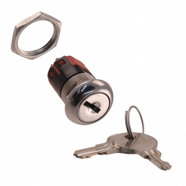
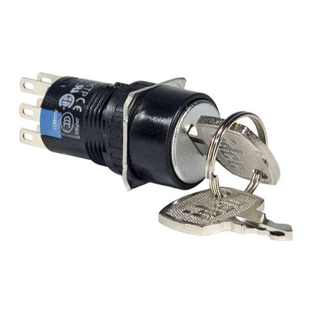
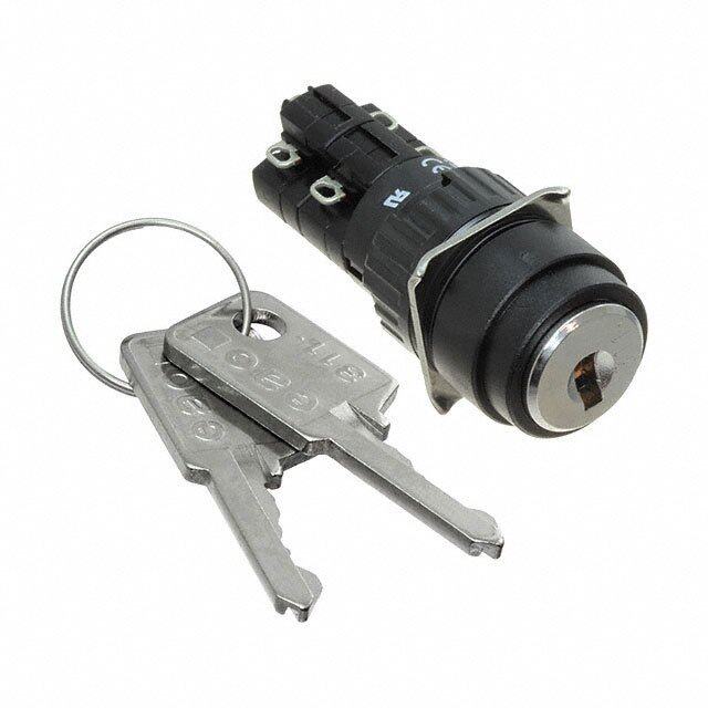
ICGOO电子元器件商城为您提供Y201132C203NQ由C&K Components设计生产,在icgoo商城现货销售,并且可以通过原厂、代理商等渠道进行代购。 Y201132C203NQ价格参考。C&K ComponentsY201132C203NQ封装/规格:键锁开关, Keylock Switch 2 Position DPDT 4A (AC/DC) 125VAC 28VDC Panel Mount。您可以下载Y201132C203NQ参考资料、Datasheet数据手册功能说明书,资料中有Y201132C203NQ 详细功能的应用电路图电压和使用方法及教程。
C&K品牌的Y201132C203NQ是一款键锁开关,属于高可靠性机械开关产品。该型号常用于需要安全锁定和权限控制的电子设备中。典型应用场景包括工业控制设备、医疗仪器、通信机柜、安防系统以及办公自动化设备等。其键锁设计可防止未经授权的操作,确保设备在特定条件下才能启动或设置更改,提升操作安全性与系统稳定性。Y201132C203NQ具备良好的耐用性和接触可靠性,适合在对开关寿命和性能要求较高的环境中使用。此外,该开关支持面板安装,结构紧凑,适用于空间有限的设备布局。由于C&K品牌在开关领域具有较高声誉,该型号也广泛应用于对品质有严格要求的中高端设备中。总体而言,Y201132C203NQ适用于需通过物理钥匙进行模式切换、电源控制或安全保护的场合,如设备维护模式切换、电源启停控制、参数调整锁定等,是保障设备安全运行的重要组件。
| 参数 | 数值 |
| 产品目录 | |
| 描述 | SWITCHLOCK DP 4A SOLDER LUG 125V键锁开关 Switchlocks 2P 2A |
| 产品分类 | |
| 品牌 | C&K Components |
| 产品手册 | |
| 产品图片 |
|
| rohs | 符合RoHS无铅 / 符合限制有害物质指令(RoHS)规范要求 |
| 产品系列 | 键锁开关,C&K Components Y201132C203NQY |
| mouser_ship_limit | 该产品可能需要其他文件才能进口到中国。 |
| 数据手册 | http://www.ck-components.com/index.php?module=media&action=Display&cmpref=13493&lang=en&width=&height=&format=&alt= |
| 产品型号 | Y201132C203NQ |
| 不同电压时的触头额定电流 | 4A @ 125VAC |
| 产品培训模块 | http://www.digikey.cn/PTM/IndividualPTM.page?site=cn&lang=zhs&ptm=30457 |
| 产品目录绘图 |
|
| 产品目录页面 | |
| 产品种类 | |
| 位置数量 | 1 |
| 其它名称 | *Y201132C203NQ |
| 变址 | 90 deg |
| 商标 | C&K Components |
| 外壳材料 | Polyester, Glass Filled |
| 安装类型 | 面板安装 |
| 工厂包装数量 | 1 |
| 抛射角 | 90° |
| 标准包装 | 1 |
| 电压额定值AC | 125 VAC |
| 电流额定值 | 2 A |
| 电路 | 双刀双掷 |
| 相关产品 | /product-detail/zh/937C00000/CKN10254-ND/2234017/product-detail/zh/175050700/CKN10075-ND/513037/product-detail/zh/115140126/CKC8028-ND/252693 |
| 端子类型 | 焊片 |
| 端接类型 | Solder Lug |
| 系列 | Y |
| 致动器类型 | 扁平按键 |
| 触点形式 | DPDT |
| 触点额定值 | 4 A |
| 针脚数 | 2 |
| 钥匙拔出位置 | 仅 1 |
| 键类型 | Switchlock |


- 商务部:美国ITC正式对集成电路等产品启动337调查
- 曝三星4nm工艺存在良率问题 高通将骁龙8 Gen1或转产台积电
- 太阳诱电将投资9.5亿元在常州建新厂生产MLCC 预计2023年完工
- 英特尔发布欧洲新工厂建设计划 深化IDM 2.0 战略
- 台积电先进制程称霸业界 有大客户加持明年业绩稳了
- 达到5530亿美元!SIA预计今年全球半导体销售额将创下新高
- 英特尔拟将自动驾驶子公司Mobileye上市 估值或超500亿美元
- 三星加码芯片和SET,合并消费电子和移动部门,撤换高东真等 CEO
- 三星电子宣布重大人事变动 还合并消费电子和移动部门
- 海关总署:前11个月进口集成电路产品价值2.52万亿元 增长14.8%


PDF Datasheet 数据手册内容提取
Y Series 4, 5 & 6 Tumbler Switchlocks Features/Benefits Typical Applications • Anti-static switch—exceeds • Point-of-sale terminals 20 KV DCstatic resistance • Cash registers • M omentary models available • Computers • W ire leads and harnesses available Patent No. 4,639,562 Models Available Specifications Materials CONTACT RATING: Q contact material: 4 AMPS @ 125 V AC or LOCK: Zinc alloy with stainless steel facing, std. (4 & 5 tumbler lock 28 V DC; 2 AMPS @ 250 V AC (UL/CSA). See page L-9 for and 6 tumbler tubular lock). additional ratings. KEYS: Two nickel plated brass keys, with code number, std. ELECTRICAL LIFE: 10,000 make-and-break cycles at full load. (4 and 5 tumbler lock). Two die cast chrome plated zinc alloy CONTACT RESISTANCE: Below 10 m Ω typ. initial @ 2-4 V DC, keys,std. (6 tumbler lock). 100 mA, for both silver and gold plated contacts. SWITCH HOUSING: Glass filled polyester (UL 94V-0). INSULATION RESISTANCE: 109 Ω min. CONTACTS AND TERMINALS: Q contact material: Copper, silver DIELECTRIC STRENGTH: 1,000 Vrms min. @ sea level. plated. See page L-9 for additional contact materials. INDEXING: 45º or 90º, 2-4 positions (4&5 tumbler switchlocks). MOUNTING NUT: Zinc alloy. 45º, 3 positions; or 90º, 2 positions (6 tumbler tubular switch- MOUNTING CLIP: Steel, zinc plated. locks). DRESS NUT: Brass, nickel plated. Other functions available, consult Customer Service Center. TERMINAL SEAL: Epoxy. STATIC RESISTANCE: Anti-static models exceed 20 KV DC static resistance @ sea level, lock body to terminals. NOTE: Any models supplied with Q, B or G contact material are RoHS compliant. MOUNTING TORQUE: 10 in./lbs.; 14 in./lbs max. NOTE: Specifications and materials listed above are for switchlocks with standard options. OPERATING TEMPERATURE: -30°C to 85°C. For information on specific and custom switchlocks, consult Customer Service Center. Build-A-Switch To order, simply select desired option from each category and place in the appropriate box. Available options are shown and described on pages L–4 through L–10. For additional options not shown in catalog, consult Customer Service Center. Switch and Lock Function Y10013 SP, 45°, keypull pos. 1 Keying Y1011U SP, 90°, keypull pos. 1 & 2 2 Two nickel plated brass keys (4 & Y1001U SP, 45°, keypull pos. 1 & 3 5 tumbler) or two die cast zinc alloy keys with Y2001U DP, 45°, keypull pos. 1 & 3 chrome plating (6 tumbler) Y10082 SP, 45°, keypull pos. 1 6 Two nickel plated brass keys with code on lock face Y20082 DP, 45°, keypull pos. 1 L Lock Type Y100AA SP, 45°, keypull pos. 1, 2 & 3 A 4 Tumbler lock (YXO8 models) Y200AA DP, 45°, keypull pos. 1, 2 & 3 C 4 Tumbler lock with detent S Y100AB SP, 45°, keypull pos. 1, 2, 3 & 4 V 6 Tumbler tubular lock w Y200AB DP, 45°, keypull pos. 1, 2, 3 & 4 B 5 Tumbler lock i Y10113 SP, 90°, keypull pos. 1 t R 4 Tumbler lock with detent and anti-Static switch c Y20113 DP, 90°, keypull pos. 1 W 6 Tumbler tubular lock with anti-Static switch h Y1011C SP, 90°, keypull pos.2 l Y2011C DP, 90°, keypull pos. 2 Lock Finish o Y2011U DP, 90°, keypull pos. 1 & 2 2 Stainless steel facing c Y14173 SP, 90°, keypull pos. 1 8 Gloss black facing Terminations Contact Material k Y1417U SP, 90°, keypull pos. 1,2 & 3 F Polished nickel facing 03 Solder lug with hole Q Silver Y10812 SP, 45°, mom., keypull pos. 1 01 Solder lug with notch B Gold Y20812 DP, 45°, mom., keypull pos. 1 02 PC Thru-hole G Gold over silver Y19073 SP w/common, 90°, keypull pos. 1 07 Solder lug with hole Y1907U SP w/common, 90°, keypull pos. 1, 2 & 3 (Y19OXX models only) Y1900S SP w/common, 90°, keypull pos. 1, 2, 3 & 4 WC Wire lead Seal NONE No seal Mounting/Lock Style E Epoxy seal N With nut D With clip L With removable dress nut and latch pawl R With removable dress nut Dimensions are shown: Inch (mm) Specifications and dimensions subject to change www.ckswitches.com L–3
Y Series 4, 5 & 6 Tumbler Switchlocks SWITCH AND LOCK FUNCTION SINGLE&DOUBLE POLESWITCHES CONNECTED TERMINALS NO. NO. MODEL POS. 1 POS. 2 POS. 3 POS. 4 KEYPULL LOCK TUMBLERS POLES NO. POSITIONS CONFIGURATION INDEXING POS. 1 2 4, 5 & 6 SP Y10013 8-1 1-2 2-3 Position 1 3 POS. 1 SP Y1001U 8-1 1-2 2-3 2 4, 5 & 6 Positions 1 & 3 DP Y2001U 8-1, 4-5 1-2, 5-6 2-3, 6-7 3 POS. 1 SP Y10082 8-1 1-2 7-8 3 2 4 & 5 Position 1 DP Y20082 8-1, 4-5 1-2, 5-6 7-8, 3-4 45º POS. 1 SP Y100AA 8-1 1-2 7-8 3 2 4 Positions 1, 2 & 3 DP Y200AA 8-1, 4-5 1-2, 5-6 7-8, 3-4 POS. 1 2 SP Y100AB 8-1 1-2 2-3 3-4 4 DP Y200AB 8-1, 4-5 1-2, 5-6 2-3, 6-7 3-4, 7-8 Positions 1, 2, 3 & 4 3 4 POS. 1 SP Y10113 8-1 1-3 4, 5 & 6 Position 1 DP Y20113 8-1, 4-5 1-3, 5-7 2 POS. 1 SP Y1011C 8-1 1-3 4 & 5 Position 2 DP Y2011C 8-1, 4-5 1-3, 5-7 2 POS. 1 SP Y1011U 8-1 1-3 4, 5 & 6 Positions 1 & 2 90º DP Y2011U 8-1, 4-5 1-3, 5-7 2 POS. 1 4 SP Y14173 7-1 1-3 6-7 Position 1 3 2 POS. 1 4 SP Y1417U 7-1 1-3 6-7 Positions 1, 2 & 3 3 2 SINGLE&DOUBLE POLEMOMENTARY SWITCHES L CONNECTED TERMINALS NO. NO. MODEL POS. 1 POS. 2 POS. 3 POS. 4 KEYPULL LOCK k TUMBLERS POLES NO. POSITIONS CONFIGURATION INDEXING c POS. 1 o 4 SP Y10812 8-1 1-2 Position 1 2 45º l DP Y20812 8-1, 4-5 1-2, 5-6 Mom. h c t i w S TERMINAL NUMBERS LEGEND Terminal numbers molded on bottom of housing. = Momentary Positions (45º) All models with all options when ordered = Detent Positions (45º or 90º) with ‘G’ or ‘Q’ contact material. = Key pull possible in these positions. = Stop Positions Dimensions are shown: Inch (mm) Specifications and dimensions subject to change www.ckswitches.com L–4
Y Series 4, 5 & 6 Tumbler Switchlocks SWITCH AND LOCK FUNCTION SINGLEPOLESWITCHES WITHCOMMON CONNECTED TERMINALS NO. NO. MODEL POS. 1 POS. 2 POS. 3 POS. 4 KEYPULL LOCK TUMBLERS POLES NO. POSITIONS CONFIGURATION INDEXING POS. 1 Y19073 Position 1 3 2 C-1 C-2 C-4 POS. 1 Y1907U Positions 1, 2 & 3 3 2 4 SP 90º POS. 1 4 2 Y1900S C-1 C-2 C-3 C-4 Positions 1, 2, 3 & 4 3 LEGEND TERMINAL NUMBERS Terminal numbers marked on insulator. = Detent Positions (45º or 90º) All models with all options when ordered = Key pull possible in these positions. with ‘G’ or ‘Q’ contact material. = Stop Positions NOTE: Epoxy seal not available. Removable dress nut not available with any Y190XX models. 4 & 5 Tumbler L SLOTS IN THIS LOCATION FOR MOUNTING STYLE 'D' CLIP S Part number shown: Y100132C203NQ w i 6 Tumbler t c h l o c k SLOTS IN THIS LOCATION FOR MOUNTING STYLE 'D' CLIP Part number shown: Y1011U2V203NQ Dimensions are shown: Inch (mm) Specifications and dimensions subject to change www.ckswitches.com L–5
Y Series 4, 5 & 6 Tumbler Switchlocks SWITCH AND LOCK FUNCTION AVAILABLE OPTION COMBINATIONS MOUNTING/LOCK LOCK TYPES TERMINATIONS STYLES MODELS A B C R V W 01 02 03 07 WC D L N R YX0013 • • • • • • • • • • • YX001U • • • • • • • • • • • • • YX0082 • • • • • • • • • YX00AX • • • • • • • • • YX0113 • • • • • • • • • • • • YX011C • • • • • • • • • • YX01IU • • • • • • • • • • • • • Y141XX • • • • • • • • • YX0812 • • • • • • • Y190XX • • • • • • • KEYING KEYING OPTION CODE NO. CODENO. CODE KEYINGOPTIONS ONKEY ONLOCK 2 NICKEL PLATED BRASS KEYS 2 (4 & 5 TUMBLER) or 2 DIE CAST CHROME YES NO PLATED ZINC ALLOY KEYS (6 TUMBLER) 6 2 NICKEL PLATED BRASS KEYS, 4 & 5 YES YES TUMBLER ONLY NOTE: All orders keyed alike, standard. For more than one key code, master keying, replacement keys, or other special features, consult Customer Service Center. L k c o NOTE: Keys are available separately, see page L-10. Key head shape subject to change without notice. l h c LOCK TYPE t i w C V A 4 TUMBLER LOCK WITH DETENT 6 TUMBLER TUBULAR LOCK 4 TUMBLER LOCK (MOMENTARY MODELS ONLY) S B 5 TUMBLER LOCK . Dimensions are shown: Inch (mm) Specifications and dimensions subject to change www.ckswitches.com L–6
Y Series 4, 5 & 6 Tumbler Switchlocks LOCK TYPE SHORT ANTI-STATIC LOCK TYPES R W 4 TUMBLER LOCK WITH DETENT AND 6 TUMBLER TUBULAR LOCK WITH SHORT ANTI-STATIC SWITCH. ANTI-STATIC SWITCH Available with Lock Finish '2' only. NOTE: For available option combinations, see page L-9. U.S. Pat. No. 4,639,562 Exceeds 20 KV DC static resistance @ sea level, lock body to terminals. LOCK FINISH 2 STAINLESS STEEL 8 GLOSS BLACK F POLISHED NICKEL Available with Lock Types ‘V’ & ‘W’ only. NOTE: For available option combinations, see page L-9. TERMINATIONS 03 01 02 WC SOLDER LUG WITH HOLE SOLDER LUG WITH NOTCH PC THRU-HOLE WIRE LEAD L Black wire standard. other colors S and lengths available, consult w Customer Service Center. All Models Except Y190 UL style 1015. it c 02 07 WC h PC THRU-HOLE SOLDER LUG WITH HOLE WIRE LEAD PC MOUNTING lo c k Black wire standard. other colors and lengths available, consult Y190 Model Only Customer Service Center. UL style 1015. Dimensions are shown: Inch (mm) Specifications and dimensions subject to change www.ckswitches.com L–7
Y Series 4, 5 & 6 Tumbler Switchlocks MOUNTING/LOCK STYLE N D .136 DIA. WITH NUT WITH CLIP (3,45) .105 PANEL MOUNTING (2,67) 3/4±24 UNS .470 (11,94) 1.000 .875 (25,40) (22,23) .225 .500 GRAIN (5,72) (12,70) DIRECTION BURR SIDE UP 1(2.051,605) (1.678,486) US PaT No5636540 .1(235,1 t8h)k. (11.,48688) (2.49,6551) (216.,05497) OPTION MOUNTING CODE STYLE PANEL THICKNESS Nut part number: 937C00000 (.00,3846) .655 N WITH NUT .085-.105 (2,16-2,67) (16,62) (.21,0504) D WITH CLIP .085-.105 (2,16-2,67) Clip part number: 906B00000 R REMOVABLE DRESS NUT PANEL MOUNTING LOCK DIMENSDIOIMNESNSIONS LOCK TYPES ‘A’ A, N .270 (6,68) TYPICAL INSTALLATION Install hex nut with enough clearance to allow for C, R .360 (9,14) dress nut and panel. Place switch through cutout in rear of panel. Install and tighten dress nut by hand, then tighten hex nut. Always tighten assembly with back of panel hex nut to avoid damaging front of panel. L k NOTE: Removable dress nut not available with Y1900A or Y100AA model options. c o L REMOVABLE DRESS NUT WITH LATCH PAWL l h c t PANEL MOUNTING i w S Latch pawl shown in pos. 1. Dimensions are shown: Inch (mm) Specifications and dimensions subject to change www.ckswitches.com L–8
Y Series 4, 5 & 6 Tumbler Switchlocks MOUNTING/LOCK STYLE Mounting Information (All Models) PANEL THICKNESS MOUNTING STYLES A, B LOCK TYPES C, R LOCK TYPES V, W LOCK TYPES D .065-.085 (1, 65-2, 16) .085-.105 (2, 16-2, 67) N .105 (2, 67) max. .195 (4, 95) max. .215 (5, 46) max. L .215 (5, 46) max. – R .125 (3, 18) max. .215 (5, 46) max. – AVAILABLE OPTION COMBINATIONS LOCK FINISHES LOCK TYPES MMOOUUNNTTIINNGG STYLES 2 8 F A B C R V W D • • • • • • • • • N • • • • • • • • • R • • • • • L • • • • CONTACT MATERIAL OPTION RoHS RoHS CONTACT AND CODE COMPLIANT* COMPATIBLE* TERMINAL MATERIAL RATING 4 AMPS @ 125 V AC or 28 V DC; Q YES YES SILVER 2 POWER 2 AMPS @ 250 AC V AC (UL/CSA). B YES YES GOLD 1 LOW LEVEL/DRY CIRCUIT 0.4 VA MAX. @ 20 V AC or DC MAX G YES YES GOLD SILVER 3 LOORW P OLEWVEERL/DRY CIRCUIT 0o.r4 2 V8A V MDACX; .2 @ A M20P VS A@C 2 o5r0 D VC A MCA (UX.L o/Cr S4A A)MPS @ 125 V AC * Note: See Technical Data section of this catalog for RoHS compliant and compatible definitions and specifications. 1 CONTACTS & TERMINALS: Copper, with gold plate over nickel plate. All models with all options when ordered with ‘G’ or ‘Q’ contact material. 2 CONTACTS & TERMINALS: Copper, silver plated (std. with all termination options). 3 CONTACTS & TERMINALS: Copper, with gold plate over silver plate. L SEAL S w i NONE NO SEAL E EPOXY SEAL tc h l o c k EPOXY .075 MAX. (1,91) Dimensions are shown: Inch (mm) Specifications and dimensions subject to change www.ckswitches.com L–9
Y Series 4, 5 & 6 Tumbler Switchlocks AVAILABLE HARDWARE Key Code: A126 Key Code: D001 4 TUMBLER 5 TUMBLER PART NO. (ONE KEY) PART NO. (ONE KEY) Key Code: AAAA 115140126 115441001 PART NO. (ONE KEY) Material: Zinc alloy Material: Brass Material: Brass 363C1AAAA Finish: Chrome plate Finish: Nickel plate Finish: Nickel plate L k c o l h c t i w S Dimensions are shown: Inch (mm) Specifications and dimensions subject to change www.ckswitches.com L–10