 Datasheet下载
- 型号: SK14EG13
- 制造商: NKK Switches
- 库位|库存: xxxx|xxxx
- 要求:
| 数量阶梯 | 香港交货 | 国内含税 |
| +xxxx | $xxxx | ¥xxxx |
查看当月历史价格
查看今年历史价格
SK14EG13产品简介:
ICGOO电子元器件商城为您提供SK14EG13由NKK Switches设计生产,在icgoo商城现货销售,并且可以通过原厂、代理商等渠道进行代购。 SK14EG13价格参考。NKK SwitchesSK14EG13封装/规格:键锁开关, Keylock Switch 3 Position SP3T 0.4VA (AC/DC) 28VAC 28VDC Through Hole。您可以下载SK14EG13参考资料、Datasheet数据手册功能说明书,资料中有SK14EG13 详细功能的应用电路图电压和使用方法及教程。
NKK Switches的SK14EG13是一款键锁开关,属于高可靠性机械式开关产品。该型号具备钥匙锁定功能,可有效防止未经授权的操作,确保设备在关键应用中的安全性和稳定性。其典型应用场景包括工业控制设备、自动化系统、医疗仪器、安防系统以及需要权限管理的电气控制柜等。

在工业领域,SK14EG13常用于启动/停止控制、模式选择或紧急断电保护,通过钥匙操作实现设备运行状态的安全切换,避免误操作导致事故。在医疗设备中,它可用于电源管理或工作模式切换,确保只有授权人员才能更改关键设置。此外,在公共设施或户外机柜中,该开关的耐用性和防护性能(配合整机设计)有助于应对复杂环境。

SK14EG13具有长寿命、高精度和良好的抗干扰能力,支持多种电路配置(如多档位选择),适用于对安全性和可靠性要求较高的场合。其模块化设计也便于集成到各种面板中,安装维护简便。总体而言,该开关广泛应用于需要安全锁定与稳定电气控制的中高端设备中。
| 参数 | 数值 |
| 3D型号 | http://www.nkkswitches.com/model.aspx?part=SK14EG13&vendor=digikey |
| 产品目录 | |
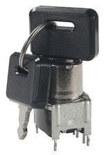
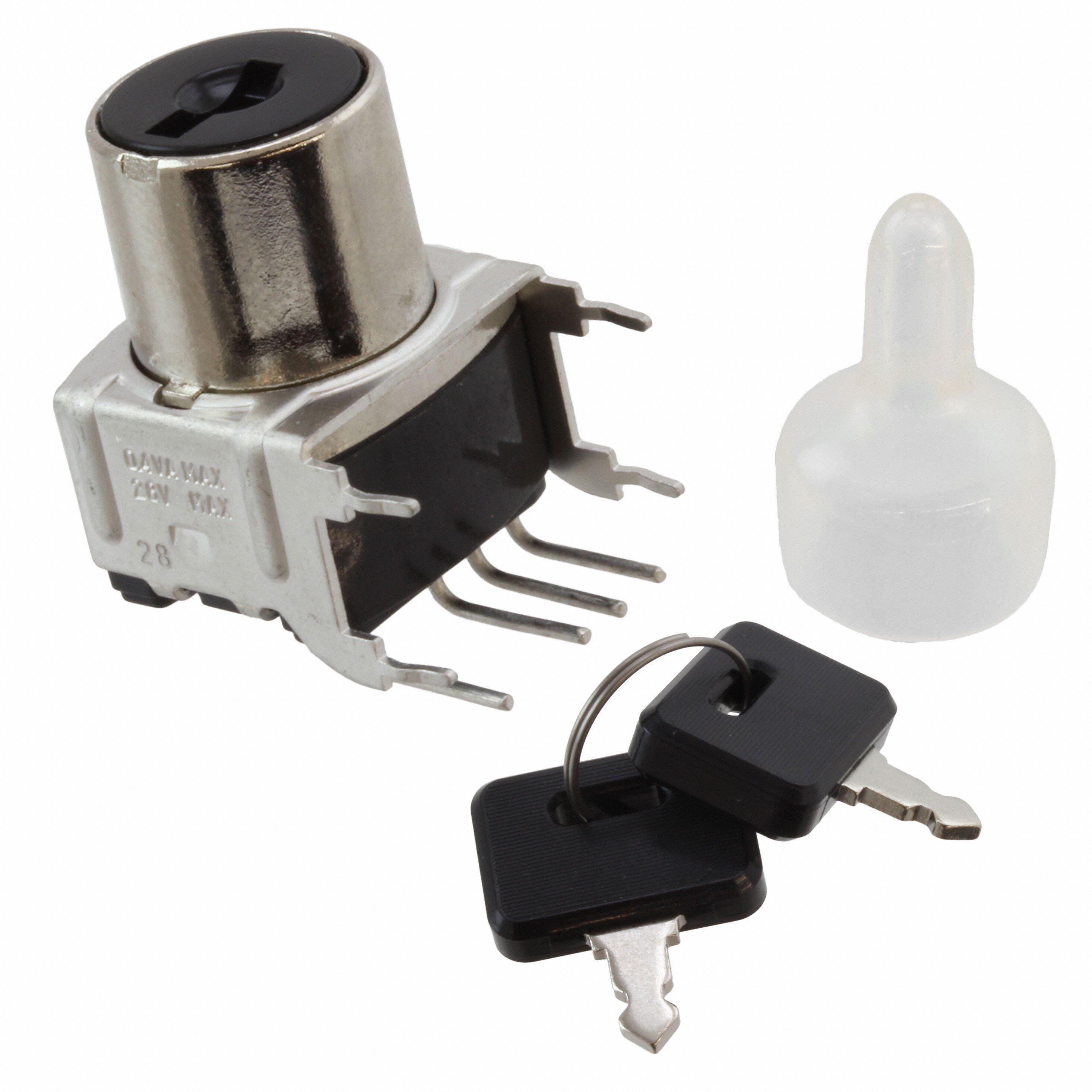
| 描述 | SWITCH KEYLOCK SP3T STR PC 28V |
| 产品分类 | |
| 品牌 | NKK Switches |
| 数据手册 | |
| 产品图片 |
|
| 产品型号 | SK14EG13 |
| PCN设计/规格 | |
| rohs | 无铅 / 符合限制有害物质指令(RoHS)规范要求 |
| RoHS指令信息 | |
| 产品系列 | SK |
| 不同电压时的触头额定电流 | 0.4VA @ 28VAC/DC |
| 产品培训模块 | http://www.digikey.cn/PTM/IndividualPTM.page?site=cn&lang=zhs&ptm=7079http://www.digikey.cn/PTM/IndividualPTM.page?site=cn&lang=zhs&ptm=30248http://www.digikey.cn/PTM/IndividualPTM.page?site=cn&lang=zhs&ptm=30583 |
| 其它名称 | 360-1474 |
| 安装类型 | 通孔 |
| 抛射角 | 45° |
| 标准包装 | 50 |
| 电路 | SP3T |
| 相关产品 | /product-detail/zh/AT4080/360-1009-ND/379096 |
| 端子类型 | PC 引脚 |
| 致动器类型 | 扁平按键 |
| 针脚数 | 3 |
| 钥匙拔出位置 | 仅 2 |


- 商务部:美国ITC正式对集成电路等产品启动337调查
- 曝三星4nm工艺存在良率问题 高通将骁龙8 Gen1或转产台积电
- 太阳诱电将投资9.5亿元在常州建新厂生产MLCC 预计2023年完工
- 英特尔发布欧洲新工厂建设计划 深化IDM 2.0 战略
- 台积电先进制程称霸业界 有大客户加持明年业绩稳了
- 达到5530亿美元!SIA预计今年全球半导体销售额将创下新高
- 英特尔拟将自动驾驶子公司Mobileye上市 估值或超500亿美元
- 三星加码芯片和SET,合并消费电子和移动部门,撤换高东真等 CEO
- 三星电子宣布重大人事变动 还合并消费电子和移动部门
- 海关总署:前11个月进口集成电路产品价值2.52万亿元 增长14.8%


PDF Datasheet 数据手册内容提取
Series SK Process Sealed Keylocks s e gl General Specifications g o T s er k c o R Electrical Capacity (Resistive Load) Logic Level: 0.4VA maximum @ 28V AC/DC maximum s (Applicable Range 0.1mA ~ 0.1A @ 20mV ~ 28V) on See Supplement section to find explanation of operating range butt h s u P B Other Ratings P d Contact Resistance: 80 milliohms maximum ate n Insulation Resistance: 100 megohms minimum @ 500V DC mi u Dielectric Strength: 500V AC minimum for 1 minute minimum Ill Mechanical Life: 30,000 cycles minimum e bl Electrical Life: 10,000 cycles minimum ma m Nominal Operating Torque: .026Nm (.234 lb•in) for momentary action models gra .020Nm (.182 lb•in) for maintained action models Pro Contact Timing: Break-before-make Angle of Throw: 90° for 2-position & 45° for 3-position s k F oc yl e K Materials & Finishes Boot: Polyvinyl chloride s Key: Brass alloy with bright nickel plating; arie brass alloy with bright nickel plating & ABS resin handle ot R Tumbler Barrel: Polyacetal Bushing: Zinc alloy with nickel plating Bracket: Steel with tin plating s e Base: Glass fiber reinforced polyamide d Sli Movable Contactor: Beryllium copper with gold plating Stationary Contacts: Copper with gold plating Terminals: Brass with tin plating s e ctil a T Environmental Data Operating Temperature Range: –25°C through +70°C (–13°F through +158°F) Humidity: 90 ~ 95% humidity for 240 hours @ 40°C (104°F) Vibration: 10 ~ 55Hz with peak-to-peak amplitude of 1.5mm traversing the frequency range & returning Tilt in 1 minute; 3 right angled directions for 2 hours Shock: 50G (490m/s2) acceleration (tested in 6 right angled directions, with 5 shocks in each direction) h c u o PCB Processing T Soldering: Wave Soldering recommended: See Profile B in Supplement section. Manual Soldering: See Profile B in Supplement section. s or Cleaning: Automated cleaning. Boot must be on switch during processing. at c See Cleaning specifications in Supplement section. di n I s e Standards & Certifications ori s These SK Series devices have not been tested for UL recognition or CSA certification. s e c These switches are designed for use in a low-voltage, low-current, logic-level circuit. Ac When used as intended in a logic-level circuit, the results do not produce hazardous energy. nt e m e pl p u S www.nkkswitches.com F19
Series SK Process Sealed Keylocks s e gl g Distinctive Characteristics o T s er k c o R Sealed body construction plus disposable boot protect contacts and allow automated processing. s n o utt b h s u P Molded-in terminals seal out flux, solvents, and PB other contaminants. d e at n mi u Ill Short body size for space-saving, behind panel e abl dimensions. m m a gr o Pr Detent mechanism, with its spring-operated ks steel ball, gives crisp, positive action for oc F yl accurate switch setting. e K s arie Bifurcated, self-wiping contact mechanism ot provides unequalled logic-level reliability R and smoother, positive detent actuation. s e d Sli Crimped bracket legs ensure secure PCB mounting and prevent dislodging during s automated wave soldering. e ctil a T .100” x .100” (2.54mm x 2.54mm) terminal Tilt ssppaacciinngg .conforms to standard PC board grid ch Actual Size u o T s or at c di n I s e ori s s e c c A nt e m e pl p u S F20 www.nkkswitches.com
Series SK Process Sealed Keylocks s e TYPICAL SWITCH ORDERING EXAMPLE gl g o T s er k c o SK 2 4E G 30 R s n o utt b h s u P B P Poles Contact Material d e at SPDT Gold Rated 0.4VA n 1 G mi SP3T @ 28V AC/DC u Ill DPDT e 2 bl DP3T a m m a gr o Pr Circuits & Key-Removable Positions PC Terminals s k Code Pos. 1 Pos. 2 Pos. 3 Key Removes 13 Straight with Bracket F oc yl e 2A ON NONE ON Positions 1 and 3 30 Right Angle K 2B ON NONE ON Position 1 s 5B ON NONE (ON) Position 1 e ari *4D ON ON ON Positions 1, 2, 3 ot R *4E ON ON ON Position 2 ( ) = Momentary s *Can be used as ON-OFF-ON circuit de Sli s e ctil a T DESCRIPTION FOR TYPICAL ORDERING EXAMPLE Tilt SK24EG30 h c Gold Contacts Rated 0.4VA ou T DP3T ON-ON-ON Circuit Right Angle PC Terminals Key Removable in Position 2 s or at c di n I 2 Keys Supplied with each Switch s e ori s s e c c A nt e m e pl p u S www.nkkswitches.com F21
Series SK Process Sealed Keylocks s e gl POLES, CIRCUITS & KEY-REMOVABLE POSITIONS g o T Connected Terminals = Key Removable Key Positions Pole & (Terminal numbers are not on switch) • = Not Removable ers Throw Model Pos 1 Pos 2 Pos 3 Pos 1 Pos 2 Pos 3 Schematic = Maximum Arc k oc POS 1 R ____ C1 SPDT SK12A ON NONE ON C1-1 C1-2 3 s button SSPPDDTT SSKK1125BB OONN NNOONNEE (OONN) C1-1 ____ C1-2 1 2 POS 1 h 3 s u P C1-1 ____ C1-2 POS 1 d PB DPDT SK22A ON NONE ON C2-4 C2-5 C1 C2 3 e at min DPDT SK22B ON NONE ON C1-1 ____ C1-2 POS 1 Illu DPDT SK25B ON NONE (ON) C2-4 C2-5 1 2 4 5 3 e bl a 2 mm SP3T SK14D ON ON ON C1-1 C1-2 C1-3 C1 POS 1 3 a gr o Pr 2 s SP3T SK14E ON ON ON C1-1 C1-2 C1-3 1 2 3 POS 1 3 k oc F eyl 2 K C1-1 C1-2 C1-3 C1 C2 POS 1 3 DP3T SK24D ON ON ON C2-4 C2-5 C2-6 s 2 otarie DP3T SK24E ON ON ON CC12--14 CC12--25 CC12--36 1 2 3 4 5 6 POS 1 3 R KEY REMOVABLE s e d Sli Positions 1 & 3 Position 1 Positions 1, 2 & 3 Position 2 A B D E 90° Angular Throw 90° Angular Throw 45° Angular Throw 45° Angular Throw s e ctil a T CONTACT MATERIAL & RATING Tilt G Gold over Copper Logic Level 0.4VA maximum @ 28V AC/DC maximum TERMINALS h c u o T 13 30 Straight PC Terminals with Bracket Right Angle PC Terminals s or at dic Double Throw Model Three Throw Model Double Throw Model Three Throw Model n I s e ori s s e c c A nt e m e pl p u S F22 www.nkkswitches.com
Series SK Process Sealed Keylocks s e KEYS gl g o T AT4080 Standard (20.0) Antistatic Plastic Handle .787 (.519.07) ers k Brass Alloy with Bright Nickel Plating oc R & ABS Resin Handle (14.5) (1.5) .571 s 2 keys supplied with each switch .059 PCB n (10.1) o .398 Suitable for all Straight PCB mount and for Right Angle utt b h PCB mount where clearance for key is obtainable. s u P B AT4079 for Right Angle Mid-board Mounting (16.0) d P (Optional) All Metal .630 ate n mi Brass Alloy with Bright Nickel Plating Illu (14.0) e .551 bl Contact factory if metal keys needed a (1.5) (8.8) (2.0) m .059 .346 .079 PCB m a gr o Disposable Boot Pr Each switch is supplied with a boot that provides protection from s k automated soldering and the cleaning process. Attach the boot F oc yl without the key installed in the switch. e K The boot is not reusable; discard after the washing procedure. s Polyvinyl Chloride arie ot R TYPICAL SWITCH DIMENSIONS Single & Double Pole Straight PC with Bracket • Double Throw s e d Sli POS 1 (0.5) Typ (0.7) Dia Typ .020 .028 (2.54) 90° .100 es . 0(13.09) 21 45 actil (12.0) Dia (15.74) T .472 POS 3 (20.0) (5.08) Typ .620 .787 .200 C1 C2 (2.54) Typ (.311.08) (.00.132) .100 (.00.278) Typ Tilt (14.5) (14.8) (10.5) (10.5) (3.5) (10.16) .571 .583 .413 .413 .138 .400 Single Pole models have only terminals 1, 2 & C1 SK12AG13 h c u o T Single & Double Pole Straight PC with Bracket • Three Throw s POS 2 (0.5) Typ (0.7) Dia Typ or .020 .028 at POS 1 45° 45° POS 3 (2.1.0504) ndic 4 I (1.0) 1 (12.0) Dia .039 2 5 (15.74) s .472 (2.708.07) (.52.0008) Typ 3 6 .620 orie C1 C2 s s e (2.54) Typ cc (3.0) (0.3) .100 (0.7) Typ A .118 .012 .028 (1.547.51) (.1548.83) (.1401.35) (1.401.53) (.313.58) (1.400.106) nt e m e pl Single Pole models have only terminals 1, 2, 3 & C1 SK24DG13 p u S www.nkkswitches.com F23
Series SK Process Sealed Keylocks s e gl TYPICAL SWITCH DIMENSIONS g o T Right Angle Key in Position 1 Single Pole PC Terminals s er Double Throw ck (5.0) (16.3) o .197 .642 R (9.0) .354 ons ( 1.04.153) 1 2 C1 utt (12.0) Dia POS 1 (0.7) Typ (0.7) Dia (2.54) Typ (3.5) hb .472 .028 .028 .100 .138 s (14.8) (12.4) (7.62) (2.54) (2.54) (5.08) Pu .583 .488 .300 .100 .100 .200 B minated P (.00.250) Typ (15.P2O4)S 3 90° (20.0.)(01.309) 4 5 C2 (.1664.32) Illu .600 .787 .(395.04) e bl mma (.311.08) (2.54) Typ 1 2 C1 (0.7) Dia Typ .(133.58) ogra .100 (2.54) .(052.088) Pr .100 .200 SK15BG30 Key in Position 3 Double Pole s k oc F Right Angle Key in Position 2 Single Pole yl Ke PC Terminals Three Throw (5.0) (16.3) s .197 .642 e (9.0) ari .354 ot POS 1 R (10.5) 1 2 3 C1 .413 45° (0.7) Typ (0.7) Dia (2.54) Typ (3.5) (12.0) Dia .028 .028 .100 .138 s .472 POS 2 (14.8) (12.4) (7.62) (2.54) (2.54) (5.08) Slide 45° .583 .488 .300 .100 .100 4 5 6 C2 .200 POS 3 (16.3) (0.5) Typ .642 es .020 (9.0) ctil ( 1.650.204) .354 a T (3.0) 1 2 3 C1 .118 (3.5) (2.54) Typ (0.7) Dia Typ.138 .100 .028 (2.54) (5.08) Tilt SK24EG30 Key in Position 1 .100Double Pole.2 00 Straight PC Footprints (2.54) Typ (2.54) Typ (2.54) Typ (2.54) Typ h .100 .100 .100 .100 c ou 1 4 1 1 4 1 T SPDT 2 DPDT 5 2 SP3T 2 DP3T 5 2 (15.24) (15.24) 3 6 3 .600 (5.08) .600 (5.08) (5.08) (5.08) C1 .200 C2 C1 .200 C1 .200 C2 C1 .200 s or at (10.16) (0.8) Dia Typ (10.16) (0.8) Dia Typ (10.16) (0.8) Dia Typ (10.16) (0.8) Dia Typ dic .400 .031 .400 .031 .400 .031 .400 .031 n I Right Angle PC Footprints s orie (2.54) (2.54) Typ ( 2.1.0504) ( 2.1.0504) Typ (2.54) (2.54) Typ ( 2.1.0504) ( 2.1.0504) Typ Access SPDT ( 5.2.0080) .10C01 2 1 .100( 2.1.0504) DPDT ( 5.2.0080) CC21 52 14 ( 2.1.0504) SP3T ( 5.2.0080) .10C01 3 2 1 .100( 2.1.0504) DP3T ( 5.2.0080) CC21 36 52 14 ( 2.1.0504) nt (7.62) (7.62) (7.62) (7.62) e .300 .300 .300 .300 m e ppl CL ( 0.0.83)1 Dia Typ CL ( 0.0.83)1 Dia Typ CL ( 0.0.83)1 Dia Typ CL ( 0.0.83)1 Dia Typ u S F24 www.nkkswitches.com
Mouser Electronics Authorized Distributor Click to View Pricing, Inventory, Delivery & Lifecycle Information: N KK Switches: SK22AG13-RO SK15BG30 SK22BG30 SK15BG13 SK24EG13 SK12AG13 SK24DG30 SK24EG30 SK24DG13 SK14DG30 SK22BG13 SK14DG13 SK12BG30 SK12AG30 SK14EG13 SK22AG30 SK12BG13 SK22AG13