ICGOO在线商城 > 射频/IF 和 RFID > RF 收发器模块 > XBP9B-DMUT-002
 Datasheet下载
- 型号: XBP9B-DMUT-002
- 制造商: DIGI INTERNATIONAL
- 库位|库存: xxxx|xxxx
- 要求:
| 数量阶梯 | 香港交货 | 国内含税 |
| +xxxx | $xxxx | ¥xxxx |
查看当月历史价格
查看今年历史价格
XBP9B-DMUT-002产品简介:
ICGOO电子元器件商城为您提供XBP9B-DMUT-002由DIGI INTERNATIONAL设计生产,在icgoo商城现货销售,并且可以通过原厂、代理商等渠道进行代购。 XBP9B-DMUT-002价格参考。DIGI INTERNATIONALXBP9B-DMUT-002封装/规格:RF 收发器模块, 。您可以下载XBP9B-DMUT-002参考资料、Datasheet数据手册功能说明书,资料中有XBP9B-DMUT-002 详细功能的应用电路图电压和使用方法及教程。
Digi International的XBP9B-DMUT-002是一款基于XBee 900MHz RF技术的收发器模块,适用于低功耗、远距离无线通信场景。以下是该型号的主要应用场景:

 1. 工业自动化
   - 设备监控:用于远程监控工业设备的状态(如温度、压力、振动等),并将数据传输到中央控制系统。
   - 传感器网络:构建无线传感器网络,实时采集和传输环境数据(如湿度、气体浓度等)。
   - 机器间通信:实现工厂内不同设备之间的无线通信,优化生产流程。

 2. 农业与环境监测
   - 精准农业:通过部署在农田中的传感器节点,实时监测土壤湿度、光照强度等数据,帮助农民优化灌溉和施肥策略。
   - 气象站:用于气象数据的采集和传输,支持天气预报或灾害预警系统。
   - 水资源管理:监测水位、水质参数,并将数据发送到远程服务器进行分析。

 3. 智能家居与楼宇自动化
   - 家庭自动化:控制照明、窗帘、空调等家用设备,支持智能家居系统的无线通信需求。
   - 能源管理:监控电表、水表和燃气表的使用情况,实现能耗优化。
   - 安防系统:连接门窗传感器、摄像头等设备,实时传输报警信号。

 4. 医疗健康
   - 远程健康监测:通过可穿戴设备或医疗传感器,实时收集患者的生命体征数据(如心率、血氧水平等),并传输至医生或监护平台。
   - 资产追踪:在医院内对医疗设备或药品进行定位和追踪。

 5. 物流与资产管理
   - 货物追踪:在仓库或运输过程中,实时跟踪货物位置和状态(如温湿度条件)。
   - 库存管理:自动更新库存信息,减少人工干预。

 6. 远程控制与数据采集
   - 野外设备控制:在偏远地区控制水泵、阀门或其他机械设备。
   - 科学实验:用于野外科研项目中的数据采集和传输。

 技术优势
- 低功耗设计:适合电池供电的应用场景,延长设备运行时间。
- 长距离通信:工作在900MHz频段,具有较强的穿透能力和较远的传输距离。
- 高可靠性:抗干扰能力强,适合复杂电磁环境下的应用。

综上所述,XBP9B-DMUT-002模块凭借其低功耗、远距离和高可靠性的特点,广泛应用于工业、农业、医疗、智能家居等多个领域,为各类无线通信需求提供了解决方案。
| 参数 | 数值 |
| 产品目录 | |
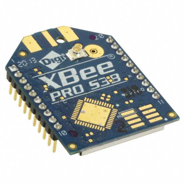
| 描述 | MODULE XBEE PRO S3B 900HP U.FLZigbee/802.15.4模块 XBeePRO900HP,200Kbps DigiMesh, U.FL |
| 产品分类 | RF 收发器射频/无线模块 |
| 品牌 | Digi International |
| 产品手册 | |
| 产品图片 |
|
| rohs | 符合RoHS无铅 / 符合限制有害物质指令(RoHS)规范要求 |
| 产品系列 | Zigbee/802.15.4模块,Digi International XBP9B-DMUT-002XBEE-PRO™ |
| mouser_ship_limit | 根据美国政府的出口法规规定,Mouser无法将此产品销售到您所在的国家。 |
| 数据手册 | |
| 产品型号 | XBP9B-DMUT-002 |
| RoHS指令信息 | |
| 产品种类 | Zigbee/802.15.4模块 |
| 传输供电电流 | 215 mA |
| 其它名称 | 602-1300 |
| 其它有关文件 | |
| 功率-输出 | 24dBm |
| 包装 | 散装 |
| 商标 | Digi International |
| 天线连接器 | U.FL |
| 天线连接器类型 | U.FL |
| 存储容量 | - |
| 封装/外壳 | 模块 |
| 尺寸 | 32.9 mm x 24.4 mm x 5.46 mm |
| 工作温度 | -40°C ~ 85°C |
| 工作电源电压 | 2.1 V to 3.6 V |
| 应用 | 无线网状网络 |
| 接收供电电流 | 29 ma |
| 数据接口 | PCB,通孔 |
| 数据速率 | 200 kbps |
| 数据速率(最大值) | 200kbps |
| 最大工作温度 | + 85 C |
| 最小工作温度 | - 40 C |
| 标准包装 | 1 |
| 灵敏度 | - 101 dBm |
| 电压-电源 | 2.1 V ~ 3.6 V |
| 电流-传输 | 215mA |
| 电流-接收 | 29mA |
| 视线范围 | 2000 ft, 9 miles |
| 调制或协议 | FHSS |
| 输出功率 | 24 dBm |
| 频带 | 902 MHz to 928 MHz |
| 频率 | 900MHz |


- 商务部:美国ITC正式对集成电路等产品启动337调查
- 曝三星4nm工艺存在良率问题 高通将骁龙8 Gen1或转产台积电
- 太阳诱电将投资9.5亿元在常州建新厂生产MLCC 预计2023年完工
- 英特尔发布欧洲新工厂建设计划 深化IDM 2.0 战略
- 台积电先进制程称霸业界 有大客户加持明年业绩稳了
- 达到5530亿美元!SIA预计今年全球半导体销售额将创下新高
- 英特尔拟将自动驾驶子公司Mobileye上市 估值或超500亿美元
- 三星加码芯片和SET,合并消费电子和移动部门,撤换高东真等 CEO
- 三星电子宣布重大人事变动 还合并消费电子和移动部门
- 海关总署:前11个月进口集成电路产品价值2.52万亿元 增长14.8%


PDF Datasheet 数据手册内容提取
XBee-PRO 900HP/XSC RF Modules S3 and S3B User Guide
Revision history—90002173 Revision Date Description P December Editorialchanges.Addedarelatedpublicationstable.Updatedthe 2014 timestampinformationfortheRouteinformationpacket. R May2015 RemovedtheWarrantysectionandaddedalink.UpdatedtheSYcommand information.CorrectedtheGTparameterrange.AddedMexicoIFETEL information. S October ReplacedtheProgrammablebootloadersectionwiththeProgrammable 2016 XBeeSDKsection.Updatedtheindoorrangespec.CorrectedtheSP andST parameterdefaultvalues. T May2018 Addednoteonrangeestimation.ChangedIC toISED. U July2018 Addedthe0x00,0x80and0x89framesforthe900HP. Trademarks and copyright Digi,DigiInternational,andtheDigilogoaretrademarksorregisteredtrademarksintheUnited Statesandothercountriesworldwide.Allothertrademarksmentionedinthisdocumentarethe propertyoftheirrespectiveowners. ©2018DigiInternationalInc.Allrightsreserved. Disclaimers Informationinthisdocumentissubjecttochangewithoutnoticeanddoesnotrepresenta commitmentonthepartofDigiInternational.Digiprovidesthisdocument“asis,”withoutwarrantyof anykind,expressedorimplied,including,butnotlimitedto,theimpliedwarrantiesoffitnessor merchantabilityforaparticularpurpose.Digimaymakeimprovementsand/orchangesinthismanual orintheproduct(s)and/ortheprogram(s)describedinthismanualatanytime. Warranty Toviewproductwarrantyinformation,gotothefollowingwebsite: www.digi.com/howtobuy/terms Customer support Gathersupportinformation:BeforecontactingDigitechnicalsupportforhelp,gatherthefollowing information: Productnameandmodel Productserialnumber(s) Firmwareversion Operatingsystem/browser(ifapplicable) XBee-PRO900HP/XSCRFModules 2
Logs(fromtimeofreportedissue) Trace(ifpossible) Descriptionofissue Stepstoreproduce ContactDigi technical support:Digioffersmultipletechnicalsupportplansandservicepackages. Contactusat+1952.912.3444orvisitusatwww.digi.com/support. Feedback Toprovidefeedbackonthisdocument,emailyourcommentsto techcomm@digi.com Includethedocumenttitleandpartnumber(XBee-PRO900HP/XSCRFModules,90002173T)inthe subjectlineofyouremail. XBee-PRO900HP/XSCRFModules 3
Contents About the XBee-PRO 900HP RF Module Userguidestructure 13 Technical specifications Performancespecifications 16 Powerrequirements 16 Generalspecifications 17 Networkingspecifications 17 Regulatoryconformitysummary 17 Serialcommunicationspecifications 18 UARTpinassignments 18 SPIpinassignments 18 GPIOspecifications 18 Secondaryprocessorspecifications 19 Hardware Mechanicaldrawings 22 Pinsignals 23 Designnotes 25 Powersupplydesign 25 Boardlayout 25 Antennaperformance 25 Recommendedpinconnections 26 Moduleoperationfortheprogrammablevariant 27 ProgrammableXBeeSDK 29 Configure the XBee-PRO 900HP RF Module Softwarelibraries 31 ConfigurethedeviceusingXCTU 31 Over-the-airfirmwareupdates 31 Distributethenewapplication 31 Verifythenewapplication 32 Installtheapplication 32 XBee-PRO900HP/XSCRFModules 4
Operation Basicoperationaldesign 35 Serialinterface 35 UARTdataflow 35 Serialdata 36 Configurationconsiderations 36 Selecttheserialport 36 ForceUARToperation 37 SelecttheSPIport 37 Serialportselection 38 Serialreceivebuffer 38 Serialtransmitbuffer 38 UARTflowcontrol 38 CTSflowcontrol 38 RTSflowcontrol 38 SPI operation SPIcommunications 41 SPIimplementation 41 SPIsignals 42 Fullduplexoperation 42 Lowpoweroperation 43 SPIandAPImode 43 SPIparameters 44 Modes Serialmodes 46 Transparentoperatingmode 46 APIoperatingmode 46 ComparingTransparentandAPImodes 46 Modesofoperation 48 Idlemode 48 Transmitmode 48 Receivemode 48 Commandmode 48 Sleepmode 51 Sleep modes Aboutsleepmodes 53 Asynchronousmodes 53 Synchronousmodes 53 Normalmode 53 Asynchronouspinsleepmode 54 Asynchronouscyclicsleepmode 54 Asynchronouscyclicsleepwithpinwakeupmode 54 Synchronoussleepsupportmode 54 Synchronouscyclicsleepmode 55 Thesleeptimer 55 Indirectmessagingandpolling 55 XBee-PRO900HP/XSCRFModules 5
Indirectmessaging 55 Polling 56 Sleepingrouters 56 SleepcoordinatorsleepmodesintheDigiMeshnetwork 56 Synchronizationmessages 57 Becomeasleepcoordinator 59 Selectsleepparameters 61 Startasleepingsynchronousnetwork 61 Addanewnodetoanexistingnetwork 62 Changesleepparameters 63 Rejoinnodesthatlosesync 63 Diagnostics 64 Querysleepcycle 64 Sleepstatus 64 Missedsyncmessagescommand 65 SleepstatusAPImessages 65 Networking methods TheMACandPHYlayers 67 64-bitaddresses 67 Makeaunicasttransmission 68 Makeabroadcasttransmission 68 Deliverymethods 68 PointtoPoint/PointtoMultipoint(P2MP) 68 Repeater/directedbroadcast 69 DigiMeshnetworking 70 AT commands Specialcommands 75 AC(ApplyChanges) 75 FR(ForceReset) 75 RE(RestoreDefaults) 75 WR(Write) 75 MAC/PHYcommands 76 AF(AvailableFrequencies) 76 CM(ChannelMask) 76 MF(MinimumFrequencyCount) 77 HP(PreambleID) 77 ID(NetworkID) 77 MT (BroadcastMulti-Transmits) 78 PL(TXPowerLevel) 78 RR(UnicastMacRetries) 78 ED(EnergyDetect) 79 Diagnosticcommands 79 BC(BytesTransmitted) 79 DB(LastPacketRSSI) 79 ER(ReceivedErrorCount) 80 GD(GoodPacketsReceived) 80 EA(MACACKFailureCount) 80 TR(TransmissionFailureCount) 80 UA(MACUnicastTransmissionCount) 81 %H(MACUnicastOneHopTime) 81 XBee-PRO900HP/XSCRFModules 6
%8(MACBroadcastOneHopTime) 81 Networkcommands 81 CE(NodeMessagingOptions) 81 BH(BroadcastHops) 82 NH(NetworkHops) 82 NN(NetworkDelaySlots) 83 MR(MeshUnicastRetries) 83 RN(DelaySlots) 83 Addressingcommands 84 SH(SerialNumberHigh) 84 SL(SerialNumberLow) 84 DH(DestinationAddressHigh) 84 DL(DestinationAddressLow) 84 TO(TransmitOptions) 85 NI(NodeIdentifier) 86 NT(NodeDiscoverTime) 86 NO(NodeDiscoveryOptions) 86 CI(ClusterID) 87 DE(DestinationEndpoint) 87 SE(SourceEndpoint) 87 Addressingdiscovery/configurationcommands 87 AG(AggregatorSupport) 87 DN(DiscoverNode) 88 ND(NetworkDiscover) 88 FN(FindNeighbors) 89 Securitycommands 90 EE(SecurityEnable) 90 KY(AESEncryptionKey) 90 Serialinterfacingcommands 90 BD(BaudRate) 90 NB(Parity) 91 SB(StopBits) 91 RO(PacketizationTimeout) 92 FT(FlowControlThreshold) 92 AP(APIMode) 92 AO(APIOptions) 93 I/Osettingscommands 93 CB(CommissioningPushbutton) 93 D0(DIO0/AD0) 93 D1(DIO1/AD1) 94 D2(DIO2/AD2) 94 D3(DIO3/AD3) 95 D4(DIO4) 95 D5(DIO5/ASSOCIATED_INDICATOR) 96 D6(DIO6/RTS) 96 D7(DIO7/CTS) 97 D8(DIO8/SLEEP_REQUEST) 97 D9(DIO9/ON_SLEEP) 98 P0(DIO10/RSSI/PWM0Configuration) 98 P1(DIO11/PWM1Configuration) 99 P2(DIO12Configuration) 99 P3(DIO13/DOUT) 100 P4(DIO14/DIN) 100 PD(PullUp/DownDirection) 100 PR(Pull-up/DownResistorEnable) 101 XBee-PRO900HP/XSCRFModules 7
M0(PWM0DutyCycle) 102 M1(PWM1DutyCycle) 103 LTcommand 103 RP(RSSIPWMTimer) 103 I/Osamplingcommands 103 AV(AnalogVoltageReference) 103 IC(DIOChangeDetection) 104 IF(SleepSampleRate) 105 IR(I/OSampleRate) 105 IS(ForceSample) 106 TP(BoardTemperature) 106 %V(VoltageSupplyMonitoring) 107 Sleepcommands 107 SM(SleepMode) 107 SO(SleepOptions) 107 SN(NumberofSleepPeriods) 108 SP(SleepPeriod) 108 ST(WakeTime) 109 WH(WakeHostDelay) 109 Diagnostic-sleepstatus/timingcommands 109 SS(SleepStatus) 109 OS(OperatingSleepTime) 110 OW(OperatingWakeTime) 110 MS(MissedSyncMessages) 110 SQ(MissedSleepSyncCount) 111 Commandmodeoptions 111 CC(CommandCharacter) 111 CN(ExitCommandMode) 111 CT(CommandModeTimeout) 111 GT(GuardTimes) 112 Firmwarecommands 112 VL(VersionLong) 112 VR(FirmwareVersion) 112 HV(HardwareVersion) 112 HS(HardwareSeries) 113 DD(DeviceTypeIdentifier) 113 NP(MaximumPacketPayloadBytes) 113 CK(ConfigurationCRC) 113 Operate in API mode APImodeoverview 116 APIframeformat 116 APIoperation(APparameter=1) 116 APIoperation-withescapedcharacters(APparameter=2) 116 Databytesthatneedtobeescaped: 117 Length 117 Framedata 117 APIserialexchanges 118 ATcommands 118 TransmitandReceiveRFdata 119 RemoteATcommands 119 DeviceRegistration 120 Calculateandverifychecksums 120 Example 120 XBee-PRO900HP/XSCRFModules 8
Frame descriptions LegacyTXRequestframe-0x00 122 ATCommandframe-0x08 123 ATCommand-QueueParameterValueframe-0x09 125 TransmitRequestframe-0x10 127 ExplicitAddressingCommandframe-0x11 130 RemoteATCommandRequestframe-0x17 133 LegacyRXIndicatorframe-0x80 135 ATCommandResponseframe-0x88 137 TXStatusframe-0x89 139 ModemStatusframe-0x8A 140 TransmitStatusframe-0x8B 141 RouteInformationPacketframe-0x8D 143 AggregateAddressingUpdateframe-0x8E 146 ReceivePacketframe-0x90 148 ExplicitRxIndicatorframe-0x91 150 I/ODataSampleRxIndicatorframe-0x92 153 NodeIdentificationIndicatorframe-0x95 155 RemoteCommandResponseframe-0x97 158 Advanced application features Remoteconfigurationcommands 161 Sendaremotecommand 161 Applychangesonremotedevices 161 Remotecommandresponses 161 Networkcommissioninganddiagnostics 161 Configuredevices 161 Networklinkestablishmentandmaintenance 162 Placedevices 163 Devicediscovery 163 Linkreliability 164 CommissioningpushbuttonandassociateLED 166 I/Olinemonitoring 169 I/Osamples 169 Queriedsampling 169 PeriodicI/Osampling 172 DetectdigitalI/Ochanges 172 General Purpose Flash Memory GeneralPurposeFlashMemory 174 AccessGeneralPurposeFlashMemory 174 GeneralPurposeFlashMemorycommands 175 PLATFORM_INFO_REQUEST(0x00) 175 PLATFORM_INFO(0x80) 175 ERASE(0x01) 176 ERASE_RESPONSE(0x81) 176 WRITE(0x02)andERASE_THEN_WRITE(0x03) 177 WRITE_RESPONSE(0x82)andERASE_THEN_WRITE_RESPONSE(0x83) 178 READ(0x04) 178 READ_RESPONSE(0x84) 179 FIRMWARE_VERIFY(0x05)andFIRMWARE_VERIFY_AND_INSTALL(0x06) 179 XBee-PRO900HP/XSCRFModules 9
FIRMWARE_VERIFY_RESPONSE(0x85) 180 FIRMWARE_VERIFY_AND_INSTALL_RESPONSE(0x86) 180 Workwithflashmemory 181 XSC firmware XBee-PROXSCRFModuleoverview 183 Pinsignals 183 Electricalcharacteristics 184 Timingspecifications 185 XBee-PRO XSC specifications Performancespecifications 189 Powerrequirements 189 Networkingspecifications 190 Generalspecifications 190 Antennaoptions 190 Regulatoryconformitysummary 191 XBee-PRO XSC RF Module operation Serialcommunications 193 UART-interfaceddataflow 193 Serialdata 193 Flowcontrol 193 DataIn(DIN)bufferandflowcontrol 194 DataOut(DO)bufferandflowcontrol 195 Operatingmodes 195 Idlemode 195 Transmitmode 196 Receivemode 196 Sleepmode 196 Commandmode 199 Configuration and commands Programmingexamples 204 ConnectthedevicetoaPC 204 Sendbinarycommands 204 Example 204 Specialcommands 205 FR(ForceReset) 205 PL(TXPowerLevel) 205 Commandmodeoptions 205 AT(GuardTimeAfter) 206 BT(GuardTimeBefore) 206 CC(CommandSequenceCharacter) 206 CD(DO3Configuration) 207 CN(ExitCommandMode) 207 CT(CommandModeTimeout) 208 E0(EchoOff) 208 E1(EchoOn) 208 XBee-PRO900HP/XSCRFModules 10
PC(Power-uptoTransparentoperatingmode) 209 Networkingandsecuritycommands 209 AM(Auto-setMY) 209 MD(RFMode) 210 MY(SourceAddress) 210 Networkcommands 211 DT(DestinationAddress) 211 HP(PreambleID) 211 HT(TimebeforeWake-upInitializer) 212 MKcommand 212 RN(DelaySlots) 213 RR(UnicastMacRetries) 213 SY(TimeBeforeInitialization) 214 TT(StreamingLimit) 215 Serialinterfacingcommands 215 BD(InterfaceDataRate) 215 CS(DO2Configuration) 216 FL(SoftwareFlowControl) 217 FT(FlowControlThreshold) 218 NB(Parity) 218 PKcommand 218 RB(PacketizationThreshold) 219 RO(PacketizationTimeout) 219 RT(DI2Configuration) 220 Diagnosticcommands 220 ER(ReceiveCountError) 220 GD(ReceiveGoodCount) 221 RE(RestoreDefaults) 221 RP(RSSIPWMTimer) 222 RZ(DIBufferSize) 222 RS(RSSI) 223 SH(SerialNumberHigh) 223 SL(SerialNumberLow) 224 TR(TransmissionFailureCount) 224 VR(FirmwareVersion-Short) 224 Sleepcommands 225 FH(ForceWakeupInitializer) 225 HT(TimebeforeWake-upInitializer) 225 LH(WakeupInitializerTimer) 226 PW(PinWakeup) 226 SM(SleepMode) 227 ST(WakeTime) 228 Network configurations Networktopologies 230 Point-to-pointnetworks 230 Point-to-multipointnetworks 230 Peertopeernetworks 231 Addressing 232 Addressrecognition 233 Basiccommunications 233 Streamingmode(default) 233 Repeatermode 234 Acknowledgedmode 238 XBee-PRO900HP/XSCRFModules 11
S3B hardware certifications Agencycertifications-UnitedStates 242 UnitedStates(FCC) 242 OEMlabelingrequirements 242 XBee-PRO900HPandXBee-PROXSC 242 FCCnotices 242 Limitedmodularapproval 243 Fixedbasestationandmobileapplications 243 PortableapplicationsandSARtesting 244 RFexposurestatement 244 FCC-approvedantennas(900MHz) 245 AntennasapprovedforusewiththeXBee-PRO900HPRFModule 245 ISED(Innovation,ScienceandEconomicDevelopmentCanada) 251 Labelingrequirements 251 ContainsIC:1846A-XB900HP 251 Transmittersfordetachableantennas 251 Detachableantenna 251 BrazilANATEL 252 MexicoIFETEL 252 IDA(Singapore)certification 252 Labeling 252 Frequencyband 253 Antennagain 253 Legacy S3B hardware certifications Agencycertifications-UnitedStates 255 UnitedStates(FCC) 255 OEMlabelingrequirements 255 XBeePROS3 255 XBeePROS3B 255 FCCnotices 256 Limitedmodularapproval 256 Fixedbasestationandmobileapplications 257 PortableapplicationsandSARtesting 257 RFexposurestatement 257 ISED(Innovation,ScienceandEconomicDevelopmentCanada) 258 Labelingrequirements 258 ContainsIC:1846A-XB900HP 258 ContainsIC:1846A-XBEEXSCorContainsIC:1846A-XBPS3B 258 Antennaoptions:900MHzantennalistings 259 Transmitterswithdetachableantennas 264 Detachableantenna 265 BrazilANATEL 266 XBee-PRO900HP/XSCRFModules 12
About the XBee-PRO 900HP RF Module TheXBee-PRO900HPRFModulesconsistoffirmwareloadedontoXBee-PROS3Bhardware.These embeddedRFdevicesprovidewirelessconnectivitytoend-pointdevicesinmeshnetworks. Youcanbuildnetworksupto128nodesusingtheXBeedevices.Forlargernetworksofupto1,000or morenodes,weofferRFoptimizationservicestoassistwithpropernetworkconfiguration. Formoreinformationnetworkconfiguration,contactDigiTechnicalSupport. Note TheXBee-PRO900HPRFModuleisnotbackwardcompatiblewiththelegacyXBee-PRO900 (PartNumber:XBP09-DP…)orXBee-PRODigiMesh900(PartNumber:XBP09-DM…)RFmodules. TheXBee-PROS3Bhardwareconsistsof: n OneEnergyMicroEFM®32G230F128microcontroller n OneAnalogDevicesADF7023radiotransceiver n OneRFpoweramplifier n OneNXPMC9S08QE32®microcontroller,onlyintheprogrammableversionoftheXBee User guide structure ThisuserguidecontainsdocumentationfortwoRFprotocols:XStreamCompatible(XSC)and900HP. TheXSCfirmwareisprovidedforcustomerswhoneedcompatibilitywithexistingnetworksthatneed tobe9XStreamcompatible.CustomerswhodonotrequirethiscompatibilityshouldnotusetheXSC firmware,butratherthenewer900HPfirmware. TheXSCfirmwaresectionatthebackofthisuserguidecontainsdocumentationfortheXSCfirmware only.Allotherfirmwaredocumentationintheuserguideisapplicabletothe900HPfirmwareonly.For moreinformationaboutXSCfirmwareseethe XSCfirmwaresection. TheXBee-PRO900HPRFModuleisnotbackwardcompatiblewiththelegacyXBee-PRO900(Part Number:XBP09-DP…)orXBee-PRODigiMesh900(PartNumber:XBP09-DM…)RFModules. ThefollowingtabledescribeshowtousethisuserguidebasedontheDigipartnumberforthe module: XBee-PRO900HP/XSCRFModules 13
AbouttheXBee-PRO900HPRFModule Userguidestructure Pre- Digi Part Hardware installed Firmware Regulatory Numbers FCC ID Platform Firmware Available Information XBP09-XC… MCQ- S31 XSC XSC LegacyS3Bhardware XBEEXSC certifications XBP9B-XC*T-001(revisionG MCQ- S3B XSC XSC LegacyS3Bhardware andearlier) XBPS3B certifications XBP9B-XC*T-002(revisionG andearlier) XBP9B-XC*T-021(revisionF andearlier) XBP9B-XC*T-022(revisionF andearlier) XBP9B-XC*T-001(revisionH MCQ- S3B XSC XSC/ andlater) XB900HP 900HP XBP9B-XC*T-002(revisionH andlater) XBP9B-XC*T-021(revisionG andlater) XBP9B-XC*T-022(revisionG andlater) allotherpartnumbers beginningXBP9B-XC... XBP9B-D… MCQ- S3B 900HP XSC/ XB900HP 900HP 1TheS3hardwarevariantisalegacydesignthatisobsolete.NewandolddesignsshouldusetheS3Bhardware variant. XBee-PRO900HP/XSCRFModules 14
Technical specifications Performancespecifications 16 Powerrequirements 16 Generalspecifications 17 Networkingspecifications 17 Regulatoryconformitysummary 17 Serialcommunicationspecifications 18 GPIOspecifications 18 Secondaryprocessorspecifications 19 XBee-PRO900HP/XSCRFModules 15
Technicalspecifications Performancespecifications Performance specifications Thistabledescribestheperformancespecificationsforthedevices. Note Rangefigureestimatesarebasedonfree-airterrainwithlimitedsourcesofinterference.Actual rangewillvarybasedontransmittingpower,orientationoftransmitterandreceiver,heightof transmittingantenna,heightofreceivingantenna,weatherconditions,interferencesourcesinthe area,andterrainbetweenreceiverandtransmitter,includingindoorandoutdoorstructuressuchas walls,trees,buildings,hills,andmountains. Specification Value IdealRFline-of-sight 10kb/s:upto9miles(15.5km) range 200kb/s:upto4miles(6.5km) (with2.1dBdipoleantennas) Transmitpoweroutput 24dBm(250mW)(softwareselectable) RFdatarate(high) 200kb/s RFdatarate(low) 10kb/s SerialUARTinterface Complementarymetal–oxide–semiconductor(CMOS)Serialuniversal asynchronousreceiver/transmitter(UART),baudratestabilityof<1% Serialinterfacedata 9600-230400baud rate(software selectable) Receiversensitivity -101dBm,highdatarate (typical) -110dBm,lowdatarate Power requirements ThefollowingtabledescribesthepowerrequirementsfortheXBee-PRO900HPRFModule. Specification Value Supplyvoltage 2.1to3.6VDC1 Transmitcurrent PL=4:215mAtypical,(290mAmax) PL=3:160mAtypical PL=2:120mAtypical PL=1:95mAtypical PL=0:60mAtypical Idle/receivecurrent 29mAtypicalat3.3V(35mAmax) Sleepcurrent 2.5µA(typical) 1Supplyvoltagesoflessthan3.0Vmayreduceperformance.Outputpowerandreceiversensitivitymay degrade. XBee-PRO900HP/XSCRFModules 16
Technicalspecifications Generalspecifications General specifications Thefollowingtabledescribesthegeneralspecificationsforthedevices. Specification Value Operatingfrequencyband1 902to928MHz(softwareselectablechannels) Dimensions 3.29cmx2.44cmx0.546cm(1.297"x0.962"x0.215) Dimensionsdonotincludeconnector/antennaorpinlengths Weight 5to8grams,dependingontheantennaoption Operatingtemperature -40ºCto85ºC(industrial) Antennaoptions Integratedwire,U.FLRFconnector,reverse-polaritySMA connector DigitalI/O Fifteen(15)I/Olines, Analog-to-digitalconverter Four(4)10-bitanaloginputs (ADC) Networking specifications Thefollowingtableprovidesthenetworkingspecificationsforthedevice. Specification Value Supportednetworktopologies Mesh,point-to-point,point-to-multipoint,peer-to-peer Numberofchannels,userselectable 64channelsavailable channels Addressingoptions PersonalAreaNetworkidentifier(PANID),PreambleID,and 64-bitaddresses Encryption 128bitAdvancedEncryptionStandard(AES) Regulatory conformity summary Thistabledescribestheagencyapprovalsforthedevices. Country Approval UnitedStates(FCCPart15.247) MCQ-XB900HP Innovation,ScienceandEconomicDevelopmentCanada 1846A-XB900HP (ISED) 1Supplyvoltagesoflessthan3.0Vmayreduceperformance.Outputpowerandreceiversensitivitymay degrade. XBee-PRO900HP/XSCRFModules 17
Technicalspecifications Serialcommunicationspecifications Country Approval Australia RCM Brazil ANATEL3727-12-1209 Singapore LicenseNo.DA105737(XB900HP only) Mexico IFETEL(XB900HPonly) RoHS2 Compliant Serial communication specifications TheXBee-PRO900HPRFModulesupportsbothUniversalAsynchronousReceiver/Transmitter (UART)andSerialPeripheralInterface(SPI) serialconnections. UART pin assignments UARTpins Device pin number DOUT 2 DIN/CONFIG 3 CTS/DIO7 12 RTS/DIO6 16 SPI pin assignments SPIpins Device pin number SPI_SCLK/DIO18 18 SPI_SSEL/DIO17 17 SPI_MOSI/DIO16 11 SPI_MISO/DIO15 4 SPI_ATTN/DIO1 19 GPIO specifications XBeedeviceshave15GeneralPurposeInput/Output(GPIO)portsavailable.Thepreciselistdepends onthedeviceconfigurationassomedevicesusetheGPIOpinsforpurposessuchasserial communication.ThefollowingtableshowstheelectricalspecificationsfortheGPIOpins. XBee-PRO900HP/XSCRFModules 18
Technicalspecifications Secondaryprocessorspecifications GPIOelectrical specification Value Voltage-supply 2.1-3.6V(3.0Vorhigherrequiredforoptimalperformance) LowSchmittswitchingthreshold 0.3xV DD HighSchmittswitchingthreshold 0.7xV DD Inputpull-upresistorvalue 40kΩ Inputpull-downresistorvalue 40kΩ Outputvoltageforlogic0 0.05xV DD Outputvoltageforlogic1 0.95xV DD Outputsourcecurrent 2mA Outputsinkcurrent 2mA Totaloutputcurrent(forGPIOpins) 48mA Note ForinformationaboutMexicoIFETEL,seeMexicoIFETEL.OnlytheXBee-PRO900HPdevices listedareapprovedbyIFETEL. Secondary processor specifications Ifthedevicehastheprogrammablesecondaryprocessor,addthevaluesfromthefollowingtablesto thespecificationslistedinthePowerrequirementsspecifications.Formoreinformationabout transmit,receive,andsleepcurrents,seePowerrequirements. Forexample,ifthesecondaryprocessorrunsat20MHzandtheprimaryprocessorisinreceivemode, thenthenewcurrentvalueis: I =I +I =14mA+9mA=23mA total r2 rx whereI istheruntimecurrentofthesecondaryprocessorandI isthereceivecurrentofthe r2 rx primaryprocessor. Add these numbers topowerrequirement specifications (add toRX, TX, and sleep currents Optional secondary processorspecification dependingon mode of operation) Runtimecurrentfor32krunningat20MHz +14mA Runtimecurrentfor32krunningat1MHz +1mA Sleepcurrent +0.5µAtypical ForadditionalspecificationsseetheNXPdatasheet MC9S08QE32 andmanual Voltagerequirementforsecondaryprocessorto 2.4to3.6VDC operateatmaximumclockfrequency XBee-PRO900HP/XSCRFModules 19
Technicalspecifications Secondaryprocessorspecifications Add these numbers topowerrequirement specifications (add toRX, TX, and sleep currents Optional secondary processorspecification dependingon mode of operation) Minimumresetpulseforprogrammablevariant 100nS Minimumresetpulsetoradio 50nS Voltagereference(VREF)range 1.8VDCtoVCC XBee-PRO900HP/XSCRFModules 20
Hardware Mechanicaldrawings 22 Pinsignals 23 Designnotes 25 XBee-PRO900HP/XSCRFModules 21
Hardware Mechanicaldrawings Mechanical drawings ThefollowingfiguresshowthemechanicaldrawingsfortheXBee-PRO900HPRFModule.The drawingsdonotshowantennaoptions. XBee-PRO900HP/XSCRFModules 22
Hardware Pinsignals Pin signals Thefollowingtableshowsthepinsignalsandtheirdescriptions.Thetablespecifiessignaldirection withrespecttothedevice.Formoreinformationonpinconnections,seeDesignnotes. Default Pin # Name Direction state Description 1 VCC Powersupply XBee-PRO900HP/XSCRFModules 23
Hardware Pinsignals Default Pin # Name Direction state Description 2 DOUT/DIO13 Both Output GPIO/UARTdataout 3 DIN/CONFIG Both Input GPIO/UARTdatain /DIO14 4 DIO12/SPI_ Both Output GPIO/SPIslaveout MISO 5 RESET Input Devicereset.Drivelowtoresetthedevice.Thisis alsoanoutputwithanopendrainconfiguration withaninternal20kΩpull-up(neverdrivetologic high,asthedevicemaybedrivingitlow).The minimumpulsewidthis1mS. 6 DIO10/PWM0 Both GPIO/RXsignalstrengthindicator 7 DIO11/PWM1 Both GPIO/pulsewidthmodulator 8 Reserved Disabled Donotconnect 9 DTR/SLEEP_ Both Input GPIO/pinsleepcontrolline(DTRonthe RQ/DIO8 developmentboard) 10 GND Ground 11 DIO4/SPI_MOSI Both GPIO/SPIslavein 12 CTS/DIO7 Both Output GPIO/clear-to-sendflowcontrol 13 ON_SLEEP Output Output GPIO/modulestatusindicator /DIO9 14 VREF Input Internallyusedfortheprogrammablesecondary processor.ForcompatibilitywithotherXBee devices,werecommendconnectingthispintothe voltagereferenceifyoudesireanalogsampling. Otherwise,connecttoGND. 15 Associate/DIO5 Both Output GPIO/associateindicator 16 RTS/DIO6 Both Input GPIO/request-to-sendflowcontrol 17 AD3/DIO3/SPI_ Both GPIO/analoginput/SPIslaveselect SSEL 18 AD2/DIO2/SPI_ Both GPIO/analoginput/SPIclock CLK 19 AD1/DIO1/SPI_ Both GPIO/analoginput/SPIattention ATTN 20 AD0/DIO0 Both GPIO/analoginput XBee-PRO900HP/XSCRFModules 24
Hardware Designnotes Design notes TheXBeemodulesdonotrequireanyexternalcircuitryorspecificconnectionsforproperoperation. However,therearesomegeneraldesignguidelinesthatwerecommendtobuildandtroubleshoota robustdesign. Power supply design Apoorpowersupplycanleadtopoorradioperformance,especiallyifyoudonotkeepthesupply voltagewithintoleranceorifthenoiseisexcessive.Tohelpreducenoise,placea1.0µFand47pF capacitorasnearaspossibletopin1onthePCB.Ifyouareusingaswitchingregulatorforthepower supply,switchthefrequenciesabove500kHz.Limitthepowersupplyrippletoamaximum50mV peaktopeak. Fordesignsusingtheprogrammablemodules,werecommendanadditional10µFdecouplingcap nearpin1ofthedevice.Thenearestproximitytopin1ofthethreecapsshouldbeinthefollowing order: 1. 47pf 2. 1µF 3. 10µF Board layout WedesignXBeemodulestobeself-sufficientandhaveminimalsensitivitytonearbyprocessors, crystalsorotherprintedcircuitboard(PCB)components.Keeppowerandgroundtracesthickerthan signaltracesandmakesurethattheyareabletocomfortablysupportthemaximumcurrent specifications.TherearenootherspecialPCBdesignconsiderationstointegrateXBeemodules,with theexceptionofantennas. Antenna performance Antennalocationisimportantforoptimalperformance.Thefollowingsuggestionshelpyouachieve optimalantennaperformance.Pointtheantennaupvertically(upright).Antennasradiateandreceive thebestsignalperpendiculartothedirectiontheypoint,soaverticalantenna'somnidirectional radiationpatternisstrongestacrossthehorizon. Positiontheantennasawayfrommetalobjectswheneverpossible.Metalobjectsbetweenthe transmitterandreceivercanblocktheradiationpathorreducethetransmissiondistance.Objects thatareoftenoverlookedinclude: n Metalpoles n Metalstuds n Structurebeams n Concrete,whichisusuallyreinforcedwithmetalrods Ifyouplacethedeviceinsideametalenclosure,useanexternalantenna.Commonobjectsthathave metalenclosuresinclude: n Vehicles n Elevators n Ventilationducts n Refrigerators XBee-PRO900HP/XSCRFModules 25
Hardware Designnotes n Microwaveovens n Batteries n Tallelectrolyticcapacitors Usethefollowingadditionalguidelinesforoptimalantennaperformance: n DonotplaceXBeemoduleswiththechipantennainsideametalenclosure. n Donotplaceanygroundplanesormetalobjectsaboveorbelowtheantenna. n Forthebestresults,mountthedeviceattheedgeofthehostPCB.Ensurethattheground, power,andsignalplanesarevacantimmediatelybelowtheantennasection. Recommended pin connections Theonlyrequiredpinconnectionsfortwo-waycommunicationareVCC,GND,DOUTandDIN.To supportserialfirmwareupdates,youmustconnectVCC,GND,DOUT,DIN,RTS,andDTR. Donotconnectanypinsthatarenotinuse.UsethePRandPDcommandstopullallinputsonthe radiohighwithinternalpull-upresistors.Unusedoutputsdonotrequireanyspecifictreatment. Forapplicationsthatneedtoensurethelowestsleepcurrent,neverleaveunconnectedinputs floating.Useinternalorexternalpull-uporpull-downresistors,orsettheunusedI/Olinestooutputs. YoucanconnectotherpinstoexternalcircuitryforconvenienceofoperationincludingtheAssociate LEDpin(pin15)andtheCommissioningpin(pin20).TheAssociateLEDpinflashesdifferently dependingonthestateofthemodule,andapushbuttonattachedtopin20canenablevarious deploymentandtroubleshootingfunctionswithoutyousendingUARTcommands.Formore information,seeCommissioningpushbuttonandassociateLED. OnlytheprogrammableversionsofthesedevicesusetheVREFpin(pin14).Forcompatibilitywith otherXBeemodules,werecommendconnectingthispintoavoltagereferenceifyouwanttoenable analogsampling.Otherwise,connecttoGND. XBee-PRO900HP/XSCRFModules 26
X Module operation for the programmable variant H B a e r e d - Themoduleswiththeprogrammableoptionhaveasecondaryprocessorwith32kofflashand2kofRAM.Thisallowsmoduleintegratorstoputcustom w P R a O codeontheXBeemoduletofittheirownuniqueneeds.TheDIN,DOUT,RTS,CTS,andRESETlinesareinterceptedbythesecondaryprocessortoallowit re 90 tobeincontrolofthedatatransmittedandreceived.Allotherlinesareinparallelandcanbecontrolledbyeithertheinternalmicrocontrollerorthe 0 H MC9SO8QEmicro;seetheblockdiagraminOperationfordetails.Theinternalmicrocontrollerbydefaulthascontrolofcertainlines.Theinternal P /X microcontrollercanreleasetheselinesbysendingthepropercommand(s)todisablethedesiredDIOline(s).Formoreinformationaboutcommands,see S C ATcommands. R F ForthesecondaryprocessortosamplewithADCs,theXBee14(VREF)mustbeconnectedtoareferencevoltage. M od Digiprovidesabootloaderthatcantakecareofprogrammingtheprocessorover-the-airorthroughtheserialinterface.Thismeansthatover-the-air u le updatescanbesupportedthroughanXMODEMprotocol.TheprocessorcanalsobeprogrammedanddebuggedthroughaonewireinterfaceBKGD(Pin s 8). D e s ig n n o 2 te 7 s
X H B a e r e d - w P R a O re 9 0 0 H P / X S C R F M o d u le s D e s ig n n o 2 te 8 s
Hardware Designnotes Programmable XBee SDK TheXBeeProgrammablemoduleisequippedwithaNXPMC9S08QE32applicationprocessor.This applicationprocessorcomeswithasuppliedbootloader.Tointerfaceyourapplicationcoderunningon thisprocessortotheXBeeProgrammablemodule'ssuppliedbootloader,usetheProgrammableXBee SDK. TousetheSDK,youmustalsodownloadCodeWarrior.Thedownloadlinksare: n CodeWarriorIDE:http://ftp1.digi.com/support/sampleapplications/40003004_B.exe n ProgrammableXBeeSDK:http://ftp1.digi.com/support/sampleapplications/40003003_D.exe Iftheserevisionschange,searchforthepartnumberonDigi’swebsite.Forexample,searchfor 40003003. InstalltheIDEfirst,andtheninstalltheSDK. ThedocumentationfortheProgrammableXBeeSDKisbuiltintotheSDK,sotheGettingStartedguide appearswhenyouopenCodeWarrior. XBee-PRO900HP/XSCRFModules 29
Configure the XBee-PRO 900HP RF Module Softwarelibraries 31 ConfigurethedeviceusingXCTU 31 Over-the-airfirmwareupdates 31 XBee-PRO900HP/XSCRFModules 30
ConfiguretheXBee-PRO900HPRFModule Softwarelibraries Software libraries OnewaytocommunicatewiththeXBee-PRO900HPRFModuleisbyusingasoftwarelibrary.The librariesavailableforusewiththeXBee-PRO900HPRFModuleinclude: n XBeeJavalibrary n XBeePythonlibrary TheXBeeJavaLibraryisaJavaAPI.ThepackageincludestheXBeelibrary,itssourcecodeanda collectionofsamplesthathelpyoudevelopJavaapplicationstocommunicatewithyourXBeedevices. TheXBeePythonLibraryisaPythonAPIthatdramaticallyreducesthetimetomarketofXBee projectsdevelopedinPythonandfacilitatesthedevelopmentofthesetypesofapplications,makingit aneasyprocess. Configure the device using XCTU XBeeConfigurationandTestUtility(XCTU)isamulti-platformprogramthatenablesuserstointeract withDigiradiofrequency(RF)devicesthroughagraphicalinterface.Theapplicationincludesbuilt-in toolsthatmakeiteasytosetup,configure,andtestDigiRFdevices. ForinstructionsondownloadingandusingXCTU,seetheXCTUUserGuide. ClickDiscoverdevicesandfollowtheinstructions.XCTUshoulddiscovertwoXBee-PRO900HPRF Modulemodules. ClickAdd selected devices.ThedevicesappearintheRadioModuleslist.Youcanclickamoduleto viewandconfigureitsindividualsettings.Formoreinformationontheseitems,seeATcommands. Over-the-air firmware updates Therearetwomethodsofupdatingthefirmwareonthedevice.Youcanupdatethefirmwarelocally withXCTUusingthedevice'sserialportinterface.Youcanalsoupdatefirmwareusingthedevice'sRF interface(over-the-airupdating.) Theover-the-airfirmwareupdatemethodprovidedisarobustandversatiletechniquethatyoucan tailortomanydifferentnetworksandapplications.OTA updatesarereliableandminimizedisruption ofnormalnetworkoperations. Inthefollowingsections,werefertothenodethatwillbeupdatedasthetargetnode.Werefertothe nodeprovidingtheupdateinformationasthesourcenode.Inmostapplicationsthesourcenodeis locallyattachedtoacomputerrunningupdatesoftware. Therearethreephasesoftheover-the-airupdateprocess: 1. Distributethenewapplication 2. Verifythenewapplication 3. Installtheapplication Distribute the new application Thefirstphaseofperforminganover-the-airupdateonadeviceistransferringthenewfirmwarefile tothetargetnode.Loadthenewfirmwareimageinthetargetnode'sGPMpriortoinstallation.XBee- PRO900HPRFModulesuseanencryptedbinary(.ebin)fileforbothserialandover-the-airfirmware updates.ThesefirmwarefilesareavailableontheDigiSupportwebsiteandviaXCTU. Sendthecontentsofthe.ebinfiletothetargetdeviceusinggeneralpurposememoryWRITE commands.ErasetheentireGPMpriortobeginninganuploadofan.ebinfile.Thecontentsofthe.ebin XBee-PRO900HP/XSCRFModules 31
ConfiguretheXBee-PRO900HPRFModule Over-the-airfirmwareupdates fileshouldbestoredinorderintheappropriateGPMmemoryblocks.Thenumberofbytesthatare sentinanindividualGPMWRITEframeisflexibleandcanbecateredtotheuserapplication. Example Theexamplefirmwareversionhasan.ebinfileof55,141bytesinlength.Basedonnetworktraffic,we determinethatsendinga128bytepacketevery30secondsminimizesnetworkdisruption.Forthis reason,youwoulddivideandaddressthe.ebinasfollows: GPM_BLOCK_NUM GPM_START_INDEX GPM_NUM_BYTES .ebin bytes 0 0 128 0to127 0 128 128 128to255 0 256 128 256to383 0 384 128 384to511 1 0 128 512to639 1 128 128 640to767 - - - - - - - - - - - - 107 0 54784to54911 107 128 54912to55039 107 256 101 55040to55140 Verify the new application Foranuploadedapplicationtofunctioncorrectly,everysinglebytefromthe.ebinfilemustbeproperly transferredtotheGPM.Toguaranteethatthisisthecase,GPMVERIFYfunctionsexisttoensurethat allbytesareproperlyinplace.TheFIRMWARE_VERIFYfunctionreportswhetherornottheuploaded dataisvalid.TheFIRMWARE_VERIFY_AND_INSTALLcommandreportsiftheuploadeddataisinvalid.If thedataisvalid,itbeginsinstallingtheapplication.Noinstallationtakesplaceoninvaliddata. Install the application Whentheentire.ebinfileisuploadedtotheGPMofthetargetnode,youcanissueaFIRMWARE_ VERIFY_AND_INSTALLcommand.Oncethetargetreceivesthecommanditverifiesthe.ebinfile loadedintheGPM.Ifitisvalid,thenthedeviceinstallsthenewfirmware.Thisinstallationprocesscan takeuptoeightseconds.DuringtheinstallationthedeviceisunresponsivetobothserialandRF communication.Tocompletetheinstallation,thetargetmoduleresets.ATparametersettingswhich havenotbeenwrittentoflashusingtheWRcommandwillbelost. Important considerations WriteallparameterswiththeWRcommandbeforeperformingafirmwareupdate.Packetrouting informationisalsolostafterareset.RoutediscoveriesarenecessaryforDigiMeshunicastsinvolving theupdatednodeasasource,destination,orintermediatenode. XBee-PRO900HP/XSCRFModules 32
ConfiguretheXBee-PRO900HPRFModule Over-the-airfirmwareupdates BecauseexplicitAPITxframescanbeaddressedtoalocalnode(accessibleviatheSPIorUART)ora remotenode(accessibleovertheRFport)thesameprocesscanbeusedtoupdatefirmwareona deviceineithercase. XBee-PRO900HP/XSCRFModules 33
Operation Basicoperationaldesign 35 Serialinterface 35 UARTdataflow 35 Configurationconsiderations 36 Serialportselection 38 UARTflowcontrol 38 XBee-PRO900HP/XSCRFModules 34
Operation Basicoperationaldesign Basic operational design TheXBee-PRO900HPRFModuleRFModuleusesamulti-layeredfirmwarebasetoordertheflowof data,dependentonthehardwareandsoftwareconfigurationthatyouchoose.Thefollowinggraphic showsaconfigurationblockdiagram,withthehostserialinterfaceasthephysicalstartingpointand theantennaasthephysicalendpointforthetransferreddata.Aslongasoneblockcantouchanother block,thetwointerfacescaninteract.Forexample,ifthedeviceisusingSPImode,TransparentMode isnotavailable. ThecommandhandleristhecodethatprocessescommandsfromATCommandModeorApplication ProgrammingInterface(API)Mode(seeATcommands).Thecommandhandleralsoprocesses commandsfromremoteradios(seeRemoteATcommands). Serial interface TheXBee-PRO900HPRFModuleinterfacestoahostdevicethroughaserialport.Thedevicecan communicatethroughitsserialportwiththefollowing: n Logicandvoltagecompatibleuniversalasynchronousreceiver/transmitter(UART). n Leveltranslatortoanyserialdevice,forexample,throughanRS-232orUSBinterfaceboard. n SPI,asdescribedinSPIcommunications. UART data flow DevicesthathaveaUARTinterfaceconnectdirectlytothepinsoftheXBee-PRO900HPRFModuleas showninthefollowingfigure.ThefigureshowssystemdataflowinaUART-interfacedenvironment. Low-assertedsignalshaveahorizontallineoverthesignalname. XBee-PRO900HP/XSCRFModules 35
Operation Configurationconsiderations Serial data AdevicesendsdatatotheXBee-PRO900HPRFModule'sUARTthroughpin3DINasanasynchronous serialsignal.Whenthedeviceisnottransmittingdata,thesignalsshouldidlehigh. Forserialcommunicationtooccur,youmustconfiguretheUARTofbothdevices(themicrocontroller andtheXBee-PRO900HPRFModule)withcompatiblesettingsforthebaudrate,parity,startbits, stopbits,anddatabits. Eachdatabyteconsistsofastartbit(low),8databits(leastsignificantbitfirst)andastopbit(high). Thefollowingdiagramillustratestheserialbitpatternofdatapassingthroughthedevice.The diagramshowsUARTdatapacket0x1F(decimalnumber31)astransmittedthroughthedevice. YoucanconfiguretheUARTbaudrate,parity,andstopbitssettingsonthedevicewiththeBD,NB, andSBcommandsrespectively.Formoreinformation,seeSerialinterfacingcommands. Configuration considerations Theconfigurationconsiderationsare: n Howdoyouselecttheserialport?Forexample,shouldyouusetheUARTortheSPIport? n IfyouusetheSPIport,whatdataformatshouldyouuseinordertoavoidprocessinginvalid characterswhiletransmitting? n WhatSPIoptionsdoyouneedtoconfigure? Select the serial port BoththeUARTandSPIportsareconfiguredforserialportoperationbydefault. XBee-PRO900HP/XSCRFModules 36
Operation Configurationconsiderations n Ifbothinterfacesareconfigured,serialdatagoesouttheUARTuntiltheSPI_SSELsignalis asserted.Afterthat,allserialcommunicationsoperateontheSPIinterface. n IfyouenableonlytheUART,thenthedeviceonlyusestheUARTandignoresSPI_SSEL.Ifyou onlyenabletheSPI,thenthedeviceusesonlytheSPI. n Ifyoudonotenableeitherserialport,thedevicedoesnotsupportserialoperationsandall communicationsmustoccurover-the-air.Thedevicediscardsalldatathatwouldnormallygo totheserialport. Force UART operation IfyouconfigureadevicewithonlytheSPIenabledandnoSPImasterisavailabletoaccesstheSPI slaveport,youcanrecoverthedevicetoUARToperationbyholdingDIN/CONFIGlowatresettime. DIN/CONFIGforcesadefaultconfigurationontheUARTat9600baudandbringsupthedevicein CommandmodeontheUARTport.Youcanthensendtheappropriatecommandstothedeviceto configureitforUARToperation.Ifyouwritethoseparameters,thedevicecomesupwiththeUART enabledonthenextreset. Select the SPI port ToforceSPImode,holdDOUT/DIO13(pin2)lowwhileresettingthedeviceuntilSPI_ATTNasserts. ThiscausesthedevicetodisabletheUARTandgostraightintoSPIcommunicationmode.Once configurationiscomplete,thedevicequeuesamodemstatusframetotheSPIport,whichcausesthe SPI_ATTNlinetoassert.ThehostcanusethistodeterminethattheSPIportisconfiguredproperly. ThismethodforcestheconfigurationtoprovidefullSPIsupportforthefollowingparameters: n D1(Thisparameterwillonlybechangedifitisatadefaultofzerowhenthemethodis invoked.) n D2 n D3 n D4 n P2 AslongasthehostdoesnotissueaWRcommand,theseconfigurationvaluesreverttoprevious valuesafterapower-onreset.IfthehostissuesaWRcommandwhileinSPImode,thesesame parametersarewrittentoflash.Afterareset,parametersthatwereforcedandthenwrittentoflash becomethemodeofoperation. IftheUARTisdisabledandtheSPIisenabledinthewrittenconfiguration,thenthedevicecomesupin SPImodewithoutforcingitbyholdingDOUTlow.IfboththeUARTandtheSPIareenabledatthetime ofreset,thenoutputgoestotheUARTuntilthehostsendsthefirstinput.Ifthatfirstinputcomeson theSPIport,thenallsubsequentoutputgoestotheSPIportandtheUARTisdisabled.Ifthefirst inputcomesontheUART,thenallsubsequentoutputgoestotheUARTandtheSPIisdisabled. Whenthemasterassertstheslaveselect(SPI_SSEL)signal,SPItransmitdataisdriventotheoutput pinSPI_MISO,andSPIdataisreceivedfromtheinputpinSPI_MOSI.TheSPI_SSELpinhastobe assertedtoenablethetransmitserializertodrivedatatotheoutputsignalSPI_MISO.Arisingedge onSPI_SSELcausestheSPI_MISOlinetobetri-statedsuchthatanotherslavedevicecandriveit,ifso desired. Iftheoutputbufferisempty,theSPIserializertransmitsthelastvalidbitrepeatedly,whichmaybe eitherhighorlow.Otherwise,thedeviceformatsalloutputinAPImode1format,asdescribedin OperateinAPImode.Theattachedhostisexpectedtoignorealldatathatisnotpartofaformatted APIframe. XBee-PRO900HP/XSCRFModules 37
Operation Serialportselection Serial port selection ToenabletheUARTport,configureDINandDOUT(P3andP4parameters)asperipherals.Toenable theSPIport,enableSPI_MISO,SPI_MOSI,SPI_SSEL,andSPI_CLK(P5throughP9)asperipherals.If youenablebothportsthenoutputgoestotheUARTuntilthefirstinputonSPI. WhenboththeUARTandSPIportsareenabledonpower-up,allserialdatagoesouttheUART.As soonasinputoccursoneitherport,thatportisselectedastheactiveportandnoinputoroutputis allowedontheotherportuntilthenextdevicereset. Ifyouchangetheconfigurationsothatonlyoneportisconfigured,thenthatportistheonlyone enabledorused.Iftheparametersarewrittenwithonlyoneportenabled,thentheportthatisnot enabledisnotusedeventemporarilyafterthenextreset. Ifbothportsaredisabledonreset,thedeviceusestheUARTinspiteofthewrongconfigurationso thatatleastoneserialportisoperational. Serial receive buffer WhenserialdataentersthedevicethroughtheDINpin(ortheMOSIpin),itstoresthedatainthe serialreceivebufferuntilthedevicecanprocessit.Undercertainconditions,thedevicemaynotbe abletoprocessdataintheserialreceivebufferimmediately.Iflargeamountsofserialdataaresent tothedevicesuchthattheserialreceivebufferwouldoverflow,thenitdiscardsnewdata.IftheUART isinuse,youcanavoidthisbythehostsidehonoringCTSflowcontrol. Serial transmit buffer WhenthedevicereceivesRFdata,itmovesthedataintotheserialtransmitbufferandsendsitout theUARTorSPIport.Iftheserialtransmitbufferbecomesfullandthesystembuffersarealsofull, thenitdropstheentireRFdatapacket.Wheneverthedevicereceivesdatafasterthanitcanprocess andtransmitthedataouttheserialport,thereisapotentialofdroppingdata. UART flow control YoucanusetheRTSandCTSpinstoprovideRTSand/orCTSflowcontrol.CTSflowcontrolprovidesan indicationtothehosttostopsendingserialdatatothedevice.RTSflowcontrolallowsthehostto signalthedevicetonotsenddataintheserialtransmitbufferouttheUART.ToenableRTS/CTSflow control,usetheD6andD7commands. Note SerialportflowcontrolisnotpossiblewhenusingtheSPIport. CTS flow control IfyouenableCTSflowcontrol(D7command),whentheserialreceivebufferis17bytesawayfrom beingfull,thedevicede-assertsCTS(setsithigh)tosignaltothehostdevicetostopsendingserial data.ThedevicereassertsCTSaftertheserialreceivebufferhas34bytesofspace.SeeFT(Flow ControlThreshold)forthebuffersize. Ineithercase,CTSisnotre-asserteduntiltheserialreceivebufferhasFT-17orlessbytesinuse. RTS flow control IfyousendtheD6commandtoenableRTSflowcontrol,thedevicedoesnotsenddataintheserial transmitbufferouttheDOUTpinaslongasRTSisde-asserted(sethigh).Donotde-assertRTSfor longperiodsoftimeortheserialtransmitbufferwillfill.IfthedevicereceivesanRFdatapacketand XBee-PRO900HP/XSCRFModules 38
Operation UARTflowcontrol theserialtransmitbufferdoesnothaveenoughspaceforallofthedatabytes,itdiscardstheentire RFdatapacket. TheUARTDataPresentIndicatorisausefulfeaturewhenusingRTSflowcontrol.Whenenabled,the DIO1lineasserts(lowasserted)whenUARTdataisqueuedtobetransmittedfromthemodule.For moreinformation,seeD1(DIO1/AD1). IfthedevicesendsdataouttheUARTwhenRTSisde-asserted(sethigh)thedevicecouldsendupto fivecharactersouttheUARTportafterRTSisde-asserted. XBee-PRO900HP/XSCRFModules 39
SPI operation SPIcommunications 41 SPIimplementation 41 SPIsignals 42 Fullduplexoperation 42 Lowpoweroperation 43 SPIandAPImode 43 SPIparameters 44 XBee-PRO900HP/XSCRFModules 40
SPIoperation SPIcommunications SPI communications TheXBee-PRO900HPRFModulesupportsSPIcommunicationsinslavemode.Slavemodereceives theclocksignalanddatafromthemasterandreturnsdatatothemaster.Thefollowingtableshows thesignalsthattheSPIportusesonthedevice. Signal Function SPI_MOSI Inputsserialdatafromthemaster (Master Out, Slave In) SPI_MISO (Master Outputsserialdatatothemaster In, SlaveOut) SPI_SCLK ClocksdatatransfersonMOSIandMISO (Serial Clock) SPI_SSEL Enablesserialcommunicationwiththeslave (Slave Select) SPI_ATTN(Attention) Alertsthemasterthatslavehasdataqueuedtosend.TheXBee-PRO900HP RFModuleassertsthispinassoonasdataisavailabletosendtotheSPI masteranditremainsasserteduntiltheSPImasterhasclockedoutall availabledata. Inthismode: n SPIclockratesupto3.5MHzarepossible. n Dataismostsignificantbit(MSB)first. n FrameFormatmode0isused.ThismeansCPOL=0(idleclockislow)andCPHA=0(datais sampledontheclock’sleadingedge). n TheSPIportonlysupportsAPIMode(AP=1). Thefollowingdiagramshowstheframeformatmode0forSPIcommunications. SPI implementation TheXBee-PRO900HPRFModuleoperatesasaSPIslaveonly.Thismeansanexternalmaster providestheclockanddecideswhentosenddata.TheXBee-PRO900HPRFModulesupportsan externalclockrateofupto3.5Mb/s. XBee-PRO900HP/XSCRFModules 41
SPIoperation SPIsignals ThedevicetransmitsandreceivesdatawiththemostsignificantbitfirstusingSPImode0.This meanstheCPOLandCPHAareboth0.WechoseMode0becauseitisthetypicaldefaultformost microcontrollersandsimplifiesconfiguringthemaster. SPI signals ThespecificationforSPIincludesthefoursignals:SPI_MISO,SPI_MOSI,SPI_CLK,andSPI_SSEL.Using onlythesefoursignals,themastercannotknowwhentheslaveneedstosendandtheSPIslave cannottransmitunlessenabledbythemaster.Forthisreason,theSPI_ATTNsignalisavailable.This allowsthedevicetoalerttheSPImasterthatithasdatatosend.Inturn,theSPImasterassertsSPI_ SSELandstartsSPI_CLKunlessthesesignalsarealreadyassertedandactiverespectively.Thisallows theXBee-PRO900HPRFModuletosenddatatothemaster. ThefollowingtablenamestheSPIsignalsandspecifiestheirpinouts.Italsodescribestheoperation ofeachpin. Applicable Pin AT Signal name number command Description SPI_MISO 4 P2 WhenSPI_SSELisasserted(low)andSPI_CLKisactive, (MasterIn,Slave thedeviceoutputsthedataonthislineattheSPI_CLK out) rate.WhenSPI_SSELisde-asserted(high),thisoutput shouldbetri-statedsuchthatanotherslavedevicecan drivetheline. SPI_MOSI 11 D4 TheSPImasteroutputsdataonthislineattheSPI_CLK (Master out, Slave rateafteritselectsthedesiredslave.Whenthedeviceis in) configuredforSPIoperations,thispinisaninput. SPI_SSEL 17 D3 TheSPImasteroutputsalowsignalonthislineto (SlaveSelect) selectthedesiredslave.Whenthedeviceisconfigured (Masterout,Slave forSPIoperations,thispinisaninput. in) SPI_CLK 18 D2 TheSPImasteroutputsaclockonthispin,andtherate (Clock) mustnotexceedthemaximumallowed,3.5Mb/s.When (Masterout,Slave youconfigurethedeviceforSPIoperations,thispinisan in) input. SPI_ATTN 19 D1 Thedeviceassertsthispinlowwhenithasdatatosend (Attention) totheSPImaster.WhenthispinisconfiguredforSPI (Masterin,Slave operations,itisanoutput(nottri-stated). out) Note Bydefault,theinputshavepull-upresistorsenabled.SeePR(Pull-up/DownResistorEnable)to disablethepull-upresistors.WhentheSPIpinsarenotconnectedbutthepinsareconfiguredforSPI operation,thepull-upsarerequiredforproperUARToperation. Full duplex operation SPIontheXBee-PRO900HPRFModulerequiresthatyouuseAPImode(withoutescaping)to packetizedata.Bydesign,SPIisafullduplexprotocolevenwhendataisonlyavailableinone XBee-PRO900HP/XSCRFModules 42
SPIoperation Lowpoweroperation direction.Thismeansthatwhenadevicereceivesdata,italsotransmitsandthatdataisnormally invalid.Likewise,whenthedevicetransmitsdata,invaliddataisprobablyreceived.Todetermine whetherornotreceiveddataisinvalid,wepacketizethedatawithAPIpackets. SPIallowsforvaliddatafromtheslavetobeginbefore,atthesametime,oraftervaliddatabegins fromthemaster.Whenthemasterissendingdatatotheslaveandtheslavehasvaliddatatosendin themiddleofreceivingdatafromthemaster,thisallowsatruefullduplexoperationwheredatais validinbothdirectionsforaperiodoftime.Notonlymustthemasterandtheslavebothbeableto keepupwiththefullduplexoperation,butbothsidesmusthonortheprotocolasspecified. ThefollowingdiagramillustratestheSPIinterfacewhilevaliddataisbeingsentinbothdirections. Low power operation SleepmodesgenerallyworkthesameonSPIastheydoonUART.However,duetotheadditionofSPI mode,thereisanoptionofanothersleeppin,asdescribedbelow. Bydefault,DigiconfiguresDIO8(SLEEP_REQUEST)asaperipheralandduringpinsleepitwakesthe deviceandputsittosleep.ThisappliestoboththeUARTandSPIserialinterfaces. IfSLEEP_REQUESTisnotconfiguredasaperipheralandSPI_SSELisconfiguredasaperipheral,then pinsleepiscontrolledbySPI_SSELratherthanbySLEEP_REQUEST.AssertingSPI_SSEL(pin17)by drivingitloweitherwakesthedeviceorkeepsitawake.NegatingSPI_SSELbydrivingithighputsthe devicetosleep. UsingSPI_SSELtocontrolsleepandtoindicatethattheSPImasterhasselectedaparticularslave devicehastheadvantageofrequiringonelessphysicalpinconnectiontoimplementpinsleeponSPI. IthasthedisadvantageofputtingthedevicetosleepwhenevertheSPImasternegatesSPI_SSEL (meaningtimeislostwaitingforthedevicetowake),evenifthatwasnottheintent. IftheuserhasfullcontrolofSPI_SSELsothatitcancontrolpinsleep,whetherornotdataneedstobe transmitted,thensharingthepinmaybeagoodoptioninordertomaketheSLEEP_REQUESTpin availableforanotherpurpose. IfthedeviceisoneofmultipleslavesontheSPI,thenthedevicesleepswhiletheSPImastertalksto theotherslave,butthisisacceptableinmostcases. Ifyoudonotconfigureeitherpinasaperipheral,thenthedevicestaysawake,beingunabletosleepin SM1mode. SPI and API mode TheSPIonlyoperatesinAPImode1.TheSPI doesnotsupportTransparentmodeorAPImode2(with escapedcharacters).ThismeansthattheAPconfigurationonlyappliestotheUARTinterfaceandis ignoredwhileusingtheSPI. XBee-PRO900HP/XSCRFModules 43
SPIoperation SPIparameters SPI parameters MosthostprocessorswithSPIhardwareallowyoutosetthebitorder,clockphaseandpolarity.For communicationwithallXBee-PRO900HPRFModules,thehostprocessormustsettheseoptionsas follows: n Bitorder:sendMSBfirst n Clockphase(CPHA): sampledataonfirst(leading)edge n Clockpolarity(CPOL):first(leading)edgerises AllXBee-PRO900HPRFModulesuseSPImode0andMSBfirst.Mode0meansthatdataissampledon theleadingedgeandthattheleadingedgerises.MSBfirstmeansthatbit7isthefirstbitofabyte sentovertheinterface. XBee-PRO900HP/XSCRFModules 44
Modes Serialmodes 46 Modesofoperation 48 XBee-PRO900HP/XSCRFModules 45
Modes Serialmodes Serial modes Thefirmwareoperatesinseveraldifferentmodes.Twotop-levelmodesestablishhowthedevice communicateswithotherdevicesthroughitsserialinterface:TransparentoperatingmodeandAPI operatingmode.UsetheAPcommandtochooseSerialmode.XBee-PRO900HPRFModulesuse Transparentoperationasthedefaultserialmode. Thefollowingmodesdescribehowtheserialportsendsandreceivesdata. Transparent operating mode Devicesoperateinthismodebydefault.Thedeviceactsasaseriallinereplacementwhenitisin Transparentoperatingmode.ThedevicequeuesallUARTdataitreceivesthroughtheDINpinforRF transmission.WhenadevicereceivesRFdata,itsendsthedataoutthroughtheDOUTpin.Youcanset theconfigurationparametersusingCommandmode. Note TransparentoperatingmodeisnotavailablewhenusingtheSPIinterface;seeSPIoperation. Thedevicebuffersdataintheserialreceivebufferuntiloneofthefollowingcausesthedatatobe packetizedandtransmitted: n ThedevicereceivesnoserialcharactersfortheamountoftimedeterminedbytheRO (PacketizationTimeout)parameter.IfRO=0,packetizationbeginswhenacharacteris received. n ThedevicereceivestheCommandModeSequence(GT+CC+GT).Anycharacterbufferedin theserialreceivebufferbeforethesequenceistransmitted. n ThedevicereceivesthemaximumnumberofcharactersthatfitsinanRFpacket(100bytes). SeeNP(MaximumPacketPayloadBytes). API operating mode Applicationprogramminginterface(API)operatingmodeisanalternativetoTransparentmode.Itis helpfulinmanaginglargernetworksandismoreappropriateforperformingtaskssuchascollecting datafrommultiplelocationsorcontrollingmultipledevicesremotely.APImodeisaframe-based protocolthatallowsyoutodirectdataonapacketbasis.Itcanbeparticularlyusefulinlarge networkswhereyouneedcontrolovertheoperationoftheradionetworkorwhenyouneedtoknow whichnodeadatapacketisfrom.ThedevicecommunicatesUARTorSPIdatainpackets,alsoknown asAPIframes.Thismodeallowsforstructuredcommunicationswithserialdevices. Theapplicationprogramminginterface(API)providesalternativemeansofconfiguringdevicesand routingdataatthehostapplicationlayer.Ahostapplicationcansenddataframestothedevicethat containaddressandpayloadinformationinsteadofusingCommandmodetomodifyaddresses.The devicesendsdataframestotheapplicationcontainingstatuspackets,aswellassourceandpayload informationfromreceiveddatapackets. Formoreinformation,seeAPImodeoverview. Comparing Transparent and API modes TheXBee-PRO900HPRFModulecanuseitsserialconnectionintwoways: TransparentmodeorAPI operatingmode.YoucanuseamixtureofdevicesrunningAPImodeandtransparentmodeina network. ThefollowingtablecomparestheadvantagesoftransparentandAPImodesofoperation: XBee-PRO900HP/XSCRFModules 46
Modes Serialmodes Feature Description Transparentmode features Simpleinterface AllreceivedserialdataistransmittedunlessthedeviceisinCommand mode Easytosupport ItiseasierforanapplicationtosupportTransparentoperationand Commandmode APImode features Easytomanagedata TransmittingRFdatatomultipleremotedevicesonlyrequiresthe transmissionsto applicationtochangetheaddressintheAPIframe.Thisprocessismuch multipledestinations fasterthaninTransparentmodewheretheapplicationmustenter Commandmode,changetheaddress,exitCommandmode,andthen transmitdata. EachAPItransmission Becauseacknowledgmentsaresentoutoftheserialinterface,this canreturnatransmit providesmoreinformationaboutthehealthoftheRFnetworkandcan statusframeindicating beusedtodebugissuesafterthenetworkhasbeendeployed. thesuccessorreason forfailure Receiveddataframes AllreceivedRFdataAPIframesindicatethesourceaddress indicatethesender's address Advancedaddressing APItransmitandreceiveframescanexposeaddressingfieldsincluding support sourceanddestinationendpoints,clusterID,andprofileID Advancednetworking APIframescanprovideindicationofI/Osamplesfromremotedevices, diagnostics andnodeidentificationmessages.Somenetworkdiagnostictoolssuchas TraceRoute,NACK,andLinkTestingcanonlybeperformedinAPImode. RemoteConfiguration Set/readconfigurationcommandscanbesenttoremotedevicesto configurethemasneededusingtheAPI WerecommendAPImodewhenadevice: n SendsRFdatatomultipledestinations n Sendsremoteconfigurationcommandstomanagedevicesinthenetwork n ReceivesRFdatapacketsfrommultipledevices,andtheapplicationneedstoknowwhich devicesentwhichpacket APImodeisrequiredwhen: n ReceivingI/Osamplesfromremotedevices n UsingSPIfortheserialport Iftheconditionslistedabovedonotapply(forexample,asensornode,router,orasimpleapplication), thenTransparentoperationmightbesuitable.ItisacceptabletouseamixtureofdevicesrunningAPI modeandTransparentmodeinanetwork. XBee-PRO900HP/XSCRFModules 47
Modes Modesofoperation Modes of operation Idle mode Whennotreceivingortransmittingdata,thedeviceisinIdlemode.DuringIdlemode,thedevice listensforvaliddataonboththeRFandserialports. Thedeviceshiftsintotheothermodesofoperationunderthefollowingconditions: n Transmitmode(serialdataintheserialreceivebufferisreadytobepacketized). n Receivemode(validRFdatareceivedthroughtheantenna). n Commandmode(Commandmodesequenceissued,notavailablewithSmartEnergysoftware orwhenusingtheSPIport). Transmit mode WhenDigiMeshdataistransmittedfromonenodetoanother,thedestinationnodetransmitsa network-levelacknowledgmentbackacrosstheestablishedroutetothesourcenode.This acknowledgmentpacketindicatestothesourcenodethatthedestinationnodereceivedthedata packet.Ifthesourcenodedoesnotreceiveanetworkacknowledgment,itretransmitsthedata. Formoreinformation,seeDatatransmissionandrouting. Receive mode ThisisthedefaultmodefortheXBee-PRO900HPRFModule.ThedeviceisinReceivemodewhenitis nottransmittingdata.IfadestinationnodereceivesavalidRFpacket,thedestinationnodetransfers thedatatoitsserialtransmitbuffer. Command mode Commandmodeisastateinwhichthefirmwareinterpretsincomingcharactersascommands.It allowsyoutomodifythedevice’sconfigurationusingparametersyoucansetusingAT XBee-PRO900HP/XSCRFModules 48
Modes Modesofoperation commands. WhenyouwanttoreadorsetanyparameteroftheXBee-PRO900HPRFModuleusing thismode,youhavetosendanATcommand. EveryATcommandstartswiththeletters AT followedby thetwocharactersthatidentifythecommandandthenbysomeoptionalconfigurationvalues. TheoperatingmodesoftheXBee-PRO900HPRFModulearecontrolledbytheAP(APIMode)setting, but Commandmodeisalwaysavailableasamodethe devicecanenterwhileconfiguredforanyofthe operatingmodes. CommandmodeisavailableontheUARTinterfaceforalloperatingmodes.YoucannotusetheSPI interfacetoenterCommandmode. EnterCommand mode TogetadevicetoswitchintoCommandmode,youmustissuethefollowingsequence: +++ withinone second.Theremustbeatleastonesecondprecedingandfollowingthe +++ sequence.Boththe commandcharacter(CC)andthesilencebeforeandafterthesequence(GT)areconfigurable.When theentrancecriteriaaremetthedevicerespondswithOK\ronUARTsignifyingthatithasentered CommandmodesuccessfullyandisreadytostartprocessingATcommands. IfconfiguredtooperateinTransparentoperatingmode,whenenteringCommandmodetheXBee- PRO900HPRFModuleknowstostopsendingdataandstartacceptingcommandslocally. Note DonotpressReturnorEnteraftertyping +++ becauseitinterruptstheguardtimesilenceand preventsyoufromenteringCommandmode. WhenthedeviceisinCommandmode,itlistensforuserinputandisabletoreceiveATcommandson theUART.If CT time(defaultis10seconds)passeswithoutanyuserinput,thedevicedropsoutof Commandmodeandreturnstothepreviousoperatingmode.Youcanforcethedevicetoleave CommandmodebysendingCN(ExitCommandMode). Youcancustomizethecommandcharacter,theguardtimesandthetimeoutinthedevice’s configurationsettings.Formoreinformation,see CC(CommandCharacter), CT(CommandMode Timeout) and GT(GuardTimes). Troubleshooting FailuretoenterCommandmodeisoftenduetobaudratemismatch.Ensurethatthebaudrateofthe connectionmatchesthebaudrateofthedevice.Bydefault,BD(BaudRate)=3(9600b/s). TherearetwoalternativewaystoenterCommandmode: n AserialbreakforsixsecondsentersCommandmode.Youcanissuethe"break"command fromaserialconsole,itisoftenabuttonormenuitem. n AssertingDIN(serialbreak)uponpoweruporresetentersCommandmode.XCTUguidesyou througharesetandautomaticallyissuesthebreakwhenneeded. Bothofthesemethodstemporarilysetthedevice'sbaudrateto9600andreturnan OK ontheUART toindicatethatCommandmodeisactive.WhenCommandmodeexits,thedevicereturnstonormal operationatthebaudratethatBD issetto. Send AT commands OncethedeviceentersCommandmode,usethesyntaxinthefollowingfiguretosendATcommands. EveryATcommandstartswiththeletters AT,whichstandsfor"attention."The AT isfollowedbytwo charactersthatindicatewhichcommandisbeingissued,thenbysomeoptionalconfigurationvalues. Toreadaparametervaluestoredinthedevice’sregister,omittheparameterfield. XBee-PRO900HP/XSCRFModules 49
Modes Modesofoperation TheprecedingexamplechangesNI(NodeIdentifier)toMy XBee. Multiple ATcommands YoucansendmultipleATcommandsatatimewhentheyareseparatedbyacommainCommand mode;forexample, ATNIMy XBee,AC<cr>. Theprecedingexamplechangesthe NI(Node Identifier)toMy XBee andmakesthesettingactive throughAC(ApplyChanges). Parameterformat RefertothelistofATcommandsfortheformatofindividualATcommandparameters.Validformats forhexidecimalvaluesincludewithorwithoutaleading 0x forexample FFFF or 0xFFFF. Response to AT commands WhenusingATcommandstosetparameterstheXBee-PRO900HPRFModulerespondswithOK<cr>if successfulandERROR<cr>ifnot. Fordeviceswithafilesystem: ATAP1<cr> OK<cr> Whenreadingparameters,thedevicereturnsthecurrentparametervalueinsteadofan OK message. ATAP<cr> 1<cr> Apply command changes AnychangesyoumaketotheconfigurationcommandregistersusingATcommandsdonottakeeffect untilyouapplythechanges.Forexample,ifyousendthe BD commandtochangethebaudrate,the actualbaudratedoesnotchangeuntilyouapplythechanges.Toapplychanges: 1. SendAC(ApplyChanges). 2. SendWR(Write). or: 3. ExitCommandmode. Make command changes permanent SendaWR(Write)commandtosavethechanges.WRwritesparametervaluestonon-volatilememory sothatparametermodificationspersistthroughsubsequentresets. SendasRE(RestoreDefaults)towipesettingssavedusingWRbacktotheirfactorydefaults. Note YoustillhavetouseWRtosavethechangesenactedwithRE. XBee-PRO900HP/XSCRFModules 50
Modes Modesofoperation Exit Command mode 1. SendCN(ExitCommandMode)followedbyacarriagereturn. or: 2. IfthedevicedoesnotreceiveanyvalidATcommandswithinthetimespecifiedby CT (CommandModeTimeout),itreturnstoTransparentorAPImode.ThedefaultCommandmode timeoutis 10 seconds. ForanexampleofprogrammingthedeviceusingATCommandsanddescriptionsofeachconfigurable parameter,seeATcommands. Sleep mode Sleepmodesallowthedevicetoenterstatesoflowpowerconsumptionwhennotinuse.TheXBee- PRO900HPRFModulesupportsbothpinsleep(Sleepmodeenteredonpintransition)andcyclicsleep (devicesleepsforafixedtime). Sleepmodesallowthedevicetoenterstatesoflowpowerconsumptionwhennotinuse.Thedeviceis almostcompletelyoffduringsleep,andisincapableofsendingorreceivingdatauntilitwakesup. XBeedevicessupportbothpinsleep,wherethedeviceenterssleepmodeuponpintransition,and cyclicsleep,wherethedevicesleepsforafixedtime.Whileasleep,nodescannotreceiveRFmessages orreadcommandsfromtheUARTport.Formoreinformation,seeSleepmodes. XBee-PRO900HP/XSCRFModules 51
Sleep modes Aboutsleepmodes 53 Normalmode 53 Asynchronouspinsleepmode 54 Asynchronouscyclicsleepmode 54 Asynchronouscyclicsleepwithpinwakeupmode 54 Synchronoussleepsupportmode 54 Synchronouscyclicsleepmode 55 Thesleeptimer 55 Indirectmessagingandpolling 55 Sleepingrouters 56 Diagnostics 64 XBee-PRO900HP/XSCRFModules 52
Sleepmodes Aboutsleepmodes About sleep modes Anumberoflow-powermodesexisttoenabledevicestooperateforextendedperiodsoftimeon batterypower.UsetheSMcommandtoenablethesesleepmodes.Thesleepmodesare characterizedaseither: n Asynchronous(SM=1,4,5). n Synchronous(SM=7,8). Thedifferencebetweenapotentialcoordinatorandanon-coordinatoristhatanon-coordinatornode hasitsSOparametersetsothatitwillnotparticipateincoordinatorelectionandcannoteverbea sleepcoordinator. Asynchronous modes n Donotuseasynchronoussleepmodesinasynchronoussleepingnetwork,andviceversa. n Usetheasynchronoussleepmodestocontrolthesleepstateonadevicebydevicebasis. n Donotusedevicesoperatinginasynchronoussleepmodetoroutedata. n Westronglyencourageyoutosetasynchronoussleepingdevicesasend-devicesusingtheCE command.Thispreventsthenodefromattemptingtoroutedata. Synchronous modes Synchronoussleepmakesitpossibleforallnodesinthenetworktosynchronizetheirsleepandwake times.Allsynchronizedcyclicsleepnodesenterandexitalowpowerstateatthesametime. InDigiMeshnetworks,adevicefunctionsinoneofthreeroles: 1. Asleepcoordinator. 2. Apotentialcoordinator. 3. Anon-coordinator. Thisformsacyclicsleepingnetwork. n AdeviceactingasasleepcoordinatorsendsaspecialRFpacketcalledasyncmessageto synchronizenodes. n Tomakeadeviceinthenetworkacoordinator,anodeusesseveralresolutioncriteriathrough aprocesscallednomination. n Thesleepcoordinatorsendsonesyncmessageatthebeginningofeachwakeperiod.The coordinatorsendsthesyncmessageasabroadcastandeverynodeinthenetworkrepeatsit. n Youcanchangethesleepandwaketimesfortheentirenetworkbylocallychangingthe settingsonanindividualdevice.Thenetworkusesthemostrecentlysetsleepsettings. Normal mode SetSMto0toenterNormalmode. Normalmodeisthedefaultsleepmode.Ifadeviceisinthismode,itdoesnotsleepandisalways awake. Usemains-powerfordevicesinNormalmode. AdeviceinNormalmodesynchronizestoasleepingnetwork,butdoesnotobservesynchronization dataroutingrules;itroutesdataatanytime,regardlessofthenetwork'swakestate. XBee-PRO900HP/XSCRFModules 53
Sleepmodes Asynchronouspinsleepmode Whensynchronized,adeviceinNormalmoderelayssyncmessagesthatsleep-compatiblenodes generate,butdoesnotgeneratesyncmessagesitself. OnceadeviceinNormalmodesynchronizeswithasleepingnetwork,youcanputitintoasleep- compatiblesleepmodeatanytime. Asynchronous pin sleep mode SetSMto1toenterasynchronouspinsleepmode. PinsleepallowsthedevicetosleepandwakeaccordingtothestateoftheSLEEP_RQpin(pin9). WhenyouassertSLEEP_RQ(high),thedevicefinishesanytransmitorreceiveoperationsandentersa low-powerstate. Whenyoude-assertSLEEP_RQ(low),thedevicewakesfrompinsleep. WhenyouenableindirectmessagingpollingseeCE(NodeMessagingOptions),whenthedevice wakes,itsendsapolltotheparentnode.Formoreinformation,seeIndirectmessagingandpolling. Asynchronous cyclic sleep mode SetSMto4toenterasynchronouscyclicsleepmode. Cyclicsleepallowsthedevicetosleepforaspecifictimeandwakeforashorttimetopoll. IfthedevicereceivesserialorRFdatawhileawake,itextendsthetimebeforeitreturnstosleepby thespecificamounttheSTcommandprovides.Otherwise,itenterssleepmodeimmediately. TheON_SLEEPline(pinpin13)isasserted(high)whenthedevicewakes,andisde-asserted(low) whenthedevicesleeps. IfyouusetheD7commandtoenablehardwareflowcontrol,theCTSpinasserts(low)whenthe devicewakesandcanreceiveserialdata,andde-asserts(high)whenthedevicesleeps. WhenyouenableindirectmessagingpollingseeCE(NodeMessagingOptions),whenthedevice wakes,itsendsapolltotheparentnode.Formoreinformation,seeIndirectmessagingandpolling. Asynchronous cyclic sleep with pin wake up mode SetSMto5toenterasynchronouscyclicsleepwithpinwakeupmode. (SM=5)issimilartoboththe(SM=1)and(SM=4)modes.WhenthehostassertstheSLEEP_ REQUESTpin,thedeviceentersacyclicsleepmodesimilarto(SM=4).Whenthehostde-assertsthe SLEEP_REQUESTpin,thedeviceimmediatelywakesup.ThedevicewillnotsleepwhentheSLEEP_ REQUESTpinisde-asserted. WhenyouenableindirectmessagingpollingseeCE(NodeMessagingOptions),whenthedevice wakes,itsendsapolltotheparentnode.Formoreinformation,seeIndirectmessagingandpolling. Synchronous sleep support mode SetSMto7toentersynchronoussleepsupportmode. Adeviceinsynchronoussleepsupportmodesynchronizesitselfwithasleepingnetwork,butdoesnot sleepitself.Atanytime,thenoderespondstonewnodesthatattempttojointhesleepingnetwork withasyncmessage.Asleepsupportnodeonlytransmitsnormaldatawhentheothernodesinthe sleepingnetworkareawake. Sleepsupportnodesareespeciallyuseful: XBee-PRO900HP/XSCRFModules 54
Sleepmodes Synchronouscyclicsleepmode n Whenyouusethemaspreferredsleepcoordinatornodes. n Asaidsinaddingnewnodestoasleepingnetwork. Note Becausesleepsupportnodesdonotsleep,theyshouldbemainspowered. Synchronous cyclic sleep mode SetSMto8toentersynchronouscyclicsleepmode. Adeviceinsynchronouscyclicsleepmodesleepsforaprogrammedtime,wakesinunisonwithother nodes,exchangesdataandsyncmessages,andthenreturnstosleep.Whileasleep,itcannotreceive RFmessagesorreceivedata(includingcommands)fromtheUARTport. Generally,thenetwork’ssleepcoordinatorspecifiesthesleepandwaketimesbasedonitsSPandST settings.Thedeviceonlyusestheseparametersatstartupuntilthedevicesynchronizeswiththe network. Whenadevicehassynchronizedwiththenetwork,youcanqueryitssleepandwaketimeswiththe OSandOWcommandsrespectively. IfD9=1(ON_SLEEPenabled)onacyclicsleepnode,theON_SLEEPlineassertswhenthedeviceis awakeandde-assertswhenthedeviceisasleep. IfD7=1,thedevicede-assertsCTSwhileasleep. Anewly-powered,unsynchronized,sleepingdevicepollsforasynchronizedmessageandthensleeps fortheperiodthattheSPcommandspecifies,repeatingthiscycleuntilitsynchronizesbyreceivinga syncmessage.Onceitreceivesasyncmessage,thedevicesynchronizesitselfwiththenetwork. Note Configureallnodesinasynchronoussleepnetworktooperateineithersynchronoussleep supportmodeorsynchronouscyclicsleepmode.asynchronoussleepingnodesarenotcompatible withsynchronoussleepingnodes. The sleep timer IfthedevicereceivesserialorRFdatainAsynchronouscyclicsleepmodeandAsynchronouscyclic sleepwithpinwakeupmodes(SM=4orSM=5),itstartsasleeptimer(timeuntilsleep). n IfthedevicereceivesanydataseriallyorbyRFlink,thetimerresets. n UseST(WakeTime)tosetthedurationofthetimer. n Whenthesleeptimerexpiresthedevicereturnstosleep. Indirect messaging and polling Indirect messaging Indirectmessagingisacommunicationmodedesignedforcommunicatingwithasynchronous sleepingdevices.Adevicecanenableindirectmessagingbymakingitselfanindirectmessaging coordinatorwiththeCEcommand.Anindirectmessagingcoordinatordoesnotimmediatelytransmit aP2MPunicastwhenitisreceivedovertheserialport.Insteadthedeviceholdsontothedatauntilit isrequestedviaapoll.Onreceivingapoll,theindirectmessagingcoordinatorsendsaqueueddata packet(ifavailable)totherequestor. Becauseitispossibleforapollingdevicetobeeliminated,amechanismisinplacetopurge unrequesteddatapackets.Ifthecoordinatorholdsanindirectdatapacketforanindirectmessaging XBee-PRO900HP/XSCRFModules 55
Sleepmodes Sleepingrouters pollerformorethan2.5timesitsSPvalue,thenthepacketispurged.WesuggestsettingtheSPof thecoordinatortothesamevalueasthehighestSPtimethatexistsamongthepollersinthe network.IfthecoordinatorisinAPImode,aTxStatusmessageisgeneratedforapurgeddatapacket withastatusof0x75(INDIRECT_MESSAGE_UNREQUESTED). Anindirectmessagingcoordinatorqueuesupasmanydatapacketsasithasbuffersavailable.After thecoordinatorusesallofitsavailablebuffers,itholdstransmissionrequestsunprocessedonthe serialinputqueue.Aftertheserialinputqueueisfull,thedevicede-assertsCTS(ifhardwareflow controlisenabled).Afterreceivingapollorpurgingdatafromtheindirectmessagingqueuethe buffersbecomeavailableagain. IndirectmessagingonlyfunctionswithP2MPunicastmessages.Indirectmessaginghasnoeffecton P2MPbroadcasts,directedbroadcasts,repeaterpackets,orDigiMeshpackets.Thesemessagesare sentimmediatelywhenreceivedovertheserialportandarenotputontheindirectmessagingqueue. Polling Pollingistheautomaticprocessbywhichanodecanrequestdatafromanindirectmessaging coordinator.Toenablepollingonadevice,configureitasanindirectmessagingpollerwiththeCE commandandsetitsDH:DLregisterstomatchtheSH:SLregistersofthedevicethatwillfunctionas theIndirectMessagingCoordinator.Whenyouenablepolling,thedevicesendsaP2MPpollrequest regularlytotheaddressspecifiedbytheDH:DLregisters.WhenthedevicesendsaP2MPunicastto thedestinationspecifiedbytheDH:DLofapollingdevice,thedataalsofunctionsasapoll. Whenapollingdeviceisalsoanasynchronoussleepingdevice,thatdevicesendsapollshortlyafter wakingfromsleep.Afterthatfirstpollissent,thedevicesendspollsinthenormalmannerdescribed previouslyuntilitreturnstosleep. The200Kdataratefirmwaresendspollsatleastevery100mswhenawake.The10Kdatarate firmwaresendspollsatleastevery300mswhenawake. Sleeping routers TheSleepingRouterfeatureofDigiMeshmakesitpossibleforallnodesinthenetworktosynchronize theirsleepandwaketimes.Allsynchronizedcyclicsleepnodesenterandexitalowpowerstateatthe sametime.Thisformsacyclicsleepingnetwork.Formoreinformation,seeBecomeasleep coordinator. Sleep coordinator sleep modes in the DigiMesh network Inasynchronizedsleepingnetwork,onenodeactsasthesleepcoordinator.Duringnormal operations,atthebeginningofawakecyclethesleepcoordinatorsendsasyncmessageasa broadcasttoallnodesinthenetwork.Thismessagecontainssynchronizationinformationandthe wakeandsleeptimesforthecurrentcycle.Allcyclicsleepnodesthatreceiveasyncmessageremain awakeforthewaketimeandthensleepforthespecifiedsleepperiod. Thesleepcoordinatorsendsonesyncmessageatthebeginningofeachcyclewiththecurrentwake andsleeptimes.Allrouternodesthatreceivethissyncmessagerelaythemessagetotherestofthe network.Ifthesleepcoordinatordoesnotheararebroadcastofthesyncmessagebyoneofits immediateneighbors,thenitre-sendsthemessageoneadditionaltime. IfyouchangetheSPorSTparameters,thenetworkdoesnotapplythenewsettingsuntilthe beginningofthenextwaketime.Formoreinformation,seeChangesleepparameters. Asleepingrouternetworkisrobustenoughthatanindividualnodecangoseveralcycleswithout receivingasyncmessage,duetoRFinterference,forexample.Asanodemissessyncmessages,the timeavailablefortransmittingmessagesduringthewaketimereducestomaintainsynchronization accuracy.Bydefault,adevicereducesitsactivesleeptimeprogressivelyasitmissessyncmessages. XBee-PRO900HP/XSCRFModules 56
Sleepmodes Sleepingrouters Synchronization messages Asleepcoordinatorregularlysendssyncmessagestokeepthenetworkinsync.Unsynchronized nodesalsosendmessagesrequestingsyncinformation. SleepcompatiblenodesuseDeploymentmodewhentheyfirstpowerupandthesyncmessagehas notbeenrelayed.AsleepcoordinatorinDeploymentmoderapidlysendssyncmessagesuntilit receivesarelayofoneofthosemessages.Deploymentmode: n Allowsyoutoeffectivelydeployanetwork. n Allowsasleepcoordinatorthatresetstorapidlyre-synchronizewiththerestofthenetwork. Ifanodeexitsdeploymentmodeandthenreceivesasyncmessagefromasleepcoordinatorthatisin Deploymentmode,itrejectsthesyncmessageandsendsacorrectivesynctothesleepcoordinator. UsetheSO(sleepoptions)commandtodisabledeploymentmode.Thisoptionisenabledbydefault. Asleepcoordinatorthatisnotindeploymentmodesendsasyncmessageatthebeginningofthe wakecycle.Thesleepcoordinatorlistensforaneighboringnodetorelaythesync.Ifitdoesnothear therelay,thesleepcoordinatorsendsthesynconeadditionaltime. Anodethatisnotasleepcoordinatorandhasneverbeensynchronizedsendsamessagerequesting syncinformationatthebeginningofitswakecycle.Synchronizednodeswhichreceiveoneofthese messagesrespondwithasynchronizationpacket. IfyouusetheSO commandtoconfigurenodesasnon-coordinators,andifthenon-coordinatorsgosix ormoresleepcycleswithouthearingasync,theysendamessagerequestingsyncatthebeginningof theirwakeperiod. Thefollowingdiagramillustratesthesynchronizationbehaviorofsleepcompatibledevices. XBee-PRO900HP/XSCRFModules 57
Sleepmodes Sleepingrouters XBee-PRO900HP/XSCRFModules 58
Sleepmodes Sleepingrouters Become a sleep coordinator InDigiMeshnetworks,adevicecanbecomeasleepcoordinatorinoneoffourways: n Defineapreferredsleepcoordinator n Apotentialsleepcoordinatormissesthreeormoresyncmessages n PresstheCommissioningPushbuttontwiceonapotentialsleepcoordinator n Changethesleeptimingvaluesonapotentialsleepcoordinator Preferred sleep coordinatoroption Youcanspecifythatanodealwaysactasasleepcoordinator.Todothis,setthepreferredsleep coordinatorbit(bit0)intheSOcommandto1. Anodewiththesleepcoordinatorbitsetalwayssendsasyncmessageatthebeginningofawake cycle.Toavoidnetworkcongestionandsynchronizationconflicts,donotsetthisbitonmorethanone nodeinthenetwork. Althoughitisnotnecessarytospecifyapreferredsleepcoordinator,doingsoimprovesnetwork performance. Anodethatiscentrallylocatedinthenetworkcanserveasagoodsleepcoordinator,becauseit minimizesthenumberofhopsasyncmessagetakestogetacrossthenetwork. Asleepsupportnodeand/oranodethatismainspoweredisagoodcandidatetobeasleep coordinator. CAUTION! Usethepreferredsleepcoordinatorbitwithcaution.Theadvantagesofusingthe optionbecomeweaknessesifyouuseitonanodethatisnotintheproperpositionor configuration. Youcanalsousethepreferredsleepcoordinatoroptionwhenyousetupanetworkforthefirsttime. Whenyoustartanetwork,youcanconfigureanodeasasleepcoordinatorsoitwillbeginsending sleepmessages.Afteryousetupthenetwork,disablethepreferredsleepcoordinatorbit. Resolution criteria and selection option Thereisanoptionalselectionprocesswithresolutioncriteriathatoccursonanodeifitlosescontact withthenetworksleepcoordinator.Bydefault,thisprocessisdisabled.UsetheSOcommandto enablethisprocess.Thisprocessoccursautomaticallyifanodelosescontactwiththeprevioussleep coordinator. Ifyouenabletheprocessonanysleepcompatiblenode,itiseligibletobecomethesleepcoordinator forthenetwork. Asleepcompatiblenodemaybecomeasleepcoordinatorifit: n Missesthreeormoresyncmessages. n Isnotconfiguredasanon-coordinator(presumablybecausethesleepcoordinatorhasbeen disabled). Dependingontheplatformandotherconfigurableoptions,suchanodeeventuallyusestheselection processafteranumberofsleepcycleswithoutasync. Anodethatusestheselectionprocessbeginsactingasthenewnetworksleepcoordinator. Itispossibleformultiplenodestodeclarethemselvesasthesleepcoordinator.Ifthisoccurs,the firmwareusesthefollowingresolutioncriteriatoidentifythesleepcoordinatorfromamongthenodes usingtheselectionprocess: XBee-PRO900HP/XSCRFModules 59
Sleepmodes Sleepingrouters 1. Newersleepparameters:thenetworkconsidersanodeusingnewersleepparameters(SPand ST)ashigherprioritytoanodeusingoldersleepparameters.SeeChangesleepparameters. 2. Preferredsleepcoordinator:anodeactingasapreferredsleepcoordinatorishigherpriorityto othernodes. 3. Sleepsupportnode:sleepsupportnodesarehigherprioritytocyclicsleepnodes.Youcan modifythisbehaviorusingtheSOparameter. 4. Serialnumber:Ifthepreviousfactorsdonotresolvethepriority,thenetworkconsidersthe nodewiththehigherserialnumbertobehigherpriority. Commissioning Pushbutton option UsetheCommissioningPushbuttontoselectadevicetoactasthesleepcoordinator. IfyouenabletheCommissioningPushbuttonfunctionality,youcanimmediatelyselectadeviceasa sleepcoordinatorbypressingtheCommissioningPushbuttontwiceorbyissuingtheCB2command. Thedeviceyouselectinthismannerisstillsubjecttotheresolutioncriteriaprocess. OnlysleepcoordinatornodeshonorCommissioningPushbuttonnominationrequests.Anode configuredasanon-sleepcoordinatorignorescommissioningbuttonnominationrequests. Change sleep parameters Anysleepcompatiblenodeinthenetworkthatdoesnothavethenon-coordinatorsleepoptionset canmakechangestothenetwork’ssleepandwaketimes.Ifyouchangeanode’sSPorSTtovalues differentfromthosethatthenetworkisusing,thenodebecomesthesleepcoordinator.Thenode beginssendingsyncmessageswiththenewsleepparametersatthebeginningofthenextwake cycle. n Fornormaloperations,adeviceusesthesleepandwakeparametersitgetsfromthesleep syncmessage,nottheonesspecifiedinitsSPandSTparameters.ItdoesnotupdatetheSP andSTparameterswiththevaluesofthesyncmessage.UsetheOS andOWcommandsto querytheoperatingnetworksleepandwaketimescurrentlybeingusedbythenode. n Changingnetworkparameterscancauseanodetobecomeasleepcoordinatorandchange thesleepsettingsofthenetwork.Thefollowingcommandscancausethistooccur:NH,NN, andMR. Formostapplications,werecommendconfiguringtheNH,NN,andMRnetworkparametersduring initialdeploymentonly.ThedefaultvaluesofNHandNNareoptimizedtoworkformostdeployments. Sleep guard times Tocompensateforvariationsinthetimekeepinghardwareofthevariousdevicesinasleepingrouter network,thenetworkallocatessleepguardtimesatthebeginningandendofthewakeperiod.The sizeofthesleepguardtimevariesbasedonthesleepandwaketimesyouselectandthenumberof sleepcyclesthatelapsesincereceivingthelastsyncmessage.Thesleepguardtimeguaranteesthat adestinationmodulewillbeawakewhenthesourcedevicesendsatransmission.Asanodemisses moreandmoreconsecutivesyncmessages,thesleepguardtimeincreasesindurationanddecreases theavailabletransmissiontime. XBee-PRO900HP/XSCRFModules 60
Sleepmodes Sleepingrouters Auto-early wake-up sleep option Ifyouhavenodesthataremissingsyncmessagesandcouldbegoingoutofsyncwiththerestofthe network,enablinganearlywakegivesthedeviceabetterchancetohearthesyncmessagesthatare beingbroadcast. Similartothesleepguardtime,theautoearlywake-upoptiondecreasesthesleepperiodbasedon thenumberofsyncmessagesanodemisses.Thisoptioncomesattheexpenseofbatterylife. UsetheSOcommandtodisableauto-earlywake-upsleep.Thisoptionisenabledbydefault. Select sleep parameters Choosingpropersleepparametersisvitaltocreatingarobustsleep-enablednetworkwithadesirable batterylife.Toselectsleepparametersthatwillbegoodformostapplications,followthesesteps: 1. ChooseNN andNH. Basedontheplacementofthenodesinyournetwork,selecttheappropriatevaluesfor theNH(NetworkHops)andNN(NetworkDelaySlots)parameters. WeoptimizethedefaultvaluesofNHandNNtoworkforthemajorityofdeployments. Inmostcases,wesuggestthatyoudonotmodifytheseparametersfromtheirdefault values.Decreasingtheseparametersforsmallnetworkscanimprovebatterylife,but takecaretonotmakethevaluestoosmall. 2. CalculatetheSyncMessagePropagationTime(SMPT). Thisisthemaximumamountoftimeittakesforasleepsynchronizationmessageto propagatetoeverynodeinthenetwork.Youcanestimatethisnumberwiththe followingformula: SMPT=NN*NH*(MT+1)*18ms. 3. Selectthedutycycleyouwant. Theratioofsleeptimetowaketimeisthefactorthathasthegreatesteffectonthedevice’s powerconsumption.Batterylifecanbeestimatedbasedonthefollowingfactors: n sleepperiod n waketime n sleepcurrent n RXcurrent n TXcurrent n batterycapacity 4. Choosethesleepperiodandwaketime. Thewaketimemustbelongenoughtotransmitthedesireddataaswellasthesyncmessage. TheSTparameterautomaticallyadjustsupwardstoitsminimumvaluewhenyouchangeother ATcommandsthataffectit(SP,NN,andNH). Useavaluelargerthanthisminimum.Ifadevicemissessuccessivesyncmessages,itreduces itsavailabletransmittimetocompensateforpossibleclockdrift.BudgetalargeenoughST timetoallowforthedevicetomissafewsyncmessagesandstillhavetimefornormaldata transmissions. Start a sleeping synchronous network Bydefault,allnewnodesoperateinnormal(non-sleep)mode.Tostartasynchronoussleeping network,followthesesteps: XBee-PRO900HP/XSCRFModules 61
Sleepmodes Sleepingrouters 1. SetSOto1toenablethepreferredsleepcoordinatoroptionononeofthenodes. 2. SetitsSMtoasynchronoussleepcompatiblemode(7or8)withitsSPandSTsettoaquick cycletime.Thepurposeofaquickcycletimeistoallowthenetworktosendcommandsquickly throughthenetworkduringcommissioning. 3. Poweronthenewnodeswithinrangeofthesleepcoordinator.Thenodesquicklyreceivea syncmessageandsynchronizethemselvestotheshortcycleSPandSTsetonthesleep coordinator. 4. Configurethenewnodestothesleepmodeyouwant,eithercyclicsleepingmodesorsleep supportmodes. 5. SettheSPandSTvaluesonthesleepcoordinatortothevaluesyouwantforthenetwork. 6. WaitasleepcycleforthesleepingnodestosyncthemselvestothenewSPandSTvalues. 7. Disablethepreferredsleepcoordinatoroptionbitonthesleepcoordinatorunlessyouwanta preferredsleepcoordinator. 8. Deploythenodestotheirpositions. Alternatively,priortodeployingthenetworkyoucanusetheWRcommandtosetupnodeswiththeir sleepsettingspre-configuredandwrittentoflash.Ifthisisthecase,youcanusetheCommissioning PushbuttonandassociateLEDtoaidindeployment: 1. Ifyouaregoingtouseapreferredsleepcoordinatorinthenetwork,deployitfirst. 2. Iftherewillnotbeapreferredsleepcoordinator,selectanodefordeployment,poweritonand presstheCommissioningPushbuttontwice.Thiscausesthenodetobeginemittingsync messages. 3. VerifythatthefirstnodeisemittingsyncmessagesbywatchingitsassociateLED.Aslowblink indicatesthatthenodeisactingasasleepcoordinator. 4. Poweronnodesinrangeofthesleepcoordinatororothernodesthathavesynchronizedwith thenetwork.Ifthesynchronizednodeisasleep,youcanwakeitbypressingthe CommissioningPushbuttononce. 5. Waitasleepcycleforthenewnodetosyncitself. 6. Verifythatthenodesyncswiththenetwork.TheassociateLEDblinkswhenthedeviceis awakeandsynchronized. 7. Continuethisprocessuntilyoudeployallofthenodes. Add a new node to an existing network Toaddanewnodetothenetwork,thenodemustreceiveasyncmessagefromanodealreadyinthe network.Onpower-up,anunsynchronized,sleepcompatiblenodeperiodicallysendsabroadcast requestingasyncmessageandthensleepsforitsSPperiod.Anynodeinthenetworkthatreceives thismessagerespondswithasync.Becausethenetworkcanbeasleepforextendedperiodsoftime, andcannotrespondtorequestsforsyncmessages,therearemethodsyoucanusetosyncanew nodewhilethenetworkisasleep. 1. Powerthenewnodeonwithinrangeofasleepsupportnode.Sleepsupportnodesarealways awakeandabletorespondtosyncrequestspromptly. 2. YoucanwakeasleepingcyclicsleepnodeinthenetworkusingtheCommissioningPushbutton. Placethenewnodeinrangeoftheexistingcyclicsleepnode.Waketheexistingnodeby holdingdowntheCommissioningPushbuttonfortwoseconds,oruntilthenodewakes.The existingnodestaysawakefor30secondsandrespondstosyncrequestswhileitisawake. XBee-PRO900HP/XSCRFModules 62
Sleepmodes Sleepingrouters Ifyoudonotuseoneofthesetwomethods,youmustwaitforthenetworktowakeupbeforeadding thenewnode. Placethenewnodeinrangeofthenetworkwithasleep/wakecyclethatisshorterthanthewake periodofthenetwork. Thenewnodeperiodicallysendssyncrequestsuntilthenetworkwakesupanditreceivesasync message. Change sleep parameters Tochangethesleepandwakecycleofthenetwork,selectanysleepcoordinatorcapablenodeinthe networkandchangetheSPand/orSTofthenodetovaluesdifferentthanthosethenetwork currentlyuses. n Ifyouuseapreferredsleepcoordinatororifyouknowwhichnodeactsasthesleep coordinator,wesuggestthatyouusethisnodetomakechangestonetworksettings. n Ifyoudonotknowthenetworksleepcoordinator,youcanuseanynodethatdoesnothavethe non-sleepcoordinatorsleepoptionbitset.Fordetailsonthebit,seeSO(SleepOptions). Whenyoumakechangestoanode’ssleepparameters,thatnodebecomesthenetwork’ssleep coordinatorunlessithasthenon-sleepcoordinatoroptionselected.Itsendsasyncmessagewiththe newsleepsettingstotheentirenetworkatthebeginningofthenextwakecycle.Thenetwork immediatelybeginsusingthenewsleepparametersafteritsendsthissync. Changingsleepparametersincreasesthechancesthatnodeswilllosesync.Ifanodedoesnotreceive thesyncmessagewiththenewsleepsettings,itcontinuestooperateonitsoldsettings.Tominimize theriskofanodelosingsyncandtofacilitatethere-syncingofanodethatdoeslosesync,takethe followingprecautions: 1. Wheneverpossible,avoidchangingsleepparameters. 2. EnablethemissedsyncearlywakeupsleepoptionintheSOcommand.Thisoptionisenabled bydefault.Thiscommandtellsanodetowakeupprogressivelyearlierbasedonthenumberof cyclesitgoeswithoutreceivingasync.Thisincreasestheprobabilitythattheun-syncednode willbeawakewhenthenetworkwakesupandsendsthesyncmessage. Note Usingthissleepoptionincreasesreliabilitybutmaydecreasebatterylife.Nodesusingthissleep optionthatmisssyncmessagesincreasetheirwaketimeanddecreasetheirsleeptimeduringcycles wheretheymissthesyncmessage.Thisincreasespowerconsumption. Whenyouarechangingbetweentwosetsofsleepsettings,choosesettingssothatthewakeperiods ofthetwosleepsettingsoccuratthesametime.Inotherwords,trytosatisfythefollowingequation: (SP +ST )=N*(SP +ST ) 1 1 2 2 whereSP /ST andSP /ST arethedesiredsleepsettingsandNisaninteger. 1 1 2 2 Rejoin nodes that lose sync DigiMeshnetworksgettheirrobustnessfromroutingredundancieswhichmaybeavailable.We recommendarchitectingthenetworkwithredundantmeshnodestoincreaserobustness. Ifascenarioexistswheretheonlyrouteconnectingasubnettotherestofthenetworkdependsona singlenode,andthatnodefailsorthewirelesslinkfailsduetochangingenvironmentalconditions(a catastrophicfailurecondition),thenmultiplesubnetsmayariseusingthesamewakeandsleep intervals.Whenthisoccursthefirsttaskistorepair,replace,andstrengthentheweaklinkwithnew and/orredundantdevicestofixtheproblemandpreventitfromoccurringinthefuture. XBee-PRO900HP/XSCRFModules 63
Sleepmodes Diagnostics WhenyouusethedefaultDigiMeshsleepparameters,separatedsubnetsdonotdriftoutofphase witheachother.Subnetscandriftoutofphasewitheachotherifyouconfigurethenetworkinoneof thefollowingways: n Ifyoudisablethenon-sleepcoordinatorbitintheSOcommandonmultipledevicesinthe network,theyareeligibleforthenetworktonominatethemasasleepcoordinator.Formore details,seeSO(SleepOptions). n Ifthedevicesinthenetworkdonotusetheautoearlywake-upsleepoption. Ifanetworkhasmultiplesubnetsthatdriftoutofphasewitheachother,getthesubnetsbackin phasewiththefollowingsteps: 1. Placeasleepsupportnodeinrangeofbothsubnets. 2. Selectanodeinthesubnetthatyouwanttheothersubnettosyncwith. 3. Usethisnodetoslightlychangethesleepcyclesettingsofthenetwork,forexample, incrementST. 4. Waitforthesubnet’snextwakecycle.Duringthiscycle,thenodeyouselecttochangethe sleepcycleparameterssendsthenewsettingstotheentiresubnetitisinrangeof,including thesleepsupportnodethatisinrangeoftheothersubnet. 5. Waitfortheoutofsyncsubnettowakeupandsendasync.Whenthesleepsupportnode receivesthissync,itrejectsitandsendsasynctothesubnetwiththenewsleepsettings. 6. Thesubnetswillnowbeinsync.Youcanremovethesleepsupportnode. 7. Youcanalsochangethesleepcyclesettingsbacktotheprevioussettings. Ifyouonlyneedtoreplaceafewnodes,youcanusethismethod: 1. ResettheoutofsyncnodeandsetitssleepmodetoSynchronousCyclicSleepmode(SM=8). 2. Setupashortsleepcycle. 3. Placethenodeinrangeofasleepsupportnodeorwakeasleepingnodewiththe CommissioningPushbutton. 4. Theoutofsyncnodereceivesasyncfromthenodethatissynchronizedtothenetwork.Itthen syncstothenetworksleepsettings. Diagnostics Thefollowingdiagnosticsareusefulinapplicationsthatmanageasleepingrouternetwork: Query sleep cycle UsetheOSandOWcommandstoquerythecurrentoperationalsleepandwaketimesthatadevice uses. Sleep status UsetheSScommandtoqueryusefulinformationregardingthesleepstatusofthedevice.Usethis commandtoqueryifthenodeiscurrentlyactingasanetworksleepcoordinator. XBee-PRO900HP/XSCRFModules 64
Sleepmodes Diagnostics Missed sync messages command UsetheMScommandtoquerythenumberofcyclesthatelapsedsincethedevicereceivedasync message. Sleep status API messages WhenyouusetheSO commandtoenablethisoption,adevicethatisinAPIoperatingmodeoutputs modemstatusframesimmediatelyafteritwakesupandpriortogoingtosleep. XBee-PRO900HP/XSCRFModules 65
Networking methods ThissectionexplainsthebasiclayersandthethreenetworkingmethodsavailableontheXBee-PRO 900HPRFModules,buildingfromthesimplesttothemostcomplex. TheMACandPHYlayers 67 64-bitaddresses 67 Makeaunicasttransmission 68 Makeabroadcasttransmission 68 Deliverymethods 68 XBee-PRO900HP/XSCRFModules 66
Networkingmethods TheMACandPHYlayers The MAC and PHY layers ThePHYlayerdefinesthephysicalandelectricalcharacteristicsofthenetwork.Itisresponsiblefor managingthehardwarethatmodulatesanddemodulatestheRFbits. TheMAClayerisresponsibleforsendingandreceivingRFframes.Aspartofeachpacket,thereisa MAClayerdataheaderthathasaddressinginformationaswellaspacketoptions.Thislayer implementspacketacknowledgments(ACKs),packettrackingtoeliminateduplicates,andsoforth. n Whenadeviceistransmitting,itcannotreceivepackets. n Whenadeviceisnotsleeping,itiseitherreceivingortransmitting. n Therearenobeaconsormaster/slaverequirementsinthedesignoftheMAC/PHY. TheXBee-PRO900HPRFModuleusesapatentedmethodforscanningandfindingatransmission. Whenadevicetransmits,itsendsoutarepeatedpreamblepattern,aMACheader,optionallya networkheader,followedbypacketdata.Areceivingdeviceisabletoscanallthechannelstofinda transmissionduringthepreamble,thenonceithaslockedintothatchannelitattemptstoreceivethe wholepacket. ThefollowingtableshowstheATcommandsrelatedtotheMAC/PHYlayers. AT command Function CM TheChannelMaskisauser-definedlistofchannelsthatthedeviceoperateson. Foradditionalinformation,seeCM(ChannelMask). HP ChangeHP(PreambleID)tomakeitsoagroupofdeviceswillnotinterferewith anothergroupofdevicesinthesamevicinity.Theadvantageofchangingthis parameteristhatareceivingdevicewillnotlockintoatransmissionofatransmitting devicethatdoesnothavethesamePreambleID. ID ChangeID(NetworkID)tofurtherkeepdevicesfrominterferingwitheachother.The devicematchesthisIDafteritmatchesthepreamblepatternandafteritreceivesthe MACheader. Auniquenetworkidentifierdistinguisheseachnetwork.Fordevicestocommunicate, theymustbeconfiguredwiththesamenetworkidentifier.TheIDparameterallows multiplenetworkstoco-existonthesamephysicalchannel. PL Setsthetransmit(TX)powerlevel.Youcanreducethepowerlevelfromthemaximum toreducecurrentconsumptionorfortesting.Thiscomesattheexpenseofreduced radiorange. RR SpecifiesthenumberoftimesasendingdeviceattemptstogetanACKfroma destinationdevicewhenitsendsaunicastpacket. MT Specifiesthenumberoftimesthatadevicerepeatedlytransmitsabroadcastpacket. Thisaddsredundancy,whichimprovesreliability. 64-bit addresses WeassigneachdeviceauniqueIEEE64-bitaddressatthefactory.WhenadeviceisinAPIoperating modeanditsendsapacket,thisisthesourceaddressthatthereceivingdevicereturns. XBee-PRO900HP/XSCRFModules 67
Networkingmethods Makeaunicasttransmission n UsetheSHandSL commandstoreadthisaddress. n Theformoftheaddressis:0x0013A2XXXXXXXXXX. n ThefirstsixdigitsaretheDigiOrganizationallyUniqueIdentifier(OUI). n Thebroadcastaddressis0x000000000000FFFF. Make a unicast transmission TotransmittoaspecificdeviceinTransparentoperatingmode: n SetDH:DLtotheSH:SLofthedestinationdevice. TotransmittoaspecificdeviceinAPIoperatingmode: n Inthe64-bitdestinationaddressoftheAPIframe,entertheSH:SLaddressofthedestination device. Make a broadcast transmission TotransmittoalldevicesinTransparentoperatingmode: n SetDH:DLto0x000000000000FFFF. TotransmittoalldevicesinAPIoperatingmode: n Setthe64-bitdestinationaddressto0x000000000000FFFF. Thescopeofthebroadcastchangesbasedonthedeliverymethodyouchoose. Delivery methods TheTO(TransmitOptions)commandsetsthedefaultdeliverymethodthatthedeviceuseswhenin Transparentmode.InAPImode,theTxOptionsfieldoftheAPIframeoverridestheTOcommand,if non-zero. TheXBee-PRO900HPRFModulesupportsthreedeliverymethods: n Point-to-multipoint(TO=0x40). n Repeater(directedbroadcast)(TO=0x80). n DigiMesh(TO=0xC0). Point to Point / Point to Multipoint (P2MP) Thisdeliverymethoddoesnotuseanetworkheader,onlytheMACheader. InP2MP,thesendingdevicesalwayssendallmessagesdirectlytothedestination.Othernodesdonot repeatthepacket.ThesendingdeviceonlydeliversaP2MPunicastdirectlytothedestinationdevice, whichmustbeinrangeofthesendingdevice. TheXBee-PRO900HPRFModuleusespatentedtechnologythatallowsthedestinationdeviceto receiveunicasttransmissionsdirectedtoit,evenwhenthereisalargeamountoftraffic.Thisworks bestifyoukeepbroadcasttransmissionstoaminimum. AsendingnoderepeatsaP2MPbroadcasttransmissionMT+1times,butthereceivingnodesdonot repeatit,solikeaunicasttransmission,thereceivingdevicemustbeinrange. AlldevicesthatreceiveaP2MPbroadcasttransmissionoutputthedatathroughtheserialport. XBee-PRO900HP/XSCRFModules 68
Networkingmethods Deliverymethods P2MPthroughput Thefollowingtableshowsthethroughputforthe10kb/sversion,usinga115.2kb/sserialdatarate. Configuration Datathroughput Pointtopointunicast,encryptiondisabled 8.8kb/s Pointtopointunicast,encryptionenabled 8.7kb/s Thefollowingtableshowsthethroughputforthe200kb/sversion,usinga115.2kb/sserialdatarate. Configuration Datathroughput Pointtopointunicast,encryptiondisabled 105.5kb/s Pointtopointunicast,encryptionenabled 105.4kb/s Digimadedatathroughputmeasurementssettingtheserialinterfacerateto115200b/s,and measuringthetimetosend100,000bytesfromsourcetodestination.Duringthetest,noroute discoveriesorfailuresoccurred. Repeater/directed broadcast Alloftheroutersinanetworkreceiveandrepeatdirectedbroadcasttransmissions.Becauseitdoes notuseACKs,theoriginatingnodesendsthebroadcastmultipletimes.Bydefaultabroadcast transmissionissentfourtimes—theextratransmissionsbecomeautomaticretrieswithout acknowledgments.Thisresultsinallnodesrepeatingthetransmissionfourtimes.Sendingfrequent broadcasttransmissionscanquicklyreducetheavailablenetworkbandwidth,sousebroadcast transmissionssparingly. MAClayer TheMAClayeristhebuildingblockthatisusedtobuildrepeatercapability.ToimplementRepeater mode,weuseanetworklayerheaderthatcomesaftertheMAClayerheaderineachpacket.Inthis networklayerthereisadditionalpackettrackingtoeliminateduplicatebroadcasts. Inthisdeliverymethod,thedevicesendsbothunicastandbroadcastpacketsoutasbroadcaststhat arealwaysrepeated.Allrepeatedpacketsaresenttoeverydevice.Thedevicesthatreceivethe broadcastsendbroadcastdataouttheirserialport. Whenadevicesendsaunicast,itspecifiesadestinationaddressinthenetworkheader.Then,onlythe devicethathasthematchingdestinationaddresssendstheunicastoutitsserialport.Thisiscalleda directedbroadcast. AnynodethathasaCEparametersettorouterrebroadcaststhepacketifitsBH(broadcasthops)or broadcastradiusvaluesarenotdepleted.Ifanodehasalreadyseenarepeatedbroadcast,itignores thebroadcast. TheNHparametersetsthemaximumnumberofhopsthatabroadcasttransmissionisrepeated.The devicealwaysusestheNHvalueunlessyouspecifyaBHvaluethatissmaller. BydefaulttheCEparameterissettorouteallbroadcasts.Assuch,allnodesthatreceivearepeated packetwillrepeatit.IfyouchangetheCEparameter,youcanlimitwhichnodesrepeatpackets,which helpsdensenetworksfrombecomingoverlycongestedwhilepacketsarebeingrepeated. TransmissiontimeoutcalculationsforRepeater/directedbroadcastmodearethesameasfor DigiMeshbroadcasttransmissions. XBee-PRO900HP/XSCRFModules 69
Networkingmethods Deliverymethods DigiMesh networking Ameshnetworkisatopologyinwhicheachnodeinthenetworkisconnectedtoothernodesaround it.Eachnodecooperatesintransmittinginformation.Meshnetworkingprovidestheseimportant benefits: n Routing.Withthistechnique,themessageispropagatedalongapathbyhoppingfromnodeto nodeuntilitreachesitsfinaldestination. n Ad-hocnetworkcreation.Thisisanautomatedprocessthatcreatesanentirenetworkof nodesonthefly,withoutanyhumanintervention. n Self-healing.Thisprocessautomaticallyfiguresoutifoneormorenodesonthenetworkis missingandreconfiguresthenetworktorepairanybrokenroutes. n Peer-to-peerarchitecture.Nohierarchyandnoparent-childrelationshipsareneeded. n Quietprotocol.RoutingoverheadwillbereducedbyusingareactiveprotocolsimilartoAODV. n Route discovery.Ratherthanmaintaininganetworkmap,routeswillbediscoveredand createdonlywhenneeded. n Selective acknowledgments.Onlythedestinationnodewillreplytorouterequests. n Reliable delivery.Reliabledeliveryofdataisaccomplishedbymeansofacknowledgments. n Sleep modes.Lowpowersleepmodeswithsynchronizedwakearesupportedwithvariable sleepandwaketimes. Withmeshnetworking,thedistancebetweentwonodesdoesnotmatteraslongasthereareenough nodesinbetweentopassthemessagealong.Whenonenodewantstocommunicatewithanother, thenetworkautomaticallycalculatesthebestpath. Ameshnetworkisalsoreliableandoffersredundancy.Forexample,Ifanodecannolongeroperate becauseithasbeenremovedfromthenetworkorbecauseabarrierblocksitsabilitytocommunicate, therestofthenodescanstillcommunicatewitheachother,eitherdirectlyorthroughintermediate nodes. Note Meshnetworksusemorebandwidthforadministrationandthereforehavelessavailablefor payloads. Related command: MR Inthesamemannerastherepeaterdeliverymethod,DigiMeshbuildsonP2MPandrepeatermodes. InDigiMesh,broadcastsalwaysusetherepeaterdeliverymethod,butunicastsusemeshing technologies. XBee-PRO900HP/XSCRFModules 70
Networkingmethods Deliverymethods IntheDigiMeshnetworklayer,thereareadditionalnetworklayerACKsandNACKs.Meshnetworking allowsmessagestoberoutedthroughseveraldifferentnodestoafinaldestination.DigiMesh firmwareallowsmanufacturersandsystemintegratorstobolstertheirnetworkswiththeself-healing attributesofmeshnetworking.IntheeventthatoneRFconnectionbetweennodesislost(dueto power-loss,environmentalobstructions,andsoon)criticaldatastillreachesitsdestinationduetothe meshnetworkingcapabilitiesembeddedinsidethemodules.IfyoudisablenetworkACKs,the networkneverheals. Data transmission and routing Thissectionprovidesinformationondatatransmission,routing,throughput,andtransmission timeouts. Unicastaddressing WhendevicestransmitusingDigiMeshunicast,thenetworkusesretriesandacknowledgments (ACKs) forreliabledatadelivery.Inaretryandacknowledgmentscheme,foreverydatapacketthata devicesends,thereceivingdevicemustsendanacknowledgmentbacktothetransmittingdeviceto letthesenderknowthatthedatapacketarrivedatthereceiver.Ifthetransmittingdevicedoesnot receiveanacknowledgmentthenitre-sendsthepacket.Itsendsthepacketafinitenumberoftimes beforethesystemtimesout. TheMR(MeshNetworkRetries)parameterdeterminesthenumberofmeshnetworkretries.The senderdevicetransmitsRFdatapacketsuptoMR+1timesacrossthenetworkroute,andthe receivertransmitsACKswhenitreceivesthepacket.IfthesenderdoesnotreceiveanetworkACK withinthetimeittakesforapackettotraversethenetworktwice,thesenderretransmitsthe packet. MACretriesandacknowledgmentsareusedfortransmissionsbetweenadjacentnodesintheroute. NWKretriesandacknowledgmentsareusedacrosstheentireroute. TosendunicastmessageswhileinTransparentoperatingmode,settheDHandDLonthe transmittingdevicetomatchthecorrespondingSHandSLparametervaluesonthereceivingdevice. Routing Adevicewithinameshnetworkdeterminesreliableroutesusingaroutingalgorithmandtable.The routingalgorithmusesareactivemethodderivedfromAd-hocOn-demandDistanceVector(AODV). Thefirmwareusesanassociativeroutingtabletomapadestinationnodeaddresswithitsnexthop.A devicesendsamessagetothenexthopaddress,andthemessageeitherreachesitsdestinationor forwardstoanintermediaterouterthatroutesthemessageontoitsdestination. Ifamessagehasabroadcastaddress,itisbroadcasttoallneighbors,thenallroutersthatreceivethe messagerebroadcastthemessageMT+1times.Eventually,themessagereachestheentirenetwork. PackettrackingpreventsanodefromresendingabroadcastmessagemorethanMT+1times.This meansthatanodethatrelaysabroadcastwillonlyrelayitafteritreceivesitthefirsttimeanditwill discardrepeatedinstancesofthesamepacket. Route discovery Routediscoveryisaprocessthatoccurswhen: 1. Thesourcenodedoesnothavearoutetotherequesteddestination. 2. Aroutefails.Thishappenswhenthesourcenodeusesupitsnetworkretrieswithoutreceiving anACK. Routediscoverybeginsbythesourcenodebroadcastingarouterequest(RREQ).Wecallanyrouter thatreceivestheRREQandisnottheultimatedestination,anintermediatenode. XBee-PRO900HP/XSCRFModules 71
Networkingmethods Deliverymethods IntermediatenodesmayeitherdroporforwardaRREQ,dependingonwhetherthenewRREQhasa betterroutebacktothesourcenode.Ifso,thenodesaves,updatesandbroadcaststheRREQ. WhentheultimatedestinationreceivestheRREQ,itunicastsaroutereply(RREP)backtothesource nodealongthepathoftheRREQ.Itdoesthisregardlessofroutequalityandregardlessofhowmany timesithasseenanRREQbefore. Thisallowsthesourcenodetoreceivemultipleroutereplies.Thesourcenodeselectstheroutewith thebestroundtriproutequality,whichitusesforthequeuedpacketandforsubsequentpacketswith thesamedestinationaddress. DigiMeshthroughput ThroughputinaDigiMeshnetworkcanvaryduetoanumberofvariables,including: n Thenumberofhops. n Ifyouenableordisableencryption. n Sleepingenddevices. n Failuresandroutediscoveries. Thefollowingtableshowstheresultsofourempiricaltestingofthroughputperformanceinarobust operatingenvironment(lowinterference). Theresultsapplytothe200kb/sversionwitha115.2kb/sserialdatarate. Configuration Datathroughput Meshunicast,1hop,encryptiondisabled 91.0kb/s Meshunicast,3hop,encryptiondisabled 32.5kb/s Meshunicast,6hop,encryptiondisabled 16.7kb/s Meshunicast,1hop,encryptionenabled 89.3kb/s Meshunicast,3hop,encryptionenabled 32.2kb/s Meshunicast,6hop,encryptionenabled 16.1kb/s Note Wemadethedatathroughputmeasurementsbysettingtheserialinterfacerateto115200b/s, andmeasuringthetimetosend100,000bytesfromsourcetodestination.Duringthetest,noroute discoveriesorfailuresoccurred. Transmission timeouts WhenadeviceinAPIoperatingmodereceivesaTransmitRequest(0x10,0x11)frame,oradevicein Transparentoperatingmodemeetsthepacketizationrequirements(RO,RB),thetimerequiredto routethedatatoitsdestinationdependson: n Anumberofconfiguredparameters. n Whetherthetransmissionisaunicastorabroadcast. n Iftheroutetothedestinationaddressisknown. Timeoutsortiminginformationisprovidedforthefollowingtransmissiontypes: XBee-PRO900HP/XSCRFModules 72
Networkingmethods Deliverymethods n Broadcasttransmission n Unicasttransmissiononaknownroute n Unicasttransmissiononanunknownroute n Unicasttransmissiononabrokenroute Note Thetimeoutsinthisdocumentationaretheoreticaltimeoutsandarenotpreciselyaccurate. Yourapplicationshouldpadthecalculatedmaximumtimeoutsbyafewhundredmilliseconds.When youuseAPIoperatingmode,useTransmitStatusframe-0x8Bastheprimarymethodtodetermineif atransmissioniscomplete. Unicast one hoptime unicastOneHopTimeisabuildingblockofmanyofthefollowingcalculations.Itrepresentstheamount oftimeittakestosendaunicasttransmissionbetweentwoadjacentnodes.Theamountoftime dependsonthe%Hparameter. Transmit abroadcast Alloftheroutersinanetworkmustrelayabroadcasttransmission. Themaximumdelayoccurswhenthesenderandreceiverareontheoppositeendsofthenetwork. TheNHand%Hparametersdefinethemaximumbroadcastdelayasfollows: BroadcastTxTime=NH*NN*%8 UnlessBH<NH,inwhichcasetheformulais: BroadcastTxTime=BH*NN*%8 Transmit aunicast withaknownroute Whenadeviceknowsaroutetoadestinationnode,thetransmissiontimeislargelyafunctionofthe numberofhopsandretries.Thetimeoutassociatedwithaunicastassumesthatthemaximum numberofhopsisnecessary,asspecifiedbytheNHcommand. Youcanestimatethetimeoutinthefollowingmanner: knownRouteUnicastTime=2*NH*MR*unicastOneHopTime Transmit aunicast withanunknownroute Ifthetransmittingdevicedoesnotknowtheroutetothedestination,itbeginsbysendingaroute discovery.Iftheroutediscoveryissuccessful,thenthetransmittingdevicetransmitsdata.Youcan estimatethetimeoutassociatedwiththeentireoperationasfollows: unknownRouteUnicastTime=BroadcastTxTime+ (NH*unicastOneHopTime)+knownRouteUnicastTime Transmit aunicast withabrokenroute Iftheroutetoadestinationnodechangesafterroutediscoverycompletes,anodebeginsby attemptingtosendthedataalongthepreviousroute.Afteritfails,itinitiatesroutediscoveryand, whentheroutediscoveryfinishes,transmitsthedataalongthenewroute.Youcanestimatethe timeoutassociatedwiththeentireoperationasfollows: brokenRouteUnicastTime=BroadcastTxTime+(NH*unicastOneHopTime)+ (2*knownRouteUnicastTime) XBee-PRO900HP/XSCRFModules 73
AT commands Specialcommands 75 MAC/PHYcommands 76 Diagnosticcommands 79 Networkcommands 81 Addressingcommands 84 Addressingdiscovery/configurationcommands 87 Securitycommands 90 Serialinterfacingcommands 90 I/Osettingscommands 93 I/Osamplingcommands 103 Sleepcommands 107 Diagnostic-sleepstatus/timingcommands 109 Commandmodeoptions 111 Firmwarecommands 112 XBee-PRO900HP/XSCRFModules 74
ATcommands Specialcommands Special commands Thefollowingcommandsarespecialcommands. AC (Apply Changes) ImmediatelyappliesnewsettingswithoutexitingCommandmode. Parameterrange N/A Default N/A FR (Force Reset) IfyouissueFRwhilethedeviceisinCommandMode,thereseteffectivelyexitsCommandmode. ResetsthedevicethroughtheUART.ThedevicerespondsimmediatelywithanOKandperformsa reset100mslater. Parameterrange N/A Default N/A RE (Restore Defaults) Restoredeviceparameterstofactorydefaults. Parameterrange N/A Default N/A WR (Write) Writesparametervaluestonon-volatilememorysothatparametermodificationspersistthrough subsequentresets. Note OnceyouissueaWRcommand,donotsendanyadditionalcharacterstothedeviceuntilafter youreceivetheOKresponse. Parameterrange N/A Default N/A XBee-PRO900HP/XSCRFModules 75
ATcommands MAC/PHYcommands MAC/PHY commands ThefollowingBinarycommandsareMAC/PHYcommands. AF (Available Frequencies) Youcanquerythisread-onlycommandtoreturnabitfieldofthefrequenciesthatareavailableinthe device’sregionofoperation.Thiscommandreturnsabitfield.Eachbitcorrespondstoaphysical channel. Notethattheleastsignificantbitinthebitmaskselectsthechannelinthelowestfrequencyinthe range. Channelsforthesedataratesarespaced400kHzapart. Bit0–902.400MHz Bit1–902.800MHz . . . Bit31–914.800MHz . . . Bit63–927.600MHz Parameterrange 0x1FFFFFF–0x00FFFFFFFFFFFFFFFF Default Region Bitfield Channels UnitedStates/Canada 0x00FFFFFFFFFFFFFFFF 0-63 Australia 0x00FFFFFFFE00000000 33-63 Brazil 0x00FFFFFFFE00000FFF 0-11,33-63 Singapore 0x00FFE00000000000 63-52 CM (Channel Mask) CMallowsyoutoselectivelyenableordisablechannelsusedforRFcommunication.Thisisusefulto avoidusingfrequenciesthatexperienceunacceptablelevelsofRFinterference,ortooperatetwo networksofradiosonseparatefrequencies. Thiscommandisabitfield.EachbitinthebitfieldcorrespondstoafrequencyasdefinedintheAF (AvailableFrequencies)command.WhenyousetabitinCMandthecorrespondingbitinAFis1,then thedevicecanchoosethatchannelasanactivechannelforcommunication. AminimumofMFchannelsmustbemadeavailableforthedevicetocommunicateon.Youcanusethe MFcommandtoquerytheminimumnumberofchannelsrequiredforoperation.IfaCMsettingwould resultinlessthanMFactivechannelsbeingenabled,thenthedevicereturnsanerror.Ifthereare XBee-PRO900HP/XSCRFModules 76
ATcommands MAC/PHYcommands moreactivechannelsenabledthanrequiredbyMF,thenthedeviceusesthefirstMFfrequencies; higheractivefrequenciesmaybeunusedinfavoroflowerones. Alldevicesinanetworkmustuseanidenticalsetofactivechannelsinordertocommunicate. SeparatenetworksthatareinphysicalrangeofeachothershouldusedifferentHP(Preamble Patterns)and/orID(NetworkIDs)toavoidreceivingdatafromtheothernetwork. YoumayfindtheED(EnergyDetect)commandusefulwhenchoosingwhatchannelstoenableor disable. Note Channel19(910.000MHz)isdisabledbydefault.Thischannelhasapproximately2dBmworse receiversensitivitythanotherchannels.Wesuggestthatyoudonotusethischannel. Parameterrange 0x1FFFFFF–0x00FFFFFFFFFFFFFFFF Default 0xFFFFFFFFFFF7FFFF MF (Minimum Frequency Count) Youcanquerythisread-onlycommandtodeterminetheminimumnumberofchannelsthatyoumust enablewiththeCMcommandforproperoperationinthedevice'sregionofoperation. Parameterrange 1-50 Default UnitedStates/Canada:25 Australia:25 Brazil:25 Singapore:11 HP (Preamble ID) ThepreambleIDforwhichthedevicecommunicates.OnlydeviceswithmatchingpreambleIDscan communicatewitheachother.DifferentpreambleIDsminimizeinterferencebetweenmultiplesetsof devicesoperatinginthesamevicinity.Whenreceivingapacket,thedevicechecksthisbeforethe networkID,asitisencodedinthepreamble,andthenetworkIDisencodedintheMACheader. Note WhenusingdevicescertifiedforuseinSingapore,HPsettingsof1,2,or3havereduced performancecomparedtotheothersettings.Avoidthesesettingsinthisregion. Parameterrange 0-7 Default 0 ID (Network ID) Setorreadtheusernetworkidentifier. XBee-PRO900HP/XSCRFModules 77
ATcommands MAC/PHYcommands Devicesmusthavethesamenetworkidentifiertocommunicatewitheachother. Devicescanonlycommunicatewithotherdevicesthathavethesamenetworkidentifierandchannel configured. Whenreceivingapacket,thedevicecheckthisafterthepreambleID.IfyouareusingOriginal equipmentmanufacturer(OEM)networkIDs,0xFFFFusesthefactoryvalue. Parameterrange 0-0x7FFF Default 0x7FFF MT (Broadcast Multi-Transmits) SetorreadthenumberofadditionalMAC-levelbroadcasttransmissions.Allbroadcastpacketsare transmittedMT+1timestoensuretheyarereceived. Parameterrange 0-5 Default 3 PL (TX Power Level) Setsordisplaysthepowerlevelatwhichthedevicetransmitsconductedpower.Powerlevelsare approximate. PL=4iscalibratedandtheremainingpowerlevelsareapproximate. Parameterrange Setting Powerlevel 0 +7dBm(5mW) 1 +15dBm(32mW) 2 +18dBm(63mW) 3 +21dBm(125mW) 4 +24dBm(250mW) Default 4 RR (Unicast Mac Retries) SetorreadthemaximumnumberofMAClevelpacketdeliveryattemptsforunicasts.IfRRisnon- zero,thesentunicastpacketsrequestanacknowledgmentfromtherecipient.Unicastpacketscan beretransmitteduptoRRtimesifthetransmittingdevicedoesnotreceiveasuccessful acknowledgment. XBee-PRO900HP/XSCRFModules 78
ATcommands Diagnosticcommands Parameterrange 0-0xF Default 0x0A(decimal10) ED (Energy Detect) Startsanenergydetectscan.Thiscommandacceptsanargumenttospecifythetimeinmilliseconds toscanallchannels.Thedeviceloopsthroughalltheavailablechannelsuntilthetimeelapses.It returnsthemaximalenergyoneachchannel,acommafollowseachvalue,andthelistendswitha carriagereturn.ThevaluesreturnedreflecttheenergylevelthatEDdetectsin-dBmunits. Parameterrange 0-0xFF Default 0xA Diagnostic commands Thefollowingcommandsarediagnosticcommands. BC (Bytes Transmitted) ThenumberofRFbytestransmitted.Thefirmwarecountseverybyteofeverypacket,including MAC/PHYheadersandtrailers.Thepurposeofthiscountistoestimatebatterylifebytrackingtime spentperformingtransmissions. Thisnumberrollsoverto0from0xFFFF. Youcanresetthecountertoanyunsigned16-bitvaluebyappendingahexadecimalparametertothe command. Parameterrange 0-0xFFFF Default 0 DB (Last Packet RSSI) ReportstheRSSIin-dBmofthelastreceivedRFdatapacket.DBreturnsahexadecimalvalueforthe- dBmmeasurement. Forexample,ifDBreturns0x60,thentheRSSIofthelastpacketreceivedwas-96dBm. DBonlyindicatesthesignalstrengthofthelasthop.Itdoesnotprovideanaccuratequality measurementforamultihoplink. IftheXBee-PRO900HPRFModulehasbeenresetandhasnotyetreceivedapacket,DBreports0. Thisvalueisvolatile(thevaluedoesnotpersistinthedevice'smemoryafterapower-upsequence). Parameterrange 0-0xFF[read-only] XBee-PRO900HP/XSCRFModules 79
ATcommands Diagnosticcommands Default 0 ER (Received Error Count) Thiscountincrementswhenadevicereceivesapacketthatcontainsintegrityerrorsofsomesort. Whenthenumberreaches0xFFFF,thefirmwaredoesnotcountfurtherevents. Toresetthecountertoany16-bitunsignedvalue,appendahexadecimalparametertothe ER command. Parameterrange 0-0xFFFF Default 0 GD (Good Packets Received) ThiscountincrementswhenadevicereceivesagoodframewithavalidMACheaderontheRF interface.ReceivedMACACKpacketsdonotincrementthiscounter.Oncethenumberreaches 0xFFFF,itdoesnotcountfurtherevents. Toresetthecountertoany16-bitunsignedvalue,appendahexadecimalparametertothecommand. Thisvalueisvolatile(thevaluedoesnotpersistinthedevice'smemoryafterapower-upsequence). Parameterrange 0-0xFFFF Default 0 EA (MAC ACK Failure Count) ThiscountincrementswheneveraMACACKtimeoutoccursonaMAC-levelunicast.Whenthenumber reaches0xFFFF,thefirmwaredoesnotcountfurtherevents. Toresetthecountertoany16-bitunsignedvalue,appendahexadecimalparametertothecommand. Thisvalueisvolatile(thevaluedoesnotpersistinthedevice'smemoryafterapower-upsequence). Parameterrange 0-0xFFFF Default 0 TR (Transmission Failure Count) ThiscountincrementswheneveraMACtransmissionattemptexhaustsallMACretrieswithoutever receivingaMACacknowledgmentmessagefromthedestinationnode.Oncethenumberreaches 0xFFFF,itdoesnotcountfurtherevents. Toresetthecountertoany16-bitvalue,appendahexadecimalparametertothecommand. XBee-PRO900HP/XSCRFModules 80
ATcommands Networkcommands Parameterrange 0-0xFFFF Default 0 UA (MAC Unicast Transmission Count) ThiscountincrementswheneveraMACunicasttransmissionoccursthatrequestsanACK.Oncethe numberreaches0xFFFF,itdoesnotcountfurtherevents. Youcanresetthecountertoany16-bitunsignedvaluebyappendingahexadecimalparametertothe command. Parameterrange 0-0xFFFF Default 0 %H (MAC Unicast One Hop Time) TheMACunicastonehoptimetimeoutinmilliseconds.IfyouchangetheMACparametersitcan changethisvalue. Parameterrange [read-only] Default 0xCF 0x267 %8 (MAC Broadcast One Hop Time) TheMACbroadcastonehoptimetimeoutinmilliseconds.IfyouchangeMACparameters,itcan changethisvalue. Parameterrange [read-only] Default 0x1BE Network commands Thefollowingcommandsarenetworkcommands. CE (Node Messaging Options) Theroutingandmessagingmodebitfieldofthedevice. XBee-PRO900HP/XSCRFModules 81
ATcommands Networkcommands Aroutingdevicerepeatsbroadcasts.IndirectMessagingCoordinatorsdonottransmitpoint-to- multipointunicastsuntilanIndirectMessagingPollerrequeststhem.SettingadeviceasanIndirect MessagingPollercausesittoregularlysendpollstoitsIndirectMessagingCoordinator.Nodescan alsobeconfiguredtoroute,ornotroute,multi-hoppackets. Bit Description Bit0 IndirectMessagingCoordinatorenable.Allpoint-to-multipointunicastswillbeheld untilrequestedbyapollingenddevice. Bit1 Disableroutingonthisnode.Whenset,thisnodewillnotpropagatebroadcastsor becomeanintermediatenodeinaDigiMeshroute.Thisnodewillnotfunctionasa repeater. Bit2 IndirectMessagingPollingenable.Periodicallysendrequestsformessagesheldbythe node’scoordinator. Note Bit0andBit2cannotbesetatthesametime. Parameterrange 0-6 Default 0 BH (Broadcast Hops) Themaximumtransmissionhopsforbroadcastdatatransmissions. IfyousetBHgreaterthanNH,thedeviceusesthevalueofNH.Bothvariantsoffirmwaresupportthis command. Parameterrange 0-0x20 Default 0 NH (Network Hops) Setsordisplaysthemaximumnumberofhopsacrossthenetwork.Thisparameterlimitsthenumber ofhops.Youcanusethisparametertocalculatethemaximumnetworktraversaltime. Youmustsetthisparametertothesamevalueonallnodesinthenetwork. Bothvariantsaresupported. Parameterrange 1-0x20 Default 7 XBee-PRO900HP/XSCRFModules 82
ATcommands Networkcommands NN (Network Delay Slots) Setorreadthemaximumrandomnumberofnetworkdelayslotsbeforerebroadcastinganetwork packet. Parameterrange 1-0x05 Default 3 MR (Mesh Unicast Retries) Setorreadthemaximumnumberofnetworkpacketdeliveryattempts.IfMRisnon-zero,thepackets adevicesendsrequestanetworkacknowledgment,andcanberesentuptoMR+1timesifthedevice doesnotreceiveanacknowledgment. Changingthisvaluedramaticallychangeshowlongarouterequesttakes. Werecommendthatyousetthisvalueto1. Ifyousetthisparameterto0,itdisablesnetworkACKs.Initially,thedevicecanfindroutes,buta routewillneverberepairedifitfails. Note Thiscommandissupportedinthe200kvariantonly. Parameterrange 0-7 Default 1 RN (Delay Slots) Setsordisplaysthetimedelaythatthetransmittingdeviceinsertsbeforeattemptingtoresenda packet.Ifthetransmittingdevicefailstoreceiveanacknowledgmentaftersendingapacket,it insertsarandomnumberofdelayslots(rangingfrom0to[RNminus1])beforeattemptingtoresend thepacket.Eachdelayslotis38ms. Iftwodevicesattempttotransmitatthesametime,therandomtimedelayafterpacketfailureonly allowsonedevicetotransmitthepacketsuccessfully,whiletheotherdevicewaitsuntilthechannelis availableforRFtransmission. RNisonlyapplicableif: n YouenableretriesusingtheRRcommand,or n YouinsertforceddelaysintoatransmissionusingtheTTcommand Parameterrange 0-0xFF[slots] Default 0(nodelayslotsinserted) XBee-PRO900HP/XSCRFModules 83
ATcommands Addressingcommands Addressing commands SH (Serial Number High) Displaystheupper32bitsoftheuniqueIEEE64-bitextendedaddressassignedtotheXBee-PROinthe factory. The64-bitsourceaddressisalwaysenabled.Thisvalueisread-onlyanditneverchanges. Parameterrange 0-0xFFFFFFFF[read-only] Default Setinthefactory SL (Serial Number Low) Displaysthelower32bitsoftheuniqueIEEE64-bitRFextendedaddressassignedtotheXBee-PROin thefactory. Thedevice'sserialnumberissetatthefactoryandisread-only. Parameterrange 0-0xFFFFFFFF[read-only] Default Setinthefactory DH (Destination Address High) Setorreadtheupper32bitsofthe64-bitdestinationaddress.WhenyoucombineDHwithDL,it definesthedestinationaddressthatthedeviceusesfortransmissionsinTransparentmode. Parameterrange 0-0xFFFFFFFF Default 0 DL (Destination Address Low) Setordisplaythelower32bitsofthe64-bitdestinationaddress.WhenyoucombineDHwithDL,it definesthedestinationaddressthatthedeviceusesfortransmissionsinTransparentmode. Parameterrange 0-0xFFFFFFFF Default 0x0000FFFF XBee-PRO900HP/XSCRFModules 84
ATcommands Addressingcommands TO (Transmit Options) ThebitfieldthatconfiguresthetransmitoptionsforTransparentmode. Setsordisplaystransmitoptionsforallserialtransmissions.TOoptionscanbeoverriddenpacket-by- packetusingtheTxOptionsfieldofanAPITxRequestframe. Parameterrange 0-0xFF Bitfield: Bit Meaning Description 6,7 Deliverymethod b’00=<invalidoption> b’01=Point-multipoint b'10=DirectedBroadcast(0x80) b’11=DigiMesh(notavailableinthe10kproduct) 5 Reserved <setthisbitto0> 4 Reserved <setthisbitto0> 3 Traceroute EnableaTraceRouteonallDigiMeshAPIpackets 2 NACK EnableaNACKmessagesonallDigiMeshAPIpackets 1 DisableRD DisableRouteDiscoveryonallDigiMeshunicasts 0 DisableACK Disableacknowledgmentsonallunicasts Example 1: SetTOto0x80tosendalltransmissionsusingrepeatermode. Example 2: SetTOto0xC1tosendtransmissionsusingDigiMesh,withnetworkacknowledgments disabled. n Bits6and7cannotbesettoDigiMeshonthe10kbuild. n Bits4and5mustbesetto0. n Bits1,2,and3cannotbesetonthe10kbuild. Oneofthefollowinghexadecimalvalues: Value Description 0x40 Point-to-point/multipoint,ACKenabled 0x41 Point-to-point/mulitpoint,ACKdisabled 0x80 Repeater/Directedbroadcast,ACKenabled 0x81 Repeater/Directedbroadcast,ACKdisabled Default 0x40 0x40(10kproduct) 0xC0(200kproduct) XBee-PRO900HP/XSCRFModules 85
ATcommands Addressingcommands NI (Node Identifier) Storesthenodeidentifierstringforadevice,whichisauser-definednameordescriptionofthe device.Thiscanbeupto20ASCIIcharacters. n XCTUpreventsyoufromexceedingthestringlimitof20charactersforthiscommand.Ifyou areusinganothersoftwareapplicationtosendthestring,youcanenterlongerstrings,butthe softwareonthedevicereturnsanerror. UsetheND(NetworkDiscovery)commandwiththisstringasanargumenttoeasilyidentifydevices onthenetwork. TheDNcommandalsousesthisidentifier. Parameterrange Astringofcase-sensitiveASCIIprintablecharactersfrom0to20bytesinlength.Acarriagereturn oracommaautomaticallyendsthecommand. Default 0x20(anASCIIspacecharacter) NT (Node Discover Time) SetstheamountoftimeabasenodewaitsforresponsesfromothernodeswhenusingtheND(Node Discover)orDN(DiscoverNode)commands.Thevaluerandomizestheresponsestoalleviatenetwork congestion. Parameterrange 0x20-0x2EE0(x100ms) Default 0x82(13seconds) NO (Node Discovery Options) UseNO tosuppressorincludeaself-responsetoND(NodeDiscover)commands.WhenNObit1=1,a deviceperformingaNodeDiscoverincludesaresponseentryforitself. UseNO tosuppressorincludecertaindataintheND(NodeDiscovery)response. Parameterrange 0-0x07(bitfield) Bitfield Option Description 0x01 AppendtheDD(DigiDeviceIdentifier)valuetoNDresponsesorAPInodeidentification frames. 0x02 LocaldevicesendsNDorFN(FindNeighbors)responseframewhentheNDisissued. 0x04 AppendtheRSSIofthelasthoptoND,FN,andresponsesorAPInodeidentification frames. XBee-PRO900HP/XSCRFModules 86
ATcommands Addressingdiscovery/configurationcommands Default 0x0 CI (Cluster ID) TheapplicationlayerclusterIDvalue.ThedeviceusesthisvalueastheclusterIDforalldata transmissions. Parameterrange 0-0xFFFF Default 0x11(TransparentdataclusterID) DE (Destination Endpoint) SetsordisplaystheapplicationlayerdestinationIDvalue.Thevalueisusedasthedestination endpointforalldatatransmissions.Thedefaultvalue(0xE8)istheDigidataendpoint. Parameterrange 0-0xFF Default 0xE8 SE (Source Endpoint) Setsordisplaystheapplicationlayersourceendpointvalue.Thevalueisusedasthesourceendpoint foralldatatransmissions.Thedefaultvalue(0xE8)istheDigidataendpoint. Thiscommandonlyaffectsoutgoingtransmissionsintransparentmode(AP=0). 0xE8istheDigidataendpointusedforoutgoingdatatransmissions. 0xE6istheDigideviceobjectendpointusedforconfigurationandcommands. Parameterrange 0-0xFF Default 0xE8 Addressing discovery/configuration commands AG (Aggregator Support) TheAGcommandsendsabroadcastthroughthenetworkthathasthefollowingeffectsonnodesthat receivethebroadcast: n ThereceivingnodeestablishesaDigiMeshroutebacktotheoriginatingnode,ifthereisspace intheroutingtable. XBee-PRO900HP/XSCRFModules 87
ATcommands Addressingdiscovery/configurationcommands n TheDHandDLofthereceivingnodeupdatetotheaddressoftheoriginatingnodeiftheAG parametermatchesthecurrentDH/DLofthereceivingnode. n API-enableddeviceswithupdatedDHandDLsendanAggregateAddressingUpdateframe (0x8E)outtheserialport. Note TheAGcommandisonlyavailableonproductsthatsupportDigiMesh. Parameterrange Any64-bitaddress Default N/A DN (Discover Node) ResolvesanNI(Nodeidentifier)stringtoaphysicaladdress(casesensitive). ThedevicereturnsanERRORmessageifitisgivenwithoutadestinationnode(thatiswithouta parameter)orifthegivendestinationnodedoesnotrespondwithinN?milliseconds.IfanERRORis received,thedevicedoesnotexitCommandmode. ThefollowingeventsoccurafterDNdiscoversthedestinationnode: WhenDNissentinCommandmode: 1. ThedevicesetsDLandDHtotheextended(64-bit)addressofthedevicewiththematchingNI string. 2. ThereceivingdevicereturnsOK(orERROR). 3. ThedeviceexitsCommandmodetoallowforimmediatecommunication.IfanERRORis received,thedevicedoesnotexitCommandmode. WhenDNissentasanAPIframe,thereceivingdevicereturns0xFFFEfollowedbyits64-bitextended addressesinanAPICommandResponseframe. Parameterrange 20-byteASCIIstring Default N/A ND (Network Discover) Discoversandreportsalldevicesfoundinthenetwork.Foreachdiscovereddevice,thefollowing informationisreturned: SH<CR>(4bytes) SL<CR>(4bytes) DB<CR>(ContainsthedetectedsignalstrengthoftheresponseinnegativedBmunits) NI<CR>(variable,0-20bytesplus0x00character) DEVICE_TYPE<CR>(1byte:0=Coordinator,1=Router,2=EndDevice) STATUS<CR>(1byte:reserved) PROFILE_ID<CR>(2bytes) XBee-PRO900HP/XSCRFModules 88
ATcommands Addressingdiscovery/configurationcommands MANUFACTURER_ID<CR>(2bytes) DIGIDEVICETYPE<CR>(4bytes.OptionallyincludedbasedonNOsettings.) RSSIOFLASTHOP<CR>(1byte.OptionallyincludedbasedonNOsettings.) After(NT*100)milliseconds,thecommandendsbyreturninga<CR>.NDalsoacceptsNI(Node Identifier)asaparameter(optional).Inthiscase,onlyadevicethatmatchesthesuppliedidentifier responds. IfyousendNDthroughalocalAPIframe,thedevicereturnseachresponseasaseparateAT_CMD_ Responsepacket.Thedataconsistsofthebyteslistedabovewithoutthecarriagereturndelimiters. TheNIstringendsina0x00nullcharacter. Parameterrange 20-byteprintableASCII string Default N/A FN (Find Neighbors) Discoversandreportsalldevicesfoundwithinimmediate(1hop)RFrange.FNreportsthefollowing informationforeachdeviceitdiscovers: MY<CR>(always0xFFFE) SH<CR> SL<CR> NI<CR>(Variablelength) PARENT_NETWORKADDRESS<CR>(2Bytes)(always0xFFFE) DEVICE_TYPE<CR>(1Byte:0=Coordinator,1=Router,2=EndDevice) STATUS<CR>(1Byte:Reserved) PROFILE_ID<CR>(2Bytes) MANUFACTURER_ID<CR>(2Bytes) DIGIDEVICETYPE<CR>(4Bytes.OptionallyincludedbasedonNOsettings.) RSSIOFLASTHOP<CR>(1Byte.OptionallyincludedbasedonNOsettings.) <CR> IfyousendtheFNcommandinCommandmode,after(NT*100)ms+overheadtime,thecommand endsbyreturningacarriagereturn,representedby<CR>. IfyousendtheFNcommandthroughalocalATCommand(0x08)orremoteATcommand(0x17)API frame,eachresponsereturnsasaseparateATCommandResponse(0x88)orRemoteCommand Response(0x97)frame,respectively.Thedataconsistsofthebytesinthepreviouslistwithoutthe carriagereturndelimiters.TheNIstringendsina0x00nullcharacter. FNacceptsaNI(NodeIdentifier)asanargument. Parameterrange 0to20ASCIIcharacters Default N/A XBee-PRO900HP/XSCRFModules 89
ATcommands Securitycommands Security commands ThefollowingATcommandsaresecuritycommands. EE (Security Enable) Enablesordisables128-bitAdvancedEncryptionStandard(AES)encryption. Setthiscommandparameterthesameonalldevicesinanetwork. Parameterrange 0-1 Parameter Description 0 EncryptionDisabled 1 EncryptionEnabled Default 0 KY (AES Encryption Key) Setsthe16-bytenetworksecuritykeyvaluethatthedeviceusesforencryptionanddecryption. Thiscommandiswrite-only.IfyouattempttoreadKY,thedevicereturnsanOKstatus. Setthiscommandparameterthesameonalldevicesinanetwork. ThevaluepassesinashexcharacterswhenyousetitfromATcommandmode,andasbinarybytes whenyousetitinAPI mode. Parameterrange 128-bitvalue Default N/A Serial interfacing commands ThefollowingATcommandsareserialinterfacingcommands. BD (Baud Rate) Valuesfrom0-8selectpresetstandardrates. Valuesat0x39andaboveselecttheactualbaudrateifthehostsupportsit. Parameterrange Standardbaudrates:0x0-0x8 Non-standardbaudrates:0x100to0x6ACFC0 XBee-PRO900HP/XSCRFModules 90
ATcommands Serialinterfacingcommands Value Description 0x1 2,400b/s 0x2 4,800b/s 0x3 9,600b/s 0x4 19,200b/s 0x5 38,400b/s 0x6 57,600b/s 0x7 115,200b/s 0x8 230,400b/s Default 0x03(9600b/s) NB (Parity) SetorreadtheserialparitysettingsforUARTcommunications. Parameterrange 0x00-0x02 Parameter Description 0x00 Noparity 0x01 Evenparity 0x02 Oddparity Parameter Description 0 Noparity 1 Evenparity 2 Oddparity Default 0x00 SB (Stop Bits) Setsordisplaysthenumberofstopbitsinthedatapacket. Parameterrange 0-1 XBee-PRO900HP/XSCRFModules 91
ATcommands Serialinterfacingcommands Parameter Configuration 0 Onestopbit 1 Twostopbits Default 0 RO (Packetization Timeout) Setorreadthenumberofcharactertimesofinter-charactersilencerequiredbeforetransmission beginswhenoperatinginTransparentmode. SetROto0totransmitcharactersastheyarriveinsteadofbufferingthemintooneRFpacket. Parameterrange 0-0xFF(xcharactertimes) Default 3 FT (Flow Control Threshold) Setordisplaytheflowcontrolthreshold. Thedevicede-assertsCTSand/orsendXOFFwhenFTbytesareintheUARTreceivebuffer.Itre- assertsCTSwhenlessthanFT-16bytesareintheUARTreceivebuffer. Parameterrange 0x11-0x16Fbytes Default 0x13F AP (API Mode) SetorreadtheAPImodesetting.ThedevicecanformattheRFpacketsitreceivesintoAPIframes andsendthemouttheserialport. Parameterrange 0-2 Parameter Description 0 Transparentmode,APImodeisoff.AllUARTinputandoutputisrawdataandthe deviceusestheROparametertodelineatepackets. 1 APIModeWithoutEscapes.ThedevicepacketizesallUARTinputandoutputdatainAPI format,withoutescapesequences. XBee-PRO900HP/XSCRFModules 92
ATcommands I/Osettingscommands Parameter Description 2 APIModeWithEscapes.ThedeviceisinAPImodeandinsertsescapedsequencesto allowforcontrolcharacters.ThedevicepassesXON,XOFF,Escape,andthe0x7E delimiterasdata. Default 0 AO (API Options) TheAPIdataframeoutputformatforRFpacketsreceived.Thisparameterappliestoboththe UART andSPIinterfaces. UseAOtoenabledifferentAPIoutputframes. Parameterrange 0,1 Parameter Description 0 APIRxIndicator-0x90,thisisforstandarddataframes. 1 APIExplicitRxIndicator-0x91,thisisforExplicitAddressingdataframes. Default 0 I/O settings commands ThefollowingATcommandsareI/Osettingscommands. CB (Commissioning Pushbutton) UseCBtosimulatecommissioningpushbuttonpressesinsoftware. Settheparametervaluetothenumberofbuttonpressesthatyouwanttosimulate.Forexample, sendCB1toperformtheactionofpressingtheCommissioningPushbuttononce. SeeCommissioningpushbuttonandassociateLED. SeeCommissioningpushbutton. Parameterrange 0-4 Default N/A D0 (DIO0/AD0) SetsordisplaystheDIO0/AD0configuration(pin20). XBee-PRO900HP/XSCRFModules 93
ATcommands I/Osettingscommands Parameterrange 0-5 Parameter Description 0 Disabled 1 CommissioningPushbutton 2 ADC 3 Digitalinput 4 Digitaloutput,low 5 Digitaloutput,high Default 1 D1 (DIO1/AD1) SetsordisplaystheDIO1/AD1configuration(pin19). Parameterrange 0-6 Parameter Description 0 Disabled 1 Commissioningbutton 1 SPI_ATTN 2 ADC 3 Digitalinput 4 Digitaloutput,low 5 Digitaloutput,high 6 UARTDataPresentIndicator 6 PTI_EN Default 0 D2 (DIO2/AD2) SetsordisplaystheDIO2/AD2configuration(pin18). XBee-PRO900HP/XSCRFModules 94
ATcommands I/Osettingscommands Parameterrange 0-5 0-1 Parameter Description 0 Disabled 1 SPI_CLK 2 ADC 3 Digitalinput 4 Digitaloutput,low 5 Digitaloutput,high Default 0 D3 (DIO3/AD3) SetsordisplaystheDIO3/AD3configuration(pin17). Parameterrange 0-5 Parameter Description 0 Disabled 1 SPIslaveselect 2 ADC 3 Digitalinput 4 Digitaloutput,low 5 Digitaloutput,high Default 0 D4 (DIO4) SetsordisplaystheDIO4configuration(pin11). Parameterrange 0,1,3-5 XBee-PRO900HP/XSCRFModules 95
ATcommands I/Osettingscommands Parameter Description 0 Disabled 1 SPI_MOSI 2 N/A 3 Digitalinput 4 Digitaloutput,low 5 Digitaloutput,high Default 0 D5 (DIO5/ASSOCIATED_INDICATOR) SetsordisplaystheDIO5/ASSOCIATED_INDICATORconfiguration(pin15). Parameterrange 0,1,3-5 Parameter Description 0 Disabled 1 AssociateLEDindicator -blinkswhenassociated 2 N/A 3 Digitalinput 4 Digitaloutput,defaultlow 5 Digitaloutput,defaulthigh Default 1 D6 (DIO6/RTS) SetsordisplaystheDIO6/RTSconfiguration(pin16). Parameterrange 0,1,3-5 Parameter Description 0 Disabled 1 RTSflowcontrol XBee-PRO900HP/XSCRFModules 96
ATcommands I/Osettingscommands Parameter Description 2 N/A 3 Digitalinput 4 Digitaloutput,low 5 Digitaloutput,high Default 0 D7 (DIO7/CTS) SetsordisplaystheDIO7/CTSconfiguration(pin12). Parameterrange 0,1,3-7 Parameter Description 0 Disabled 1 CTS flowcontrol 2 N/A 3 Digitalinput 4 Digitaloutput,low 5 Digitaloutput,high 6 RS-485Txenable,lowTx(0Vontransmit,highwhenidle) 7 RS-485Txenablehigh,highTx(highontransmit,0Vwhenidle) Default 0x1 D8 (DIO8/SLEEP_REQUEST) SetsordisplaystheDIO8/SLEEP_REQUESTconfiguration(pin9). TheXBee-PRO900HPRFModuledoesnotsupportsleep.TheSLEEP_REQUESToptionisprovidedfor compatibilitypurposesanddoesnotaffectthedevice. Parameterrange 0,1,3-5 XBee-PRO900HP/XSCRFModules 97
ATcommands I/Osettingscommands Parameter Description 0 Disabled 1 Sleeprequest 2 N/A 3 Digitalinput 4 Digitaloutput,low 5 Digitaloutput,high Default 1 D9 (DIO9/ON_SLEEP) SetsordisplaystheDIO9/ON_SLEEPconfiguration(pin13). Parameterrange 0,1,3-5 Parameter Description 0 Disabled 1 ON/SLEEPoutput 2 N/A 3 Digitalinput 4 Digitaloutput,low 5 Digitaloutput,high Default 1 P0 (DIO10/RSSI/PWM0 Configuration) SetsordisplaysthePWM0/RSSI/DIO10configuration(). SetsordisplaystheDIO10/PWM0configuration(pin6). Parameterrange 0-5 Parameter Description 0 Disabled XBee-PRO900HP/XSCRFModules 98
ATcommands I/Osettingscommands Parameter Description 1 RSSIPWM0output 2 PWM0output 3 Digitalinput 4 Digitaloutput,low 5 Digitaloutput,high Default 1 P1 (DIO11/PWM1 Configuration) SetsordisplaystheDIO11/PWM1configuration(pin7). Parameterrange 0-5 Parameter Description 0 Disabled 1 32.768kHzclockoutput 2 PWM1output 3 Digitalinput 4 Digitaloutput,low 5 Digitaloutput,high Default 0 P2 (DIO12 Configuration) SetsordisplaystheDIO12configuration(pin4). Parameterrange 0,1,3-5 Parameter Description 0 Disabled 1 SPI_MISO 3 Digitalinput XBee-PRO900HP/XSCRFModules 99
ATcommands I/Osettingscommands Parameter Description 4 Digitaloutput,low 5 Digitaloutput,high Default 0 P3 (DIO13/DOUT) SetsordisplaystheDIO13/DOUTconfiguration(pin2). Parameterrange 0,1 Parameter Description 0 Unmonitoreddigitalinput 1 DataoutforUART Parameter Description 0 Disabled 1 UARTDOUToutput Default 1 P4 (DIO14/DIN) SetsordisplaystheDIO14/DINconfiguration(pin3). Parameterrange 0,1 Parameter Description 0 Disabled 1 UARTDIN/output Default 1 PD (Pull Up/Down Direction) Theresistorpulldirectionbitfield(1=pull-up,0=pull-down)forcorrespondingI/Olinesthatareset bythePRcommand. XBee-PRO900HP/XSCRFModules 100
ATcommands I/Osettingscommands Parameterrange 0x0-0x7FFF Default 0x0 PR (Pull-up/Down Resistor Enable) Thebitfieldthatconfigurestheinternalpull-up/downresistorstatusfortheI/Olines.IfyousetaPR bitto1,itenablesthepull-up/downresistor;0specifiesnointernalpull-up/downresistor.The followingtabledefinesthebit-fieldmapforPRcommand. PRandPDonlyaffectlinesthatareconfiguredasdigitalinputsordisabled. Thefollowingtabledefinesthebit-fieldmapforPRandPDcommands. Bit I/Oline 0 DIO4/AD4/SPI_MOSI 1 DIO3/AD3/SPI_SSEL 2 DIO2/AD2/SPI_SCLK 3 DIO1/AD1/SPI_ATTN 4 DIO0/AD0 5 DIO6/RTS 6 SLEEP_REQUEST 7 DIN/CONFIG 8 DIO5/AD5/ASSOCIATE 9 On/SLEEP 10 DIO12/SPI_MISO 11 DIO10/PWM0/RSSI 12 DIO11/PWM1 13 DIO7/CTS 14 PWM0/DOUT Thebitfieldthatconfiguresinternalpull-up/downresistorsstatusforI/Olines.IfyousetaPRbitto1, itenablestheinternalpull-up/downresistor,0specifiesnointernalpull-up/down.Thefollowingtable definesthebit-fieldmapforboththePRandPDcommands. Bit I/Oline Module pin 0 DIO4/AD4 26 1 DIO3/AD3 24 XBee-PRO900HP/XSCRFModules 101
ATcommands I/Osettingscommands Bit I/Oline Module pin 2 DIO2/AD2 22 3 DIO1/AD1 20 4 DIO0/AD0 18 5 DIO6/RTS 41 6 DIO8/DTR/SLEEP_REQUEST 30 7 DIO14/DIN/CONFIG 45 8 DIO5/ASSOCIATE 28 9 DIO9/On/SLEEP 32 10 DIO12 40 11 DIO10/RSSI/PWM0 36 12 DIO11/PWM1 38 13 DIO7/CTS 39 14 DIO13/DOUT 43 15 DIO15/SPI_MISO 35 16 DIO16/SPI_MOSI 33 17 DIO17/SPI_SSEL 31 18 DIO18/SPI_SCLK 37 19 DIO19/SPI_ATTN 29 Parameterrange 0-0x7FFF(bitfield) Default 0x7FFF IfPRissetto0x41F,andPDissetto0xFF8,thenDIO4,DIO3,andDIO2haveapull-downresistor enabled,whileDIO1,DIO0,andDIO12haveapull-upresistorenabled.Thesepinsareonlyaffectedif theyareconfiguredasdigitalinputs. M0 (PWM0 Duty Cycle) ThedutycycleofthePWM0line(pin6). UsetheP0commandtoconfigurethelineasaPWMoutput. Parameterrange 0-0x3FF Default 0 XBee-PRO900HP/XSCRFModules 102
ATcommands I/Osamplingcommands M1 (PWM1 Duty Cycle) ThedutycycleofthePWM1line(pin7). UsetheP1commandtoconfigurethelineasaPWMoutput. Parameterrange 0-0x3FF Default 0 LT command SetorreadtheAssociateLEDblinktime.IfyouusetheD5commandtoenabletheAssociateLED functionality(DIO5/Associatepin),thisvaluedeterminestheonandoffblinktimesfortheLED. IfLT=0,thedeviceusesthedefaultblinkrate:500msforasleepcoordinator,250 msforallother nodes. ForallotherLTvalues,thefirmwaremeasuresLTin10msincrements. SetorreadtheAssociateLEDblinktime.IfyouusetheD5commandtoenabletheAssociateLED functionality(DIO5/Associatepin),thisvaluedeterminestheonandoffblinktimesfortheLED.The XBee-PRO900HPRFModuledoesnotusenetworkauthenticationorsynchronizedsleepsupport,so theAssociateLEDsteadilyblinksregardlessofthecurrentnetworkstatus. Parameterrange 0x14-0xFF(x10ms) 0,0x14-0xFF(x10ms) Default 0 RP (RSSI PWM Timer) ThePWMtimerexpirationin0.1seconds.RPsetsthedurationofpulsewidthmodulation(PWM)signal outputontheRSSIpin. WhenRP=0xFF,theoutputisalwayson. Parameterrange 0-0xFF(x100ms) Default 0x28(fourseconds) I/O sampling commands ThefollowingATcommandsconfigureI/Osamplingparameters. AV (Analog Voltage Reference) TheanalogvoltagereferenceusedforA/Dsampling. XBee-PRO900HP/XSCRFModules 103
ATcommands I/Osamplingcommands Parameterrange 0-2 0,1 Parameter Description 0 1.25Vreference 1 2.5Vreference Default 0 IC (DIO Change Detection) SetorreadthedigitalI/OpinstomonitorforchangesintheI/Ostate. ICworkswiththeindividualpinconfigurationcommands(D0-D9,P0-P2).Ifyouenableapinasa digitalI/O,youcanusetheICcommandtoforceanimmediateI/OsampletransmissionwhentheDIO statechanges.ICisabitmaskthatyoucanusetoenableordisableedgedetectiononindividual channels. Setunusedbitsto0. Bit I/Oline 0 DIO0 1 DIO1 2 DIO2 3 DIO3 4 DIO4 5 DIO5 6 DIO6 7 DIO7 8 DIO8 9 DIO9 10 DIO10 11 DIO11 12 DIO12 Bit I/Oline Module pin 0 DIO0 18 XBee-PRO900HP/XSCRFModules 104
ATcommands I/Osamplingcommands Bit I/Oline Module pin 1 DIO1 20 2 DIO2 22 3 DIO3 24 4 DIO4 26 5 DIO5 28 6 DIO6 41 7 DIO7 39 8 DIO8 30 9 DIO9 32 10 DIO10 36 11 DIO11 38 12 DIO12 40 Parameterrange 0-0xFFFF(bitfield) Default 0 IF (Sleep Sample Rate) SetorreadthenumberofsleepcyclesthatmustelapsebetweenperiodicI/Osamples.Thisallows thefirmwaretotakeI/Osamplesonlyduringsomewakecycles.Duringthosecycles,thefirmware takesI/OsamplesattheratespecifiedbyIR. Parameterrange 1-0xFF Default 1 tb IR (I/O Sample Rate) SetorreadtheI/Osampleratetoenableperiodicsampling. IfyousettheI/Osampleratetogreaterthan0,thedevicesamplesandtransmitsallenableddigital I/OandanaloginputseveryIRmilliseconds.I/OSamplestransmittotheaddressspecifiedbyDT. Toenableperiodicsampling,setIRtoanon-zerovalue,andenabletheanalogordigitalI/O functionalityofatleastonedevicepin.Thesamplerateismeasuredinmilliseconds. Formoreinformation,seethefollowingcommands: XBee-PRO900HP/XSCRFModules 105
ATcommands I/Osamplingcommands n D0(DIO0/AD0)throughD9(DIO9/ON_SLEEP). n P0(DIO10/RSSI/PWM0Configuration)throughP4(DIO14/DIN). WARNING! IfyousetIRto1or2,thedevicewillnotkeepupandmanysampleswillbelost. SetorreadtheI/Osampleratetoenableperiodicsampling. Whenset,thisparametercausesthedevicetosampleallenableddigitalI/Oandanaloginputsata specifiedinterval.SampleswillbesenttotheaddressspecifiedbytheDHandDLcommands.The targetdevicemustbeoperatinginAPImodeinordertooutputthereceivedsampledata. Toenableperiodicsampling,setIRtoanon-zerovalue,andenabletheanalogordigitalI/O functionalityofatleastonedevicepin(D0–D9,P0–P9). Parameterrange 0-0xFFFF(x1ms) Default 0 IS (Force Sample) Forcesareadofallenableddigitalandanaloginputlines.ThedataisreturnedthroughtheUARTor SPI. WhenoperatinginTransparentmode(AP=0),thedataisreturnedinthefollowingformat: AllbytesareconvertedtoASCII: numberofsamples<CR> channelmask<CR> DIOdata<CR>(IfDIOlinesareenabled) ADCchannelData<CR>(ThiswillrepeatforeveryenabledADCchannel) <CR>(endofdatanotedbyextra<CR>) WhenoperatinginAPImode(AP=1),thecommandimmediatelyreturnsanOKresponse.Thedata followsinthenormalAPIformatforDIOdata. Parameterrange N/A Default N/A TP (Board Temperature) ThecurrentmoduletemperatureindegreesCelsiusin8-bittwo’scomplimentformat.Forexample 0x1A=26°C,and0xF6=-10°C. Parameterrange 0x00-0xFF[read-only] Default N/A XBee-PRO900HP/XSCRFModules 106
ATcommands Sleepcommands %V (Voltage Supply Monitoring) DisplaysthesupplyvoltageofthedeviceinmVunits. Parameterrange Thisisaread-onlyparameter 0-0xFFFF[read-only] Default N/A Sleep commands ThefollowingATcommandsaresleepcommands. SM (Sleep Mode) Setsordisplaysthesleepmodeofthedevice. Parameterrange 0,1,4,5,7,8 Parameter Description 0 Normal. 1 Pinsleep.Inthismode,thesleep/wakestateofthemoduleiscontrolledbytheSLEEP_ REQUESTline. 4 AsynchronousCyclicSleep.Inthismode,thedeviceperiodicallysleepsandwakes basedontheSPandSTcommands. 5 AsynchronousCyclicSleepPinWake.WhenyouasserttheSLEEP_RQpin,thedevice entersacyclicsleepmodesimilartoAsynchronousCyclicSleep.Whenyoude-assert theSLEEP_RQpin,thedeviceimmediatelywakesup.Thedevicedoesnotsleepwhen youde-asserttheSLEEP_RQpin. 7 SleepSupport 8 SynchronizedCyclicSleep Default 0 SO (Sleep Options) Setorreadthesleepoptionsbitfieldofadevice.Thiscommandisabitmask. Youcansetorclearanyoftheavailablesleepoptionbits. Youcannotsetbit0andbit1atthesametime. Parameterrange Forsynchronoussleepdevices,thefollowingsleepbitfieldoptionsaredefined: XBee-PRO900HP/XSCRFModules 107
ATcommands Sleepcommands Bit Option 0 Preferredsleepcoordinator;settingthisbitcausesasleepcompatibledevicetoalwaysactas sleepcoordinator 1 Non-sleepcoordinator;settingthisbitcausesadevicetoneveractasasleepcoordinator 2 EnableAPIsleepstatusmessages 3 Disableearlywake-up 4 Enablenodetypeequality 5 Disablelonecoordinatorsyncrepeat Forasynchronoussleepdevices,thefollowingsleepbitfieldoptionsaredefined: Bit Option 8 AlwayswakeforSTtime Default 0x2(non-sleepcoordinator) SN (Number of Sleep Periods) Setorreadthenumberofsleepperiodsvalue.Thiscommandcontrolsthenumberofsleepperiods thatmustelapsebetweenassertionsoftheON_SLEEPlineduringthewaketimeofAsynchronous CyclicSleep. DuringcycleswhenON_SLEEPisde-asserted,thedevicewakesupandchecksforanyserialorRF data.Ifitreceivesanysuchdata,thenitassertstheON_SLEEPlineandthedevicewakesupfully. Otherwise,thedevicereturnstosleepafterchecking. Thiscommanddoesnotworkwithsynchronoussleepdevices. Parameterrange 1-0xFFFF Default 1 SP (Sleep Period) Setsordisplaysthedevice'ssleeptime.Thiscommanddefinestheamountoftimethedevicesleeps percycle. ForanodeoperatingasanIndirectMessagingCoordinator:Ifnon-zero,SPdeterminesthetimeto holdanindirectmessageforanIndirectMessagingPollerbeforediscardingit.ACoordinatordiscards indirectmessagesafteraperiodof(2.5*SP). Parameterrange 0x1-1440000(x10ms) XBee-PRO900HP/XSCRFModules 108
ATcommands Diagnostic-sleepstatus/timingcommands Default 0x12C(3seconds) ST (Wake Time) Setsordisplaysthewaketimeofthedevice. Fordevicesinasynchronoussleep,STdefinestheamountoftimethatadevicestaysawakeafterit receivesRForserialdata. Fordevicesinsynchronoussleep,STdefinestheamountoftimethatadevicestaysawakewhen operatingincyclicsleepmode.Thecommandadjuststhevalueupwardsautomaticallyifitistoosmall tofunctionproperlybasedonothersettings. Parameterrange 0x1-0x36EE80(x1ms) Default 0xBB8(3seconds) WH (Wake Host Delay) Setsordisplaysthewakehosttimervalue.YoucanuseWHtogiveasleepinghostprocessor sufficienttimetopowerupafterthedeviceassertstheON_SLEEPline. IfyousetWH toanon-zerovalue,thistimerspecifiesatimeinmillisecondsthatthedevicedelays afterwakingfromsleepbeforesendingdataouttheUARTortransmittinganI/Osample.Ifthedevice receivesserialcharacters,theWHtimerstopsimmediately. Wheninsynchronoussleep,thedeviceshortensitssleepperiodbytheWH valuetoensureitis preparedtocommunicatewhenthenetworkwakesup.Wheninthissleepmode,thedevicealways staysawakefortheWHtimeplustheamountoftimeittakestotransmitaone-hopunicastto anothernode. Parameterrange 0-0xFFFF(x1ms) Default 0 Diagnostic - sleep status/timing commands ThefollowingATcommandsareDiagnosticsleepstatus/timingcommands. SS (Sleep Status) QueriesanumberofBooleanvaluesthatdescribethedevice'sstatus. Bit Description 0 Thisbitistruewhenthenetworkisinitswakestate. XBee-PRO900HP/XSCRFModules 109
ATcommands Diagnostic-sleepstatus/timingcommands Bit Description 1 Thisbitistrueifthenodecurrentlyactsasanetworksleepcoordinator. 2 Thisbitistrueifthenodeeverreceivesavalidsyncmessageafteritpowerson. 3 Thisbitistrueifthenodereceivesasyncmessageinthecurrentwakecycle. 4 Thisbitistrueifyoualterthesleepsettingsonthedevicesothatthenode nominatesitselfandsendsasyncmessagewiththenewsettingsatthebeginningof thenextwakecycle. 5 Thisbitistrueifyourequestthatthenodenominateitselfasthesleepcoordinator usingtheCommissioningPushbuttonortheCB2command. 6 Thisbitistrueifthenodeiscurrentlyindeploymentmode. All other bits Reserved.Ignoreallnon-documentedbits. Parameterrange Default 0x40 OS (Operating Sleep Time) Readsthecurrentnetworksleeptimethatthedeviceissynchronizedto,inunitsof10milliseconds.If thedevicehasnotbeensynchronized,thenOSreturnsthevalueofSP. Ifthedevicesynchronizeswithasleepingrouternetwork,OSmaydifferfromSP. Parameterrange [read-only] Default 0x12C OW (Operating Wake Time) Readsthecurrentnetworkwaketimethatadeviceissynchronizedto,in1msunits. Ifthedevicehasnotbeensynchronized,thenOWreturnsthevalueofST. Ifthedevicesynchronizeswithasleepingrouternetwork,OWmaydifferfromST. Parameterrange [read-only] Default 0xBB8 MS (Missed Sync Messages) Readsthenumberofsleeporwakecyclessincethedevicereceivedasyncmessage. Supportedinthemeshfirmwarevariantonly. XBee-PRO900HP/XSCRFModules 110
ATcommands Commandmodeoptions Parameterrange [read-only] Default 0 SQ (Missed Sleep Sync Count) Countsthenumberofsleepcyclesinwhichthedevicedoesnotreceiveasleepsync. Setthevalueto0toresetthisvalue. Whenthevaluereaches0xFFFFitdoesnotincrementanymore. Parameterrange 0-0xFFFF Default 0 Command mode options ThefollowingcommandsareCommandmodeoptioncommands. CC (Command Character) SetsordisplaysthecharacterthedeviceusesbetweenguardtimesoftheCommandmodesequence. TheCommandmodesequencecausesthedevicetoenterCommandmode(fromIdlemode). Note Werecommendusingtheavaluewithintherageof0x20-0x7FasthoseareASCIIcharacters. Parameterrange 0-0xFF Recommended:0x20-0x7F(ASCII) Default 0x2B(theASCIIpluscharacter: +) CN (Exit Command Mode) ImmediatelyexitsCommandModeandappliespendingchanges. Parameterrange N/A Default N/A CT (Command Mode Timeout) SetsordisplaystheCommandmodetimeoutparameter.Ifadevicedoesnotreceiveanyvalid commandswithinthistimeperiod,itreturnstoIdlemodefromCommandmode. XBee-PRO900HP/XSCRFModules 111
ATcommands Firmwarecommands Parameterrange 2-0x1770(x100ms) Default 0x64(10seconds) GT (Guard Times) Settherequiredperiodofsilencebeforeandafterthecommandsequencecharactersofthe Commandmodesequence(GT+CC+GT).Theperiodofsilencepreventsinadvertentlyentering Commandmode. Parameterrange 0x2-0x95C(x1ms) Default 0x3E8(onesecond) Firmware commands ThefollowingATcommandsarefirmwarecommands. VL (Version Long) Showsdetailedversioninformationincludingtheapplicationbuilddateandtime. Parameterrange [read-only] Default N/A VR (Firmware Version) Readsthefirmwareversiononadevice. Parameterrange 0-0xFFFFFFFF[read-only] Default Setinfirmware HV (Hardware Version) Displaythehardwareversionnumberofthedevice. Parameterrange 0-0xFFFF[read-only] XBee-PRO900HP/XSCRFModules 112
ATcommands Firmwarecommands Default Setinfirmware HS (Hardware Series) Readthedevice'shardwareseriesnumber. Forexample,ifthedeviceisversionS8B,thisreturns0x801. Parameterrange 0-0xFFFF[read-only] Default Setinthefirmware DD (Device Type Identifier) StorestheDigidevicetypeidentifiervalue.UsethisvaluetodifferentiatebetweenmultipleXBee devices. IfyouchangeDD,RE(RestoreDefaults)willnotrestoredefaults.TheonlywaytogetDDbackto defaultvaluesistoexplicitlysetittodefaults. Parameterrange 0-0xFFFFFFFF Default 0xB0000 NP (Maximum Packet Payload Bytes) ReadsthemaximumnumberofRFpayloadbytesthatyoucansendinatransmission. UsingAPSencryption(APItransmitoptionbitenabled),reducesthemaximumpayloadsizeby9bytes. Usingsourcerouting(AR<0xFF),furtherreducesthemaximumpayloadsize. Note NPreturnsahexadecimalvalue.Forexample,ifNPreturns0x54,thisisequivalentto84bytes. Parameterrange 0-0xFFFF(bytes)[read-only] Default 0x100 CK (Configuration CRC) Displaysthecyclicredundancycheck(CRC)ofthecurrentATcommandconfigurationsettings. Thiscommandallowsyoutodetectanunexpectedconfigurationchangeonadevice.Usethecode thatthedevicereturnstodetermineifanodehastheconfigurationyouwant. Afterafirmwareupdatethiscommandmayreturnadifferentvalue. XBee-PRO900HP/XSCRFModules 113
ATcommands Firmwarecommands Parameterrange N/A Default N/A XBee-PRO900HP/XSCRFModules 114
Operate in API mode APImodeoverview 116 APIframeformat 116 Databytesthatneedtobeescaped: 117 APIserialexchanges 118 Calculateandverifychecksums 120 XBee-PRO900HP/XSCRFModules 115
OperateinAPImode APImodeoverview API mode overview AsanalternativetoTransparentoperatingmode,youcanuseAPIoperatingmode.APImodeprovides astructuredinterfacewheredataiscommunicatedthroughtheserialinterfaceinorganizedpackets andinadeterminedorder.Thisenablesyoutoestablishcomplexcommunicationbetweendevices withouthavingtodefineyourownprotocol.TheAPIspecifieshowcommands,commandresponses anddevicestatusmessagesaresentandreceivedfromthedeviceusingtheserialinterfaceorthe SPI interface. Wemayaddnewframetypestofutureversionsoffirmware,sobuildtheabilitytofilteroutadditional APIframeswithunknownframetypesintoyoursoftwareinterface. API frame format ThefirmwaresupportstwoAPIoperatingmodes:withoutescapedcharactersandwithescaped characters.UsetheAPcommandtoenableeithermode.Toconfigureadevicetooneofthesemodes, setthefollowingAPparametervalues: n AP=1:APIoperation. n AP=2:APIoperation(withescapedcharacters—onlypossibleonUART). TheAPI dataframestructurediffersdependingonwhatmodeyouchoose. API operation (AP parameter = 1) ThefollowingtableshowsthedataframestructurewhenyouenableAP=1: Frame fields Byte Description Startdelimiter 1 0x7E Length 2-3 MostSignificantByte,LeastSignificantByte Framedata 4-n API-specificstructure Checksum n+1 1byte Thefirmwaresilentlydiscardsanydataitreceivespriortothestartdelimiter.Ifthedevicedoesnot receivetheframecorrectlyorifthechecksumfails,thedevicereplieswithadevicestatusframe indicatingthenatureofthefailure. API operation-with escaped characters (AP parameter = 2) ThismodeisonlyavailableontheUART,notontheSPIserialport.Thefollowingtableshowsthedata framestructurewhenyouenableAP=2: Frame fields Byte Description Startdelimiter 1 0x7E Length 2-3 MostSignificantByte,LeastSignificantByte Charactersescapedifneeded Framedata 4-n API-specificstructure Checksum n+1 1byte XBee-PRO900HP/XSCRFModules 116
OperateinAPImode Databytesthatneedtobeescaped: Escape characters WhenyouaresendingorreceivingaUARTdataframe,specificdatavaluesmustbeescaped(flagged) sotheydonotinterferewiththedataframesequencing.Toescapeaninterferingdatabyte,insert 0x7DandfollowitwiththebytetobeescapedXOR’dwith0x20. Data bytes that need to be escaped: Byte Description 0x7E FrameDelimiter 0x7D Escape 0x11 XON 0x13 XOFF Example: Raw serialdata before escaping interfering bytes: 0x7E0x000x020x230x110xCB 0x11needstobeescapedwhichresultsinthefollowingframe: 0x7E0x000x020x230x7D0x310xCB Note Inthepreviousexample,thelengthoftherawdata(excludingthechecksum)is0x0002andthe checksumofthenon-escapeddata(excludingframedelimiterandlength)iscalculatedas: 0xFF-(0x23+0x11)=(0xFF-0x34)=0xCB. Length Thelengthfieldspecifiesthetotalnumberofbytesincludedintheframe'sdatafield.Itstwo-byte valueexcludesthestartdelimiter,thelength,andthechecksum. Frame data Thisfieldcontainstheinformationthatadevicereceivesortransmits.Thestructureofframedata dependsonthepurposeoftheAPIframe: Frame data Start delimiter Length APIidentifier Identifier-specificData Checksum 1 2 3 4 5 6 7 8 9 ... n n+1 0x7E MSB LSB cmdID cmdData Single byte ThecmdIDframe(API-identifier)indicateswhichAPImessagescontainsthecmdDataframe (Identifier-specificdata).Thedevicesendsmulti-bytevaluesbigendianformat. TheXBee-PRO900HPRFModulesupportsthefollowingAPIframes: XBee-PRO900HP/XSCRFModules 117
OperateinAPImode APIserialexchanges APIframe names and IDs senttothe module APIframe names APIID ATCommand 0x08 ATCommand-QueueParameterValue 0x09 TXRequest 0x10 ExplicitTXRequest 0x11 RemoteCommandRequest 0x17 APIframe names and IDs received fromthe device APIframe names APIID ATCommandResponse 0x88 ModemStatus 0x8A TransmitStatus 0x8B Routeinformationpacket 0x8D AggregateAddressingUpdateframe 0x8E RXIndicator(AO=0) 0x90 ExplicitRxIndicator(AO=1) 0x91 DataSampleRxIndicatorframe 0x92 NodeIdentificationIndicator(AO=0) 0x95 RemoteCommandResponse 0x97 Note Requestsarelessthan0x80,andresponsesarealways0x80orhigher. API serial exchanges Note UsingaFrameIDof0disablesresponses,whichcanreducenetworkcongestionfornon-critical transmissions. AT commands ThefollowingimageshowstheAPIframeexchangethattakesplaceattheserialinterfacewhen sendinganATcommandrequesttoreadorsetadeviceparameter.Youcandisabletheresponseby settingtheframeIDto0intherequest. XBee-PRO900HP/XSCRFModules 118
OperateinAPImode APIserialexchanges Transmit and Receive RF data ThefollowingimageshowstheAPIframesexchangethattakeplaceattheUARTinterfacewhen sendingRFdatatoanotherdevice.Thetransmitstatusframeisalwayssentattheendofadata transmissionunlesstheframeIDissetto0intheTXrequest.Ifthepacketcannotbedeliveredtothe destination,thetransmitstatusframeindicatesthecauseoffailure. Thereceiveddataframetype(0x90or0x91)isdeterminedbytheAOcommand. Remote AT commands ThefollowingimageshowstheAPIframeexchangesthattakeplaceattheserialinterfacewhen sendingaremoteATcommand.Thedevicedoesnotsendoutaremotecommandresponseframe throughtheserialinterfaceiftheremotedevicedoesnotreceivetheremotecommand. XBee-PRO900HP/XSCRFModules 119
OperateinAPImode Calculateandverifychecksums Device Registration ThefollowingimageshowstheAPIframeexchangesthattakeplaceattheserialinterfacewhen registeringajoiningdevicetoatrustcenter. Calculate and verify checksums TocalculatethechecksumofanAPIframe: 1. Addallbytesofthepacket,exceptthestartdelimiter0x7Eandthelength(thesecondand thirdbytes). 2. Keeponlythelowest8bitsfromtheresult. 3. Subtractthisquantityfrom0xFF. ToverifythechecksumofanAPIframe: 1. Addallbytesincludingthechecksum;donotincludethedelimiterandlength. 2. Ifthechecksumiscorrect,thelasttwodigitsonthefarrightofthesumequal0xFF. Example Considerthefollowingsampledatapacket:7E000A 010150010048656C 6C 6F B8+ Byte(s) Description 7E Startdelimiter 000A Lengthbytes 01 APIidentifier 01 APIframeID 5001 Destinationaddresslow 00 Optionbyte 48656C6C6F Datapacket B8 Checksum Tocalculatethechecksumyouaddallbytesofthepacket,excludingtheframedelimiter7Eandthe length(thesecondandthirdbytes): XBee-PRO900HP/XSCRFModules 120
OperateinAPImode Calculateandverifychecksums 7E000A 010150010048656C 6C 6F B8 Addthesehexbytes: 01+01+50+01+00+48+65+6C+6C+6F=247 Nowtaketheresultof0x247andkeeponlythelowest8bitswhichinthisexampleis0xC4(thetwo farrightdigits).Subtract0x47from0xFFandyouget0x3B(0xFF-0xC4=0x3B).0x3Bisthechecksum forthisdatapacket. IfanAPIdatapacketiscomposedwithanincorrectchecksum,theXBee-PRO900HPRFModulewill considerthepacketinvalidandwillignorethedata. ToverifythechecksumofanAPIpacketaddallbytesincludingthechecksum(donotincludethe delimiterandlength)andifcorrect,thelasttwofarrightdigitsofthesumwillequalFF. 01+01+50+01+00+48+65+6C+6C+6F+B8=2FF XBee-PRO900HP/XSCRFModules 121
Frame descriptions ThefollowingsectionsdescribetheAPIframes. Legacy TX Request frame - 0x00 Description ThisframecausesthedevicetosendpayloaddataasanRFpacket.Thispacketformatisdeprecated andshouldonlybeusedbycustomerswhorequirecompatibilitywithlegacyDigiRFproducts.We encourageyoutouseTransmitRequestframe-0x10toinitiateAPItransmissions. Format Thefollowingtableprovidesthecontentsoftheframe.Fordetailsonframestructure,seeAPIframe specifications. Frame data fields Offset Description Frametype 3 0x00 FrameID 4 IdentifiesthedataframeforthehosttocorrelatewithasubsequentACK.If setto0,thedevicedoesnotsendaresponse. Destination 5-12 Settothe64-bitaddressofthedestinationdevice.Alsosupportsthe address followingaddress: 0x000000000000FFFF-Broadcastaddress Options 13 0=Standard 1=DisableACK RFdata 14-n Datasenttothedestinationdevice. Example Thefollowingexampleshowshowtosendatransmissiontoadevicewithescapingdisabled(AP=1), destinationaddress0x0013A2004052C507,andthepayloadis"TxData". XBee-PRO900HP/XSCRFModules 122
Framedescriptions ATCommandframe-0x08 Frame datafields Offset Example Startdelimiter 0 0x7E Length MSB1 0x00 LSB2 0x11 Frametype 3 0x00 FrameID 4 0x01 Destinationaddress MSB5 0x00 6 0x13 7 0xA2 8 0x00 9 0x40 10 0x52 11 0xC5 LSB12 0x07 Options 13 0x00 RFdata 14 0x54 15 0x78 16 0x44 17 0x61 18 0x74 19 0x61 Checksum 20 0xA5 AT Command frame - 0x08 Description Usethisframetoqueryorsetdeviceparametersonthelocaldevice.ThisAPIcommandapplies changesafterrunningthecommand.Youcanqueryparametervaluesbysendingthe0x08AT Commandframewithnoparametervaluefield(thetwo-byteATcommandisimmediatelyfollowedby theframechecksum). Format Thefollowingtableprovidesthecontentsoftheframe.Fordetailsonframestructure,seeAPIframe format. XBee-PRO900HP/XSCRFModules 123
Framedescriptions ATCommandframe-0x08 Frame data fields Offset Description Frame 3 0x08 type FrameID 4 AT 5-6 Commandname:twoASCIIcharactersthatidentifytheATcommand. command Parameter Ifpresent,indicatestherequestedparametervaluetosetthegivenregister. value Ifnocharactersarepresent,itqueriestheregister. Example ThefollowingexampleillustratesanATCommandframewhenyouquerythedevice'sNHparameter value. Frame datafields Offset Example Startdelimiter 0 0x7E Length MSB1 0x00 LSB2 0x04 Frametype 3 0x08 FrameID 4 0x52 ATcommand 5 0x4E(N) 6 0x48(H) Parametervalue(optional) Checksum 7 0x0F XBee-PRO900HP/XSCRFModules 124
Framedescriptions ATCommand-QueueParameterValueframe-0x09 AT Command - Queue Parameter Value frame - 0x09 Description Thisframeallowsyoutoqueryorsetdeviceparameters.IncontrasttotheATCommand(0x08) frame,thisframequeuesnewparametervaluesanddoesnotapplythemuntilyouissueeither: n TheATCommand(0x08)frame(forAPItype) n TheACcommand Format Thefollowingtableprovidesthecontentsoftheframe.Fordetailsonframestructure,seeAPIframe format. Frame data fields Offset Description Frametype 3 0x09 FrameID 4 Identifiesthedataframeforthehosttocorrelatewithasubsequent ACK.Ifsetto0,thedevicedoesnotsendaresponse. ATcommand 5-6 Commandname:twoASCIIcharactersthatidentifytheATcommand. Parameter value 7-n Ifpresent,indicatestherequestedparametervaluetosetthegiven register.Ifnocharactersarepresent,queriestheregister. Example Thefollowingexamplesendsacommandtochangethebaudrate(BD)to115200baud,butdoesnot applythechangesimmediately.Thedevicecontinuestooperateatthepreviousbaudrateuntilyou applythechanges. Note Inthisexample,youcouldsendtheparameterasazero-padded2-byteor4-bytevalue. Frame datafields Offset Example Startdelimiter 0 0x7E Length MSB1 0x00 LSB2 0x05 Frametype 3 0x09 FrameID 4 0x01 XBee-PRO900HP/XSCRFModules 125
Framedescriptions ATCommand-QueueParameterValueframe-0x09 Frame datafields Offset Example ATcommand 5 0x42(B) 6 0x44(D) Parametervalue(BD7=115200baud) 7 0x07 Checksum 8 0x68 XBee-PRO900HP/XSCRFModules 126
Framedescriptions TransmitRequestframe-0x10 Transmit Request frame - 0x10 Description ThisframecausesthedevicetosendpayloaddataasanRFpackettoaspecificdestination. n Forbroadcasttransmissions,setthe64-bitdestinationaddressto0x000000000000FFFF. n Forunicasttransmissions,setthe64bitaddressfieldtotheaddressofthedesireddestination node. n Setthereservedfieldto0xFFFE. n QuerytheNPcommandtoreadthemaximumnumberofpayloadbytes. Format Thefollowingtableprovidesthecontentsoftheframe.Fordetailsontheframestructure,seeAPI frameformat. Frame data fields Offset Description Frametype 3 0x10 FrameID 4 IdentifiesthedataframeforthehosttocorrelatewithasubsequentACK (0x8B).Ifsetto0,thedevicedoesnotsendaresponse. 64-bit 5-12 MSBfirst,LSBlast.Settothe64-bitaddressofthedestinationdevice. destination Broadcast=0x000000000000FFFF address Reserved 13-14 Setto0xFFFE. Broadcast 15 Setsthemaximumnumberofhopsabroadcasttransmissioncanoccur.If radius setto0,thebroadcastradiusissettothemaximumhopsvalue. Transmit 16 SeethefollowingTransmitOptionstable. options RFdata 17-n UptoNPbytesperpacket.Senttothedestinationdevice. Transmit Options bit field Bitfield: Bit Meaning Description 0 DisableACK Disableacknowledgmentsonallunicasts 1 DisableRD DisableRouteDiscoveryonallDigiMeshunicasts XBee-PRO900HP/XSCRFModules 127
Framedescriptions TransmitRequestframe-0x10 Bit Meaning Description 2 NACK EnableNACKmessagesonallDigiMeshAPIpackets 3 Traceroute EnableaTraceRouteonallDigiMeshAPIpackets 4 Reserved <setthisbitto0> 5 Reserved <setthisbitto0> 6,7 Deliverymethod b’00=<invalidoption> b’01-Point-multipoint(0x40) b’10=Repeatermode(directedbroadcast b’11=DigiMesh(0xC0) Setallotherbitsto0. Example Theexampleshowshowtosendatransmissiontoadeviceifyoudisableescaping(AP=1),with destinationaddress0x0013A20040014011,andpayload“TxData0A”. Frame datafields Offset Example Startdelimiter 0 0x7E Length MSB1 0x00 LSB2 0x16 Frametype 3 0x10 FrameID 4 0x01 64-bitdestination MSB5 0x00 address 6 0x13 7 0xA2 8 0x00 9 0x40 10 0x0A 11 0x01 LSB12 0x27 16-bitdestination MSB13 0xFF networkaddress LSB14 0xFE Broadcastradius 15 0x00 Options 16 0x40 XBee-PRO900HP/XSCRFModules 128
Framedescriptions TransmitRequestframe-0x10 Frame datafields Offset Example RFdata 17 0x54 18 0x78 19 0x44 20 0x61 21 0x74 22 0x61 23 0x30 24 0x41 Checksum 25 0x13 Ifyouenableescaping(AP=2),theframeshouldlooklike: 0x7E0x000x160x100x010x000x7D0x330xA20x000x400x0A0x010x270xFF0xFE0x00 0x000x540x780x440x610x740x610x300x410x7D0x33 Thedevicecalculatesthechecksum(onallnon-escapedbytes)as[0xFF-(sumofallbytesfromAPI frametypethroughdatapayload)]. XBee-PRO900HP/XSCRFModules 129
Framedescriptions ExplicitAddressingCommandframe-0x11 Explicit Addressing Command frame - 0x11 Description ThisframeissimilartoTransmitRequest(0x10),butitalsorequiresyoutospecifytheapplication- layeraddressingfields:endpoints,clusterID,andprofileID. ThisframecausesthedevicetosendpayloaddataasanRFpackettoaspecificdestination,using specificsourceanddestinationendpoints,clusterID,andprofileID. n Forbroadcasttransmissions,setthe64-bitdestinationaddressto0x000000000000FFFF. n Forunicasttransmissions,setthe64bitaddressfieldtotheaddressofthedesireddestination node. n Setthereservedfieldto0xFFFE. QuerytheNPcommandtoreadthemaximumnumberofpayloadbytes.Formoreinformation,see Firmwarecommands. Format Thefollowingtableprovidesthecontentsoftheframe.Fordetailsontheframestructure,seeAPI frameformat. Frame datafields Offset Description Frametype 3 0x11 FrameID 4 Identifiesthedataframeforthehosttocorrelatewithasubsequent ACK(0x8B).Ifsetto0,thedevicedoesnotsendaresponse. 64-bitdestination 5-12 MSBfirst,LSBlast.Settothe64-bitaddressofthedestination address device.Broadcast=0x000000000000FFFF Reserved 13-14 Setto0xFFFE. Sourceendpoint 15 Sourceendpointforthetransmission. Destination endpoint 16 Destinationendpointforthetransmission. ClusterID 17-18 TheClusterIDthatthehostusesinthetransmission. ProfileID 19-20 TheProfileIDthatthehostusesinthetransmission. Broadcastradius 21 Setsthemaximumnumberofhopsabroadcasttransmissioncan traverse.Ifsetto0,thetransmissionradiussettothenetwork maximumhopsvalue. Transmission 22 SeetheTransmitOptionstablebelow. options Datapayload 23-n UptoNPbytesperpacket.Senttothedestinationdevice. XBee-PRO900HP/XSCRFModules 130
Framedescriptions ExplicitAddressingCommandframe-0x11 Transmit Options bit field Bitfield: Bit Meaning Description 0 DisableACK Disableacknowledgmentsonallunicasts 1 DisableRD DisableRouteDiscoveryonallDigiMeshunicasts 2 NACK EnableNACKmessagesonallDigiMeshAPIpackets 3 TraceRoute EnableaTraceRouteonallDigiMeshAPIpackets 4 Reserved <setthisbitto0> 5 Reserved <setthisbitto0> 6,7 Deliverymethod b’00=<invalidoption> b’01-Point-multipoint(0x40) b'10=DirectedBroadcast(0x80) b’11=DigiMesh(0xC0) Setallotherbitsto0. Example Thefollowingexamplesendsadatatransmissiontoadevicewith: n 64-bitaddress:0x0013A20001238400 n Sourceendpoint:0xE8 n Destinationendpoint:0xE8 n ClusterID:0x11 n ProfileID:0xC105 n Payload:TxData Frame datafields Offset Example Startdelimiter 0 0x7E Length MSB1 0x00 LSB2 0x1A Frametype 3 0x11 FrameID 4 0x01 XBee-PRO900HP/XSCRFModules 131
Framedescriptions ExplicitAddressingCommandframe-0x11 Frame datafields Offset Example 64-bitdestinationaddress MSB5 0x00 6 0x13 7 0xA2 8 0x00 9 0x01 10 0x23 11 0x84 LSB12 0x00 Reserved 13 0xFF 14 0xFE Sourceendpoint 15 0xE8 Destinationendpoint 16 0xE8 ClusterID 17 0x00 18 0x11 ProfileID 19 0xC1 20 0x05 Broadcastradius 21 0x00 Transmitoptions 22 0x00 Datapayload 23 0x54 24 0x78 25 0x44 26 0x61 27 0x74 28 0x61 Checksum 29 0xA6 XBee-PRO900HP/XSCRFModules 132
Framedescriptions RemoteATCommandRequestframe-0x17 Remote AT Command Request frame - 0x17 Description Usedtoqueryorsetdeviceparametersonaremotedevice.Forparameterchangesontheremote devicetotakeeffect,youmustapplychanges,eitherbysettingtheApplyChangesoptionsbit,orby sendinganACcommandtotheremote. Format Thefollowingtableprovidesthecontentsoftheframe.Fordetailsonframestructure,seeAPIframe format. Frame data fields Offset Description Frametype 3 0x17 FrameID 4 IdentifiesthedataframeforthehosttocorrelatewithasubsequentACK (0x97).Ifsetto0,thedevicedoesnotsendaresponse. 64-bit 5-12 MSBfirst,LSBlast.Settothe64-bitaddressofthedestinationdevice. destination address Reserved 13-14 Setto0xFFFE. Remote 15 0x02=Applychangesonremote.Ifyoudonotsetthis,youmustsendthe command AC commandforchangestotakeeffect. options Setallotherbitsto0. ATcommand 16-17 Commandname:twoASCIIcharactersthatidentifythecommand. Command 18-n Ifpresent,indicatestheparametervalueyourequestforagivenregister. parameter Ifnocharactersarepresent,itqueriestheregister. Example Thefollowingexamplesendsaremotecommand: n Changethebroadcasthopsregisteronaremotedeviceto1(broadcastsgoto1-hopneighbors only). n Applychangessothenewconfigurationvaluetakeseffectimmediately. Inthisexample,the64-bitaddressoftheremotedeviceis0x0013A20040401122. Frame datafields Offset Example Startdelimiter 0 0x7E XBee-PRO900HP/XSCRFModules 133
Framedescriptions RemoteATCommandRequestframe-0x17 Frame datafields Offset Example Length MSB1 0x00 LSB2 0x10 Frametype 3 0x17 FrameID 4 0x01 64-bitdestinationaddress MSB5 0x00 6 0x13 7 0xA2 8 0x00 9 0x40 10 0x40 11 0x11 LSB12 0x22 Reserved 13 0xFF 14 0xFE Remotecommandoptions 15 0x02(applychanges) ATcommand 16 0x42(B) 17 0x48(H) Commandparameter 18 0x01 Checksum 19 0xF5 XBee-PRO900HP/XSCRFModules 134
Framedescriptions LegacyRXIndicatorframe-0x80 Legacy RX Indicator frame - 0x80 Description WhenadeviceinLegacyPacketMode(AO=2)receivesanRFdatapacket,itsendsthisframeoutthe serialinterface. Format Thefollowingtableprovidesthecontentsoftheframe.Fordetailsonframestructure,seeAPIframe specifications. Frame data fields Offset Description Frame 3 0x80 type 64-bit 4-11 Thesender's64-bitaddress.MSBfirst,LSBlast. source address RSSI 12 ReceivedSignalStrengthIndicatorofthelasthop.TheHexadecimalequivalent of(-dBm)value.ForexampleifRXsignalstrengthis-40dBm,then0x28(40 decimal)isreturned. Options 13 Bitfield: bit0:Packetwasacknowledged bit1:Broadcastedpacket bits6,7: b’01-Point-Multipoint b’10-Repeatermode(directedbroadcast) b’11-DigiMesh Ignoreallotherbits. Received 14-n ReceivedRF data data Example Inthefollowingexample,adevicewitha64-bitaddressof0x0013A2004052C507sendsaunicast datatransmissiontoaremotedevicewithpayloadRxData.IfAO=2onthereceivingdevice,itsends thefollowingframeoutitsserialinterface. XBee-PRO900HP/XSCRFModules 135
Framedescriptions LegacyRXIndicatorframe-0x80 Frame datafields Offset Example Startdelimiter 0 0x7E Length MSB1 0x00 LSB2 0x11 Frametype 3 0x80 64-bitsourceaddress MSB4 0x00 5 0x13 6 0xA2 7 0x00 8 0x40 9 0x52 10 0xC5 LSB11 0x07 RSSI 12 0x28 Options 13 0x01 14 0x52 Receiveddata 15 0x78 16 0x44 17 0x61 18 0x74 19 0x61 Checksum 20 0xFF XBee-PRO900HP/XSCRFModules 136
Framedescriptions ATCommandResponseframe-0x88 AT Command Response frame - 0x88 Description AdevicesendsthisframeinresponsetoanATCommand(0x08or0x09)frame.Somecommandssend backmultipleframes;forexample,theNDcommand. Format Thefollowingtableprovidesthecontentsoftheframe.Fordetailsonframestructure,seeAPIframe format. Frame data fields Offset Description Frametype 3 0x88 FrameID 4 IdentifiesthedataframeforthehosttocorrelatewithasubsequentACK.If setto0,thedevicedoesnotsendaresponse. AT 5-6 Commandname:twoASCII charactersthatidentifythecommand. command Command 7 0=OK status 1=ERROR 2=Invalidcommand 3=Invalidparameter 4=Txfailure Command 8-n Theregisterdatainbinaryformat.Ifthehostsetstheregister,thedevice data doesnotreturnthisfield. Example IfyouchangetheBDparameteronalocaldevicewithaframeIDof0x01,andtheparameterisvalid, theuserreceivesthefollowingresponse. Frame data fields Offset Example Startdelimiter 0 0x7E Length MSB1 0x00 LSB2 0x05 Frametype 3 0x88 FrameID 4 0x01 XBee-PRO900HP/XSCRFModules 137
Framedescriptions ATCommandResponseframe-0x88 Frame data fields Offset Example ATcommand 5 0x42(B) 6 0x44(D) Commandstatus 7 0x00 Commanddata (Nocommanddataimpliestheparameterwassetratherthan queried) Checksum 8 0xF0 XBee-PRO900HP/XSCRFModules 138
Framedescriptions TXStatusframe-0x89 TX Status frame - 0x89 Description Whena(0x00)iscomplete,thedevicesendsaTXStatusframe.Thismessageindicatesifthepacket transmittedsuccessfullyoriftherewasafailure. Format Thefollowingtableprovidesthecontentsoftheframe.Fordetailsonframestructure,seeAPIframe specifications. Frame datafields Offset Description Frametype 3 0x89 FrameID 4 IdentifiestheLegacyTXRequestframebeingreported. Status 5 0x00=standard 0x01=noACKreceived Example Thefollowingexampleshowsasuccessfulstatusreceived. Frame datafields Offset Example Startdelimiter 0 0x7E Length MSB1 0x00 LSB2 0x03 Frametype 3 0x89 FrameID 4 0x01 Status 5 0x00 Checksum 6 0x75 XBee-PRO900HP/XSCRFModules 139
Framedescriptions ModemStatusframe-0x8A Modem Status frame - 0x8A Description Devicessendthestatusmessagesinthisframeinresponsetospecificconditions. Format Thefollowingtableprovidesthecontentsoftheframe.Fordetailsonframestructure,seeAPIframe format. Frame datafields Offset Description Frametype 3 0x8A Status 4 0x00=Hardwarereset 0x01=Watchdogtimerreset 0x0B=Networkwokeup 0x0C=Networkwenttosleep Example Whenadevicepowersup,itreturnsthefollowingAPIframe. Frame datafields Offset Example Startdelimiter 0 0x7E Length MSB1 0x00 LSB2 LSB2 0x02 Frametype 3 0x8A Status 4 0x00 Checksum 5 0x75 XBee-PRO900HP/XSCRFModules 140
Framedescriptions TransmitStatusframe-0x8B Transmit Status frame - 0x8B Description WhenaTransmitRequest(0x10,0x11)completes,thedevicesendsaTransmitStatusmessageoutof theserialinterface.ThismessageindicatesiftheTransmitRequestwassuccessfulorifitfailed. Note Broadcasttransmissionsarenotacknowledgedandalwaysreturnastatusof0x00,evenifthe deliveryfailed. Format Thefollowingtableprovidesthecontentsoftheframe.Fordetailsonframestructure,seeAPIframe format. Frame data fields Offset Description Frametype 3 0x8B FrameID 4 Identifiestheserialinterfacedataframebeingreported.IfFrameID=0in theassociatedrequestframe,noresponseframeisdelivered. Reserved 5-6 Setto0xFFFE. Transmit retry 7 Thenumberofapplicationtransmissionretriesthatoccur. count Delivery 8 0x00=Success status 0x01=MACACKfailure 0x02=Collisionavoidancefailure 0x21=NetworkACKfailure 0x25=Routenotfound 0x31=Internalresourceerror 0x32=Internalerror 0x74=Payloadtoolarge 0x75=Indirectmessagerequested Discovery 9 0x00=Nodiscoveryoverhead status 0x02=Routediscovery Example Inthefollowingexample,thedestinationdevicereportsasuccessfulunicastdatatransmission successfulandaroutediscoveryoccurred.TheoutgoingTransmitRequestthatthisresponseframe usesFrameIDof0x47. XBee-PRO900HP/XSCRFModules 141
Framedescriptions TransmitStatusframe-0x8B Frame Fields Offset Example Startdelimiter 0 0x7E Length MSB1 0x00 LSB2 0x07 Frametype 3 0x8B FrameID 4 0x47 Reserved 5 0xFF 6 0xFE Transmitretrycount 7 0x00 Deliverystatus 8 0x00 Discoverystatus 9 0x02 Checksum 10 0x2E XBee-PRO900HP/XSCRFModules 142
Framedescriptions RouteInformationPacketframe-0x8D Route Information Packet frame - 0x8D Description IfyouenableNACKortheTraceRouteoptiononaDigiMeshunicasttransmission,adevicecanoutput thisframeforthetransmission. Format Thefollowingtableprovidesthecontentsoftheframe.Fordetailsonframestructure,seeAPIframe format. Frame datafields Offset Description Frametype 3 0x8D Sourceevent 4 0x11=NACK 0x12=Traceroute Length 5 Thenumberofbytesthatfollow,excludingthechecksum.Ifthe lengthincreases,newitemshavebeenaddedtotheendofthelist forfuturerevisions. Timestamp 6-9 MSBfirst,LSBlast.Systemtimervalueonthenodegeneratingthe RouteInformationPacket.Thetimestampisinmicroseconds.Only usethisvalueforrelativetimemeasurementsbecausethetime stampcountrestartsapproximatelyeveryhour. ACKtimeoutcount 10 ThenumberofMACACKtimeoutsthatoccur. TXblockedcount 11 Thenumberoftimesthetransmissionwasblockedduetoreception inprogress. Reserved 12 Reserved,setto0s. Destination address 13-20 MSBfirst,LSBlast. Theaddressofthefinaldestinationnodeofthis network-leveltransmission. Sourceaddress 21-28 MSBfirst,LSBlast.Addressofthesourcenodeofthisnetwork-level transmission. Responderaddress 29-36 MSBfirst,LSBlast. AddressofthenodethatgeneratesthisRoute Informationpacketafteritsends(orattemptstosend)thepacketto thenexthop(theReceivernode). Receiveraddress 37-44 MSBfirst,LSBlast. Addressofthenodethatthedevicesends(or attemptstosend)thedatapacket. Example ThefollowingexamplerepresentsapossibleRouteInformationPacket.Adevicereceivesthepacket whenitperformsatracerouteonatransmissionfromonedevice(serialnumber0x0013A200 4052AAAA)toanother(serialnumber0x0013A2004052DDDD). XBee-PRO900HP/XSCRFModules 143
Framedescriptions RouteInformationPacketframe-0x8D Thisparticularframeindicatesthatthenetworksuccessfullyforwardsthetransmissionfromone device(serialnumber0x0013A2004052BBBB)toanotherdevice(serialnumber0x0013A200 4052CCCC). Frame datafields Offset Example Startdelimiter 0 0x7E Length MSB1 0x00 LSB2 0x2A Frametype 3 0x8D Sourceevent 4 0x12 Length 5 0x27 Timestamp MSB6 0x9C 7 0x93 8 0x81 LSB9 0x7F ACKtimeoutcount 10 0x00 TXblockedcount 11 0x00 Reserved 12 0x00 Destinationaddress MSB13 0x00 14 0x13 15 0xA2 16 0x00 17 0x40 18 0x52 19 0xAA LSB20 0xAA XBee-PRO900HP/XSCRFModules 144
Framedescriptions RouteInformationPacketframe-0x8D Frame datafields Offset Example Sourceaddress MSB21 0x00 22 0x13 23 0xA2 24 0x00 25 0x40 26 0x52 27 0xDD LSB28 0xDD Responderaddress MSB29 0x00 30 0x13 31 0xA2 32 0x00 33 0x40 34 0x52 35 0xBB LSB36 0xBB Receiveraddress MSB37 0x00 38 0x13 39 0xA2 40 0x00 41 0x40 42 0x52 43 0xCC LSB44 0xCC Checksum 45 0xD2 XBee-PRO900HP/XSCRFModules 145
Framedescriptions AggregateAddressingUpdateframe-0x8E Aggregate Addressing Update frame - 0x8E Description ThedevicesendsoutanAggregateAddressingUpdateframeontheserialinterfaceofanAPI-enabled nodewhenanaddressupdateframe(generatedbytheAGcommandbeingissuedonanodeinthe network)causesthenodetoupdateitsDHandDLregisters. Format Thefollowingtableprovidesthecontentsoftheframe.Fordetailsonframestructure,seeAPIframe format. Frame data fields Offset Description Frame 3 0x8E type Format 4 Bytereservedtoindicatetheformatofadditionalpacketinformationwhichmay ID beaddedinfuturefirmwarerevisions.Inthecurrentfirmwarerevision,thisfield returns0x00. New 5-12 MSBfirst,LSBlast.AddresstowhichDHandDLarebeingset. address Old 13-20 AddresstowhichDHandDLwerepreviouslyset. address Example Inthefollowingexample,adevicewithdestinationaddress(DH/DL)of0x0013A2004052AAAAupdates itsdestinationaddressto0x0013A2004052BBBB. Frame datafields Offset Example Startdelimiter 0 0x7E Length MSB1 0x00 LSB2 0x12 Frametype 3 0x8E FormatID 4 0x00 XBee-PRO900HP/XSCRFModules 146
Framedescriptions AggregateAddressingUpdateframe-0x8E Frame datafields Offset Example Newaddress MSB5 0x00 6 0x13 7 0xA2 8 0x00 9 0x40 10 0x52 11 0xBB LSB12 0xBB Oldaddress 13 0x00 14 0x13 15 0xA2 16 0x00 17 0x40 18 0x52 19 0xAA 20 0xAA Checksum 21 0x19 XBee-PRO900HP/XSCRFModules 147
Framedescriptions ReceivePacketframe-0x90 Receive Packet frame - 0x90 Description WhenadeviceconfiguredwithastandardAPIRxIndicator(AO=0)receivesanRFdatapacket,it sendsitouttheserialinterfaceusingthismessagetype. Format Thefollowingtableprovidesthecontentsoftheframe.Fordetailsonframestructure,seeAPIframe format. Frame datafields Offset Description Frametype 3 0x90 64-bitsourceaddress 4-11 Thesender's64-bitaddress.MSBfirst,LSBlast. Reserved 12-13 Reserved. Receiveoptions 14 Bitfield: 0x06,0x07: Receiveoptions 14 Bitfield: bit0=Packetacknowledged bit1=Packetwasabroadcastpacket bits6and7: b’01=Point-Multipoint b’10=Repeatermode(directedbroadcast) b’11=DigiMesh(notavailableonthe10K product) Ignoreallotherbits. Receiveddata 15-n TheRFdatathedevicereceives. Example Inthefollowingexample,adevicewitha64-bitaddressof0x0013A20040522BAAsendsaunicast datatransmissiontoaremotedevicewithpayloadRxData.IfAO=0onthereceivingdevice,itsends thefollowingframeoutitsserialinterface. Frame datafields Offset Example Startdelimiter 0 0x7E XBee-PRO900HP/XSCRFModules 148
Framedescriptions ReceivePacketframe-0x90 Frame datafields Offset Example Length MSB1 0x00 LSB2 0x12 Frametype 3 0x90 MSB4 0x00 64-bitsourceaddress 5 0x13 6 0xA2 7 0x00 8 0x40 9 0x52 10 0x2B LSB11 0xAA Reserved 12 0xFF 13 0xFE Receiveoptions 14 0x01 Receiveddata 15 0x52 16 0x78 17 0x44 18 0x61 19 0x74 20 0x61 Checksum 21 0x11 XBee-PRO900HP/XSCRFModules 149
Framedescriptions ExplicitRxIndicatorframe-0x91 Explicit Rx Indicator frame - 0x91 Description WhenadeviceconfiguredwithexplicitAPIRxIndicator(AO=1)receivesanRFpacket,itsendsitout theserialinterfaceusingthismessagetype. Note IfaTransmitRequestframe-0x10issenttoadevicewithAO=1,thereceivingdevicereceives a0x91framewiththeSourceendpoint(SE),Destinationendpoint(DE),andClusterID(CI)thatwere setonthetransmittingdeviceinTransparentmode,andnotthedefaultvalues. TheClusterIDandendpointsmustbeusedtoidentifythetypeoftransactionthatoccurred. Format Thefollowingtableprovidesthecontentsoftheframe.Fordetailsonframestructure,seeAPIframe format. Frame datafields Offset Description Frametype 3 0x91 64-bitsourceaddress 4-11 MSBfirst,LSBlast.Thesender's64-bitaddress. Reserved 12-13 Reserved. Sourceendpoint 14 Endpointofthesourcethatinitiatestransmission. Destinationendpoint 15 Endpointofthedestinationwherethemessageisaddressed. ClusterID 16-17 TheClusterIDwheretheframeisaddressed. ProfileID 18-19 TheProfileIDwherethefameisaddressed. Receiveoptions 20 Bitfield: Ignoreallotherbits. Receiveoptions 14 Bitfield: bit0=Packetacknowledged bit1=Packetwasabroadcastpacket bits6and7: b’01=Point-Multipoint b’10=Repeatermode(directedbroadcast) b’11=DigiMesh(notavailableonthe10Kproduct) Ignoreallotherbits. Receiveddata 21-n ReceivedRFdata. Example Inthefollowingexample,adevicewitha64-bitaddressof0x0013A20040522BAAsendsabroadcast datatransmissiontoaremotedevicewithpayloadRxData. XBee-PRO900HP/XSCRFModules 150
Framedescriptions ExplicitRxIndicatorframe-0x91 Ifadevicesendsthetransmission: n Withsourceanddestinationendpointsof0xE0 n ClusterID=0x2211 n ProfileID=0xC105 IfAO=1onthereceivingdevice,itsendsthefollowingframeoutitsserialinterface. Frame datafields Offset Example Startdelimiter 0 0x7E Length MSB1 0x00 LSB2 0x18 Frametype 3 0x91 64-bitsourceaddress MSB4 0x00 5 0x13 6 0xA2 7 0x00 8 0x40 9 0x52 10 0x2B LSB11 0xAA Reserved 12 0xFF 13 0xFE Sourceendpoint 14 0xE0 Destinationendpoint 15 0xE0 ClusterID 16 0x22 17 0x11 ProfileID 18 0xC1 19 0x05 Receiveoptions 20 0x02 XBee-PRO900HP/XSCRFModules 151
Framedescriptions ExplicitRxIndicatorframe-0x91 Frame datafields Offset Example Receiveddata 21 0x52 22 0x78 23 0x44 24 0x61 25 0x74 26 0x61 Checksum 27 0x56 XBee-PRO900HP/XSCRFModules 152
Framedescriptions I/ODataSampleRxIndicatorframe-0x92 I/O Data Sample Rx Indicator frame - 0x92 Description WhenthemodemreceivesanI/OsampleRFpacket,itissentouttheUARTusingthismessagetype (whenAO=1). Format Thefollowingtableprovidesthecontentsoftheframe.Fordetailsonframestructure,seeAPIframe format. Frame data fields Offset Description Frametype 3 0x92 64-bitsource 4-11 MSBfirst,LSBlast.Thesender's64-bitaddress. address 16-bitSource 12-13 MSBfirst,LSBlast.Thesender's16-bitaddress. networkaddress Receiveoptions 14 Bitfield: 0x01=Packetacknowledged 0x02=Packetisabroadcastpacket Ignoreallotherbits Numberof 15 Thenumberofsamplesetsincludedinthepayload.Alwayssetto1. samples Digitalchannel 16-17 BitmaskfieldthatindicateswhichdigitalI/Olinesontheremotehave mask samplingenabled,ifany. Analogchannel 18 BitmaskfieldthatindicateswhichanalogI/Olinesontheremotehave mask samplingenabled,ifany. Digitalsamples(if 19-20 IfthesamplesetincludesanydigitalI/O lines(Digitalchannelmask> included) 0),thesetwobytescontainsamplesforallenableddigitalI/Olines. DIOlinesthatdonothavesamplingenabledreturn0.Bitsinthesetwo bytesmapthesameastheydointheDigitalchannelmaskfield. Analogsample 21-22 IfthesamplesetincludesanyanalogI/O lines(Analogchannelmask> 0),eachenabledanaloginputreturnsa2-bytevalueindicatingtheA/D measurementofthatinput.Analogsamplesareorderedsequentially fromADO/DIO0toAD3/DIO3,tothesupplyvoltage. Example Inthefollowingexample,thedevicereceivesanI/Osamplefromadevicewitha64-bitserialnumber of0x0013A20040522BAA. XBee-PRO900HP/XSCRFModules 153
Framedescriptions I/ODataSampleRxIndicatorframe-0x92 TheconfigurationofthetransmittingdevicetakesadigitalsampleofanumberofdigitalI/Olinesand ananalogsampleofAD1.Itreadsthedigitallinestobe0x0014andtheanalogsamplevalueis0x0225. Thecompleteexampleframeis: 7E0014920013A20040522BAAFFFE0101001C0200140225F9 Frame fields Offset Example Startdelimiter 0 0x7E Length MSB1 0x00 LSB2 0x14 Frametype 3 0x92 64-bitsourceaddress MSB4 0x00 5 0x13 6 0xA2 7 0x00 8 0x40 9 0x52 10 0x2B LSB11 0xAA Reserved MSB12 0xFF LSB13 0xFE Receiveoptions 14 0x01 Numberofsamples 15 0x01 Digitalchannelmask 16 0x00 17 0x1C Analogchannelmask 18 0x02 Digitalsamples(ifincluded) 19 0x00 20 0x14 Analogsample 21 0x02 22 0x25 Checksum 23 0xF9 XBee-PRO900HP/XSCRFModules 154
Framedescriptions NodeIdentificationIndicatorframe-0x95 Node Identification Indicator frame - 0x95 Description AdevicereceivesthisframewhenAO=0andanotherdevicetransmitsanodeidentificationmessage toidentifyitself. Thedataportionofthisframeissimilartoanetworkdiscoveryresponse.Formoreinformation,see ND(NetworkDiscover). Format Thefollowingtableprovidesthecontentsoftheframe.Fordetailsonframestructure,seeAPIframe format. Frame data fields Offset Description Frametype 3 0x95 64-bitsource 4-11 MSBfirst,LSBlast.Thesender's64-bitaddress. address Reserved 12-13 Reserved. Receive 14 Bitfield: options 0x01=Packetacknowledged 0x02=Packetwasabroadcastpacket 0x40=Point-multipointpacket 0x80=Directedbroadcastpacket 0xC0=DigiMeshpacket Ignoreallotherbits Reserved 15-16 Reserved. 64-bit 17-24 MSBfirst,LSBlast.Indicatesthe64-bitaddressoftheremotedevicethat remote transmittedtheNodeIdentificationIndicatorframe. address NIstring 25-26 Nodeidentifierstringontheremotedevice.TheNIstringisterminated withaNULLbyte(0x00). Reserved 27-28 Reserved. Devicetype 29 0=Coordinator 1=NormalMode 2=EndDevice Formoreoptions,seeNO(NodeDiscoveryOptions). Sourceevent 30 1=Framesentbynodeidentificationpushbuttonevent. DigiProfileID 31-32 SettotheDigiapplicationprofileID. XBee-PRO900HP/XSCRFModules 155
Framedescriptions NodeIdentificationIndicatorframe-0x95 Frame data fields Offset Description Digi 33-34 SettotheDigiManufacturerID. Manufacturer ID DigiDDvalue 35-38 ReportstheDDvalueoftherespondingdevice.UsetheNOcommandto (optional) enablethisfield. RSSI 39 Receivedsignalstrengthindicator.UsetheNOcommandtoenablethis (optional) field. Example Ifyoupressthecommissioningpushbuttononaremoterouterwiththefollowingsettings,this examplewouldbereceived: n 64-bitaddressof0x0013A200407402AC n DefaultNIString(0x20) n NOcommandenablingtheoptionalRSSI Frame datafields Offset Example Startdelimiter 0 0x7E Length MSB1 0x00 LSB2 0x25 Frametype 3 0x95 64-bitsourceaddress MSB4 0x00 5 0x13 6 0xA2 7 0x00 8 0x40 9 0x74 10 0x02 LSB11 0xAC Reserved 12 0xFF 13 0xFE Receiveoptions 14 0xC2 XBee-PRO900HP/XSCRFModules 156
Framedescriptions NodeIdentificationIndicatorframe-0x95 Frame datafields Offset Example Reserved 15 0xFF 16 0xFE 64-bitremoteaddress MSB17 0x00 18 0x13 19 0xA2 20 0x00 21 0x40 22 0x74 23 0x02 LSB24 0xAC NIstring 25 0x20 26 0x00 Reserved 27 0xFF 28 0xFE Devicetype 29 0x01 Sourceevent 30 0x01 DigiProfileID 31 0xC1 32 0x05 DigiManufacturerID 33 0x10 34 0x1E DigiDDvalue 35 0x00 (optional) 36 0x0C 37 0x00 38 0x00 RSSI(optional) 39 0x2E Checksum 40 0x33 XBee-PRO900HP/XSCRFModules 157
Framedescriptions RemoteCommandResponseframe-0x97 Remote Command Response frame - 0x97 Description IfadevicereceivesthisframeinresponsetoaRemoteCommandRequest(0x17)frame,thedevice sendsanATCommandResponse(0x97)frameouttheserialinterface. Somecommands,suchastheNDcommand,maysendbackmultipleframes. Format Thefollowingtableprovidesthecontentsoftheframe.Fordetailsonframestructure,seeAPIframe format. Frame data fields Offset Description Frametype 3 0x97 FrameID 4 Thisisthesamevaluepassedintotherequest.IfFrameID=0inthe associatedrequestframethedevicedoesnotdeliveraresponseframe. 64-bitsource 5-12 Theaddressoftheremotedevicereturningthisresponse. (remote) address Reserved 13-14 Reserved. ATcommands 15-16 Thenameofthecommand. Command 17 Theleastsignificantnibbleindicatesthecommandstatus: status 0=OK 1=ERROR 2=Invalidcommand 3=Invalidparameter 4=Remotecommandtransmissionfailed Themostsignificantnibbleisabitfieldasfollows: 0x40=TheRSSIfieldisinvalidandshouldbeignored. 0x80=Responseisaremotecommand Commanddata 18-n Thevalueoftherequestedregister. Example Ifadevicesendsaremotecommandtoaremotedevicewith64-bitaddress0x0013A20040522BAAto querytheSLcommand,andiftheframeID=0x55,theresponsewouldlooklikethefollowing example. XBee-PRO900HP/XSCRFModules 158
Framedescriptions RemoteCommandResponseframe-0x97 Frame datafields Offset Example Startdelimiter 0 0x7E Length MSB1 0x00 LSB2 0x13 Frametype 3 0x97 FrameID 4 0x55 64-bitsource(remote)address MSB5 0x00 6 0x13 7 0xA2 8 0x00 9 0x40 10 0x52 11 0x2B LSB12 0xAA Reserved 13 0xFF 14 0xFE ATcommands 15 0x53(S) 16 0x4C(L) Commandstatus 17 0x00 Commanddata 18 0x40 19 0x52 20 0x2B 21 0xAA Checksum 22 0xF4 XBee-PRO900HP/XSCRFModules 159
Advanced application features Remoteconfigurationcommands 161 Networkcommissioninganddiagnostics 161 I/Olinemonitoring 169 XBee-PRO900HP/XSCRFModules 160
Advancedapplicationfeatures Remoteconfigurationcommands Remote configuration commands AdeviceinAPImodehasprovisionstosendconfigurationcommandstoremotedevicesusingthe RemoteCommandRequestAPIframe.Formoreinformation,seeOperateinAPImode.Youcanuse thisAPIframetosendcommandstoaremotemoduletoreadorsetcommandparameters. Send a remote command TosendaremotecommandpopulatetheRemoteATCommandRequestframe(0x17)with: 1. The64-bitaddressandoftheremotedevice. 2. Thecorrectcommandoptionsvalue. 3. Thecommandandparameterdata(optional). Apply changes on remote devices Whenyouuseremotecommandstochangecommandparametersettingsonaremotedevice, parameterchangesdonottakeeffectuntilyouapplythechanges.Forexample,changingtheBD parameterdoesnotchangetheserialinterfaceontheremoteuntilthechangesareapplied.Toapply changes,dooneofthefollowing: n SettheapplychangesoptionbitintheAPIframe. n IssueanAC(ApplyChanges)commandtotheremotedevice. n IssueaWR+FRcommandtotheremotedevicetosavechangesandresetthedevice. Remote command responses Iftheremotedevicereceivesaremotecommandrequesttransmission,andtheAPIframeIDisnon- zero,theremotesendsaremotecommandresponsetransmissionbacktothedevicethatsentthe remotecommand.Whenaremotecommandresponsetransmissionisreceived,adevicesendsa remotecommandresponseAPIframeoutitsserialport.Theremotecommandresponseindicates thestatusofthecommand(success,orreasonforfailure),andinthecaseofacommandquery,it includestheregistervalue.Thedevicethatsendsaremotecommandwillnotreceivearemote commandresponseframeifeitherofthefollowingconditionsexist: n Thedestinationdevicecouldnotbereached. n TheframeIDintheremotecommandrequestissetto0. Network commissioning and diagnostics Wecalltheprocessofdiscoveringandconfiguringdevicesinanetworkforoperation,"network commissioning."Devicesincludeseveraldevicediscoveryandconfigurationfeatures.Inadditionto configuringdevices,youmustdevelopastrategytoplacedevicestoensurereliableroutes.To accommodatetheserequirements,modulesincludefeaturestoaidinplacingdevices,configuring devices,andnetworkdiagnostics. Configure devices YoucanconfigureXBeedeviceslocallythroughserialcommands(ATorAPI)orremotelythrough remoteAPIcommands.APIdevicescansendconfigurationcommandstosetorreadtheconfiguration settingsofanydeviceinthenetwork. XBee-PRO900HP/XSCRFModules 161
Advancedapplicationfeatures Networkcommissioninganddiagnostics Network link establishment and maintenance Build aggregate routes Inmanyapplicationsitisnecessaryformanyorallofthenodesinthenetworktotransmitdatatoa centralaggregatornode.InanewDigiMeshnetworktheoverheadofthesenodesdiscoveringroutes totheaggregatornodecanbeextensiveandtaxingonthenetwork.Toeliminatethisoverhead,use theAGcommandtoautomaticallybuildroutestoanaggregatenodeinaDigiMeshnetwork. Send aunicast Tosendaunicast,devicesconfiguredforTransparentmode(AP=0)mustsettheirDH/DLregistersto theMACaddressofthenodewhichtheyneedtotransmitto.InnetworksofTransparentmode deviceswhichtransmittoanaggregatornode,itisnecessarytoseteverydevice'sDH/DLregistersto theMACaddressoftheaggregatornode.UsetheAGcommandtosettheDH/DLregistersofallthe nodesinaDigiMeshnetworktothatoftheaggregatornode. Use the AG command UpondeployingaDigiMeshnetwork,sendtheAGcommandonthedesiredaggregatornodetocause allnodesinthenetworktobuildroutestotheaggregatornode.Youcanusethecommandto automaticallyupdatetheDH/DLregisterstomatchtheMACaddressoftheaggregatornode. TheAGcommandrequiresa64-bitparameter.Theparameterindicatesthecurrentvalueofthe DH/DLregistersonadevicewhichshouldbereplacedbythe64-bitaddressofthenodesendingthe AGbroadcast.IfitisnotdesirabletoupdatetheDH/DLofthedevicereceivingtheAGbroadcast,you canusetheinvalidaddressof0xFFFE.APIenableddevicesoutputanAggregateAddressingUpdate frame-0x8EiftheyupdatetheirDH/DLaddress. AlldevicesthatreceiveanAGbroadcastupdatetheirroutingtableinformationtobuildaroutetothe sendingdevice,regardlessofwhetherornottheirDH/DLaddressisupdated.Thisroutinginformation willbeusedforfuturetransmissionsofDigiMeshunicasts. Example 1:ToupdatetheDH/DLregistersofallmodulesinthenetworktobeequaltotheMAC addressofanaggregatornodewithaMACaddressof0x0013a2004052c507afternetwork deploymentthefollowingtechniquecouldbeemployed: 1. DeployalldevicesinthenetworkwiththedefaultDH/DLof0xFFFF. 2. SendanATAGFFFFcommandontheaggregatornode. Followingtheprecedingsequencewouldresultinallofthenodesinthenetworkwhichreceivedthe AGbroadcasttohaveaDHof0x0013a200andaDLof0x4052c507.Thesenodeswouldhave automaticallybuiltaroutetotheaggregator. Example 2:TocauseallnodesinthenetworktobuildroutestoanaggregatornodewithaMAC addressof0x0013a2004052c507withoutaffectingtheDH/DLofanynodesinthenetwork,sendthe AGFFFEcommandontheaggregatornode.ThissendsanAGbroadcasttoallnodesinthenetwork. Allofthenodeswillupdatetheirinternalroutingtableinformationtocontainaroutetothe aggregatornode.NoneofthenodesupdatetheirDH/DLregisters,becausenoneoftheregistersare settoanaddressof0xFFFE. Node replacement YoucanalsousetheAGcommandtoupdatetheroutingtableandDH/DLregistersinthenetwork afteradeviceisreplaced,andyoucanupdatetheDH/DLregistersofnodesinthenetwork. XBee-PRO900HP/XSCRFModules 162
Advancedapplicationfeatures Networkcommissioninganddiagnostics n ToupdateonlytheroutingtableinformationwithoutaffectingtheDH/DLregisters,use Example2. n ToupdatetheDH/DLregistersofthenetwork,usethemethodinthefollowingexample. Example:Usethedevicewithserialnumber0x0013a2004052c507asanetworkaggregatorand replaceitwithadevicewithserialnumber0x0013a200f5e4d3b2.IssuetheAG0013a2004052c507 commandonthenewmodule.ThiscausesalldeviceswithaDH/DLregistersettingof 0x0013a2004052c507toupdatetheirDH/DLregistersettingtotheMACaddressofthesending device(0x0013a200f5e4d3b2). Place devices Foranetworkinstallationtobesuccessful,installersmustbeabletodeterminewheretoplace individualXBeedevicestoestablishreliablelinksthroughoutthenetwork. RSSI indicators ItispossibletomeasurethereceivedsignalstrengthonadeviceusingtheDBcommand.DBreturns theRSSIvalue(measuredin-dBm)ofthelastreceivedpacket.However,thisnumbercanbe misleadinginDigiMeshnetworks.TheDBvalueonlyindicatesthereceivedsignalstrengthofthelast hop.Ifatransmissionspansmultiplehops,theDBvalueprovidesnoindicationoftheoverall transmissionpath,orthequalityoftheworstlink;itonlyindicatesthequalityofthelastlink. DeterminetheDBvalueinhardwareusingtheRSSI/PWMdevicepin(pin6).IfyouenabletheRSSI PWMfunctionality(P0command),whenthedevicereceivesdata,itsetstheRSSIPWMtoavalue basedontheRSSIofthereceivedpacket(thisvalueonlyindicatesthequalityofthelasthop).You couldconnectthispintoanLEDtoindicateifthelinkisstableornot. Device discovery Networkdiscovery Usethenetworkdiscoverycommandtodiscoveralldevicesthathavejoinedanetwork.Issuingthe NDcommandsendsabroadcastnetworkdiscoverycommandthroughoutthenetwork.Alldevices thatreceivethecommandsendaresponsethatincludes: n Deviceaddressinginformation n Nodeidentifierstring(seeNI(NodeIdentifier)) n Otherrelevantinformation Youcanusethiscommandforgeneratingalistofallmoduleaddressesinanetwork. Neighborpolling Usetheneighborpollcommandtodiscoverthemoduleswhichareimmediateneighbors(withinRF range)ofaparticularnode.Youcanusethiscommandtodeterminingnetworktopologyand determiningpossibleroutes. ThedevicesendsthecommandusingtheFNcommand.YoucaninitiatetheFNcommandlocallyona nodeusingATcommandmodeorbyusingalocalATcommandrequestframe.Youcanalsoinitiatethe commandremotelybysendingthetargetnodeanFNcommandusingaremoteATcommandrequest APIframe. AnodethatexecutesanFN commandsendsabroadcasttoallofitsimmediateneighbors.Alldevices thatreceivethisbroadcastsendanRFpackettothenodethatinitiatedtheFNcommand.Inan instancewherethedeviceinitiatesthecommandremotely,itsendstheresponsesdirectlytothe XBee-PRO900HP/XSCRFModules 163
Advancedapplicationfeatures Networkcommissioninganddiagnostics nodewhichsenttheFNcommandtothetargetnode.Thedeviceoutputstheresponsepacketonthe initiatingradiointhesameformatasanetworkdiscoveryframe. Link reliability Toinstallasuccessfulmeshnetwork,youmustbeabletodeterminewheretoplaceindividualXBee devicestoestablishreliablelinksthroughoutthemeshnetwork. Networklinktesting Todeterminethesuccessrateofmanytransmissions,sendunicastdatathroughthenetworkfrom onedevicetoanothertomeasuretheperformanceofthemeshnetwork. Tosimplifylinktesting,themodulessupportaloopbackclusterID(0x12)onthedataendpoint(0xE8). ThedevicetransmitsanydatasenttothisclusterIDonthedataendpointbacktothesenderas illustratedinthefollowingfigure: TheconfigurationstepstosenddatatotheloopbackclusterIDdependontheAPsetting. ATconfiguration (AP=0) TosenddatatotheloopbackclusterIDonthedataendpointofaremotedevice,settheCIcommand valueto0x12.SettheSEandDEcommandssetto0xE8(defaultvalue).SettheDHandDLcommands totheaddressoftheremote.Afterexitingcommandmode,thesourcedevicetransmitsanyreceived serialcharacterstotheremotedevice,andreturnedtothesender. APIconfiguration (AP=1orAP=2) SendanExplicitAddressingCommandAPIframe(0x11)using0x12astheclusterIDand0xE8asthe sourceanddestinationendpoint.Theremotedeviceechoesanydatapacketsitreceivestothe sender. Linktesting between adjacent devices Totestthequalityofalinkbetweentwoadjacentnodesinanetwork,usetheTestLinkRequest ClusterIDsendanumberoftestpacketsbetweenanytwonodesinanetwork. InitiatealinktestusinganExplicitTXRequestframe.AddressthecommandframetotheTestLink RequestClusterID(0x0014)ondestinationendpoint0xE6onthedevicetoexecutethetestlink.The ExplicitTXRequestframecontainsa12bytepayloadwiththefollowingformat: XBee-PRO900HP/XSCRFModules 164
Advancedapplicationfeatures Networkcommissioninganddiagnostics Numberof bytes Field name Description 8 Destination Theaddressthedevicetestsitslinkwith. address 2 Payloadsize Thesizeofthetestpacket.UsetheMPcommandtoquerythe maximumpayloadsizeforthisdevice. 2 Iterations Thenumberofpacketstosend.Useanumberbetween1and4000. Aftercompletingthetransmissionsofthetestlinkpackets,theexecutingdevicesendsthefollowing datapackettotherequestingdevice'sTestLinkResultCluster(0x0094)onendpoint(0xE6).Ifthe requestingdeviceisoperatinginAPImode,thedeviceoutputsthefollowinginformationasanAPI ExplicitRXIndicatorFrame: Numberof bytes Field name Description 8 Destination Theaddresswherethedevicetesteditslink. address 2 Payloadsize Thesizeofthetestpacketsenttotestthelink. 2 Iterations Thenumberofpacketssent. 2 Success Thenumberofpacketssuccessfullyacknowledged. 2 Retries ThetotalnumberofMACretriestotransferallthe packets. 1 Result 0x00-commandwassuccessful. 0x03-invalidparameterused. 1 RR ThemaximumnumberofMACretriesallowed. 1 maxRSSI ThestrongestRSSIreadingobservedduringthetest. 1 minRSSI TheweakestRSSIreadingobservedduringthetest. 1 avgRSSI TheaverageRSSIreadingobservedduringthetest. Example SupposethatthelinkbetweendeviceA(SH/SL=0x0013a20040521234)anddeviceB (SH/SL=0x0013a2004052abcd)isbeingtestedbytransmitting1,00040bytepackets.Sendthe followingAPIpackettotheserialinterfaceofthedeviceoutputtingtheresults,deviceC.Notethat deviceCcanbethesamedeviceasdeviceAorB(Whitespacedelineatesfieldsandboldtextisthe payloadportionofthepacket): 7E002011010013A20040521234FFFEE6E60014C10500000013A2004052ABCD002803E8EB Andthefollowingisapossiblepacketreturned: 7E0027910013A20040521234FFFEE6E60094C105000013A2004052ABCD002803E803E70064 000A5053529F (999outof1000packetssuccessful,100retriesused,RR=10,maxRSSI=-80dBm,minRSSI=-83dBm, avgRSSI=-82dBm) XBee-PRO900HP/XSCRFModules 165
Advancedapplicationfeatures Networkcommissioninganddiagnostics Iftheresultfieldisnotequaltozerothenanerroroccurred.Ignoretheotherfieldsinthepacket.If theSuccessfieldisequaltozerothenignoretheRSSIfields. Trace routing DeterminingtherouteaDigiMeshunicasttakestoitsdestinationisusefulwhensettingupanetwork ordiagnosingproblemswithinanetwork.UsetheTraceRouteAPIoptionofTxRequestPacketsto transmitroutinginformationpacketstotheoriginatorofaDigiMeshunicastbytheintermediate nodes.ForadescriptionoftheAPIframes,seeAPIoperatingmode. IfyouenabletheTraceRouteAPIoption,thedevicesendstheunicasttoitsdestinationdevices,which forwardtheunicasttoitseventualdestination.ThedestinationdevicestransmitaRouteInformation (RI)packetbackalongtheroutetotheunicastoriginator. WhenaunicastissentwiththeTraceRouteAPIoptionenabled,theunicastissenttoitsdestination radioswhichforwardtheunicasttoitseventualdestinationandtransmitaRouteInformation(RI) packetbackalongtheroutetotheunicastoriginator.Formoreinformation,seeAPIoperatingmode. Thedestinationdevicescontainaddressinginformationfortheunicastandintermediatehopthat generatesthetraceroutepacket,andotherlinkqualityinformation. Example: SupposeyouunicastadatapacketwiththetracerouteenabledfromradioAtoradioE,through radiosB,C,andD.Thefollowingsequenceoccurs: n AfterthesuccessfulMACtransmissionofthedatapacketfromAtoB,AoutputsanRIPacket indicatingthatthetransmissionofthedatapacketfromAtoEwassuccessfullyforwardedone hopfromAtoB. n AfterthesuccessfulMACtransmissionofthedatapacketfromBtoC,BtransmitsaRIPacket toA.Then,AoutputsthisRIpacketoutitsserialinterface. n AfterthesuccessfulMACtransmissionofthedatapacketfromCtoD,CtransmitsaRIPacket toA(throughB).Then,AoutputsthisRIpacketoutitsserialinterface. n AfterthesuccessfulMACtransmissionofthedatapacketfromDtoE,DtransmitsanRIPacket toA(throughCandB).Then,AoutputsthisRIpacketoutitsserialinterface. RouteInformationpacketsarenotguaranteedtoarriveinthesameorderastheunicastpackettook. ItisalsopossibleRouteInformationpacketsthataretransferredonaweakroutetofailbefore arrivingattheunicastoriginator. BecauseofthelargenumberofRouteInformationpacketsthatcanbegeneratedbyaunicastwith TraceRouteenabled,wesuggestthattheTraceRouteoptiononlybeusedforoccasionaldiagnostic purposesandnotfornormaloperations. NACK messages TransmitRequest(0x10and0x11)framescontainanegative-acknowledgecharacter(NACK)API option(Bit2oftheTransmitOptionsfield). Ifyouusethisoptionwhentransmittingdata,whenaMACacknowledgmentfailureoccursononeof thehopstothedestinationdevice,thedevicegeneratesaRouteInformationPacket(0x8D)frame andsendsittotheoriginatoroftheunicast. Thisinformationisusefulbecauseitallowsyoutoidentifyandrepairmarginallinks. Commissioning pushbutton and associate LED XBeedevicessupportasetofcommissioningpushbuttonandLEDbehaviorstoaidindevice deploymentandcommissioning.Theseincludethecommissioningpushbuttondefinitionsand XBee-PRO900HP/XSCRFModules 166
Advancedapplicationfeatures Networkcommissioninganddiagnostics associateLEDbehaviors.Thefollowingfeaturescanbesupportedinhardware: THRFModule ConnectapushbuttonandanLEDtoXBee-PRO900HPRFModulepins20and15respectivelyto supportthecommissioningpushbuttonandassociateLEDfunctionalities. SMT RFModule Commissioning pushbutton Thecommissioningpushbuttondefinitionsprovideavarietyofsimplefunctionstohelpwithdeploying devicesinanetwork.EnablethecommissioningbuttonfunctionalitybysettingD0(DIO0/AD0)to1 (enabledbydefault). Sleep Button configuration and presses syncstatus Action 1 Not configured for sleep ImmediatelysendsaNodeIdentificationbroadcast transmission. AlldevicesthatreceivethistransmissionblinktheirAssociate LEDrapidlyfor1second.AllAPIdevicesthatreceivethis transmissionsendaNodeIdentificationIndicatorframe-0x95 outtheirserialinterface. 1 Configuredfor Wakesthemodulefor30seconds.ImmediatelysendsaNode asynchronoussleep Identificationbroadcasttransmission.Alldevicesthatreceive thistransmissionblinktheirAssociateLEDrapidlyfor1second. AllAPIdevicesthatreceivethistransmissionsendaNode IdentificationIndicatorframe-0x95outtheirserialinterface. XBee-PRO900HP/XSCRFModules 167
Advancedapplicationfeatures Networkcommissioninganddiagnostics Sleep Button configuration and presses syncstatus Action 1 Configuredfor Wakesthedevicefor30seconds(oruntilthesynchronized synchronoussleep networkgoestosleep).QueuesaNodeIdentificationbroadcast transmissionsentatthebeginningofthenextnetworkwake cycle.Alldevicesreceivingthistransmissionblinktheir AssociateLEDsrapidlyfor1second.AllAPIdevicesthatreceive thistransmissionsendaNodeIdentificationIndicatorframe- 0x95outtheirserialinterface. 2 Notconfiguredfor Noeffect. synchronoussleep 2 Configuredfor Causesanodeconfiguredwithsleepingrouternomination synchronoussleep enabled(seeSO(SleepOptions))toimmediatelynominateitself asthenetworksleepcoordinator. 4 Any IssuesanRE(RestoreDefaults)torestoredeviceparametersto defaultvalues. UseCB(CommissioningPushbutton)tosimulatebuttonpressesinsoftware.IssueaCBcommand withaparametersettothenumberofbuttonpressesyouwantexecuted.Forexample,sendingCB1 executestheactionsassociatedwithasinglebuttonpress. Thenodeidentificationframeissimilartothenodediscoveryresponseframe;itcontainsthedevice’s address,nodeidentifierstring(NIcommand),andotherrelevantdata.AllAPIdevicesthatreceivethe nodeidentificationframesenditouttheirserialinterfaceasaNodeIdentificationIndicatorframe- 0x95. Associate LED TheAssociatepin(pin15)providesanindicationofthedevice'ssleepstatusanddiagnostic information.Totakeadvantageoftheseindications,connectanLEDtotheAssociatepin. ToenabletheAssociateLEDfunctionality,settheD5commandto1;itisenabledbydefault.If enabled,theAssociatepinisconfiguredasanoutput.Thissectiondescribesthebehaviorofthepin. TheAssociatepinindicatesthesynchronizationstatusofasleepcompatibleXBee-PRO900HPRF Module.Ifadeviceisnotsleepcompatible,thepinfunctionsasapowerindicator. UsetheLTcommandtooverridetheblinkrateoftheAssociatepin.IfyousetLTto0,thedeviceuses thedefaultblinktime:500msforasleepcoordinator,250msotherwise. ThefollowingtabledescribestheAssociateLEDfunctionality. Sleep mode LEDstatus Meaning 0 On,blinking Thedevicehaspowerandisoperatingproperly 1,4,5 Off Thedeviceisinalowpowermode 1,4,5 On,blinking Thedevicehaspower,isawakeandisoperatingproperly XBee-PRO900HP/XSCRFModules 168
Advancedapplicationfeatures I/Olinemonitoring Sleep mode LEDstatus Meaning 7 On,solid Thenetworkisasleep,orthedevicehasnotsynchronizedwiththe network,orhaslostsynchronizationwiththenetwork 7,8 On,slowblinking Thedeviceisactingasthenetworksleepcoordinatorandis (500msblinktime) operatingproperly 7,8 On,fastblinking Thedeviceisproperlysynchronizedwiththenetwork (250msblinktime) 8 Off Thedeviceisinalowpowermode 8 On,solid Thedevicehasnotsynchronizedorhaslostsynchronizationwiththe network Diagnostics support TheAssociatepinworkswiththeCommissioningPushbuttontoprovideadditionaldiagnostic behaviorstoaidindeployingandtestinganetwork.IfyoupresstheCommissioningPushbuttononce, thedevicetransmitsabroadcastNodeIdentificationIndicator(0x95)frameatthebeginningofthe nextwakecycleifthedeviceissleepcompatible,orimmediatelyifthedeviceisnotsleepcompatible. IfyouenabletheAssociateLEDfunctionalityusingtheD5command,adevicethatreceivesthis transmissionblinksitsAssociatepinrapidlyforonesecond. I/O line monitoring I/O samples XBeedevicessupportbothanaloginputanddigitalI/Olinemodesonseveralconfigurablepins. Queried sampling DevicessupportbothanaloginputanddigitalI/Olinemodesonseveralconfigurablepins. Thefollowingtableprovidestypicalparametersforthepinconfigurationcommands(D0-D9,P0-P2). Pin command parameter Description 0 Unmonitoreddigitalinput 1 Reservedforpin-specificalternatefunctionality 2 Analoginput(A/Dpins)orPWMoutput(PWMpins) 3 Digitalinput,monitored 4 Digitaloutput,low 5 Digitaloutput,high 7 Alternatefunctionality,whereapplicable Thefollowingtableprovidesthepinconfigurationswhenyousettheconfigurationcommandfora particularpin. XBee-PRO900HP/XSCRFModules 169
Advancedapplicationfeatures I/Olinemonitoring Device pin name Device pin number Configuration command CD/DIO12 4 P2 PWM0/RSSI/DIO10 6 P0 PWM1/DIO11 7 P1 DTR/SLEEP_RQ/DIO8 9 D8 AD4/DIO4 11 D4 CTS/DIO7 12 D7 ON/SLEEP/DIO9 13 D9 ASSOC/AD5/DIO5 15 D5 RTS/DIO6 16 D6 AD3/DIO3 17 D3 AD2/DIO2 18 D2 AD1/DIO1 19 D1 AD0/DIO0/CommissioningPushbutton 20 D0 UsethePRcommandtoenableinternalpullup/downresistorsforeachdigitalinput.UsethePD commandtodeterminethedirectionoftheinternalpullup/downresistor. IfyouissuetheIScommandusingaalocalorremoteATCommandAPIframe,thenthedevicereturns anATCommandResponse(0x88)framewiththeI/Odataincludedinthecommanddataportionof thepacket. Field Name Description 1 Sample Numberofsamplesetsinthepacket.Alwayssetto1. sets XBee-PRO900HP/XSCRFModules 170
Advancedapplicationfeatures I/Olinemonitoring Field Name Description 2 Digital IndicateswhichdigitalI/Olineshavesamplingenabled.Eachbitcorrespondsto channel onedigitalI/Olineonthedevice. mask bit0=AD0/DIO0 bit1=AD1/DIO1 bit2=AD2/DIO2 bit3=AD3/DIO3 bit4=DIO4 bit5=ASSOC/DIO5 bit6=RTS/DIO6 bit7=CTS/GPIO7 bit8=DTR/SLEEP_RQ/DIO8 bit9=ON_SLEEP/DIO9 bit10=RSSI/DIO10 bit11=PWM/DIO11 bit12=CD/DIO12 Forexample,adigitalchannelmaskof0x002FmeansDIO0,1,2,3,and5are enabledasdigitalI/O. 1 Analog Indicateswhichlineshaveanaloginputsenabledforsampling.Eachbitinthe channel analogchannelmaskcorrespondstooneanaloginputchannel. mask bit0=AD0/DIO0 bit1=AD1/DIO1 bit2=AD2/DIO2 bit3=AD3/DIO3 bit4=AD4/DIO4 bit5=ASSOC/AD5/DIO5 Variable Sampled IfyouenableanydigitalI/Olines,thefirsttwobytesofthedatasetindicate dataset thestateofallenableddigitalI/O. OnlydigitalchannelsthatyouenableintheDigitalchannelmaskbyteshave anymeaninginthesampleset.IfdonotenableanydigitalI/Oonthedevice,it omitsthesetwobytes. FollowingthedigitalI/Odata(ifthereisany),eachenabledanalogchannel returnstwobytes.ThedatastartswithAIN0andcontinuessequentiallyfor eachenabledanaloginputchanneluptoAIN5. Example Sample ATresponse 0x01 [1sampleset] 0x0C0C [DigitalInputs:DIO2,3,10,11enabled] 0x03 [AnalogInputs:A/D0,1enabled] 0x0408 [Digitalinputstates:DIO3,10high,DIO2,11low] 0x03D0 [Analoginput:ADIO0=0x3D0] 0x0124 [Analoginput:ADIO1=0x120] XBee-PRO900HP/XSCRFModules 171
Advancedapplicationfeatures I/Olinemonitoring Periodic I/O sampling PeriodicsamplingallowsadevicetotakeanI/Osampleandtransmitittoaremotedeviceata periodicrate.UsetheIRcommandtosettheperiodicsamplerate. n Todisableperiodicsampling,setIRto0. n ForallotherIRvalues,thefirmwaresamplesdatawhenIRmillisecondselapseandthesample datatransmitstoaremotedevice. TheDHandDLcommandsdeterminethedestinationaddressoftheI/Osamples. OnlydeviceswithAPIoperatingmodeenabledsendI/Odatasamplesouttheirserialinterface. DevicesthatareinTransparentmode(AP=0)discardtheI/Odatasamplestheyreceive.Youmust configureatleastonepinasadigitalorADCinputtogeneratesampledata. AdevicewithsleepenabledtransmitsperiodicI/OsamplesattheIRrateuntiltheSTtimeexpiresand thedevicecanresumesleeping.Formoreinformationaboutsettingsleepmodes,seeSleepmodes. Detect digital I/O changes YoucanconfiguredevicestotransmitadatasampleimmediatelywheneveramonitoreddigitalI/O pinchangesstate.TheICcommandisabitmaskthatyouusetosetwhichdigitalI/Olinestomonitor forastatechange.IfyousetoneormorebitsinIC,thedevicetransmitsanI/Osampleassoonit observesastatechangeinoneofthemonitoreddigitalI/Olinesusingedgedetection. ThefigurebelowshowshowI/Ochangedetectioncanworkwithperiodicsampling. XBee-PRO900HP/XSCRFModules 172
General Purpose Flash Memory GeneralPurposeFlashMemory 174 AccessGeneralPurposeFlashMemory 174 GeneralPurposeFlashMemorycommands 175 Workwithflashmemory 181 XBee-PRO900HP/XSCRFModules 173
GeneralPurposeFlashMemory GeneralPurposeFlashMemory General Purpose Flash Memory XBee-PRO900HPRFModulesprovide119512-byteblocksofflashmemorythatanapplicationcan readandwriteto.Thismemoryprovidesanon-volatiledatastorageareathatanapplicationusesfor manypurposes.Somecommonusesofthisdatastorageinclude: n Storingloggedsensordata n Bufferingfirmwareupdatedataforahostmicrocontroller n Storingandretrievingdatatablesneededforcalculationsperformedbyahostmicrocontroller TheGeneralPurposeMemory(GPM)isalsousedtostoreafirmwareupdatefileforover-the-air firmwareupdatesofthedeviceitself. Access General Purpose Flash Memory ToaccesstheGPMofatargetnodelocallyorover-the-air,sendcommandstotheMEMORY_ACCESS clusterID(0x23)ontheDIGI_DEVICEendpoint(0xE6)ofthetargetnodeusingexplicitAPIframes.For adescriptionofExplicitAPIframes,seeOperateinAPImode. ToissueaGPMcommand,formatthepayloadofanexplicitAPIframeasfollows: Byte offset Numberof in payload bytes Field name General field description 0 1 GPM_CMD_ID SpecificGPMcommandsaredescribed indetailinthetopicsthatfollow. 1 1 GPM_OPTIONS Command-specificoptions. 2 2* GPM_BLOCK_NUM Theblocknumberaddressedinthe GPM. 4 2* GPM_START_INDEX Thebyteindexwithintheaddressed GPMblock. 6 2* GPM_NUM_BYTES ThenumberofbytesintheGPM_DATA field,orinthecaseofaREAD,the numberofbytesrequested. 8 varies GPM_DATA *Specifymulti-byteparameterswithbig-endianbyteordering. WhenadevicesendsaGPMcommandtoanotherdeviceviaaunicast,thereceivingdevicesendsa unicastresponsebacktotherequestingdevice'ssourceendpointspecifiedintherequestpacket.It doesnotsendaresponseforbroadcastrequests.IfthesourceendpointissettotheDIGI_DEVICE endpoint(0xE6)orExplicitAPImodeisenabledontherequestingdevice,thentherequestingnode outputsaGPMresponseasanexplicitAPIRXindicatorframe(assumingithasAPImodeenabled). Theformatoftheresponseissimilartotherequestpacket: XBee-PRO900HP/XSCRFModules 174
GeneralPurposeFlashMemory GeneralPurposeFlashMemorycommands Byte offsetin Numberof payload bytes Field name General field description 0 1 GPM_CMD_ID Thisfieldisthesameasthe requestfield. 1 1 GPM_STATUS Statusindicatingwhetherthe commandwassuccessful. 2 2* GPM_BLOCK_NUM Theblocknumberaddressedin theGPM. 4 2* GPM_START_INDEX Thebyteindexwithinthe addressedGPMblock. 6 2* GPM_NUM_BYTES ThenumberofbytesintheGPM_ DATAfield. 8 varies GPM_DATA *Specifymulti-byteparameterswithbig-endianbyteordering. General Purpose Flash Memory commands ThissectionprovidesinformationaboutcommandsthatinteractwithGPM: PLATFORM_INFO_REQUEST (0x00) APLATFORM_INFO_REQUESTframecanbesenttoquerydetailsoftheGPMstructure. Field name Command-specificdescription GPM_CMD_ID ShouldbesettoPLATFORM_INFO_REQUEST(0x00). GPM_OPTIONS Thisfieldisunusedforthiscommand.Setto0. GPM_BLOCK_NUM Thisfieldisunusedforthiscommand.Setto0. GPM_START_INDEX Thisfieldisunusedforthiscommand.Setto0. GPM_NUM_BYTES Thisfieldisunusedforthiscommand.Setto0. GPM_DATA Nodatabytesshouldbespecifiedforthiscommand. PLATFORM_INFO (0x80) WhenaPLATFORM_INFO_REQUESTcommandrequesthasbeenunicasttoanode,thatnodesendsa responseinthefollowingformattothesourceendpointspecifiedintherequestingframe. Field name Command-specificdescription GPM_CMD_ID ShouldbesettoPLATFORM_INFO(0x80). XBee-PRO900HP/XSCRFModules 175
GeneralPurposeFlashMemory GeneralPurposeFlashMemorycommands Field name Command-specificdescription GPM_STATUS A1intheleastsignificantbitindicatesanerroroccurred.Allother bitsarereservedatthistime. GPM_BLOCK_NUM IndicatesthenumberofGPMblocksavailable. GPM_START_INDEX Indicatesthesize,inbytes,ofaGPMblock. GPM_NUM_BYTES ThenumberofbytesintheGPM_DATAfield.Forthiscommand, thisfieldwillbesetto0. GPM_DATA Nodatabytesarespecifiedforthiscommand. Example APLATFORM_INFO_REQUESTsenttoadevicewithaserialnumberof0x0013a200407402ACshould beformattedasfollows(spacesaddedtodelineatefields): 7E001C11010013A200407402ACFFFEE6E60023C1050000000000000000000024 Assumingalltransmissionsweresuccessful,thefollowingAPIpacketswouldbeoutputthesource node'sserialinterface: 7E00078B01FFFE00000076 7E001A910013A200407402ACFFFEE6E60023C105C18000007702000000EB ERASE (0x01) TheERASEcommanderases(writesallbitstobinary1)oneoralloftheGPMflashblocks.Youcanalso usetheERASEcommandtoeraseallblocksoftheGPMbysettingtheGPM_NUM_BYTESfieldto0. Field name Command-specificdescription GPM_CMD_ID ShouldbesettoERASE(0x01). GPM_OPTIONS TherearecurrentlynooptionsdefinedfortheERASEcommand. Setthisfieldto0. GPM_BLOCK_NUM SettotheindexoftheGPMblockthatshouldbeerased.When erasingallGPMblocks,thisfieldisignored(setto0). GPM_START_INDEX TheERASEcommandonlyworksoncompleteGPMblocks.The commandcannotbeusedtoerasepartofaGPMblock.Forthis reasonGPM_START_INDEXisunused(setto0). GPM_NUM_BYTES SettingGPM_NUM_BYTESto0hasaspecialmeaning.Itindicates thateveryflashblockintheGPMshouldbeerased(notjustthe onespecifiedwithGPM_BLOCK_NUM).Inallothercases,the GPM_NUM_BYTESfieldshouldbesettotheGPMflashblocksize. GPM_DATA Nodatabytesarespecifiedforthiscommand. ERASE_RESPONSE (0x81) WhenanERASEcommandrequesthasbeenunicasttoanode,thatnodesendsaresponseinthe followingformattothesourceendpointspecifiedintherequestingframe. XBee-PRO900HP/XSCRFModules 176
GeneralPurposeFlashMemory GeneralPurposeFlashMemorycommands Field name Command-specificdescription GPM_CMD_ID ShouldbesettoERASE_RESPONSE(0x81). GPM_STATUS A1intheleastsignificantbitindicatesanerroroccurred.All otherbitsarereservedatthistime. GPM_BLOCK_NUM Matchestheparameterpassedintherequestframe. GPM_START_INDEX Matchestheparameterpassedintherequestframe. GPM_NUM_BYTES ThenumberofbytesintheGPM_DATAfield.Forthiscommand, thisfieldwillbesetto0. GPM_DATA Nodatabytesarespecifiedforthiscommand. Example Toeraseflashblock42ofatargetradiowithserialnumberof0x0013a200407402acformatanERASE packetasfollows(spacesaddedtodelineatefields): 7E001C11010013A200407402ACFFFEE6E60023C10500C00100002A0000020037 Assumingalltransmissionsweresuccessful,thefollowingAPIpacketswouldbeoutputthesource node'sserialinterface: 7E00078B01FFFE00000076 7E001A910013A200407402ACFFFEE6E60023C105C18100002A0000000039 WRITE (0x02) and ERASE_THEN_WRITE (0x03) TheWRITEcommandwritesthespecifiedbytestotheGPMlocationspecified.Beforewritingbytesto aGPMblockitisimportantthatthebyteshavebeenerasedpreviously.TheERASE_THEN_WRITE commandperformsanERASEoftheentireGPMblockspecifiedwiththeGPM_BLOCK_NUMfieldprior todoingaWRITE. Field name Command-specificdescription GPM_CMD_ID ShouldbesettoWRITE(0x02)orERASE_THEN_WRITE(0x03). GPM_OPTIONS Therearecurrentlynooptionsdefinedforthiscommand.Setthis fieldto0. GPM_BLOCK_NUM SettotheindexoftheGPMblockthatshouldbewritten. GPM_START_INDEX SettothebyteindexwithintheGPMblockwherethegivendata shouldbewritten. GPM_NUM_BYTES SettothenumberofbytesspecifiedintheGPM_DATAfield. OnlyoneGPMblockcanbeoperatedonpercommand.Forthis reason,GPM_START_INDEX+GPM_NUM_BYTEScannotbe greaterthantheGPMblocksize.Thenumberofbytessentinan explicitAPIframe(includingtheGPMcommandfields)cannot exceedthemaximumpayloadsizeofthedevice.Themaximum payloadsizecanbequeriedwiththeNPcommand. GPM_DATA Thedatatobewritten. XBee-PRO900HP/XSCRFModules 177
GeneralPurposeFlashMemory GeneralPurposeFlashMemorycommands WRITE _RESPONSE (0x82) and ERASE_THEN_WRITE_RESPONSE (0x83) WhenaWRITEorERASE_THEN_WRITEcommandrequesthasbeenunicasttoanode,thatnodesends aresponseinthefollowingformattothesourceendpointspecifiedintherequestingframe. Field name Command-specificdescription GPM_CMD_ID ShouldbesettoWRITE_RESPONSE(0x82)orERASE_THEN_WRITE_ RESPONSE(0x83) GPM_STATUS A1intheleastsignificantbitindicatesanerroroccurred.Allother bitsarereservedatthistime GPM_BLOCK_NUM Matchestheparameterpassedintherequestframe GPM_START_INDEX Matchestheparameterpassedintherequestframe GPM_NUM_BYTES ThenumberofbytesintheGPM_DATAfield.Forthiscommand,this fieldwillbesetto0 GPM_DATA Nodatabytesarespecifiedforthesecommands Example Towrite15bytesofincrementingdatatoflashblock22ofatargetradiowithserialnumberof 0x0013a200407402acaWRITEpacketshouldbeformattedasfollows(spacesaddedtodelineate fields): 7E002B11010013A200407402ACFFFEE6E60023C10500C0020000160000000F 0102030405060708090A0B0C0D0E0FC5 Assumingalltransmissionsweresuccessfulandthatflashblock22waspreviouslyerased,the followingAPIpacketswouldbeoutputthesourcenode'sserialinterface: 7E00078B01FFFE00000076 7E001A910013A200407402ACFFFEE6E60023C105C182000016000000004C READ (0x04) YoucanusetheREADcommandtoreadthespecifiednumberofbytesfromtheGPMlocation specified.DatacanbequeriedfromonlyoneGPMblockpercommand. Field name Command-specificdescription GPM_CMD_ID ShouldbesettoREAD(0x04). GPM_OPTIONS Therearecurrentlynooptionsdefinedforthiscommand.Setthis fieldto0. GPM_BLOCK_NUM SettotheindexoftheGPMblockthatshouldberead. GPM_START_INDEX SettothebyteindexwithintheGPMblockwherethegivendata shouldberead. XBee-PRO900HP/XSCRFModules 178
GeneralPurposeFlashMemory GeneralPurposeFlashMemorycommands Field name Command-specificdescription GPM_NUM_BYTES Settothenumberofdatabytestoberead.OnlyoneGPMblockcan beoperatedonpercommand.Forthisreason,GPM_START_INDEX+ GPM_NUM_BYTEScannotbegreaterthantheGPMblocksize.The numberofbytessentinanexplicitAPIframe(includingtheGPM commandfields)cannotexceedthemaximumpayloadsizeofthe device.YoucanquerythemaximumpayloadsizewiththeNPAT command. GPM_DATA Nodatabytesshouldbespecifiedforthiscommand. READ_RESPONSE (0x84) WhenaREADcommandrequesthasbeenunicasttoanode,thatnodesendsaresponseinthe followingformattothesourceendpointspecifiedintherequestingframe. Field name Command-specificdescription GPM_CMD_ID ShouldbesettoREAD_RESPONSE(0x84). GPM_STATUS A1intheleastsignificantbitindicatesanerroroccurred.Allother bitsarereservedatthistime. GPM_BLOCK_NUM Matchestheparameterpassedintherequestframe. GPM_START_INDEX Matchestheparameterpassedintherequestframe. GPM_NUM_BYTES ThenumberofbytesintheGPM_DATAfield. GPM_DATA ThebytesreadfromtheGPMblockspecified. Example Toread15bytesofpreviouslywrittendatafromflashblock22ofatargetradiowithserialnumberof 0x0013a200407402acaREADpacketshouldbeformattedasfollows(spacesaddedtodelineate fields): 7E001C11010013A200407402ACFFFEE6E60023C10500C0040000160000000F3B Assumingalltransmissionsweresuccessfulandthatflashblock22waspreviouslywrittenwith incrementingdata,thefollowingAPIpacketswouldbeoutputthesourcenode'sserialinterface: 7E00078B01FFFE00000076 7E0029910013A200407402ACFFFEE6E60023C105C1840000160000000F 0102030405060708090A0B0C0D0E0FC3 FIRMWARE_VERIFY (0x05) and FIRMWARE_VERIFY_AND_INSTALL (0x06) UsetheFIRMWARE_VERIFYandFIRMWARE_VERIFY_AND_INSTALLcommandswhenremotely updatingfirmwareonadevice.Formoreinoformationaboutfirmwareupdates.Thesecommands checkiftheGPMcontainsavalidover-the-airupdatefile.FortheFIRMWARE_VERIFY_AND_INSTALL command,iftheGPMcontainsavalidfirmwareimagethenthedeviceresetsandbeginsusingthe newfirmware. XBee-PRO900HP/XSCRFModules 179
GeneralPurposeFlashMemory GeneralPurposeFlashMemorycommands Field name Command-specificdescription GPM_CMD_ID ShouldbesettoFIRMWARE_VERIFY(0x05)orFIRMWARE_ VERIFY_AND_INSTALL(0x06) GPM_OPTIONS Therearecurrentlynooptionsdefinedforthiscommand.Set thisfieldto0. GPM_BLOCK_NUM Thisfieldisunusedforthiscommand.Setto0. GPM_START_INDEX Thisfieldisunusedforthiscommand.Setto0. GPM_NUM_BYTES Thisfieldisunusedforthiscommand.Setto0. GPM_DATA Thisfieldisunusedforthiscommand FIRMWARE_VERIFY_RESPONSE (0x85) WhenaFIRMWARE_VERIFYcommandrequesthasbeenunicasttoanode,thatnodesendsaresponse inthefollowingformattothesourceendpointspecifiedintherequestingframe. Field name Command-specificdescription GPM_CMD_ID ShouldbesettoFIRMWARE_VERIFY_RESPONSE(0x85) GPM_STATUS A1intheleastsignificantbitindicatestheGPMdoesnotcontaina validfirmwareimage.A0intheleastsignificantbitindicatesthe GPMdoescontainavalidfirmwareimage.Allotherbitsare reservedatthistime. GPM_BLOCK_NUM Thisfieldisunusedforthiscommand.Setto0. GPM_START_INDEX Thisfieldisunusedforthiscommand.Setto0. GPM_NUM_BYTES Thisfieldisunusedforthiscommand.Setto0. GPM_DATA Thisfieldisunusedforthiscommand FIRMWARE_VERIFY _AND_INSTALL_RESPONSE (0x86) WhenaFIRMWARE_VERIFY_AND_INSTALLcommandrequesthasbeenunicasttoanode,thatnode sendsaresponseinthefollowingformattothesourceendpointspecifiedintherequestingframeonly iftheGPMmemorydoesnotcontainavalidimage.Iftheimageisvalid,thedeviceresetsandbegins usingthenewfirmware. Field name Command-specificdescription GPM_CMD_ID ShouldbesettoFIRMWARE_VERIFY_AND_INSTALL_RESPONSE (0x86). GPM_STATUS A1intheleastsignificantbitindicatestheGPMdoesnotcontaina validfirmwareimage.Allotherbitsarereservedatthistime. GPM_BLOCK_NUM Thisfieldisunusedforthiscommand.Setto0. XBee-PRO900HP/XSCRFModules 180
GeneralPurposeFlashMemory Workwithflashmemory Field name Command-specificdescription GPM_START_INDEX Thisfieldisunusedforthiscommand.Setto0. GPM_NUM_BYTES Thisfieldisunusedforthiscommand.Setto0. GPM_DATA Thisfieldisunusedforthiscommand. Example ToverifyafirmwareimagepreviouslyloadedintotheGPMonatargetdevicewithserialnumber 0x0013a200407402ac,formataFIRMWARE_VERIFYpacketasfollows(spacesaddedtodelineate fields): 7E001C11010013A200407402ACFFFEE6E60023C105000005000000000000001F Assumingalltransmissionsweresuccessfulandthatthefirmwareimagepreviouslyloadedintothe GPMisvalid,thefollowingAPIpacketswouldbeoutputthesourcenode'sserialinterface: 7E00078B01FFFE00000076 7E001A910013A200407402ACFFFEE6E60023C105C185000000000000005F Work with flash memory WhenworkingwiththeGeneralPurposeMemory,observethefollowinglimitations: n Flashmemorywriteoperationsareonlycapableofchangingbinary1stobinary0s.Onlythe eraseoperationcanchangebinary0stobinary1s.Forthisreason,youshoulderaseaflash blockbeforeperformingawriteoperation. n Whenperforminganeraseoperation,youmusterasetheentireflashmemoryblock—you cannoterasepartsofaflashmemoryblock. n Flashmemoryhasalimitedlifetime.TheflashmemoryonwhichtheGPMisbasedisratedat 20,000erasecyclesbeforefailure.Takecaretoensurethatthefrequencyoferase/write operationsallowsforthedesiredproductlifetime.Digi'swarrantydoesnotcoverproductsthat haveexceededtheallowednumberoferasecycles. n Over-the-airfirmwareupgradeserasetheentireGPM.AnyuserdatastoredintheGPMwillbe lostduringanover-the-airupgrade. XBee-PRO900HP/XSCRFModules 181
XSC firmware ThissectionprovidesanoverviewoftheXBee-PROXSCfirmwareandthetechnicalspecifications. XBee-PROXSCRFModuleoverview 183 Pinsignals 183 Electricalcharacteristics 184 XBee-PRO900HP/XSCRFModules 182
XSCfirmware XBee-PROXSCRFModuleoverview XBee-PRO XSC RF Module overview TheXBee-PROXSCRFModulesareengineeredtoaffordintegratorswithaneasy-to-useRFsolution thatprovidesreliabledeliveryofcriticaldatabetweenremotedevices.Thesemodulescome configuredtosustainreliablelong-rangewirelesslinks.TheXBee-PROXSCRFModuleisadrop-in wirelesssolutionthattransfersastandardasynchronousserialdatastream. TheS3hardwarevariantisalegacydesignthatisobsolete.NewandolddesignsshouldusetheS3B hardwarevariant,whichfeaturesbetterperformance,lowercurrentdraw,andisbackward compatiblewithandadirectreplacementforS3radios.TheS3BhardwarewithXSCfirmwareisalso fullybackwardcompatible(serialinterfaceandover-the-air)withthe9XStreamradios. Pin signals Thefollowingtableshowsthepinsignaldescriptions.Low-assertedsignalsaredistinguishedwitha horizontallineoverthesignalname. Public When Pin signal I/O active Function 1 VCC I Supplyvoltage 2 DO O N/A Serialdataexitingthemodule(totheUARThost);SeeUART- (Data Out) interfaceddataflow. 3 DI(DataIn I N/A Serialdataenteringthemodule(fromUARThost).SeeUART- interfaceddataflow. 4 DO3/RX O High PinisdrivenhighduringRFdatareception;otherwise,thepin LED isdrivenlow.SeeCD(DO3Configuration)toenable. 5 RESET1 I/O Low Re-bootmodule(minimumpulseis90µs).OpenDrain configuration.Moduledrivesresetlinelowmomentarilyon rebootandpowerup. 6 CONFIG2 I Low/high PincanbeusedasabackupmethodforenteringCommand Modeduringpower-up.Primarymethodiswith+++.SeeAT commandsformoreinformation. 7 O Drivenhigh Donotconnect 1Hasapullupresistor.S3Bhasinternalpull-up. 2Hasapullupresistor.S3Bhasinternalpull-up. XBee-PRO900HP/XSCRFModules 183
XSCfirmware Electricalcharacteristics Public When Pin signal I/O active Function 8 NC Donotconnect 9 DI3/ I High Bydefault,DI3pinisnotused.Toconfigurethispintosupport SLEEP1 sleepmodes,seeSleepmode,SM(SleepMode)andPW(Pin Wakeup). 10 GND Ground 11 O Driven high Donotconnect 12 DO2 / O Low CTS(clear-to-send)flowcontrol.Whenpinisdrivenlow,UART CTS/ RS- hostispermittedtosendserialdatatothemodule.Refer 485 Enable toUART-interfaceddataflowandformoreinformation. RS-485Enable.ToconfigurethispintoenableRS-485(2-wire or4-wire)communications,refertoUART-interfaceddataflow and. 13 ON/ O High High=IndicatespowerisonandmoduleisnotinSleepmode. SLEEP Low=Sleepmodeormoduleisunpowered. 14 VREF I N/A Notusedonthismodule.ForcompatibilitywithotherXBee devices,werecommendconnectingthispintoavoltage referenceifanalogsamplingisdesired.Otherwise,connectto GND. 15 TX/PWR O N/A Low=TX-Pinpulseslowduringtransmission High=PWR-IndicatespowerisonandmoduleisnotinSleep mode. 16 DI2/RTS/ I Low RTS(request-to-send)flowcontrol-Bydefault,thispinisnot CMD2 used.Toconfigurethispintoregulatetheflowofserialdata exitingthemodule,refertoUART-interfaceddataflowandRT (DI2Configuration). CMD.RefertoConfigurationandcommandsandRT(DI2 Configuration)toenablebinarycommandprogramming. 17 O Drivenlow Donotconnect 18 O Drivenlow Donotconnect 19 O Drivenlow Donotconnect 20 O Drivenlow Donotconnect Electrical characteristics WhenthetransmittingdevicereceivesthefirstbyteofdataintheDINbuffer,itinitiatesthedataflow sequence.AslongastheTXdeviceisnotalreadyreceivingRFdata,itconvertsthedataintheDIN bufferintopacketsandtransmitsthemover-the-airtothereceivingdevice. 1Hasapullupresistor.S3Bhasinternalpull-up. 2Hasapulldownresistor.S3Bhasinternalpull-up. XBee-PRO900HP/XSCRFModules 184
XSCfirmware Electricalcharacteristics Timing specifications Thefollowingfigureillustratesthetimingspecifications.HostAandHostBcorrespondtoa transmittingdevice(HostA)andreceivingdevice(HostB). XBee-PRO900HP/XSCRFModules 185
XSCfirmware Electricalcharacteristics ThefollowingtableprovidestypicalACcharacteristicswhenSY=0.Thesymbolscorrespondwiththe previoustwofigures. 9600baud rate Symbol Description (32byte packet) T Latencyfromthetimedataistransmitteduntilreceived 72.0ms TX T TimethatTX/PWRpinisdrivenlow 16.8ms TL T TimethatRXLEDpinisdrivenhigh 25.6ms RL T ChannelInitializationTime 35.0ms ST ThefollowingtableprovidestypicalDCcharacteristicswhenV =3.0-3.6VDC. CC Symbol Parameter Condition Min Typical Max Units V Module supply voltage 3.01 3.6 V cc 1TheminimumvoltageforS3Bis2.1V,howevermaximumpowerisreducedandsensitivitymaydegrade. XBee-PRO900HP/XSCRFModules 186
XSCfirmware Electricalcharacteristics Symbol Parameter Condition Min Typical Max Units VIL Inputlowvoltage Allinputsignals -0.3 0.3VCC V VIH Input high voltage Allinputsignals 0.7 VCC + 0.3 V VCC VOL Outputlow-level Iout=Iout_Max 0.4 V voltage VOH Outputhigh-level Iout=Iout_Max -0.4 V voltage VCC IL Inputleakagecurrent Withpull-upresistors 40 400 nA disabled1 IO1 Outputcurrent Pins2,15(DOUT,TX/PWR) 2 mA IO2 Outputcurrent Pins4,12,13(DO3,CTS, 8 mA ON/SLEEP) 1S3Bcanhavepull-upsenabledandstillmaintainlowleakagecurrent. XBee-PRO900HP/XSCRFModules 187
XBee-PRO XSC specifications Performancespecifications 189 Powerrequirements 189 Networkingspecifications 190 Generalspecifications 190 Antennaoptions 190 Regulatoryconformitysummary 191 XBee-PRO900HP/XSCRFModules 188
XBee-PROXSCspecifications Performancespecifications Performance specifications Thefollowingtabledescribestheperformancespecificationsforthedevices. Note Rangefigureestimatesarebasedonfree-airterrainwithlimitedsourcesofinterference.Actual rangewillvarybasedontransmittingpower,orientationoftransmitterandreceiver,heightof transmittingantenna,heightofreceivingantenna,weatherconditions,interferencesourcesinthe area,andterrainbetweenreceiverandtransmitter,includingindoorandoutdoorstructuressuchas walls,trees,buildings,hills,andmountains. Specification XBee-PROXSC (S3*hardware) XBee-PROXSC (S3Bhardware) Indoor/urbanrange Upto370m(1200ft) Upto610m(2000ft) Outdoorline-of-sightrange Upto9.6km(6mi)withdipole Upto14km(9mi)withdipole antenna antenna Upto24km(15mi)withhigh- Upto45km(28mi)withhigh- gainantenna gainantenna Interfacedatarate 125-65,000b/s(softwareselectable,includesnon-standardbaud rates) Throughputdatarate 9,600b/s 9.6kb/sor19.2kb/s RFdatarate 10kb/s 10kb/sor20kb/s Transmitpoweroutput +20dBm(100mW) Upto24dBm(250mW)software selectable Receiversensitivity -106dBm -109dBmat9600baud -107dBmat19200baud *TheS3hardwarevariantisalegacydesignthatisobsolete.Newandolddesignsshouldusethe S3Bhardwarevariant. Power requirements Thistabledescribesthepowerrequirementsforthedevices. XBee-PROXSC (S3* XBee-PROXSC (S3B Specification hardware) hardware) Supplyvoltage 3.0-3.6VDCregulated 2.1to3.6VDC Receivecurrent 65mA 26mAtypical Transmitcurrent 265mA 215mAat24dBm Powerdowncurrent 50uA 2.5µAtypical@3.3v *TheS3hardwarevariantisalegacydesignthatisobsolete.Newandolddesignsshouldusethe S3Bhardwarevariant. XBee-PRO900HP/XSCRFModules 189
XBee-PROXSCspecifications Networkingspecifications Networking specifications Thefollowingtableprovidesthenetworkingspecificationsforthedevice. XBee-PROXSC (S3* XBee-PROXSC (S3B Specification hardware) hardware) Frequencyrange 902-928MHz(locatedinthe900MHzISMband) Spreadspectrum Frequencyhopping Networktopology Point-to-point,peer-to-peer,point-to-multipoint Channelcapacity 7hopsequencesshare25frequencies Board-levelserialdata 3VCMOSUART(5V-tolerant) 3VCMOSUART interface (S3B) *TheS3hardwarevariantisalegacydesignthatisobsolete.Newandolddesignsshouldusethe S3Bhardwarevariant. General specifications Thefollowingtabledescribesthegeneralspecificationsforthedevices. Specification XBee-PROXSC (S3*and S3Bhardware) Moduleboardsize 3.29cmx2.44cmx0.546cm(1.297x0.962x0.215in) Dimensionsdonotincludeconnector/antennaorpin lengths Weight 5to8grams,dependingontheantennaoption Connector Tworowsof10pins,22mmapartwith2mmspaced maleBerg-typeheaders Operatingtemperature -40to85ºC(industrial) *TheS3hardwarevariantisalegacydesignthatisobsolete.Newandolddesignsshouldusethe S3Bhardwarevariant. Antenna options Thefollowingtabledescribestheantennaoptionsforthedevices. Specification XBee-PROXSC (S3*and S3Bhardware) Integratedwire ¼wavemonopole,8.26cm(3.25in)length,1.9 dBigain RFconnector Reverse-polaritySMAorU.FL Impedance 50Ωunbalanced *TheS3hardwarevariantisalegacydesignthatisobsolete.Newandolddesignsshouldusethe S3Bhardwarevariant. XBee-PRO900HP/XSCRFModules 190
XBee-PROXSCspecifications Regulatoryconformitysummary Regulatory conformity summary ThistabledescribestheagencyapprovalsfortheXBee-PROXSC. Specification XBee-PROXSC (S3*and S3Bhardware) FCCPart15.247 FCCID:MCQ-XB900HP Innovation,ScienceandEconomicDevelopment IC:1846A-XB900HP Canada(ISED) Australia RCM Brazil ANATEL3727-12-1209 RoHS Compliant *TheS3hardwarevariantisalegacydesignthatisobsolete.Newandolddesignsshouldusethe S3Bhardwarevariant. XBee-PRO900HP/XSCRFModules 191
XBee-PRO XSC RF Module operation Serialcommunications 193 UART-interfaceddataflow 193 Serialdata 193 Flowcontrol 193 Operatingmodes 195 XBee-PRO900HP/XSCRFModules 192
XBee-PROXSCRFModuleoperation Serialcommunications Serial communications TheXBeemoduleinterfacestoahostdevicethroughaCMOS-levelasynchronousserialport.Through itsserialport,themodulecancommunicatewithanyUARTvoltagecompatibledeviceorthrougha leveltranslatortoanyRS-232/485/422device. UART-interfaced data flow DevicesthathaveaUARTinterfaceconnectdirectlythroughthepinsoftheXBeemoduleasshownin thefollowingfigure. ThefollowingdiagramshowsthesystemdataflowinaUART-interfacedenvironment(Low-asserted signalsdistinguishedwithhorizontallineoversignalname). Serial data DataenterstheXBeedevicethroughtheDIpinasanasynchronousserialsignal.Whennodatais beingtransmitted,thesignalshouldidlehigh. TheUARTperformstasks,suchastimingandparitychecking,thatareneededfordata communications.SerialcommunicationconsistsoftwoUARTs,onebeingtheXBeedevice'sandthe otherbeingthemicrocontroller's,configuredwithcompatibleparameters(baudrate,parity,start bits,stopbits,databits)tohavesuccessfulcommunication.Eachdatapacketconsistsofastartbit (low),8databits(leastsignificantbitfirst)andastopbit(high). Thefollowingfigureillustratestheserialbitpatternofdatapassingthroughthemodule.TheUART datapacket0x1F(decimalnumber“31”)transmitsthroughtheXBee-PRO900HPRFModuleexample dataformatis8-N-1(bits-parity-#ofstopbits). Flow control Thefollowinginternaldataflowdiagramshowsthefivemostcommonly-usedpinsignals. XBee-PRO900HP/XSCRFModules 193
XBee-PROXSCRFModuleoperation Flowcontrol Data In (DIN) buffer and flow control WhenserialdataentersthedevicethroughtheDINpin(pin),itstoresthedataintheDINbufferuntil itcanprocessthedata. WhenthefirmwaresatisfiestheRBandROparameterthresholds,thedeviceattemptstoinitializean RFtransmission.IfthedeviceisalreadyreceivingRFdata,itstorestheserialdatainthedevice'sDIN buffer. 1. ThedevicedoesnotreceiveanyserialcharactersfortheamountoftimesetwithintheRO command;seeRO(PacketizationTimeout). 2. ThedevicereceivesthemaximumnumberofcharactersthatfitsinanRFpacket. 3. ThedevicereceivestheCommandModesequence. IftheDINbufferbecomesfull,youmustimplementhardwareorsoftwareflowcontrolinorderto preventoverflow(lossofdatabetweenthehostandthedevice).Toeliminatetheneedforflow control: 1. SendmessagesthataresmallerthantheDINbuffersize.ThesizeoftheDINbuffervaries accordingtothepacketsize(PKparameter)andtheparitysetting(NBparameter)youuse. 2. Interfaceatalowerbaudrate(BDparameter)thantheRFdatarateofthefirmware(BR parameter)ofthefirmware. Inthefollowingsituations,theDINbuffermaybecomefullandoverflow: 1. IfyousettheserialinterfacedataratehigherthantheRFdatarateofthedevice,thedevice receivesdatafromthehostfasterthanitcantransmitthedataover-the-air. 2. IfthedevicereceivesacontinuousstreamofRFdataorifthedevicemonitorsdataona network,itplacesanyserialdatathatarrivesontheDINpin(pin)intheDINbuffer.It transmitsthedataintheDINbufferover-the-airwhenthedevicenolongerdetectsRFdatain thenetwork. Hardware flow control(CTS) ThefirmwareassertsCTSbeforetheDINbufferisfullsoithastimetosendthesignalandthehost hastimetostopsendingdata. WhentheDINbufferisfull,thefirmwarede-assertsCTS(high)tosignalthehosttostopsendingdata; refertoFT(FlowControlThreshold)andCS(DO2Configuration). Thefirmwarere-assertsCTSaftertheDINbufferhas34bytesofmemoryavailable. XBee-PRO900HP/XSCRFModules 194
XBee-PROXSCRFModuleoperation Operatingmodes Data Out (DO) buffer and flow control WhenadevicereceivesRFdata,thedataenterstheDOUTbufferandthedevicesendsitouttheserial porttoahostdevice.OncetheDOUTbufferreachescapacity,itlosesanyadditionalincomingRFdata. Inthefollowingsituations,theDOUTbuffermaybecomefullandoverflow: 1. IftheRFdatarateissethigherthantheinterfacedatarateofthedevice,thedevicesreceives datafromthetransmittingdevicefasterthanitcansendthedatatothehost. 2. IfthehostdoesnotallowthedevicetotransmitdataoutfromtheDOUTbufferbecauseof beingheldoffbyhardwareorsoftwareflowcontrol. Hardware flow control(RTS) IfyouenableRTSforflowcontrol(RT=2),datawillnotbesentouttheDOBufferaslongasRTS(pin 16)isde-asserted. Software flow control(XOFF) YoucanenableXON/XOFFsoftwareflowcontrolusingFL(SoftwareFlowControl).Thisoptiononly workswithASCIIdata. Operating modes Thissectiondescribesthedifferentoperatingmodesforthedevice. Idle mode Whennotreceivingortransmittingdata,thedeviceisinIdlemode.DuringIdlemode,thedevice listensforvaliddataonboththeRFandserialports. Thedeviceshiftsintotheothermodesofoperationunderthefollowingconditions: n Transmitmode(serialdataintheserialreceivebufferisreadytobepacketized). n Receivemode(validRFdatareceivedthroughtheantenna). XBee-PRO900HP/XSCRFModules 195
XBee-PROXSCRFModuleoperation Operatingmodes n Commandmode(Commandmodesequenceissued,notavailablewithSmartEnergysoftware orwhenusingtheSPIport). Transmit mode WhenthedevicereceivedthefirstbyteofserialdatafromtheUARTintheDIbuffer,themodem attemptstoshifttoTransmitModeandinitiateanRFconnectionwithothermodems.After completingthetransmission,themodemreturnstoIdleMode. RFtransmissionbeginsaftermeetingeitherofthefollowingcriteria: 1. RBbyteshavebeenreceivedintheDIbufferandarependingforRFtransmission.Formore information,seeRB(PacketizationThreshold). TheRBparametermaybesettoanyvaluebetween1andtheRFpacketsize(PK),inclusive. WhenRB=0,thepacketizationthresholdisignored. 2. AtleastonecharacterhasbeenreceivedintheDIbuffer(pendingforRFtransmission)andRO timehasbeenobservedontheUART.RefertoRO(PacketizationTimeout). -ThetimeoutcanbedisabledbysettingROtozero.Inthiscase,transmissionwillbeginafter RBbyteshavebeenreceivedintheDIbuffer. Note RFreceptionmustcompletebeforethemodemisabletoenterintoTransmitMode. AftermeetingeitherRBorROconditions,themodeminitializesacommunicationschannel.Channel initializationistheprocessofsendinganRFinitializerthatsynchronizesreceivingmodemswiththe transmittingmodem.Duringchannelinitialization,incomingserialdataaccumulatesintheDIbuffer. Thedevicethen: n GroupsserialdataintheDIbuffer(formoreinformation,seePKcommand n ConvertsthedatatoRFdata n Transmitsthedataover-the-airuntiltheDIbufferisempty RFdata,whichincludesthepayloaddata,followstheRFinitializer.Thepayloadincludesuptothe maximumpacketsize(PKCommand)bytes.Asthetransmittingmodemnearstheendofthe transmission,itinspectstheDIbuffertoseeifmoredataexiststobetransmitted.Thiscouldbethe caseifmorethanPKbyteswereoriginallypendingintheDIbufferorifmorebytesarrivedfromthe UARTafterthetransmissionbegan.Ifmoredataispending,thetransmittingmodemassemblesa subsequentpacketfortransmission. Receive mode IfadestinationnodereceivesavalidRFpacket,thedestinationnodetransfersthedatatoitsserial transmitbuffer.FortheserialinterfacetoreportreceivedataontheRFnetwork,thatdatamust meetthefollowingcriteria: n IDmatch n Channelmatch n Addressmatch Sleep mode SleepModesenablethedevicetooperateatminimalpowerconsumptionwhennotinuse.The followingSleepmodeoptionsareavailable: XBee-PRO900HP/XSCRFModules 196
XBee-PROXSCRFModuleoperation Operatingmodes n Pinsleep n Cyclicsleep ForthedevicetotransitiontoSleepMode,themodulemusthaveanon-zeroSM(SleepMode) Parameterandoneofthefollowingmustoccur: n Thedeviceisidle(nodatatransmissionorreception)forauser-definedperiodoftime.Referto theST(WakeTime) n ThedeviceassertsSLEEP(onlyforPinSleepoption). InSleepMode,thedevicewillnottransmitorreceivedatauntilthemodulefirsttransitionstoIdle Mode.AllSleepModesareenabledanddisabledusingtheSMcommand.Thedevicetriggers transitionsintoandoutofsleepmodesaretriggeredbyvariouseventsasshowninthetablebelow. Typical Typical power power Sleep mode Transition into Transition out Related consumption consumption setting Sleep mode of Sleep mode commands (S3)* (S3B) PinSleep microcontrollercan De-assert(low) SM 50µA 2.5µA (SM=1) shutdownandwake SLEEP(pin9). devicesbyasserting (high)SLEEP(pin9). Themodule completesa transmissionor receptionbefore activatingPinSleep. Cyclic Sleep Automatictransition Afterthecyclic SM,ST,HT, 76µA 2.5µA (SM=3-8) toSleepModeoccurs sleeptime LH,PW when when incyclesasdefined intervalelapses. sleeping sleeping bytheSM(Sleep Devicecanbe Mode)Command. forcedintoIdle Thecyclicsleeptime ModeifPW(Pin intervalmustbe Wake-up) shorterthanthe commandis “Wake-upInitializer enabled. Timer”(setbyLH Command). *TheS3hardwarevariantisalegacydesignthatisobsolete.Newandolddesignsshouldusethe S3Bhardwarevariant. Pin Sleep (SM =1) Toachievethisstate,asserttheSLEEPpin(high).ThedeviceremainsinPinSleepuntilyoude-assert theSLEEPpin. AfterenablingPinSleep,theSLEEPpincontrolswhetherthedeviceisactiveorsleeping.Whenthe hostde-assertsSLEEP,thedeviceisfullyoperational.WhenthehostassertsSLEEP,thedevice transitionstoSleepmodeandremainsinitslowestpower-consumingstateuntilthehostde-asserts thepin.Thispinisonlyactiveifthedeviceissetuptooperateinthismode;otherwisethefirmware ignoresthepin. XBee-PRO900HP/XSCRFModules 197
XBee-PROXSCRFModuleoperation Operatingmodes OnceinPinSleep,thedevicede-asserts(high)CTS(pin),indicatingthatotherdevicesshouldnot senddatatothedevice.Thedevicealsode-asserts(low)theTX_PWRline(pin)whenthedeviceisin PinSleepmode. YoucannotasserttheSLEEP(pin9)untilthetransmissionofthesecondbytehasstarted. Note ThedevicecompletesatransmissionorreceptionbeforeactivatingPinSleep. CyclicSleep Mode (SM =4-8) CyclicSleepmodesallowdevicewakesaccordingtothetimesdesignatedbythecyclicsleepsettings. Ifthedevicedetectsawake-upinitializerduringthetimeitisawake,thedevicesynchronizeswiththe transmittingdeviceandreceivesdataafterthewake-upinitializerrunsitsduration.Otherwise,the devicereturnstoSleepmodeandcontinuestocycleinandoutofactivityuntilawake-upinitializeris detected. WhilethedeviceisinCyclicSleepmode,itde-asserts(high)CTS(pin)toindicatenottosenddatato thedevice.Whenthedeviceawakenstolistenfordata,itassertsCTSandtransmitsanydatareceived ontheDIpin.Thedevicealsode-asserts(low)theTX_PWR(pin)whenitisinCyclicSleepmode. ThedeviceremainsinSleepmodeforauser-definedperiodoftimerangingfrom1secondto16 seconds(SMparameters4through8).Afterthisintervaloftime,thedevicereturnstoIdlemodeand listensforavaliddatapacket.ThelistentimedependsontheBRparametersetting.ThedefaultBR settingof1requiresatleasta35mswaketime,whiletheBRsettingof0requiresawaketimeofup to225ms.Ifthedevicedoesnotdetectvaliddataonanyfrequency,itreturnstoSleepmode.Ifit detectsvaliddata,ittransitionsintoReceivemodeandreceivestheincomingRFpackets.Thedevice thenreturnstoSleepmodeafteraperiodofinactivitydeterminedbytheSTparameter. YoucanalsoconfigurethedevicetowakefromcyclicsleepwhentheSLEEPpinisde-asserted.To configureadevicetooperateinthismanner,youmustsendthePW(PinWake-up)command.When youde-asserttheSLEEPpin,itforcesthedeviceintoIdlemodeanditcanbegintransmittingor receivingdata.ItremainsactiveuntilitnolongerdetectsdataforthetimethatSTspecifies,atwhich pointitresumesitslow-powercyclicstate. Cyclicscanning EachRFtransmissionconsistsofanRFinitializerandpayload.TheRFinitializercontainsinitialization informationandallreceivingdevicesmustwakeduringthewake-upinitializerportionofdata transmissioninordertosynchronizewiththetransmittingdeviceandreceivethedata. ThecyclicintervaltimedefinedbytheSM(SleepMode)commandmustbeshorterthantheinterval timedefinedbyLH(Wake-upInitializerTimer)command. Correct configuration(LH > SM) Inthefollowingfigure,thelengthofthewake-upinitializerexceedsthetimeintervalofCyclicSleep. Thereceiverisguaranteedtodetectthewake-upinitializerandreceivetheaccompanyingpayload data. XBee-PRO900HP/XSCRFModules 198
XBee-PROXSCRFModuleoperation Operatingmodes Incorrect configuration(LH < SM) Lengthofwake-upinitializerisshorterthanthetimeintervalofCyclicSleep.Thisconfigurationis vulnerabletothereceiverwakingandmissingthewake-upinitializer(andthereforealsothe accompanyingpayloaddata). Command mode Tomodifyorreaddeviceparameters,thedevicemustbeinCommandMode,thestateinwhichit interpretsreceivedcharactersontheUARTascommands.Twocommandtypesareavailablefor programmingthedevice: XBee-PRO900HP/XSCRFModules 199
XBee-PROXSCRFModuleoperation Operatingmodes n ATcommands n Binarycommands Formodifiedparametervaluestopersistinthedeviceregistry,youmustsavechangestonon-volatile memoryusingWR(Write)Command.Otherwise,parametersarerestoredtopreviouslysavedvalues afteryoupowerthedeviceoffandthenonagain. AT commands ToenterATCommand mode: n Sendthe3-charactercommandsequence+++andobserveguardtimesbeforeandafterthe commandcharacters.YoucanusetheTerminaltab(orotherserialcommunicationssoftware) oftheXCTUSoftwaretoenterthesequence. Or n Assert(low)theCONFIGpinandeitherturnthepowergoingtothedeviceoffandbackon.If usingaDigiXBIB-RInterfaceBoard,youcanalsoholdtheData-Inlinelow(alsoknownasa break)whilerebootingthedevicebypressingtheresetbuttononthedeviceassembly[device assembly=devicemountedtoaninterfaceboard. DefaultATCommandmodesequence(fortransitiontoCommandMode): n Nocharacterssentforonesecond.SeetheBT(GuardTimeBefore). n Inputthreepluscharacters(“+++”)withinonesecond.SeeCC(CommandSequence Character). n Nocharacterssentforonesecond.SeeAT(GuardTimeAfter). Send AT commands: SendATcommandsandparametersusingthefollowingsyntax. SyntaxforsendingATcommands ToreadaparametervaluestoredintheXBee-PROXSCRFModuleregister,leavetheparameterfield blank. TheprecedingexamplechangestheXBee-PROXSCRFModule’sDestinationAddressto0x1F.Tostore thenewvaluetonon-volatile(longterm)memory,sendtheWrite(WR)commandbeforepoweringoff theXBee-PROXSCRFModule. Systemresponse WhenthedevicesendsacommandtotheXBee-PROXSCRFModule,thedeviceparsesandexecutes thecommand.Iftheexecutionofthecommandissuccessful,thedevicereturnsanOKmessage.Ifthe executionofthecommandresultsinanerror,thereturnsanERRORmessage. ExitATCommand mode: IfnovalidATCommandsarereceivedwithinthetimespecifiedbyCT(CommandModeTime-out) Command,thedeviceautomaticallydoesoneofthefollowing: XBee-PRO900HP/XSCRFModules 200
XBee-PROXSCRFModuleoperation Operatingmodes n ReturnstoIdleMode n SendCN(ExitCommandMode)Command ForanexampleofprogrammingtheXBee-PROXSCRFModuleusingATCommandsanddescriptions ofeachconfigurableparameter,refertoConfigurationandcommands. Binary commands Sendingandreceivingparametervaluesusingbinarycommandsisthefastestwaytochange operatingparametersofthemodule.Binarycommandsareusedmostoftentosamplesignal strength(RSparameter)orerrorcounts;ortochangemoduleaddressesandchannelsforpolling systemswhenaquickresponseisnecessary.Becausesendingandreceivingparametervaluestakes placethroughthesamedatapathas'live'data(receivedRFpayload),followtheCTSpintodistinguish betweenthetwotypesofdata(commandsvs'live'data). Commonquestionsregardingtheuseofbinarycommands: n WhataretheimplicationsofassertingCMDwhilelivedataisbeingsentorreceived? n Aftersendingserialdata,isthereaminimumtimedelaybeforeCMDcanbeasserted? n IsatimedelayrequiredafterCMDisde-assertedbeforepayloaddatacanbesent? n HowcanIdeterminethedifferencebetweenlivedataanddatareceivedinresponsetoa command? YoumustassertCMD(pin16)inordertosendbinarycommandstothedevice.YoucanasserttheCMD pintorecognizebinarycommandsanytimeduringthetransmissionorreceptionofdata.Thedevice onlycheckthestatusoftheCMDsignalattheendofthestopbitasthebyteisshiftedintotheserial port.Theapplicationdoesnotallowcontroloverwhendataisreceived,exceptbywaitingfordead timebetweenburstsofcommunication. Ifthedevicesendsacommandinthemiddleofastreamofpayloaddatatobetransmitted,the commandexecutesintheorderitisreceived.Iftheradioiscontinuouslyreceivingdata,theradio waitsforabreakinthereceiveddatabeforeexecutingthecommand.TheCTSsignalframesthe responsecomingfromthebinarycommandrequestasshowsinthefollowingfigure. Theusermustobserveaminimumtimedelayof100µs(afterthestopbitofthecommandbytehas beensent)beforede-assertingtheCMD(pin16).Thecommandexecutesafterallparameters associatedwiththecommandhavebeensent.Ifallparametersarenotreceivedwithin0.5seconds, themoduleabortsthecommandandreturnstoIdleMode. Note Binarycommandsthatreturnonlyoneparameterbytemustalsobewrittenwithtwo parameterbytes,0-padded,LSBfirst.Refertoforabinaryprogrammingexample. YoucanquerycommandsfortheircurrentvaluebysendingthecommandlogicallyORed(bit-wise) withthevalue0x80(hexadecimal)withCMDasserted.Whenthedevicesendsthebinaryvalue(with noparameters),thecurrentvalueofthecommandparameterissentbackthroughtheDOpin. Binarycommandwritethenread XBee-PRO900HP/XSCRFModules 201
XBee-PROXSCRFModuleoperation Operatingmodes Signal#4isCMD(pin16) Signal#1istheDIN(pin3)signaltotheradio Signal#2istheDOUT(pin2)signalfromtheradio Signal#3isCTS(pin12) Thisgraphshowsavaluewrittentoaregisterandthenreadouttoverifyit.Whilenotinthemiddleof otherreceiveddata,theCTSsignaloutlinesthedataresponseoutofthedevice Note FortheXBeemoduletorecognizeabinarycommand,youmustsettheRT(DI2Configuration) parametertoone.IfyouhavenotenabledbinaryprogrammingRT=0or2,thedevicewillnot recognizethattheCMDpinisassertedandthereforewillnotrecognizethedataasbinarycommands. XBee-PRO900HP/XSCRFModules 202
Configuration and commands Programmingexamples 204 Sendbinarycommands 204 Specialcommands 205 Commandmodeoptions 205 Networkingandsecuritycommands 209 Networkcommands 211 Serialinterfacingcommands 215 Diagnosticcommands 220 Sleepcommands 225 XBee-PRO900HP/XSCRFModules 203
Configurationandcommands Programmingexamples Programming examples ForstepsonsendingATcommandstoadevice,referto: n SendATcommands n ExitCommandmode Formoreinformation,refertotheXCTUonlinehelpat: docs.digi.com/display/XCTU/XCTU+Overview Connect the device to a PC TheprogrammingexamplesthatfollowrequiretheinstallationofXCTUandaserialconnectiontoa PC.DigistocksconnectorboardstofacilitateinterfacingwithaPC. 1. DownloadXCTUfromtheDigiwebsite: digi.com/products/xbee-rf-solutions/xctu-software/xctu#resources 2. Afterthe.exefiledownloadstothePC,double-clickthefiletolaunchtheXCTUSetupWizard. FollowthestepsinthewizardtocompletelyinstallXCTU. 3. Mountthedevicetoaninterfaceboard,thenconnecttheassemblytoaPC. 4. LaunchXCTUandclicktheAdd devicestabontheupperleftcornerofthescreen. 5. VerifythatthebaudrateandparitysettingsoftheSerial/USBportmatchthoseofthedevice. Note FailuretoenterCommandmodeiscommonlyduetobaudratemismatch.Ensurethat theBaud Rate:settingontheAddradiodevicewindowmatchestheinterfacedatarateofthe device.Bydefault,theBDparameter=9600b/s. Send binary commands Example UseXCTU'sSerialConsoletooltochangethedevice'sDT(DestinationAddress)parameterandsave thenewaddresstonon-volatilememory. ThisexamplerequiresXCTUandaserialconnectiontoaPC. Tosendbinarycommands: 1. SettheRTcommandto1toenablebinarycommandprogramming;dothisinCommandmode orconfigureitthroughXCTU. 2. Drivepin16hightoassertCMDbyde-assertingtheRTSlineinXCTU.ThedeviceentersBinary Commandmode. 3. Sendhexadecimalbytes(parameterbytesmustbe2byteslong).Thenextfourlinesare examples,notrequiredvalues: 00(SendbinarycommandDT) 0D(Leastsignificantbyteofparameterbytes) 1A(Mostsignificantbyteofparameterbytes) 08(SendbinarycommandWR) 4. Drivepin16lowtode-assertCMD.Afteryousendthecommands,CTS(pin)de-asserts(driven low)temporarily.ThedeviceexitsBinaryCommandmode. XBee-PRO900HP/XSCRFModules 204
Configurationandcommands Specialcommands ThedefaultflowcontrolisNONE,soifyouareusingXCTU,CTSisnotanissue.However,youcanstill observethebehavioroftheCTSlinebymonitoringtheCTSindicatorintheterminalorconsole. Special commands Thefollowingcommandsarespecialcommands. FR (Force Reset) IfyouissueFRwhilethedeviceisinCommandMode,thereseteffectivelyexitsCommandmode. ResetsthedevicethroughtheUART.ThedevicerespondsimmediatelywithanOKandperformsa reset100mslater. Parameterrange N/A Default N/A PL (TX Power Level) Setsordisplaysthepowerlevelatwhichthedevicetransmitsconductedpower. ThedevicecalibratesPowerlever4andotherlevelsareapproximate. Binary command 0x3C(60decimal) Parameterrange 0-4 Parameter Configuration 0 +7.0dBm,(5mW) 1 +15.0dBm,(32mW) 2 +18.0dBm,(63mW) 3 +21.0dBm,(125mW) 4 +24.0dBm,(250mW) Default 4 Bytes returned 1 Command mode options ThefollowingcommandsareCommandmodeoptioncommands. XBee-PRO900HP/XSCRFModules 205
Configurationandcommands Commandmodeoptions AT (Guard Time After) Setsordisplaysthetime-of-silencethatfollowstheCC(CommandSequenceCharacter)ofthe Commandmodesequence(BT+CC+AT).Bydefault,onesecondmustelapsebeforeandafterthe commandsequencecharacter. Thetimes-of-silencesurroundingtheCommandSequenceCharacterpreventthedevicefrom inadvertentlyenteringCommandmode. Binary command 0x05(5decimal) Parameterrange 0x02–0xFFFF[x100milliseconds] Default 0xA(1second) Bytes returned 2 BT (Guard Time Before) SetstheDIpinsilencetimethatmustprecedetheCommandSequenceCharacter(CCcommand)of theCommandmodesequence. Binary command 0x04(4decimal) Parameterrange 2-0xFFFF[x100ms] Default 0x0A(1second) Bytes returned 2 CC (Command Sequence Character) SetsordisplaysthecharacterthedeviceusesbetweenguardtimesoftheATCommandmode sequence.TheATCommandmodesequencecausesthedevicetoenterCommandMode(fromIdle Mode). Note Werecommendusingtheavaluewithintherageof0x20-0x7FasthoseareASCIIcharacters. Binary command 0x13(19decimal) Parameterrange 0x0-0xFF XBee-PRO900HP/XSCRFModules 206
Configurationandcommands Commandmodeoptions Recommended:0x20-0x7F(ASCII) Default 0x2B(ASCII“+”) Bytes returned 1 CD (DO3 Configuration) SelectsorreadsthebehavioroftheDO3/RXLEDline. Parameterrange 0-3 Parameter Configuration 0 RX LED 1 Defaulthigh 2 Defaultlow 3 Reserved 4 Assertonlywhenyouhavesentthepacketaddressedtothedevice. Default 0 Bytes returned 1 CN (Exit Command Mode) MakesthedeviceexitCommandmode. Binary command 0x09(9decimal) Parameterrange N/A Default N/A Bytes returned N/A XBee-PRO900HP/XSCRFModules 207
Configurationandcommands Commandmodeoptions CT (Command Mode Timeout) SetorreadtheCommandmodetimeoutparameter.Ifadevicedoesnotreceiveanyvalidcommands withinthistimeperiod,itreturnstoIdlemodefromCommandmode. UsetheCN(ExitCommandmode)commandtoexitCommandmodemanually. Binary command 0x06(6decimal) Parameterrange 0x02-0xFFFFF[x100milliseconds] Default 0xC8(20seconds) Bytes returned 2 E0 (Echo Off) TurnsoffthecharacterechoinCommandmode. Bydefault,echoisoff. Binary command 0x0A(10decimal) Parameterrange N/A Default N/A Bytes returned N/A E1 (Echo On) EnablescharacterechoinCommandmode.Eachcharacterthatyoutypeechoesbacktotheterminal whenE1isactive.E0(EchoOff)isthedefault. Binary command 0x0B(11decimal) Parameterrange N/A Default N/A XBee-PRO900HP/XSCRFModules 208
Configurationandcommands Networkingandsecuritycommands Bytes returned N/A PC (Power-up to Transparent operating mode) Setsthedevicetopower-updirectlyintoCommandmodefromresetorpower-on.Ifyouenablethe PCCommandwiththeSMParametersetto1,youcanusetheDI3(pin9)toenterCommandmode. IfthePC commandisenabledwiththeSMparametersetto1,DI3(pin9)canbeusedtoenterthe moduleintoCommandmode.Whenthedevicede-asserts(low)theDI3pin,itwakes-upinCommand mode. ThisbehaviorallowsdeviceDTRemulation. Binary command 0x1E(30decimal) Parameterrange 0-1 Parameter Configuration 0 Power-uptoIdlemode 1 Power-uptoCommandmode Default 0 Bytes returned 1 Networking and security commands ThefollowingATcommandsarenetworkingandsecuritycommands. AM (Auto-set MY) SetstheMY(SourceAddress)parameterfromthefactory-setserialnumberofthedevice.The addressconsistsofbits29,28and13-0oftheserialnumber,inthatorder. SendingAMdisplaystheaddress. Note ThiscommandisonlysupportedonS3Bmodules. Binary command 0x3A(58decimal) Parameterrange N/A Default N/A XBee-PRO900HP/XSCRFModules 209
Configurationandcommands Networkingandsecuritycommands Bytes returned N/A MD (RF Mode) SetsordisplaysthesettingsthatenablethePeer-to-peerorRepeatermodesonthedevice. RepeaterModeenableslongerrangeviaanintermediarydevice.WhenMD=3,themoduleactsasa “storeandforward”repeater.Thedevicerepeatsanypacketsnotaddressedtothisnode.ARepeater EndNodehandlesrepeatedmessages,butwillnotrepeatthemessageover-the-air. Formoreinformation,seeRepeatermode. Binary command 0x32(50decimal) Parameterrange 0,3,4 Parameter Configuration 0 Peer-to-Peer(transparentoperation) 3 Repeater&EndNode 4 EndNode Default 0 Bytes returned 1 MY (Source Address) SetsordisplaystheSourceAddressofadevice. Formoreinformation,seeAddressing. Binary command 0x2A(42decimal) Parameterrange Default 0xFFFF(Disabled-DT(DestinationAddress)parameterservesasbothsourceanddestination address). Bytes returned 2 Note ThiscommandisonlysupportedonS3Bmodules. XBee-PRO900HP/XSCRFModules 210
Configurationandcommands Networkcommands Network commands Thefollowingcommandsarenetworkcommands. DT (Destination Address) Setsordisplaysthenetworkingaddressofadevice.Thedevicesusethreefiltrationlayers: n VendorIDNumber(ID) n Channel(HP) n DestinationAddress(DT) TheDTcommandassignsanaddresstoadevicethatenablesittocommunicatewithonlydevices thathavethesameaddress.AlldevicesthatsharethesameDestinationAddresscancommunicate freelywitheachother.DevicesinthesamenetworkwithadifferentDestinationAddressthanthe transmitterlistentoalltransmissionstostaysynchronized,butwillnotsendanyofthedataouttheir serialports. Binary command 0x00(0decimal) Parameterrange 0-0xFFFF Default 0 Bytes returned 2 HP (Preamble ID) Setorreadthedevice'shoppingchannelnumber.Achannelisoneofthreelayersoffiltrationavailable tothedevice. Inorderfordevicestocommunicatewitheachother,thedevicesmusthavethesamechannel numbersinceeachchannelusesadifferenthoppingsequence.Devicescanusedifferentchannelsto preventdevicesinonenetworkfromlisteningtotransmissionsofanother. WhenadevicereceivesapacketitchecksHPbeforethenetworkID,asitisencodedinthepreamble andthenetworkIDisencodedintheMACheader. Binary command 0x11(17decimal) Parameterrange 0-6 Default 0 Bytes returned 1 XBee-PRO900HP/XSCRFModules 211
Configurationandcommands Networkcommands HT (Time before Wake-up Initializer) Setsordisplaysthetimeofinactivity(noserialorRFdataissentorreceived)beforeatransmitting (TX) RFdevicesendsawake-upinitializer.Themainpurposeofthiscommandistopreventdevices fromsendingtheLongHeaderwitheverydatapacket.Formoreinformationonlongheaders,seeLH (WakeupInitializerTimer). ForRXdevicesoperatinginCyclicSleepmode(SM=4-8),setHTtobeshorterthantheSTcommand. TheTXdevicesendsawake-upinitializer,whichinstructsallreceiving(RX)devicestoremainawake toreceiveRFdata. FromtheperspectiveoftheRXdevice:afterHTtimeelapsesandtheinactivitytimeout(STcommand) ismet,theRXdevicegoesintocyclicsleep.Incyclicsleep,theRXdevicewakesoncepersleepinterval (SMcommand)tocheckforawake-upinitializer.Whenitdetectsawake-upinitializer,thedevice staysawaketoreceivedata.Thewake-upinitializermustbelongerthanthecyclicsleepintervalto ensurethatsleepingdevicesdetectincomingdata. WhenHTtimeelapses,theTXdeviceknowsitneedstosendawake-upinitializerforallRXdevicesto remainawakeandreceivethenexttransmission. Binary command 0x03(3decimal) Parameterrange 0-0xFFFF[x100ms] Default 0xFFFF(wake-upinitializerwillnotbesent) Bytes returned 2 SetsordisplaystheVendorIdentificationNumber(VID)ofthedevice.Devicesmusthavematching VIDsinordertocommunicate.IfthedeviceusesOEMnetworkIDs,0xFFFFusesthefactoryvalue. Binary command 0x27(39decimal) Parameter range 0x10-0x7FFFF(user-settable) 0x8000-0xFFFF(factory-set) Default N/A MK command Setsorreadthedevice'sAddressMask. AllRFdatapacketscontaintheDestinationAddressofthetransmitting(TX)device.Whenadevice receivesapacket,theTXdevice'sDestinationAddressislogicallycombinedbitwise(inotherwords, joinedwithAND)withtheAddressMaskofthereceiving(RX)device.Theresultingvaluemustmatch XBee-PRO900HP/XSCRFModules 212
Configurationandcommands Networkcommands theDestinationAddressorAddressMaskoftheRXdeviceforthepackettobereceivedandsentout theRXdevice'sDO(DataOut)pin.IfthecombinedvaluedoesnotmatchtheDestinationAddressor AddressMaskoftheRXdevice,itdiscardsthepacket. Thefirmwaretreatsall0valuesasirrelevantandignoresthem.Formoreinformation,seeAddressing. Binary command 0x12(18decimal) Parameterrange 0-0xFFFF Default 0xFFFF Note TheDestinationaddress(DTparameter)ofthetransmittingdevicemustmatchthedestination addressofthereceivingdevice.) Bytes returned 2 RN (Delay Slots) Setsordisplaysthetimedelaythatthetransmittingdeviceinsertsbeforeattemptingtoresenda packet.Ifthetransmittingdevicefailstoreceiveanacknowledgmentaftersendingapacket,it insertsarandomnumberofdelayslots(rangingfrom0to(RNminus1))beforeattemptingtoresend thepacket.Eachdelayslotis38ms. Iftwodevicesattempttotransmitatthesametime,therandomtimedelayafterpacketfailureonly allowsonedevicetotransmitthepacketsuccessfully,whiletheotherdevicewaitsuntilthechannelis availableforRFtransmission. RNisonlyapplicableif: n YouenableretriesusingtheRRcommand,or n YouinsertforceddelaysintoatransmissionusingtheTTcommand Binary command 0x19(25decimal) Parameterrange 0-0xFF[slots] Default 0(nodelayslotsinserted) Bytes returned 1 RR (Unicast Mac Retries) SetsordisplaysthemaximumnumberofretriessentforagivenRFpacket.WhenyouenableRR(RR> 0),itenablesRFpacketretriesandACKs. XBee-PRO900HP/XSCRFModules 213
Configurationandcommands Networkcommands Aftertransmittingapacket,thetransmittingdevicewaitstoreceiveanACKfromareceivingdevice.If itdoesnotreceivetheACKinthetimethatRNspecifies,ittransmitstheoriginalpacketagain.The transmittingdevicetransmitstheRFpacketrepeatedlyuntilitreceivesanACKoruntilitsendsthe packetRRtimes. Note Youmusthaveretriesenabledforallmodulesinthenetworkforretriestowork. Binary command 0x18(24decimal) Parameterrange 0-0xFF Default 0(disabled) Bytes returned 1 SY (Time Before Initialization) Keepsacommunicationchannelopenaslongasthedevicetransmitsorreceivesbeforetheactive connectionexpires.Youcanusethiscommandtoreducelatencyinaquery/responsesequenceand setit100mslongerthanthedelaybetweentransmissions.ThiscommandallowsmultipleModulesto shareahoppingchannelforagivenamountoftimeafterreceivingdata. Bydefault,allpacketsincludeanRFinitializerthatcontainschannelinformationusedtosynchronize anylisteningreceiverstothetransmitter’shoppingpattern.Onceanewdevicecomeswithinrange,it isabletoinstantlysynchronizetothetransmitterandstartreceivingdata.Ifnonewdevicesare introducedintothesystem,thesynchronizationinformationbecomesredundantoncedeviceshave becomesynchronized. TheSYcommandallowsthedevicestoremovethisinformationfromtheRFInitializeraftertheinitial synchronization.Forexample,changingtheSYParameterto0x14(20decimal)allowsalldevicesto remaininsyncfor2secondsafterthelastdatapacketwasreceived.Thedevicedoesnotsend synchronizationinformationunlesstransmissionstopsformorethan2seconds.Thiscommandallows significantsavingsinpackettransmissiontime. TheSYcommandisnotsupportedaboveavalueof5wheninterfacinganXBee-PROXSCS3Bwitha 9XStream. Wedonotrecommendthiscommandforuseinaninterference-proneenvironment. Interferencecanbreakupthesessionmakingthecommunicationschannelunavailable untiltheSYtimeexpires.IfyousetSYtozero,thechannelsessionopensandcloseswith eachtransmission,resultinginamorerobustlinkwithincreasedlatency. Binary command 0x17(23decimal) Parameterrange 0–0xFF[x100milliseconds] XBee-PRO900HP/XSCRFModules 214
Configurationandcommands Serialinterfacingcommands Default 0(Disabled-channelinitializationinformationissentwitheachRFpacket.) Bytes returned 1 TT (Streaming Limit) Setsordisplaysthelimitonthenumberofbytesthatadevicecansendbeforeissuingarandomdelay. IfadeviceissendingacontinuousstreamofRFdata,itinsertsadelaythatstopsitstransmissionand givesotherdevicestimetotransmitonceitsendsTTbytesofdata.Therandomdelayitinsertslasts between1andRN+1delayslotswhereeachdelayslotslasts38ms. YoucanuseTTtosimulatefull-duplexbehavior. Binary command 0x1A(26decimal) Parameterrange 0xFFFF(0=disabled) Default 0xFFFF(65535decimal) Bytes returned 2 Serial interfacing commands Thefollowingcommandsareserialinterfacingcommands. BD (Interface Data Rate) Setsandreadstheserialinterfacedatarate(baudrate)betweenthedeviceandthehost.Thebaud rateistheratethatthehostsendsserialdatatothedevice. Whenyoumakeanupdatetotheinterfacedatarate,thechangedoesnottakeeffectuntilthehost issuestheCNcommandandthedevicereturnstheOKresponse. TheBDparameterdoesnotaffecttheRFdatarate.Ifyousettheinterfacedataratehigherthanthe RFdatarate,youmayneedtoimplementaflowcontrolconfiguration. Non-standard interface datarates Whenthehostsendsavalueabove0x7D,thefirmwarestorestheclosestinterfacedatarate representedbythenumberintheBDregister.Forexample,tosetarateof19200b/s,sendthe followingcommandline:ATBD4B00. Note WhenusingXCTU,youcanonlysetandreadnon-standardinterfacedataratesusingtheXCTU SerialConsoletool.Youcannotaccessnon-standardratesthroughtheconfigurationsectionofXCTU. WhenyousendtheBDcommandwithanon-standardinterfacedatarate,theUARTadjuststo accommodatetheinterfacerateyourequest.Inmostcases,theclockresolutioncausesthestored XBee-PRO900HP/XSCRFModules 215
Configurationandcommands Serialinterfacingcommands BDparametertovaryfromthesentparameter.SendingATBDwithoutanassociatedparametervalue returnsthevalueactuallystoredinthedevice’sBDregister. Thefollowingtableprovidestheparameterssentversustheparametersstored. BDparametersent Interface datarate S3*BDparameter S3BBDparameter (HEX) (b/s) stored (HEX) stored (HEX) 0 1200 0 0 4 19,200 4 4 6 57600 6 5 12C 300 12B 12B E100 57600 E883 E10D *TheS3hardwarevariantisalegacydesignthatisobsolete.Newandolddesignsshouldusethe S3Bhardwarevariant. Binary command 0x15(21decimal) Parameterranges 0-6(standardrates) 0x7D–0xFFFF(125d–65535d)(non-standardrates) Parameter Configuration (b/s) 0 1200 1 2400 2 4800 3 9600 4 19200 5 38400 6 57600 Default Settoequaldevice’sfactory-setRFdatarate. Bytes returned 2 CS (DO2 Configuration) SetsordisplaysthebehavioroftheDO2pinsignal.ThisoutputcanprovideRS-232flowcontroland controlstheTXenablesignalforRS-485orRS-422operations. Bydefault,DO2providesRS-232Clear-to-Send(CTS)flowcontrol. XBee-PRO900HP/XSCRFModules 216
Configurationandcommands Serialinterfacingcommands Binary command 0x1F(31decimal) Parameterrange 0-4 Parameter Configuration 0 RS-232CTSflowcontrol 1 RS-485TXenablelow 2 Statichigh 3 RS-485TXenablehigh 4 Staticlow Default 0 Bytes returned 1 FL (Software Flow Control) Configuressoftwareflowcontrol.UsethedeviceastheDO2(pin12)toimplementHardwareflow controltoregulatewhenserialdatacanbetransferredtothedevice. TheXONcharacterusedis0x11(17decimal). TheXOFFcharacterusedis0x13(19decimal). Binary command 0x07(7decimal) Parameterrange 0-1 ParameterValue Configuration 0 Disablesoftwareflowcontrol 1 Enablesoftwareflowcontrol Default 0 Bytes returned 1 XBee-PRO900HP/XSCRFModules 217
Configurationandcommands Serialinterfacingcommands FT (Flow Control Threshold) Setsordisplaystheflowcontrolthreshold. De-assertCTSwhenthenumberofbytesspecifiedbytheFTparameterareintheDINbuffer.Re- assertCTSwhenlessthanFT-16bytesareintheUARTreceivebuffer. Binary command 0x24(36decimal) Parameterrange DIbuffersizeminus0x11bytes Default 0xBBF-DIbuffersizeminus0x11(17decimal) NB (Parity) SetorreadtheparitysettingsforUARTcommunications. Parameterrange 0-4(S3*hardware) 0-5(S3Bhardware) *TheS3hardwarevariantisalegacydesignthatisobsolete.Newandolddesignsshouldusethe S3Bhardwarevariant. Parameter Configuration 0 8-bit(noparity) 1 8-biteven 2 8-bitodd 3 8-bitmark 4 8-bitspace 5 9-bitdata(S3BHardware) Default 0 Bytes returned 1 PK command SetsordisplaysthemaximumsizeofRFpacketsthatadeviceinTransparentoperatingmode(AP=0) transmits.YoucanusethemaximumpacketsizealongwiththeRBandROparameterstoimplicitly setthechanneldwelltime. XBee-PRO900HP/XSCRFModules 218
Configurationandcommands Serialinterfacingcommands ChangestothePKparametermayhaveasecondaryeffectontheRB(PacketizationThreshold) parameter.RBmustalwaysbelessthanorequaltoPK.IfyouchangePKtoavaluethatislessthan thecurrentvalueofRB,theRBvaluelowerstobeequaltoPK. Note ThiscommandisonlysupportedonS3Bhardware. Binary command 0x29(41decimal) Parameterrange 0x2-0x100[Bytes] Default 0x40(64decimal) Bytes returned 2 RB (Packetization Threshold) Setsordisplaysthecharacterthresholdvalue. RFtransmissionbeginsafteradevicereceivesdataintheDINbufferandmeetseitherofthefollowing criteria: n TheUARTreceivesRBcharacters n TheUARTreceivelinesdetectROcharactertimesofsilenceafterreceivingatleast1byteof data IfadevicelowersPKbelowthevalueofRB,RBisautomaticallylowerstomatchthePKvalue. IfRO=0,thedevicemustreceiveRBbytesbeforebeginningtransmission. RBandROcriteriaonlyapplytothefirstpacketofamulti-packettransmission.Ifdataremainsinthe DINbufferafterthefirstpacket,transmissionscontinueinastreamingmanneruntilthereisnodata leftintheDINbuffer. Binary command 0x20(32decimal) Parameterrange 1-0x100(bytes)(MaximumvalueequalsthecurrentvalueofPKParameter(upto0x100HEX(800 decimal)) Default 1 Bytes returned 2 RO (Packetization Timeout) Setorreadthenumberofcharactertimesofinter-charactersilencerequiredbeforetransmission begins.ForinformationonhowRO workswiththeRBcommand,seeRB(PacketizationThreshold). XBee-PRO900HP/XSCRFModules 219
Configurationandcommands Diagnosticcommands AfteradevicereceivesaserialbyteanditreceivesnootherbytebeforetheROtimeout,the tranmissionbegins. Binary command 0x21(33decimal) Parameterrange 0-0xFFFF[x200µs] Default 0 Bytes returned 2 RT (DI2 Configuration) SetsordisplaysthebehavioroftheDI2/RTS/CMDline.YoumustuseRTtoenableRTSflowcontrolor binaryprogramming. Binary command 0x16(22decimal) Parameterrange 0-2 Parameter Configuration 0 Disabled 1 BinaryCommandenable 2 RTSflowcontrolenable Default 0(disabled) Bytes returned 1 Diagnostic commands Thefollowingcommandsarediagnosticcommands. ER (Receive Count Error) Thiscountincrementswhenadevicereceivesapacketthatcontainsintegrityerrorsofsomesort. Whenthenumberreaches0xFFFF,thefirmwaredoesnotcountfurtherevents. Setsordisplaysthereceiveerror.Theerror-countrecordsthenumberofpacketspartiallyreceived thenabortedonareceptionerror.Thisvaluereturnsto0afteraresetandisnotnon-volatile(thatis, thevaluedoesnotpersistinthemodule’smemoryafterapower-upsequence). XBee-PRO900HP/XSCRFModules 220
Configurationandcommands Diagnosticcommands Oncethe“ReceiveErrorCount”reachesitsmaximumvalue(upto0xFFFF),itremainsatitsmaximum countvalueuntilthemaximumcountvalueisexplicitlychangedoryouresetthedevice. Toresetthecountertoany16-bitunsignedvalue,appendahexadecimalparametertothecommand. Thisvalueisvolatile(thevaluedoesnotpersistinthedevice'smemoryafterapower-upsequence). Binary command 0x0F(15decimal) Parameterrange 0-0xFFFF Default 0 Bytes returned 2 GD (Receive Good Count) Thiscountincrementswhenadevicereceivesapacketthatcontainsintegrityerrorsofsomesort. Whenthenumberreaches0xFFFF,thefirmwaredoesnotcountfurtherevents. Toresetthecountertoany16-bitunsignedvalue,appendahexadecimalparametertothecommand. Parameterrange 0-0xFFFF Default 0 Bytes returned 2 RE (Restore Defaults) Restoredeviceparameterstofactorydefaults. REdoesnotcausethedevicetostoredefaultvaluestonon-volatile(persistent)memory.Youmust sendtheWRcommandpriortopower-downorresettosavethedefaultsettingsinthedevice'snon- volatilememory. Binary command 0x0E(14decimal) Parameterrange N/A Default N/A Bytes returned N/A XBee-PRO900HP/XSCRFModules 221
Configurationandcommands Diagnosticcommands RP (RSSI PWM Timer) Enablesapulse-widthmodulated(PWM)outputontheCONFIGpin.Wecalibratethepintoshowthe differencebetweenreceivedsignalstrengthandthesensitivitylevelofthedevice.PWMpulsesvary fromzeroto95percent.ZeropercentmeanstheRFsignalthedevicereceivesisatorbelowthe device'ssensitivitylevel. ThefollowingtableshowsdBlevelsabovesensitivityandPWMvalues.Thetotaltimeperiodofthe PWMoutputis8.32ms.PWMoutputconsistsof40steps,sotheminimumstepsizeis0.208ms. dBabove sensitivity PWMpercentage (high period / total period) 10 47.5% 20 62.5% 30 77.5% Anon-zerovaluedefinesthetimethatPWMoutputisactivewiththeRSSIvalueofthelastRFpacket thedevicereceives.AfterthesettimewhenthedevicehasnotreceivedRFpackets,itsetsthePWM outputlow(0percentPWM)untilthedevicereceivesanotherRFpacket.ItalsosetsPWMoutputlow atpower-up.Aparametervalueof0xFFpermanentlyenablesPWMoutputandalwaysreflectsthe valueofthelastreceivedRFpacket. ThePWMoutputandConfiginputsharetheCONFIG/RSSIpin.Whenthedeviceispowered,theConfig pinisaninput.Duringthepower-upsequence,ifRPisanon-zerovalue,thefirmwareconfiguresthe ConfigpinasanoutputandsetsitlowuntilthedevicereceivesthefirstRFpacket.Withanon-zeroRP parameter,theCONFIGpinisaninputforRPmsafterpowerup. ThePWMoutputandConfiginputsharetheCONFIGpin.Whenthedeviceispowered,theConfigpinis aninput.Duringthepower-upsequence,thedevicereadsConfigpintodeterminewhethertogotoAT commandmode.TheConfigpinisthenconfiguredasanoutputandsettolowuntilthedevice receivesthefirstRFpacket.Withanon-zeroRPparameter,theCONFIGpinisaninputforRPmsafter powerup. Binary command 0x22(34decimal) Parameterrange 0-0xFF[x100ms] Default 0(disabled) Bytes returned 1 RZ (DI Buffer Size) ReadsthesizeoftheDIbufferoftheUARTreceivingdevice. MultiplytheDIbuffersizeby1.5todeterminetheDObuffersize. XBee-PRO900HP/XSCRFModules 222
Configurationandcommands Diagnosticcommands Binary command 0x2C(44decimal) Parameterrange Read-only Default N/A Bytes returned 1 Note ThiscommandisonlysupportedonS3Bmodules. RS (RSSI) Returnsthesignallevelofthelastpacketreceived. Youcanusethisreadingtodeterminerangecharacteristicsofdevicesundervariousconditionsof noiseanddistance. Onceyouissuesthecommand,thedevicereturnsavaluebetween0x6and0x36,where0x36 representsaverystrongsignalleveland0x4indicatesalowsignallevel. Binary command 0x1C(28decimal) Parameterrange 0x06–0x36[read-only] Default N/A Bytes returned 1 SH (Serial Number High) Readsthedevice'sserialnumberhighword. Binary command 0x25(37decimal) Parameterrange 0-0xFFFF Default N/A Bytes returned 2 XBee-PRO900HP/XSCRFModules 223
Configurationandcommands Diagnosticcommands SL (Serial Number Low) Readstheserialnumberlowwordofthedevice. Binary command 0x26(38decimal) Parameterrange 0-0xFFFF[read-only] Default N/A Bytes returned 2 TR (Transmission Failure Count) Recordsthenumberofretransmitfailures. Thedeviceincrementsthisnumbereachtimeapacketisnotacknowledgedwithinthenumberof retransmitsspecifiedbytheRR(Retries)Command.Itthereforecountsthenumberofpacketsthat havenotbeensuccessfullyreceivedandhavebeendropped. TheTRParameterisnotnon-volatileandresetstozeroeachtimethedeviceisreset. Binary command 0x1B(27decimal) Parameterrange 0-0xFFFF Default 0 Bytes returned 2 VR (Firmware Version - Short) Readsthefirmwareversiononadevice. Firmwareversionscontainfoursignificantdigits:A.B.C.D.IfB=2,thedeviceisprogrammedfor operationinAustraliaonly. Binary command 0x14(20decimal) Parameterrange [read-only]:0-0xFFFF Default N/A XBee-PRO900HP/XSCRFModules 224
Configurationandcommands Sleepcommands Bytes returned 2 Sleep commands Thefollowingcommandsaresleepcommands. FH (Force Wakeup Initializer) Forcesthedevicetosendawake-upinitializeronthenexttransmission. OnlyuseFHwithcyclicsleepmodesactiveonremotedevices. YoudonotneedtoissuetheWR(Write)commandwithFH. Binary command 0x0D(13decimal) Parameterrange N/A Default N/A Bytes returned N/A HT (Time before Wake-up Initializer) Setsordisplaysthetimeofinactivity(noserialorRFdataissentorreceived)beforeatransmitting (TX) RFdevicesendsawake-upinitializer.Themainpurposeofthiscommandistopreventdevices fromsendingtheLongHeaderwitheverydatapacket.Formoreinformationonlongheaders,seeLH (WakeupInitializerTimer). ForRXdevicesoperatinginCyclicSleepmode(SM=4-8),setHTtobeshorterthantheSTcommand. TheTXdevicesendsawake-upinitializer,whichinstructsallreceiving(RX)devicestoremainawake toreceiveRFdata. FromtheperspectiveoftheRXdevice:afterHTtimeelapsesandtheinactivitytimeout(STcommand) ismet,theRXdevicegoesintocyclicsleep.Incyclicsleep,theRXdevicewakesoncepersleepinterval (SMcommand)tocheckforawake-upinitializer.Whenitdetectsawake-upinitializer,thedevice staysawaketoreceivedata.Thewake-upinitializermustbelongerthanthecyclicsleepintervalto ensurethatsleepingdevicesdetectincomingdata. WhenHTtimeelapses,theTXdeviceknowsitneedstosendawake-upinitializerforallRXdevicesto remainawakeandreceivethenexttransmission. Binary command 0x03(3decimal) Parameterrange 0-0xFFFF[x100ms] XBee-PRO900HP/XSCRFModules 225
Configurationandcommands Sleepcommands Default 0xFFFF(wake-upinitializerwillnotbesent) Bytes returned 2 LH (Wakeup Initializer Timer) Setsordisplaysthedurationoftimeduringwhichthewake-upinitializerissent.Whenreceiving devicesareinCyclicSleepMode,theypower-downafteraperiodofinactivityasspecifiedbytheST parameterandwillperiodicallywakeandlistenfordatatransmissions.Inorderforthereceiving devicestoremainawake,theymustdetect~35msofthewake-upinitializer. YoumustuseLHwheneverareceivingdeviceisoperatinginCyclicSleepmode.Thewake-up initializertimemustbelongerthanthecyclicsleeptime,whichissetbytheSM(SleepMode) parameter.Ifthewake-upinitializertimeislessthantheCyclicSleepinterval,theconnectionisat riskofmissingthewake-upinitializertransmission. Toviewadiagramofthecorrectconfiguration,seeSM(SleepMode). Binary command 0x0C(12decimal) Parameterrange 0-0xFF[x100milliseconds] Default 1 Bytes returned 1 PW (Pin Wakeup) Enablesordisablesthesleeppin. Undernormaloperation,adeviceinCyclicSleepmodecyclesfromanactivestatetoalow-power stateatregularintervalsuntilitisreadytoreceivedata.IfyousetPWto1,youcanusetheSLEEPpin (pin26)towakethedevicefromCyclicSleep.Whenyoude-assert(low)theSLEEPpin,thedeviceis operationalandwillnotgointoCyclicSleep. OnceyouasserttheSLEEPpin,thedeviceremainsactivefortheperiodoftimespecifiedbytheST parameterandreturnstoCyclicSleepmodeifnodataisreadytotransmit.PWisonlyvalidifCyclic Sleepisenabled. Binary command 0x1D(29decimal) Parameterrange 0-1 XBee-PRO900HP/XSCRFModules 226
Configurationandcommands Sleepcommands Parameter Configuration 0 Disabled 1 Enabled Default 0 Bytes returned 1 SM (Sleep Mode) Setsordisplaysthedevice'ssleepmodesettings,whichconfigurethedevicetoruninstatesthat requireminimalpowerconsumption. Bydefault,SleepModeisdisabledandthedeviceremainscontinuallyactive.TheSMcommandallows thedevicetoruninalower-powerstateandbeconfiguredinoneoftheeightsettings.CyclicSleep settingswakethedeviceaftertheamountoftimedesignatedbytheSMcommand. Ifthedevicedetectsawake-upinitializerduringthetimeitisawake,itsynchronizeswiththe transmitterandstartsreceivingdataafterthewake-upinitializerrunsitsduration.Otherwise,the devicereturnstoSleepModeandcontinuestocycleinandoutofinactivityuntilitdetectstheWake- upInitializer. IfaCyclicSleepsettingischosen,theST,LHandHTparametersmustalsobesetasdescribedin Sleepmode. Binary command 0x01 Parameterrange 0,13-8 Parameter Description 0 Disabled 1 PinSleep 3 Cyclic0.5secondsleep(RFmodulewakesevery0.5seconds) 4 Cyclic1secondsleep(RFmodulewakesevery1.0seconds) 5 Cyclic2secondsleep 6 Cyclic4secondsleep 7 Cyclic8secondsleep 8 Cyclic16secondsleep Default 0 XBee-PRO900HP/XSCRFModules 227
Configurationandcommands Sleepcommands Bytes returned 1 ST (Wake Time) Setsordisplaystheamountoftime(intenthsofseconds)thatthedeviceremainsinactivebefore enteringSleepmode.Forexample,ifyousetST to0x64(100decimal),thedeviceentersSleepmode after10secondsofinactivity(notransmittingorreceiving). YoucanonlyusethiscommandifyouuseSMtoselectCyclicSleeporSerialPortSleepmodesettings; seeSM(SleepMode). Binary command 0x02(2decimal) Parameterrange 0x10–0xFFFF[x100milliseconds] Default 0x64(10seconds) Bytes returned 2 XBee-PRO900HP/XSCRFModules 228
Network configurations Networktopologies 230 Addressing 232 Basiccommunications 233 XBee-PRO900HP/XSCRFModules 229
Networkconfigurations Networktopologies Network topologies Thedevicesupportsthreedifferentnetworktopologies: n Point-to-point n Point-to-multipoint n Peer-to-peer Point-to-point networks ThisfollowingsectionprovidestheRFcommunicationtypeandRFmodeforpoint-to-pointnetworks. Definition Point-to-pointmeansanRFdatalinkbetweentwodevices. Sample networkprofile (Broadcastcommunications) Usethedefaultvaluesforalldevices. Sample networkprofile (Acknowledged communications) Note Assumethedefaultvalueforallparametersthatarenotinthislist.Theseprofilesdonotreflect addressingimplementations. 1. UseXCTUoranotherterminalprogramtosendtheAMcommand.SeeAM(Auto-setMY)for details. 2. Setthedestinationaddressto0xFFFF,send:DTFFFF BasicRF modes Streaming,Multi-Transmit,Repeater. Acknowledged RF mode Acknowledgedmode. Point-to-multipoint networks ThisfollowingsectionprovidestheRFcommunicationtypeandRFmodeforpoint-to-multipoint networks. Definition Point-to-multipointmeansanetworkwithRFdatalinksbetweenonebaseandmultipleremotes. XBee-PRO900HP/XSCRFModules 230
Networkconfigurations Networktopologies Sample networkprofile (Broadcastcommunications) Note Assumethedefaultvalueforallparametersthatarenotinthislist.Theseprofilesdonotreflect addressingimplementations. Base: 1. SendMY 0tosetthesourceaddressto0x00. 2. SendDTFFFFtosetthedestinationaddressto0xFFFF. Remotes: 1. UseXCTUoranotherterminalprogramtosendtheAMcommand.SeeAM(Auto-setMY)for details. 2. SendDT0tosetthedestinationaddressto0x00. Sample networkprofile (Acknowledged communications) Note Assumethedefaultvalueforallparametersthatarenotinthislist.Theseprofilesdonotreflect addressingimplementations. Base: 1. SendMY 0tosetthesourceaddressto0x00. 2. SendDTFFFFtosetthedestinationaddressto0xFFFF. 3. SendRR3tosetthenumberofretriesto3. Remotes: 1. UseXCTUoranotherterminalprogramtosendtheAMcommand. 2. SendDTFFFFtosetthedestinationaddressto0xFFFF. 3. SendRR3tosetthenumberofretriesto3. BasicRF modes Streaming,Multi-Transmit,Repeater,andPolling. Acknowledged RF mode AcknowledgedandPolling. Peer to peer networks ThisfollowingsectionprovidestheRFcommunicationtypeandRFmodeforpeer-to-peernetworks. XBee-PRO900HP/XSCRFModules 231
Networkconfigurations Addressing Definition InPeer-to-peernetworks,devicesremainsynchronizedwithouttheuseofmaster/slave dependencies.Eachdevicesharestherolesofmasterandslave.Digi'speer-to-peerarchitecture featuresfastsynchtimes(35mstosynchronizedevices)andfastcoldstarttimes(50msbefore transmission). Sample networkprofile (Broadcastcommunications) Note Assumethedefaultvalueforallparametersthatarenotinthislist.Theseprofilesdonotreflect addressingimplementations. Usethedefaultvaluesforalldevices. Sample networkprofile (Acknowledged communications) Note Assumethedefaultvalueforallparametersthatarenotinthislist.Theseprofilesdonotreflect addressingimplementations. Alldevices: 1. SendMY 0tosetthesourceaddressto0x00. 2. SendDTFFFFtosetthedestinationaddressto0xFFFF. 3. SendRR3tosetthenumberofretriesto3. BasicRF modes Streaming. Acknowledged RF mode Acknowledged. Addressing EachRFpacketcontainsaddressinginformationthatthereceivingdevicesusetofilterincomingRF data.ReceivingdevicesinspectthePreambleID(HPparameter),VendorIdentificationNumber(ID parameter)andDestinationAddress(DTparameter)ineachRFpacket.Areceivingdevicediscardsall datathatdoesnotpassthroughallthreenetworksecuritylayers. ThefollowingimageillustratestheaddressinglayersintheRFpacketheader. XBee-PRO900HP/XSCRFModules 232
Networkconfigurations Basiccommunications Address recognition TransmissionscanbeaddressedtoaspecificdeviceorgroupofdevicesusingtheDT(Destination Address)andMK(AddressMask)parameters.Thetransmittingdevicedictateswhetherthepacketis intendedforaspecificdevice(localaddress)ormultipledevices(globaladdress)bycomparingthe packet’sDTparametertoitsownMKparameter. Basic communications Basiccommunicationsincludestwosub-types: n Broadcast.Bydefault,theXBee-PRO900HPRFModulescommunicatethroughBroadcast communicationsandwithinapeer-to-peernetworktopology.Whenanydevicetransmits,all otherdeviceswithinrangereceivethedataandpassitdirectlytotheirhostdevice. n Addressed.Ifaddressingparametersmatch,thedeviceforwardstheRFdataitreceivestothe DOUTbuffer;otherwise,itdiscardstheRFdata. WhenusingBasiccommunications,theintegratorhandlesanyfunctions,suchasacknowledgments, attheapplicationlayer.TheBroadcastmodesprovidetransparentcommunications,meaningthatthe RFlinkreplacesawiredlink. Streaming mode (default) Characteristics:Highestdatathroughput n Lowestlatencyandjitter n Reducedimmunitytointerference n Transmissionsneveracknowledged(ACK)byreceivingmodule(s) Required parametervalues (TX Module):RR(Retries)=0 Related commands:Networking(DT,MK,MY),SerialInterfacing(PK,RB,RO,TT) Recommended use:Modeismostappropriatefordatasystemsmoresensitivetolatencyand/or jitterthantooccasionalpacketloss. XBee-PRO900HP/XSCRFModules 233
Networkconfigurations Basiccommunications StreamingMode dataflow n StreamingModestatediagram(TXModule) n EventsandprocessesinthismodearecommontoalloftheotherRFModes. Note Whenthedeviceisstreamingdata,RBandROparametersareonlyobservedonthefirstpacket. Aftertransmissionbegins,theTXeventcontinuesuninterrupteduntiltheDIbufferisemptyorit reachesthestreaminglimit(TTCommand).Aswiththefirstpacket,thepayloadofeachsubsequent packetincludesuptothemaximumpacketsize(PKCommand). Thetransmittingdevicespecifiesthestreaminglimit(TTCommand)asthemaximumnumberofbytes thetransmittingdevicecansendinonetransmissionevent.AfteritreachestheTTparameter threshold,thetransmittingmoduleforcesarandomdelayof1toRNdelayslots(exactly1delayslotif RN=0). ThedevicesendssubsequentpacketswithoutanRFinitializersincereceivingdevicesstay synchronizedwiththetransmittingdeviceforthedurationofthetransmissionevent(frompreceding packetinformation).However,duetointerference,somereceivingdevicesmaylosedata(and synchronizationtothetransmittingdevice),particularlyduringlongtransmissionevents. OncethetransmittingdevicesendsallpendingdataorhasreachestheTTlimit,thetransmission eventends. ThetransmittingdevicewillnottransmitagainforexactlyRNdelayslotsifthelocal(thatis,the transmittingdevice’s)RNparameterissettoanon-zerovalue. Thereceivingdeviceswillnottransmitforarandomnumberofdelaysbetween0and(RN-1)ifthe local(thatis,thereceivingmodule’s)RNparameterissettoanon-zerovalue. Thesedelaysareintendedtolessencongestionfollowinglongburstsofpacketsfromasingle transmittingdevice,duringwhichseveralreceivingdevicesmayhavebecomereadytotransmit. Repeater mode Characteristics n Self-organizing-Norouteconfigurationisnecessary. n Self-healing/Fault-tolerant. n LowpowerconsumptionandMinimizedinterference. n Networkthroughputisdeterminedbynumberofhops,notbynumberofrepeaters.Multiple repeaterswithinrangeofsourcenodecountasonehop. n Supports“transparent”multi-dropmodeoraddresseddatafilteringmode. n DuplicateRFpacketsareautomaticallyfilteredout. n Allpacketspropagatetoeverynodeinthenetwork(filteringrulesapply). n Broadcastcommunications-eachpacketcomesouteverynodeexactlyonce. n Addressedcommunications-alldevicesseeeverypacket.Onlythedevicewithamatching addressforwardsittotheDObuffer(UARTIN). n Devicestransmitandforwarddataenteringthenetworkonanydevicethrougheveryrepeater deviceuntilitreachestheendsofthenetwork. n Eachrepeaterrepeatsapacketonlyonce. XBee-PRO900HP/XSCRFModules 234
Networkconfigurations Basiccommunications Constraints n RequiresthateachdevicehaveauniqueMY(SourceAddress)parameter. n Systemmustintroducejustonepacketatatimetothenetworkfortransmission(256bytes max). n Eachhop(H)decreasesthenetworkthroughputbyafactorof1/(H+1).Additionalrepeaters addnetworkredundancywithoutdecreasingthroughput. Required parametervalues (TX module):MD=3or4,MY=uniquevalue.SendtheAM(Auto-setMY) andWR(Write)commandstoalldevicesinthenetwork). Related commands:Networking(MD,DT,MY,AM),SerialInterfacing(RN,PK,RO,RB). Recommended use:Useinnetworkswhereintermediarynodesrequiredtorelaydatatodevicesthat arebeyondthetransmissionrangeofthebasedevice. Theory of operation Integratorscanextendtheeffectiverangeandreliabilityofadataradiosystembyforwardingtraffic throughoneormorerepeaters. Insteadofusingroutingtablesandpathdiscoverytoestablishdynamicpathsthroughanetwork,the repeatersystemusesasophisticatedalgorithmtopropagateeachRFpacketthroughtheentire network. ThenetworksupportsRFpacketsofupto256bytes.Therepeaternetworkcanoperateusing broadcastoraddressedcommunicationsformulti-dropnetworksandworkswellinmanysystems withnospecialconfiguration. WheninRepeaterMode,thenetworkrepeatseachmessageamongallavailablenodesexactlyone time.Thismechanismeliminatestheneedforconfiguringspecificroutes.Thenetworkisself- organizingandself-healingsothatthesystemisabletoreceivetransmissionsintheeventofadevice goingdown. SampleRepeaternetworktopology: Tosummarize,thesystemsendsandreceives64bytes5timespersecondforathroughputof320 bytespersecondwithnorepeatersand128bytespersecondwith2repeaters.Generally,the networkthroughputdecreasesbyafactorof1/(R+1),withRrepresentingthenumberofrepeaters betweenthesourceanddestination. Configuration instruction (BasicBroadcast communications) AssigneachdeviceauniqueMY(source)address.TheAM(Auto-setMY)commandconfiguresaunique sourceaddressbasedondeviceserialnumber. EnableBasicBroadcastCommunications(DT=0xFFFF)orAddressedBroadcastCommunications(DT specifiesadestination). ConfigurePK,ROandRBtoensurethatRFpacketalignswithprotocolpacket.(forexample, PK=0x100,RB=0x100,ROdependsonbaudrate). Configureoneormorerepeatersinthesystem(MD=3). XBee-PRO900HP/XSCRFModules 235
Networkconfigurations Basiccommunications Configureremotenodesasdestinations(MD=4).Thisensuresthattheremotenodewaitsforthe repeatertraffictosubsidebeforetransmittingaresponse. TheprecedingconfigurationinstructionsreflectconfigurationforaBasicBroadcastRepeatersystem. ToconfigureaBasicAddressedRepeatersystem,usetheDT(DestinationAddress)parameterto assignuniqueaddressestoeachdeviceinthenetwork. Algorithmdetails n PacketID(PID)consistsofthetransmittingdeviceMYaddressandpacketserialnumber. n DevicesignoreincomingpacketswithaPIDalreadyfoundinthePIDbuffer. n EachdevicemaintainsaPIDbuffer8deepofpreviouslyreceivedpackets(managedasFIFO). Packetsmaybeshiftedouttheserialportand/orrepeateddependingontheDTparametercontained intheRFpacket. ThefollowingtableshowstheDT(DestinationAddress)parametertruth. Address match Send outserial port? Repeat? Global Yes Yes Local Yes Yes None No Yes Repeat delay based on RSSI Atransmittedpacketmaybereceivedbymorethatonerepeateratthesametime.Toreducethe probabilityofrepeaterstransmitingatthesametimethatmayresultinacollisionandpossibledata loss,analgorithmallowsavariableback-offpriortoretransmissionofthepacketbyarepeater. DevicesthatreceivethepacketwithastrongerRFsignal(RSSI)havethefirstopportunityto retransmitthepacket. UsetheRN(DelaySlots)parametertoconfigurethedelay. n SetRN=0(nodelays)forsmallnetworkswithfewrepeatersorrepeatersthatarenotwithin rangeofeachother. n SetRN=1forsystemswith2to5repeatersthatmaybewithinrangeofeachother. Usethefollowingformulatocomputetheactuallengthofthedelay: Delay(ms)=L*DS DS=(-41-RSSI)/(10*RN)+RandomInt(0,RN) Where: n Listhelengthofthetransmittedpacketinmilliseconds. n DSisthenumberofdelayslotstowait. n RSSIisthereceivedsignalstrengthindBm. n RNisthevalueoftheRNregister. n RandomInt(A,B)isafunctionthatreturnsarandomintegerfromAtoB-0. Response packet delay Asapacketpropagatesthroughtherepeaternetwork,ifanynodereceivesthedataandgeneratesa quickresponse,theresponsemustbedelayedsoitdoesnotcollidewithsubsequentretransmissions XBee-PRO900HP/XSCRFModules 236
Networkconfigurations Basiccommunications oftheoriginalpacket.Toreducecollisions,bothrepeaterandendnoderadiosinarepeaternetwork delaytransmissionofdatashiftedintheserialportallowinganyrepeaterswithinrangetocomplete theirretransmissions. Thetimeforthisdelayiscomputedbythefollowinformula: MaximumDelay(ms)=L*DS DS=(((41(-100))/10)*RN)+RN+1 Where: n Listhelengthofthetransmittedpacketinmilliseconds. n DSisthenumberofdelayslotstowait. n RSSIisthereceivedsignalstrengthindBm. n RNisthevalueoftheRNregister. Use case -broadcastrepeaternetwork ConsiderdevicesR1throughR10,eachcommunicatingtoaPLCusingtheModBusprotocoland spacedevenlyinaline.Alltennodesareconfiguredas‘destinations&repeaters’withinthescopeof BasicBroadcastCommunications(MD=3,AM,DT=0xFFFF,PK=0x100,RO=0x03,RB=0x100,RN=1).The BaseHost(BH)shiftspayloadthatisdestinedforR10toR1.R1initializesRFcommunicationand transmitspayloadtonodesR2throughR5whichareallwithinrangeofR1.ModulesR2throughR5 receivetheRFpacketandretransmitthepacketsimultaneously;theyalsosenddataouttheserial portstothePLCs. Thefollowingtableshowsthecommandsusedtoconfigurerepeaterfunctions. Binary ATcommand #Bytes Factory ATcommand command name Range returned default AM 0x3A(58d) Auto-setMY - - - DT 0x00(0d) Destination 0-0xFFFF 2 0 Address MD 0x3C(60d) RFMode 3-4 1 0 MY 0x2A(42d) SourceAddress 0-0xFFFF 2 0xFFFF RN 0x19(25d) DelaySlots 0-0xFF 1 0 [slots] WR 0x08(8d) Write - - - Bandwidth considerations Usingbroadcastrepeatersinanetworkreducestheoverallnetworkdatathroughputaseach repeaterbuffersanentirepacketbeforeretransmittingit.Forexample:ifthedestinationiswithin rangeofthetransmitterandthepacketis32byteslong,thetransmissiontakesapproximately72ms ona9600baudXSCdevice.Ifthatsamepackethastopropagatethroughtworepeaters,ittakes72 mstoarriveatthefirstrepeater,another72mstogettothesecondandafinal72mstogettothe destination,foratotalof216ms. ConsideringUARTtransfertimes(~1ms/byteat9600baud),aservertosenda32bytequeryand receivea32byteresponseis~200ms,whichallowsfor5pollspersecond.Withthetworepeatersin thepath,thesamequery/responsesequencewouldtakeabout500msfor2pollspersecond. XBee-PRO900HP/XSCRFModules 237
Networkconfigurations Basiccommunications Acknowledged mode Characteristics:Reliabledeliverythroughpositiveacknowledgmentsforeachpacket Throughput,latency,andjittervarydependingonthequalityofthechannelandthestrengthofthe signal. Recommended use:AcknowledgeModeconfigurationisappropriatewhenreliabledeliveryis requiredbetweenmodules.Ifmessagesaresmallerthan256bytes,useRBandROcommandsto alignRFpacketswithapplicationpackets. Required parametervalues (TX device):RR(Retries)>=1 Related commands:Networking(DT,MK,RR),SerialInterfacing(PK,RN,TT,RO,RB) Thefollowingtableshowsasamplenetworkprofile. Device Parametersettings (assume defaultvalues forparameternotlisted) All ATRRA[setthenumberofretriesto0x0A] ATRN5[setthenumberofdelayslotsto5] Acknowledged mode connection sequence AftersendingapacketwhileinAcknowledgedMode,thetransmittingdevicelistensfortheACK (acknowledgment).IfitreceivestheACK,iteithersendsasubsequentpacket(ifmoretransmitdata ispending),orwaitsforexactlyRNrandomdelayslotsbeforeallowinganothertransmission(ifno moredataispendingfortransmission). n IfthetransmittingdevicedoesnotreceivetheACKwithintheallottedtime,itretransmitsthe packetwithanewRFinitializerfollowingtheACKslot.ThereisnodelaybetweenthefirstACK slotandthefirstretransmission.Subsequentretransmissionsincuradelayofarandom numberofdelayslots,between0andRN. n IfRNissetto0onthetransmittingdevice,thereareneveranyback-offdelaysbetween retransmissions.Duringback-offdelays,thetransmittingdeviceentersIdleModeandmay receiveRFdata.Thiscanincreasetheback-offdelay,astheradiocannotreturntoRFtransmit (orretransmit)modeaslongasitisreceivingRFdata. Afterreceivingandacknowledgingapacket,thereceivingdevicemovestothenextfrequencyand listensforeitheraretransmissionornewdataforaspecificperiodoftime.Evenifthetransmitting deviceindicatesnomorependingtransmitdata,itmayhavenotreceivedthepreviousACKandmay retransmitthepacket(potentiallywithnodelayaftertheACKslot).Inthiscase,thereceivingdevice alwaysdetectstheimmediateretransmission,whichholdsoffthecommunicationschanneland reducescollisions. Receivingdevicesacknowledgeeachretransmissiontheyreceive,buttheyonlypassthefirstcopyofa packetreceivedouttheUART.RBandROparametersarenotappliedtosubsequentpackets.This meansthatoncetransmissionhasbegun,itcontinuesuninterrupteduntiltheDIbufferisemptyor reachesitsstreaminglimit(TT). Aswiththefirstpacket,thepayloadofeachsubsequentpacketincludesuptothemaximumpacket size(PKparameter). n Thetransmittingdevicechecksformorependingdataneartheendofeachpacket. n Thestreaminglimit(TTparameter)specifiesthemaximumnumberofbytesthetransmitting devicesendsinonetransmissionevent,whichmayconsistofmanypacketsandretries.Ifit reachestheTTparameter,thetransmittingdeviceforcesarandomdelayof1toRNdelayslots (exactly1delayslotifRNiszero). XBee-PRO900HP/XSCRFModules 238
Networkconfigurations Basiccommunications n ThedevicecountseachpacketonlyoncetowardTT,nomatterhowmanytimesthepacketis retransmitted. Subsequentpacketsinacknowledgedmodearesimilartothoseinstreamingmode,withtheaddition ofanacknowledgmentbetweeneachpacket,andthepossibilityofretransmissions.Thedevicesends subsequentpacketswithoutanRFinitializer,becausethereceivingdevicesarealreadysynchronized tothetransmittingdevicefromtheprecedingpacketsandtheyremainsynchronizedfortheduration ofthetransmissionevent. EachpacketretransmissionincludesanRFinitializer.Oncethetransmittingdevicesendsallpending dataorreachestheTTlimit,theacknowledgedtransmissioneventiscompleted. n ThetransmittingdevicedoesnottransmitagainforexactlyRNdelayslots,ifthelocalRN parameterissettoanonzerovalue. n Thereceivingdevicedoesnottransmitforarandomnumberofdelayslotsbetween0and(RN- 1),ifthelocalRNparameterissettoanonzerovalue. Thesedelayscanlessencongestionfollowinglongburstsofpacketsfromasingletransmittingdevice whenseveralreceivingdevicesmaybereadytotransmit. XBee-PRO900HP/XSCRFModules 239
Networkconfigurations Basiccommunications XBee-PRO900HP/XSCRFModules 240
S3B hardware certifications Agencycertifications-UnitedStates 242 ISED(Innovation,ScienceandEconomicDevelopmentCanada) 251 BrazilANATEL 252 MexicoIFETEL 252 IDA(Singapore)certification 252 XBee-PRO900HP/XSCRFModules 241
Agency certifications - United States United States (FCC) TheXBee-PRO900HP/XBee-PROXSCRFModulescomplywithPart15oftheFCCrulesand regulations.Compliancewiththelabelingrequirements,FCCnoticesandantennausageguidelinesis required. TofulfillFCCcertificationrequirements,theOEM mustcomplywiththefollowingregulations: n Thesystemintegratormustensurethatthetextontheexternallabelprovidedwiththis deviceisplacedontheoutsideofthefinalproduct. n XBee/XBee-PRORFmodulesmayonlybeusedwithantennasthathavebeentestedand approvedforusewiththismodule.Formoreinformation,see. OEM labeling requirements WARNING! AsanOriginalEquipmentManufacturer(OEM)youmustensurethatFCC labelingrequirementsaremet.Youmustincludeaclearlyvisiblelabelontheoutsideofthe finalproductenclosurethatdisplaysthefollowingcontent: XBee-PRO 900HP and XBee-PRO XSC RequiredFCCLabelforOEMproductscontainingtheXBee-PRO900HP/XBee-PROXSCRFModule: ContainsFCCID:MCQ-XB900HP TheencloseddevicecomplieswithPart15oftheFCCRules.Operationissubjecttothe followingtwoconditions:(i.)thisdevicemaynotcauseharmfulinterferenceand(ii.)this devicemustacceptanyinterferencereceived,includinginterferencethatmaycauseundesired operation. FCC notices IMPORTANT:TheXBee/XBee-PRORFModulehasbeencertifiedbytheFCCforusewithother productswithoutanyfurthercertification(asperFCCsection2.1091).Modificationsnotexpressly approvedbyDigicouldvoidtheuser'sauthoritytooperatetheequipment. IMPORTANT:OEMsmusttestfinalproducttocomplywithunintentionalradiators(FCCsection15.107 and15.109)beforedeclaringcomplianceoftheirfinalproducttoPart15oftheFCCrules. IMPORTANT:TheRFmodulehasbeencertifiedforremoteandbaseradioapplications.Ifthemodule willbeusedforportableapplications,thedevicemustundergoSARtesting. ThisequipmenthasbeentestedandfoundtocomplywiththelimitsforaClassBdigitaldevice, pursuanttoPart15oftheFCCRules.Theselimitsaredesignedtoprovidereasonableprotection againstharmfulinterferenceinaresidentialinstallation.Thisequipmentgenerates,usesandcan XBee-PRO900HP/XSCRFModules 242
S3Bhardwarecertifications Agencycertifications-UnitedStates radiateradiofrequencyenergyand,ifnotinstalledandusedinaccordancewiththeinstructions,may causeharmfulinterferencetoradiocommunications.However,thereisnoguaranteethat interferencewillnotoccurinaparticularinstallation. Ifthisequipmentdoescauseharmfulinterferencetoradioortelevisionreception,whichcanbe determinedbyturningtheequipmentoffandon,theuserisencouragedtotrytocorrectthe interferencebyoneormoreofthefollowingmeasures: n Re-orientorrelocatethereceivingantenna. n Increasetheseparationbetweentheequipmentandreceiver. n Connectequipmentandreceivertooutletsondifferentcircuits. n Consultthedealeroranexperiencedradio/TVtechnicianforhelp. Limited modular approval ThisisanRFmoduleapprovedforLimitedModularuseoperatingasamobiletransmittingdevicewith respecttosection2.1091andislimitedtoOEMinstallationforMobileandFixedapplicationsonly. Duringfinalinstallation,end-usersareprohibitedfromaccesstoanyprogrammingparameters. Professionalinstallationadjustmentisrequiredforsettingmodulepowerandantennagaintomeet EIRPcomplianceforhighgainantenna(s). Finalantennainstallationandoperatingconfigurationsofthistransmitterincludingantennagainand cablelossmustnotexceedtheEIRPoftheconfigurationusedforcalculatingMPE.Grantee(Digi)must coordinatewithOEMintegratorstoensuretheend-usersandinstallersofproductsoperatingwith themoduleareprovidedwithoperatinginstructionstosatisfyRFexposurerequirements. TheFCCgrantisvalidonlywhenthedeviceissoldtoOEMintegrators.Integratorsareinstructedto ensuretheend-userhasnomanualinstructionstoremove,adjustorinstallthedevice. FCC-approved antennas CAUTION! ThisdevicehasbeentestedwithReversePolaritySMAconnectorswiththe antennaslistedinthetablesofthissection.WhenintegratedintoOEMproducts,fixed antennasrequireinstallationpreventingend-usersfromreplacingthemwithnon-approved antennas.AntennasnotlistedinthetablesmustbetestedtocomplywithFCCSection15.203 (uniqueantennaconnectors)andSection15.247(emissions). CAUTION! TheFCCrequiresthatallspreadspectrumdevicesoperatingwithinthe Unlicensedradiofrequencybandsmustlimitthemselvestoamaximumradiatedpowerof4 WattsEIRP.Failuretoobservethislimitisaviolationofourwarrantyterms,andshallvoid theuser’sauthoritytooperatetheequipment. Thiscanbestated:RFpower-cableloss+antennagain<=36dBmeirp. Fixed base station and mobile applications DigiRFModulesarepre-FCCapprovedforuseinfixedbasestationandmobileapplications.Whenthe antennaismountedatleast20cm(8")fromnearbypersons,theapplicationisconsideredamobile application. XBee-PRO900HP/XSCRFModules 243
S3Bhardwarecertifications Agencycertifications-UnitedStates Portable applications and SAR testing Ifthemodulewillbeusedatdistancescloserthan20cmtoallpersons,thedevicemayberequiredto undergoSARtesting.Co-locationwithothertransmittingantennascloserthan20cmshouldbe avoided. RF exposure statement YoumustincludethefollowingCautionstatementinOEMproductmanuals. CAUTION! Thisequipmentisapprovedonlyformobileandbasestationtransmittingdevices. Antenna(s)usedforthistransmittermustbeinstalledtoprovideaseparationdistanceofat least20cmfromallpersonsandmustnotbeco-locatedoroperatinginconjunctionwithany otherantennaortransmitter. XBee-PRO900HP/XSCRFModules 244
X FCC-approved antennas (900 MHz) S B 3 e B e- Theantennasinthetablesbelowhavebeenapprovedforusewiththisdevice.Digidoesnotcarryalloftheseantennavariants.ContactDigiSalesfor h P a R r O availableantennas. d w 900H Allantennapartnumbersfollowedbyanasterisk(*)arenotavailablefromDigi.Consultwithanantennamanufacturerforanequivalentoption. are P c /XSC Antennas approved for use with the XBee-PRO 900HP RF Module ertific R a FM tion od Cable loss orpowerreduction forS3B s u le Partnumber Type Connector Gain Application device s Omni-directional antennas A09-F0 FiberglassBaseStation RPN 0dBi Fixed 0dB A09-F1 FiberglassBaseStation RPN 1.0 dBi Fixed 0dB A09-F2 FiberglassBaseStation RPN 2.1dBi Fixed 0dB A09-F3 FiberglassBaseStation RPN 3.1 dBi Fixed 0dB A09-F4 FiberglassBaseStation RPN 4.1dBi Fixed 0dB A09-F5 FiberglassBaseStation RPN 5.1dBi Fixed 0dB A09-F6 FiberglassBaseStation RPN 6.1dBi Fixed 0dB A09-F7 FiberglassBaseStation RPN 7.1dBi Fixed 0dB A09-F8 FiberglassBaseStation RPN 8.1dBi Fixed 0dB Ag e n A09-F9 BaseStation RPSMAF 9.2dBi Fixed 0dB c y c e A09-W7 WireBaseStation RPN 7.1dBi Fixed 0dB r tific A09-F0 FiberglassBaseStation RPSMA 0dBi Fixed 0dB a tio n A09-F1 FiberglassBaseStation RPSMA 1.0dBi Fixed 0dB s - U n ite d S ta 24 te 5 s
XB Cable loss orpowerreduction forS3B S3 e B e- Partnumber Type Connector Gain Application device h P a R r O A09-F2 FiberglassBaseStation RPSMA 2.1dBi Fixed 0dB dw 900H A09-F3 FiberglassBaseStation RPSMA 3.1dBi Fixed 0dB are P c /XSC A09-F4 FiberglassBaseStation RPSMA 4.1dBi Fixed 0dB ertific R a FM A09-F5 FiberglassBaseStation RPSMA 5.1dBi Fixed 0dB tion od A09-F6 FiberglassBaseStation RPSMA 6.1dBi Fixed 0dB s u le s A09-F7 FiberglassBaseStation RPSMA 7.1dBi Fixed 0dB A09-F8 FiberglassBaseStation RPSMA 8.1dBi Fixed 0dB A09-M7 BaseStation RPSMAF 7.2dBi Fixed 0dB A09-W7SM WireBaseStation RPSMA 7.1dBi Fixed 0dB A09-F0TM FiberglassBaseStation RPTNC 0dBi Fixed 0dB A09-F1TM FiberglassBaseStation RPTNC 1.0dBi Fixed 0dB A09-F2TM FiberglassBaseStation RPTNC 2.1dBi Fixed 0dB A09-F3TM FiberglassBaseStation RPTNC 3.1dBi Fixed 0dB A09-F4TM FiberglassBaseStation RPTNC 4.1dBi Fixed 0dB A09-F5TM FiberglassBaseStation RPTNC 5.1dBi Fixed 0dB A g A09-F6TM FiberglassBaseStation RPTNC 6.1dBi Fixed 0dB e n c y A09-F7TM FiberglassBaseStation RPTNC 7.1dBi Fixed 0dB c e r A09-F8TM FiberglassBaseStation RPTNC 8.1dBi Fixed 0dB tific a A09-W7TM WireBaseStation RPTNC 7.1dBi Fixed 0dB tio n s A09-HSM-7 Straighthalf-wave RPSMA 3.0dBi Fixed/ 0dB - U Mobile nite d S ta 24 te 6 s
XB Cable loss orpowerreduction forS3B S3 e B e- Partnumber Type Connector Gain Application device h P a R r O A09-HASM-675 Articulatedhalf-wave RPSMA 2.1dBi Fixed/Mobile 0dB dw 900H A09-HABMM-P6I Articulatedhalf-wavew/6”pigtail MMCX 2.1dBi Fixed/Mobile 0dB are P c /XSC AP069I-HABMM-6- Articulatedhalf-wavew/6”pigtail MMCX 2.1dBi Fixed/Mobile 0dB ertific R a FMo A09-HBMM-P6I Straighthalf-wavew/6”pigtail MMCX 2.1dBi Fixed/Mobile 0dB tions d u le A09-HRSM Rightanglehalf-wave RPSMA 2.1dBi Fixed 0dB s A09-HASM-7* Articulatedhalf-wave RPSMA 2.1dBi Fixed 0dB A09-HG Glassmountedhalf-wave RPSMA 2.1dBi Fixed 0dB A09-HATM Articulatedhalf-wave RPTNC 2.1dBi Fixed 0dB A09-H Half-wavedipole RPSMA 2.1dBi Fixed 0dB A09-HBMMP6I 1/2waveantenna MMCX 2.1dBi Mobile 0dB A09-QBMMP6I 1/4waveantenna MMCX 1.9dBi Mobile 0dB A09-QI 1/4waveintegratedwireantenna Integrated 1.9dBi Mobile 0dB 29000187 Helical Integrated -2.0dBi Fixed/Mobile 0dB A09-QW Quarter-wavewire Permanent 1.9dBi Fixed/Mobile 0dB A09-QSM-3H Heavydutyquarter-wavestraight RPSMA 1.9dBi Fixed/Mobile 0dB Ag e n A09-QBMM-P6I Quarter-wavew/6”pigtail MMCX 1.9dBi Fixed/Mobile 0dB cy c e A09-QHRN MiniatureHelicalRightAnglesolder Permanent -1dBi Fixed/Mobile 0dB rtific A09-QHSN MiniatureHelicalRightAnglesolder Permanent -1dBi Fixed/Mobile 0dB atio n A09-QHSM-2 2”Straight RPSMA 1.9dBi Fixed/Mobile 0dB s - U A09-QHRSM-2 2"Rightangle RPSMA 1.9dBi Fixed/Mobile 0dB nite d S ta 24 te 7 s
XB Cable loss orpowerreduction forS3B S3 e B e- Partnumber Type Connector Gain Application device h P a R r O A09-QHRSM-170 1.7"Rightangle RPSMA 1.9dBi Fixed/Mobile 0dB dw 900H A09-QRSM-380 3.8"Rightangle RPSMA 1.9dBi Fixed/Mobile 0dB are P c /XSC A09-QAPM-520 5.2”Articulatedscrewmount Permanent 1.9dBi Fixed/Mobile 0dB ertific R a FM A09-QSPM-3 3”Straightscrewmount Permanent 1.9dBi Fixed/Mobile 0dB tion od A09-QAPM-3 3”Articulatedscrewmount Permanent 1.9dBi Fixed/Mobile 0dB s u le s A09-QAPM-3H 3”Articulatedscrewmount Permanent 1.9dBi Fixed/Mobile 0dB A09-DPSM-P12F omnidirectionalmagneticmountw/12ft RPSMA 3.0dBi Fixed 0dB pigtail A09-D3NF-P12F omnidirectionalmagneticmountw/12ft RPN 3.0dBi Fixed 0dB pigtail A09-D3SM-P12F omnidirectionalw/12ftpigtail RPSMA 3.0dBi Fixed 0dB A09-D3PNF omnidirectionalpermanentmount RPN 3.0dBi Fixed 0dB A09-D3TM-P12F omnidirectionalw/12ftpigtail RPTNC 3.0dBi Fixed 0dB A09-D3PTM omnidirectionalpermanentmount RPTNC 3.0dBi Fixed 0dB A09-M0SM MagMount RPSMA 0dBi Fixed 0dB A09-M2SM MagMount RPSMA 2.1dBi Fixed 0dB A g e A09-M3SM MagMount RPSMA 3.1dBi Fixed 0dB n c y A09-M5SM MagMount RPSMA 5.1dBi Fixed 0dB ce r A09-M7SM MagMount RPSMA 7.1dBi Fixed 0dB tific a tio A09-M8SM MagMount RPSMA 8.1dBi Fixed 0dB n s - A09-M0TM MagMount RPTNC 0dBi Fixed 0dB U n ite d S ta 24 te 8 s
XB Cable loss orpowerreduction forS3B S3 e B e- Partnumber Type Connector Gain Application device h P a R r O A09-M2TM MagMount RPTNC 2.1dBi Fixed 0dB d w 900H A09-M3TM MagMount RPTNC 3.1dBi Fixed 0dB are P c /XSC A09-M5TM MagMount RPTNC 5.1dBi Fixed 0dB ertific R a FM A09-M7TM MagMount RPTNC 7.1dBi Fixed 0dB tion od A09-M8TM MagMount RPTNC 8.1dBi Fixed 0dB s u le s Yagi antennas A09-Y6 2ElementYagi RPN 6.1dBi Fixed/Mobile 0dB A09-Y7 3ElementYagi RPN 7.1dBi Fixed/Mobile 0dB A09-Y8 4ElementYagi RPN 8.1dBi Fixed/Mobile 0dB A09-Y9 4ElementYagi RPN 9.1dBi Fixed/Mobile 0dB A09-Y10 5ElementYagi RPN 10.1 Fixed/Mobile 0dB dBi A09-Y11 6ElementYagi RPN 11.1 Fixed/Mobile 0dB dBi A09-Y12 7ElementYagi RPN 12.1 Fixed/Mobile 0dB dBi A A09-Y13 9ElementYagi RPN 13.1 Fixed/Mobile 0.8dB ge n dBi c y c A09-Y14 10ElementYagi RPN 14.1 Fixed/Mobile 1.8dB er dBi tific a A09-Y14 12ElementYagi RPN 14.1 Fixed/Mobile 1.8dB tio n dBi s - U n ite d S ta 24 te 9 s
XB Cable loss orpowerreduction forS3B S3 e B e- Partnumber Type Connector Gain Application device h P a R r O A09-Y15 13ElementYagi RPN 15.1 Fixed/Mobile 2.8dB dw 900H dBi are P c /XSC A09-Y15 15ElementYagi RPN 1d5B.i1 Fixed/Mobile 2.8dB ertific R a FM A09-Y6TM 2ElementYagi RPTNC 6.1dBi Fixed/Mobile 0dB tion o s d u A09-Y7TM 3ElementYagi RPTNC 7.1dBi Fixed/Mobile 0dB le s A09-Y8TM 4ElementYagi RPTNC 8.1dBi Fixed/Mobile 0dB A09-Y9TM 4ElementYagi RPTNC 9.1dBi Fixed/Mobile 0dB A09-Y10TM 5ElementYagi RPTNC 10.1 Fixed/Mobile 0dB dBi A09-Y11TM 6ElementYagi RPTNC 11.1 Fixed/Mobile 0dB dBi A09-Y12TM 7ElementYagi RPTNC 12.1 Fixed/Mobile 0dB dBi A09-Y13TM 9ElementYagi RPTNC 13.1 Fixed/Mobile 0.8dB dBi A09-Y14TM 10ElementYagi RPTNC 14.1 Fixed/Mobile 1.8dB dBi A g e A09-Y14TM 12ElementYagi RPTNC 14.1 Fixed/Mobile 1.8dB nc y dBi c e r A09-Y15TM 13ElementYagi RPTNC 15.1 Fixed/Mobile 2.8dB tific dBi a tio n A09-Y15TM 15ElementYagi RPTNC 15.1 Fixed/Mobile 2.8dB s - dBi U n ite d S ta 25 te 0 s
S3Bhardwarecertifications ISED(Innovation,ScienceandEconomicDevelopmentCanada) ISED (Innovation, Science and Economic Development Canada) ThisdevicecomplieswithIndustryCanadalicense-exemptRSSstandard(s).Operationissubjectto thefollowingtwoconditions:(1)thisdevicemaynotcauseinterference,and(2)thisdevicemust acceptanyinterference,includinginterferencethatmaycauseundesiredoperationofthedevice. LeprésentappareilestconformeauxCNRd'IndustrieCanadaapplicablesauxappareilsradioexemptsde licence.L'exploitationestautoriséeauxdeuxconditionssuivantes:(1)l'appareilnedoitpasproduirede brouillage,et(2)l'utilisateurdel'appareildoitacceptertoutbrouillageradioélectriquesubi,mêmesile brouillageestsusceptibled'encompromettrelefonctionnement. Labeling requirements LabelingrequirementsforIndustryCanadaaresimilartothoseoftheFCC.Aclearlyvisiblelabelon theoutsideofthefinalproductenclosuremustdisplaythefollowingtext: Contains IC: 1846A-XB900HP TheintegratorisresponsibleforitsproducttocomplywithICICES-003andFCCPart15,Sub.B- UnintentionalRadiators.ICES-003isthesameasFCCPart15Sub.BandIndustryCanadaaccepts FCCtestreportorCISPR22testreportforcompliancewithICES-003. Transmitters for detachable antennas ThisradiotransmitterhasbeenapprovedbyIndustryCanadatooperatewiththeantennatypes listedinthetablesin FCC-approvedantennas(900MHz)or withthemaximumpermissiblegainand requiredantennaimpedanceforeachantennatypeindicated.Antennatypesnotincludedinthislist, havingagaingreaterthanthemaximumgainindicatedforthattype,arestrictlyprohibitedforuse withthisdevice.Therequiredantennaimpedanceis50ohms. LeprésentémetteurradioaétéapprouvéparIndustrieCanadapourfonctionneraveclestypesd'antenne énumérésetayantungainadmissiblemaximaletl'impédancerequisepourchaquetyped'antenne.Les typesd'antennenoninclusdanscetteliste,oudontlegainestsupérieuraugainmaximalindiqué,sont strictementinterditspourl'exploitationdel'émetteur. Detachable antenna UnderIndustryCanadaregulations,thisradiotransmittermayonlyoperateusinganantennaofa typeandmaximum(orlesser)gainapprovedforthetransmitterbyIndustryCanada.Toreduce potentialradiointerferencetootherusers,theantennatypeanditsgainshouldbesochosenthatthe equivalentisotropicallyradiatedpower(EIRP)isnotmorethanthatnecessaryforsuccessful communication. Conformémentàlaréglementationd'IndustrieCanada,leprésentémetteurradiopeutfonctionneravec uneantenned'untypeetd'ungainmaximal(ouinférieur)approuvépourl'émetteurparIndustrieCanada. Danslebutderéduirelesrisquesdebrouillageradioélectriqueàl'intentiondesautresutilisateurs,ilfaut choisirletyped'antenneetsongaindesortequelapuissanceisotroperayonnéeéquivalente(p.i.r.e.)ne dépassepasl'intensiténécessaireàl'établissementd'unecommunicationsatisfaisante. XBee-PRO900HP/XSCRFModules 251
S3Bhardwarecertifications BrazilANATEL Brazil ANATEL Mexico IFETEL Manufacturer:DigiInternational Country:USA Brand:Digi IFETEL (IFT) Model Description Number XBP9B- XBee900HPradiomodulewith:RP-SMAconnector,900HPfirmware IFT# DMSTB002 setsdatarate=200kb/sGFSK,902to928MHz,withcustomer RCPDIXB15- programmableaccessorymicrocontroller. 0672 XBP9B- XBee900HPradiomodulewith:RP-SMAconnector,900HPfirmware IFT# DMST-002 setsdatarate=200kb/sGFSK,902to928MHz. RCPDIXB15- 0672-A1 XBP9B- XBee900HPradiomodulewith:U.FL(HIROSE),900HPfirmwaresets IFT# DMUT-002 datarate=200kb/sGFSK,902to928MHz. RCPDIXB15- 0672-A2 XBP9B- XBee900HPradiomodulewith:U.FL(HIROSE)connector,900HP IFT# DMUTB002 firmwaresetsdatarate=200kb/sGFSK,902to928MHz,with RCPDIXB15- customerprogrammableaccessorymicrocontroller. 0672-A3 XBP9B- XBee900HPradiomodulewith:Integratedwireantenna,900HP IFT# DMWT-002 firmwaresetsdatarate=200kb/sGFSK,902to928MHz. RCPDIXB15- 0672-A4 XBP9B- XBee900HPradiomodulewith:Integratedwireantenna,900HP IFT# DMWTB002 firmwaresetsdatarate=200kb/sGFSK,902to928MHz,with RCPDIXB15- customerprogrammableaccessorymicrocontroller. 0672-A5 XBP9B- XBee900HPradiomodulewith:RP-SMAconnector,900HPfirmware IFT# DPST-001 setsdatarate=10kb/sFSK,902to928MHz. RCPDIXB15- 0672-A6 XBP9B- XBee900HPradiomodulewith:U.FL(HIROSE)connector,900HP IFT# DPUT-001 firmwaresetsdatarate=10kb/sFSK,902to928MHz. RCPDIXB15- 0672-A7 XBP9B- XBee900HPradiomodulewith:Integratedwireantenna,900HP IFT# DPWT-001 firmwaresetsdatarate=10kb/sFSK,902to928MHz. RCPDIXB15- 0672-A8 IDA (Singapore) certification Labeling ThelabelingofequipmentisperInfo-communicationsDevelopmentAuthorityofSingapore(Singapore IDA,www.ida.gov.sg/).ThislicenseisonlyfortheDigiXB900HPradioandnotthefinalproduct,so XBee-PRO900HP/XSCRFModules 252
S3Bhardwarecertifications IDA(Singapore)certification customersmustbeawarethattheyshouldfindaconsultantwhoisawareoftherequirementsand canguidethemthroughtheprocessofobtainingalicensefortheirproductwithSingaporeIDA.The licensenumberisDA105737. Frequency band TheavailablefrequencybandforSingaporeis920MHzto925MHz.TheDigiradiocannotinterfere withotherservicesandisnotinaprotectedband. Antenna gain Themaximumallowedantennagainis2.1dBi,whichisthegainofadipole. XBee-PRO900HP/XSCRFModules 253
Legacy S3B hardware certifications Agencycertifications-UnitedStates 255 ISED(Innovation,ScienceandEconomicDevelopmentCanada) 258 BrazilANATEL 266 XBee-PRO900HP/XSCRFModules 254
Agency certifications - United States United States (FCC) TheXBee-PROXSCRFModulescomplywithPart15oftheFCCrulesandregulations.Compliancewith thelabelingrequirements,FCCnoticesandantennausageguidelinesisrequired. TofulfillFCCcertificationrequirements,theOEM mustcomplywiththefollowingregulations: n Thesystemintegratormustensurethatthetextontheexternallabelprovidedwiththis deviceisplacedontheoutsideofthefinalproduct. n XBee/XBee-PRORFmodulesmayonlybeusedwithantennasthathavebeentestedand approvedforusewiththismodule;refertoFCC-approvedantennas(2.4GHz). OEM labeling requirements WARNING! AsanOriginalEquipmentManufacturer(OEM)youmustensurethatFCC labelingrequirementsaremet.Youmustincludeaclearlyvisiblelabelontheoutsideofthe finalproductenclosurethatdisplaysthefollowingcontent: XBee PRO S3 Note TheS3hardwarevariantisalegacydesignthatisobsolete.Newandolddesignsshouldusethe S3Bhardwarevariant. RequiredFCCLabelforOEMproductscontainingtheXBee-PROXSCRFModule: ContainsFCCID:MCQ-XBEEXSC TheencloseddevicecomplieswithPart15oftheFCCRules.Operationissubjecttothe followingtwoconditions:(i.)thisdevicemaynotcauseharmfulinterferenceand(ii.)thisdevice mustacceptanyinterferencereceived,includinginterferencethatmaycauseundesired operation. Or XBee PRO S3B ContainsFCCID:MCQ-XBPS3B TheencloseddevicecomplieswithPart15oftheFCCRules.Operationissubjecttothe followingtwoconditions:(i.)thisdevicemaynotcauseharmfulinterferenceand(ii.)this devicemustacceptanyinterferencereceived,includinginterferencethatmaycauseundesired operation. XBee-PRO900HP/XSCRFModules 255
LegacyS3Bhardwarecertifications Agencycertifications-UnitedStates FCC notices IMPORTANT:TheXBee-PROXSCOEMRFModulehasbeencertifiedbytheFCCforusewithother productswithoutanyfurthercertification(asperFCCsection2.1091).Modificationsnotexpressly approvedbyDigicouldvoidtheuser'sauthoritytooperatetheequipment. IMPORTANT:OEMsmusttestfinalproducttocomplywithunintentionalradiators(FCCsection15.107 and15.109)beforedeclaringcomplianceoftheirfinalproducttoPart15oftheFCCrules. IMPORTANT:TheRFmodulehasbeencertifiedforremoteandbaseradioapplications.Ifthemodule willbeusedforportableapplications,pleasetakenoteofthefollowinginstructionsthedevicemust undergoSARtesting. ThisequipmenthasbeentestedandfoundtocomplywiththelimitsforaClassBdigitaldevice, pursuanttoPart15oftheFCCRules.Theselimitsaredesignedtoprovidereasonableprotection againstharmfulinterferenceinaresidentialinstallation.Thisequipmentgenerates,usesandcan radiateradiofrequencyenergyand,ifnotinstalledandusedinaccordancewiththeinstructions,may causeharmfulinterferencetoradiocommunications.However,thereisnoguaranteethat interferencewillnotoccurinaparticularinstallation. Ifthisequipmentdoescauseharmfulinterferencetoradioortelevisionreception,whichcanbe determinedbyturningtheequipmentoffandon,theuserisencouragedtotrytocorrectthe interferencebyoneormoreofthefollowingmeasures: n Re-orientorrelocatethereceivingantenna. n Increasetheseparationbetweentheequipmentandreceiver. n Connectequipmentandreceivertooutletsondifferentcircuits. n Consultthedealeroranexperiencedradio/TVtechnicianforhelp. Limited modular approval ThisisanRFmoduleapprovedforLimitedModularuseoperatingasamobiletransmittingdevicewith respecttosection2.1091andislimitedtoOEMinstallationforMobileandFixedapplicationsonly. Duringfinalinstallation,end-usersareprohibitedfromaccesstoanyprogrammingparameters. Professionalinstallationadjustmentisrequiredforsettingmodulepowerandantennagaintomeet EIRPcomplianceforhighgainantenna(s). Finalantennainstallationandoperatingconfigurationsofthistransmitterincludingantennagainand cablelossmustnotexceedtheEIRPoftheconfigurationusedforcalculatingMPE.Grantee(Digi)must coordinatewithOEMintegratorstoensuretheend-usersandinstallersofproductsoperatingwith themoduleareprovidedwithoperatinginstructionstosatisfyRFexposurerequirements. TheFCCgrantisvalidonlywhenthedeviceissoldtoOEMintegrators.Integratorsareinstructedto ensuretheend-userhasnomanualinstructionstoremove,adjustorinstallthedevice. FCC-approved antennas CAUTION! ThisdevicehasbeentestedwithReversePolaritySMAconnectorswiththe antennaslistedinthetablesofthissection.WhenintegratedintoOEMproducts,fixed antennasrequireinstallationpreventingend-usersfromreplacingthemwithnon-approved antennas.AntennasnotlistedinthetablesmustbetestedtocomplywithFCCSection 15.203(uniqueantennaconnectors)andSection15.247(emissions). XBee-PRO900HP/XSCRFModules 256
LegacyS3Bhardwarecertifications Agencycertifications-UnitedStates Fixed base station and mobile applications DigiRFModulesarepre-FCCapprovedforuseinfixedbasestationandmobileapplications.Whenthe antennaismountedatleast20cm(8")fromnearbypersons,theapplicationisconsideredamobile application. Portable applications and SAR testing Ifthemodulewillbeusedatdistancescloserthan20cmtoallpersons,thedevicemayberequiredto undergoSARtesting.Co-locationwithothertransmittingantennascloserthan20cmshouldbe avoided. RF exposure statement YoumustincludethefollowingCautionstatementinOEMproductmanuals. CAUTION! Thisequipmentisapprovedonlyformobileandbasestationtransmittingdevices. Antenna(s)usedforthistransmittermustbeinstalledtoprovideaseparationdistanceofat least20cmfromallpersonsandmustnotbeco-locatedoroperatinginconjunctionwithany otherantennaortransmitter. XBee-PRO900HP/XSCRFModules 257
LegacyS3Bhardwarecertifications ISED(Innovation,ScienceandEconomicDevelopmentCanada) ISED (Innovation, Science and Economic Development Canada) ThisdevicecomplieswithIndustryCanadalicense-exemptRSSstandard(s).Operationissubjectto thefollowingtwoconditions:(1)thisdevicemaynotcauseinterference,and(2)thisdevicemust acceptanyinterference,includinginterferencethatmaycauseundesiredoperationofthedevice. LeprésentappareilestconformeauxCNRd'IndustrieCanadaapplicablesauxappareilsradioexemptsde licence.L'exploitationestautoriséeauxdeuxconditionssuivantes:(1)l'appareilnedoitpasproduirede brouillage,et(2)l'utilisateurdel'appareildoitacceptertoutbrouillageradioélectriquesubi,mêmesile brouillageestsusceptibled'encompromettrelefonctionnement. Labeling requirements LabelingrequirementsforIndustryCanadaaresimilartothoseoftheFCC.Aclearlyvisiblelabelon theoutsideofthefinalproductenclosuremustdisplaythefollowingtext. Contains IC: 1846A-XB900HP TheintegratorisresponsibleforitsproducttocomplywithICICES-003&FCCPart15,Sub.B- UnintentionalRadiators.ICES-003isthesameasFCCPart15Sub.BandIndustryCanadaaccepts FCCtestreportorCISPR22testreportforcompliancewithICES-003. Contains IC: 1846A-XBEEXSC or Contains IC: 1846A-XBPS3B TheintegratorisresponsibleforitsproducttocomplywithICICES-003&FCCPart15,Sub.B- UnintentionalRadiators.ICES-003isthesameasFCCPart15Sub.BandIndustryCanadaaccepts FCCtestreportorCISPR22testreportforcompliancewithICES-003. XBee-PRO900HP/XSCRFModules 258
X Antenna options: 900 MHz antenna listings L B e ee ga - Theantennasinthetablesbelowhavebeenapprovedforusewiththismodule.Digidoesnotcarryalloftheseantennavariants.ContactDigiSalesfor c P y RO availableantennas. S3 9 B 00 Allantennapartnumbersfollowedbyanasterisk(*)arenotavailablefromDigi.Consultwithanantennamanufacturerforanequivalentoption. h H a P rd /X w SC Cable Loss orpowerreduction forS3B ar e RF Partnumber Type Connector Gain Application device ce Mod Omni-directional antennas rtific u a les A09-F0 FiberglassBaseStation RPN 0dBi Fixed 0dB tio n s A09-F1 FiberglassBaseStation RPN 1.0dBi Fixed 0dB A09-F2 FiberglassBaseStation RPN 2.1dBi Fixed 0dB A09-F3 FiberglassBaseStation RPN 3.1dBi Fixed 0dB A09-F4 FiberglassBaseStation RPN 4.1dBi Fixed 0dB IS E D A09-F5 FiberglassBaseStation RPN 5.1dBi Fixed 0dB (In n o A09-F6 FiberglassBaseStation RPN 6.1dBi Fixed 0dB v a tio A09-F7 FiberglassBaseStation RPN 7.1dBi Fixed 0dB n , S A09-F8 FiberglassBaseStation RPN 8.1dBi Fixed 0dB cie n c A09-F9 BaseStation RPSMAF 9.2dBi Fixed 0dB e a n d A09-W7 WireBaseStation RPN 7.1dBi Fixed 0dB E c o A09-F0 FiberglassBaseStation RPSMA 0dBi Fixed 0dB n o m A09-F1 FiberglassBaseStation RPSMA 1.0dBi Fixed 0dB ic D e A09-F2 FiberglassBaseStation RPSMA 2.1dBi Fixed 0dB v e lo p m e n t C a n a 2 d 5 a 9 )
X L B Cable Loss orpowerreduction forS3B e ee Partnumber Type Connector Gain Application device ga - c P y RO A09-F3 FiberglassBaseStation RPSMA 3.1 Fixed 0dB S3 900 dBi Bh H a P/X A09-F4 FiberglassBaseStation RPSMA 4.1dBi Fixed 0dB rdw S a C r A09-F5 FiberglassBaseStation RPSMA 5.1dBi Fixed 0dB e RF ce Mod A09-F6 FiberglassBaseStation RPSMA 6.1dBi Fixed 0dB rtific u a les A09-F7 FiberglassBaseStation RPSMA 7.1dBi Fixed 0dB tio n s A09-F8 FiberglassBaseStation RPSMA 8.1dBi Fixed 0dB A09-M7 BaseStation RPSMA 7.2dBi Fixed 0dB A09-W7SM WireBaseStation RPSMA 7.2dBi Fixed 0dB A09-F0TM FiberglassBaseStation RPTNC 0dBi Fixed 0dB IS E D A09-F1TM FiberglassBaseStation RPTNC 1.0dBi Fixed 0dB (In n A09-F2TM FiberglassBaseStation RPTNC 2.1dBi Fixed 0dB o v a A09-F3TM FiberglassBaseStation RPTNC 3.1dBi Fixed 0dB tio n , S A09-F4TM FiberglassBaseStation RPTNC 4.1dBi Fixed 0dB c ie n A09-F5TM FiberglassBaseStation RPTNC 5.1dBi Fixed 0dB c e a n A09-F6TM FiberglassBaseStation RPTNC 6.1dBi Fixed 0dB d E c A09-F7TM FiberglassBaseStation RPTNC 7.1dBi Fixed 0dB o n o m A09-F8TM FiberglassBaseStation RPTNC 8.1dBi Fixed 0dB ic D A09-HSM WireBaseStation RPTNC 7.1dBi Fixed/Mobile 0dB e v e lo A09HSM-7 Straighthalf-wave RPSMA 3.0dbi Fixed/Mobile 0dB p m e A09-HASM-675 Articulatedhalf-wave RPSMA 2-1dBi Fixed/Mobile 0dB n t C a n a 2 d 6 a 0 )
X L B Cable Loss orpowerreduction forS3B e ee Partnumber Type Connector Gain Application device ga - c P y RO A09-HABMM-P61 Articulatedhalf-wavew/6"pigtail MMCX 2-1dBi Fixed/Mobile 0dB S3 9 B 00 h H A09-HABMM-6- Articulatedhalf-waAvew/6"pigtail MMCX 2-1dBi Fixed/Mobile 0dB a P rd /X P61 w S a C r RF A09-HBMM-P61 Straighthalf-wavew/6"pigtail MMCX 2-1dBi Fixed/Mobile 0dB ece Mod A09-HRSM Rightanglehalf-wave RPSMA 2-1dBi Fixed 0dB rtific u a les A09-HASM-7* Articulatedhalf-wave RPSMA 2-1dBi Fixed 0dB tio n s A09-HG Glassmountedhalf-wave RPSMA 2-1dBi Fixed 0dB A09-HATM Articulatedhalf-wave RPTNC 2-1dBi Fixed 0dB A09-H Half-wavedipole RPSMA 2-1dBi Fixed 0dB A09-HBMMP61 1/2waveantenna MMCX 2-1dBi Mobile 0dB IS E D A09-QBMMP61 1/4waveantenna MMCX 1.9dBi Mobile 0dB (In n A09-QI 1/4waveintegratedwireantenna Integrated 1.9dBi Mobile 0dB o v a 29000187 Helical Integrated -2.0dBi Fixed/Mobile 0dB tio n , S A09-QBMM-P61 Quarter-wavew/6"pigtail MMCX 1.9dBi Fixed/Mobile 0dB c ie n A09-QHRN Miniaturehelicalrightanglesolder Permanent -1dBi Fixed/Mobile 0dB ce a n A09-QHSN Miniaturehelicalrightanglesolder Permanent -1dBi Fixed/Mobile 0dB d E c A09-QHSM-2 2"Straight RPSMA 1.9dBi Fixed/Mobile 0dB o n o m A09-QHRSM-2 2"Rightangle RPSMA 1.9dBi Fixed/Mobile 0dB ic D A09-QHRSM-170 1.7"Rightangle RPSMA 1.9dBi Fixed/Mobile 0dB ev e lo A09-QRSM-380 3.8"Rightangle RPSMA 1.9dBi Fixed/Mobile 0dB p m e A09-QAPM-520 5.2"Articulatedscrewmount Permanent 1.9dBi Fixed/Mobile 0dB n t C a n a 2 d 6 a 1 )
X L B Cable Loss orpowerreduction forS3B e ee Partnumber Type Connector Gain Application device ga - c P y RO A09-QSPM-3 3"Straightscrewmount Permanent 1.9dBi Fixed/Mobile 0dB S3 9 B 00 h H A09-QAPM-3 3"Articulatedscrewmount Permanent 1.9dBi Fixed/Mobile 0dB a P rd /X w S A09-QAPM-3H 3"Articulatedscrewmount Permanent 1.9dBi Fixed/Mobile 0dB a C r e RF A09-DPSM-P12F omnidirectionalpermanentmountw/12ft RPSMA 3.0dBi Fixed 0dB ce Mod pigtail rtific u a les A09-D3NF-P12F omnidirectionalmagneticmountw/12ft RPN 3.0dBi Fixed 0dB tio pigtail ns A09-D3SM-P12F omnidirectionalw/12ftpigtail RPSMA 3.0dBi Fixed 0dB A09-D3PNF omnidirectionalpermanentmount RPN 3.0dBi Fixed 0dB A09-D3TM-P12F omnidirectionalw/12ftpigtail RPTNC 3.0dBi Fixed 0dB IS A09-D3PTM omnidirectionalpermanentmount RPTNC 3.0dBi Fixed 0dB ED (In A09-M0SM Magmount RPSMA 0dBi Fixed 0dB n o v A09-M2SM Magmount RPSMA 2.1dBi Fixed 0dB atio n A09-M3SM Magmount RPSMA 3.1dBi Fixed 0dB , S c ie A09-M5SM Magmount RPSMA 5.1dBi Fixed 0dB n c e A09-M7SM Magmount RPSMA 7.1dBi Fixed 0dB an d E A09-M8SM Magmount RPSMA 8.1dBi Fixed 0dB c o n o A09-M0TM Magmount RPTNC 0dBi Fixed 0dB m ic A09-M2TM Magmount RPTNC 2.1dBi Fixed 0dB D e v e A09-M3TM Magmount RPTNC 3.1dBi Fixed 0dB lo p m A09-M5TM Magmount RPTNC 5.1dBi Fixed 0dB e n t C a n a 2 d 6 a 2 )
X L B Cable Loss orpowerreduction forS3B e ee Partnumber Type Connector Gain Application device ga - c P y RO A09-M7TM Magmount RPTNC 7.1dBi Fixed 0dB S3 9 B 00 h H A09-M8TM Magmount RPTNC 8.1dBi Fixed 0dB a P rd /XS Yagi antennas wa C r e RF A09-Y6 2ElementYagi RPN 6.1dBi Fixed/Mobile 0dB ce Mod A09-Y7 3ElementYagi RPN 7.1dBi Fixed/Mobile 0dB rtific u a les A09-Y8 4ElementYagi RPN 8.1dBi Fixed/Mobile 0dB tion s A09-9 4ElementYagi RPN 9.1dBi Fixed/Mobile 0dB A09-Y10 5ElementYagi RPN 10.1 Fixed/Mobile 0dB dBi A09-Y11 6ElementYagi RPN 11.1 Fixed/Mobile 0dB IS dBi ED (In A09-Y12 7ElementYagi RPN 12.1 Fixed/Mobile 0dB n o dBi v a tio A09-Y13 9ElementYagi RPN 13.1 Fixed/Mobile 0dB n , dBi S c ie n A09-Y14 10ElementYagi RPN 14.1 Fixed/Mobile 0dB c e dBi a n d A09-Y14 12ElementYagi RPN 14.1 Fixed/Mobile 0dB E c o dBi n o m A09-Y15 13ElementYagi RPN 15.1 Fixed/Mobile 0dB ic dBi D e v e A09-Y15 15ElementYagi RPN 15.1 Fixed/Mobile 0dB lo p dBi m e n t C a n a 2 d 6 a 3 )
X L B Cable Loss orpowerreduction forS3B e ee Partnumber Type Connector Gain Application device ga - c P y RO A09-Y6TM 2ElementYagi RPTNC 6.1dBi Fixed/Mobile 0dB S3 9 B 00 h H A09-Y7TM 3ElementYagi RPTNC 7.1dBi Fixed/Mobile 0dB a P rd /X w S A09-Y8TM 4ElementYagi RPTNC 8.1dBi Fixed/Mobile 0dB a C r e RF A09-Y9TM 4ElementYagi RPTNC 9.1dBi Fixed/Mobile 0dB ce Mod A09-Y10TM 5ElementYagi RPTNC 10.1 Fixed/Mobile 0dB rtific u a les dBi tio n s A09-Y11TM 6ElementYagi RPTNC 11.1 Fixed/Mobile 0dB dBi A09-Y12TM 7ElementYagi RPTNC 12.1 Fixed/Mobile 0dB dBi A09-Y13TM 9ElementYagi RPTNC 13.1 Fixed/Mobile 0dB IS E dBi D (In A09-Y14TM 10ElementYagi RPTNC 14.1 Fixed/Mobile 0dB no v dBi a tio n A09-Y14TM 12ElementYagi RPTNC 14.1 Fixed/Mobile 0dB , S dBi c ie n c A09-Y15TM 13ElementYagi RPTNC 15.1 Fixed/Mobile 0dB e a dBi n d E A09-Y15TM 15ElementYagi RPTNC 15.1 Fixed/Mobile 0dB c o dBi no m ic D Transmitters with detachable antennas e v e lo ThisradiotransmitterhasbeenapprovedbyIndustryCanadatooperatewiththeantennatypeslistedinthetableabovewiththemaximumpermissible p m gainandrequiredantennaimpedanceforeachantennatypeindicated.Antennatypesnotincludedinthislist,havingagaingreaterthanthemaximum e n gainindicatedforthattype,arestrictlyprohibitedforusewiththisdevice. t C a n a 2 d 6 a 4 )
X LeprésentémetteurradioaétéapprouvéparIndustrieCanadapourfonctionneraveclestypesd'antenneénumérésci-dessousetayantungain L B e ee admissiblemaximaletl'impédancerequisepourchaquetyped'antenne.Lestypesd'antennenoninclusdanscetteliste,oudontlegainestsupérieurau ga -P gainmaximalindiqué,sontstrictementinterditspourl'exploitationdel'émetteur. cy RO S3 9 B 00H Detachable antenna ha P rd /X UnderIndustryCanadaregulations,thisradiotransmittermayonlyoperateusinganantennaofatypeandmaximum(orlesser)gainapprovedforthe w S a C transmitterbyIndustryCanada.Toreducepotentialradiointerferencetootherusers,theantennatypeanditsgainshouldbesochosenthatthe re RF equivalentisotropicallyradiatedpower(EIRP)isnotmorethanthatnecessaryforsuccessfulcommunication. ce Mod Conformémentàlaréglementationd'IndustrieCanada,leprésentémetteurradiopeutfonctionneravecuneantenned'untypeetd'ungainmaximal(ou rtific u a les inférieur)approuvépourl'émetteurparIndustrieCanada.Danslebutderéduirelesrisquesdebrouillageradioélectriqueàl'intentiondesautres tio utilisateurs,ilfautchoisirletyped'antenneetsongaindesortequelapuissanceisotroperayonnéeéquivalente(p.i.r.e.)nedépassepasl'intensité n s nécessaireàl'établissementd'unecommunicationsatisfaisante. IS E D (In n o v a tio n , S c ie n c e a n d E c o n o m ic D e v e lo p m e n t C a n a 2 d 6 a 5 )
LegacyS3Bhardwarecertifications BrazilANATEL Brazil ANATEL XBee-PRO900HP/XSCRFModules 266