ICGOO在线商城 > 电感器,线圈,扼流圈 > 固定值电感器 > VLF4012AT-1R5M1R6
 Datasheet下载
- 型号: VLF4012AT-1R5M1R6
- 制造商: TDK
- 库位|库存: xxxx|xxxx
- 要求:
| 数量阶梯 | 香港交货 | 国内含税 |
| +xxxx | $xxxx | ¥xxxx |
查看当月历史价格
查看今年历史价格
VLF4012AT-1R5M1R6产品简介:
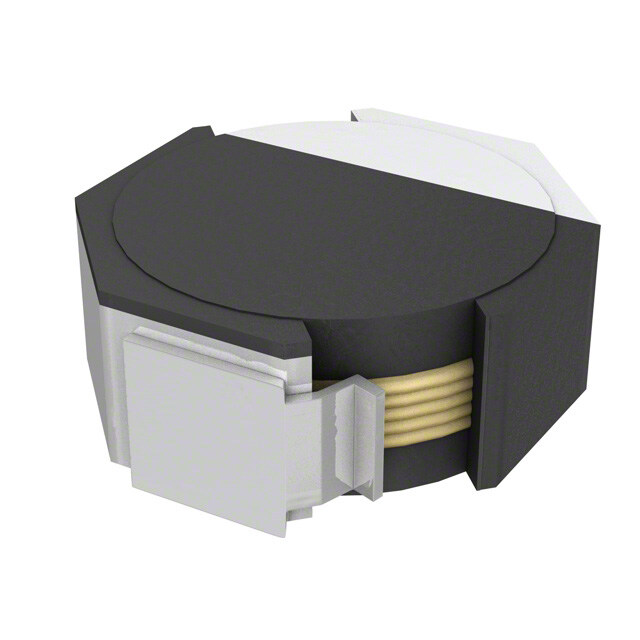
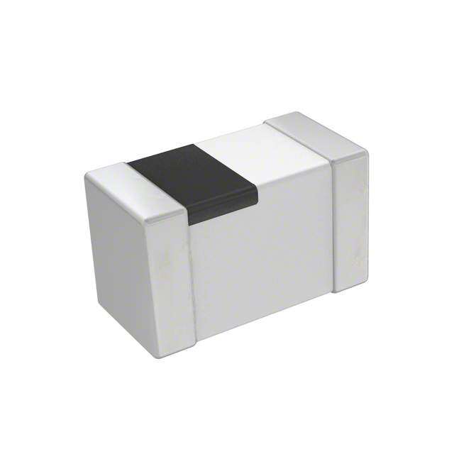
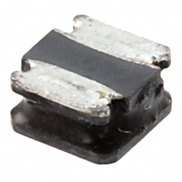
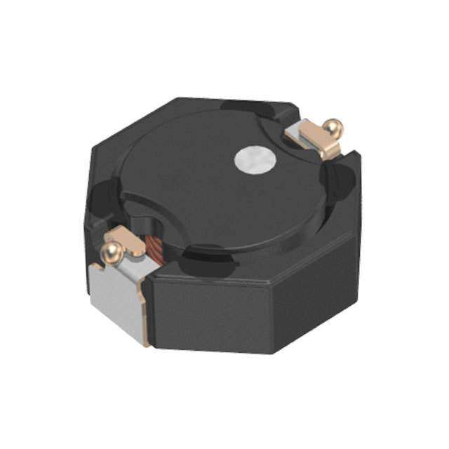
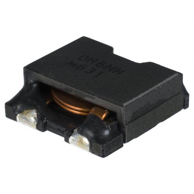
ICGOO电子元器件商城为您提供VLF4012AT-1R5M1R6由TDK设计生产,在icgoo商城现货销售,并且可以通过原厂、代理商等渠道进行代购。 VLF4012AT-1R5M1R6价格参考。TDKVLF4012AT-1R5M1R6封装/规格:固定值电感器, 1.5µH 屏蔽 绕线 电感器 1.6A 79 毫欧最大 非标准 。您可以下载VLF4012AT-1R5M1R6参考资料、Datasheet数据手册功能说明书,资料中有VLF4012AT-1R5M1R6 详细功能的应用电路图电压和使用方法及教程。
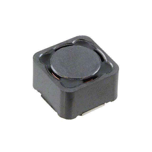
TDK Corporation的VLF4012AT-1R5M1R6是一款固定值电感器,属于功率电感器系列,广泛应用于需要高效能、小体积电感解决方案的电子设备中。

该电感器的主要应用场景包括:

1. 电源管理电路:适用于DC-DC转换器、电压调节模块(VRM)等,用于平滑电流、稳定电压,提高电源转换效率。

2. 便携式电子产品:如智能手机、平板电脑、笔记本电脑等,因其体积小巧、电感值稳定,适合高密度电路设计。

3. 汽车电子系统:用于车载电源系统、LED驱动、电池管理系统(BMS)中,具备良好的温度特性和可靠性。

4. 工业设备:包括工业自动化控制设备、电源适配器、UPS不间断电源等,适用于对稳定性和耐久性要求较高的环境。

5. 通信设备:如基站、路由器、交换机等通信基础设施中的电源模块,保障稳定供电与信号完整性。

该电感器具有低直流电阻(DCR)、高饱和电流和温升电流特性,适合高频开关电源使用,具备良好的磁屏蔽性能,减少电磁干扰(EMI)。
| 参数 | 数值 |
| 产品目录 | |
| DC电阻(DCR) | 79 毫欧最大 |
| 描述 | INDUCTOR POWER 1.5UH 1.6A SMD固定电感器 1.5uH 1.6A 4x4x1.2mm |
| 产品分类 | |
| 品牌 | TDK Corporation |
| 产品手册 | |
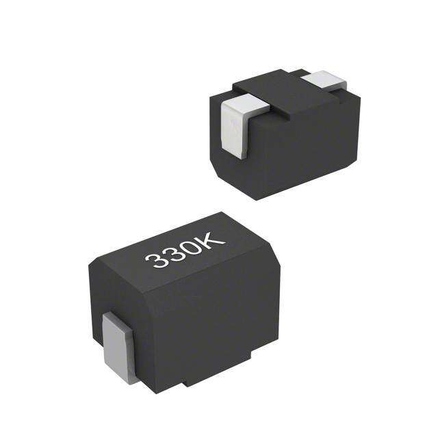
| 产品图片 |
|
| rohs | 符合RoHS无铅 / 符合限制有害物质指令(RoHS)规范要求 |
| 产品系列 | 固定电感器,TDK VLF4012AT-1R5M1R6VLF |
| 数据手册 | |
| 产品型号 | VLF4012AT-1R5M1R6 |
| 不同频率时的Q值 | - |
| 产品 | Inductors |
| 产品培训模块 | http://www.digikey.cn/PTM/IndividualPTM.page?site=cn&lang=zhs&ptm=9295 |
| 产品目录绘图 |
|
| 产品目录页面 | |
| 产品种类 | 固定电感器 |
| 供应商器件封装 | - |
| 其它名称 | 445-3232-6 |
| 包装 | Digi-Reel® |
| 商标 | TDK |
| 外壳宽度 | 3.7 mm |
| 外壳长度 | 3.5 mm |
| 外壳高度 | 1.2 mm |
| 大小/尺寸 | 0.146" 长 x 0.138" 宽 (3.70mm x 3.50mm) |
| 安装类型 | 表面贴装 |
| 容差 | ±20% |
| 封装 | Reel |
| 封装/外壳 | 非标准 |
| 屏蔽 | 屏蔽 |
| 工作温度 | -40°C ~ 105°C |
| 工作温度范围 | - 40 C to + 105 C |
| 工厂包装数量 | 1000 |
| 最大直流电流 | 1.8 A |
| 最大直流电阻 | 79 mOhms |
| 材料-磁芯 | - |
| 标准包装 | 1 |
| 测试频率 | 100 kHz |
| 电感 | 1.5µH |
| 电流-饱和值 | 1.8A |
| 端接类型 | SMD/SMT |
| 类型 | 绕线 |
| 系列 | VLF |
| 频率-测试 | 100kHz |
| 频率-自谐振 | - |
| 额定电流 | 1.6A |
| 高度-安装(最大值) | 0.047"(1.20mm) |


A%20Series%20Top.jpg)
A%20Series%20Footprint.jpg)


- 商务部:美国ITC正式对集成电路等产品启动337调查
- 曝三星4nm工艺存在良率问题 高通将骁龙8 Gen1或转产台积电
- 太阳诱电将投资9.5亿元在常州建新厂生产MLCC 预计2023年完工
- 英特尔发布欧洲新工厂建设计划 深化IDM 2.0 战略
- 台积电先进制程称霸业界 有大客户加持明年业绩稳了
- 达到5530亿美元!SIA预计今年全球半导体销售额将创下新高
- 英特尔拟将自动驾驶子公司Mobileye上市 估值或超500亿美元
- 三星加码芯片和SET,合并消费电子和移动部门,撤换高东真等 CEO
- 三星电子宣布重大人事变动 还合并消费电子和移动部门
- 海关总署:前11个月进口集成电路产品价值2.52万亿元 增长14.8%
PDF Datasheet 数据手册内容提取
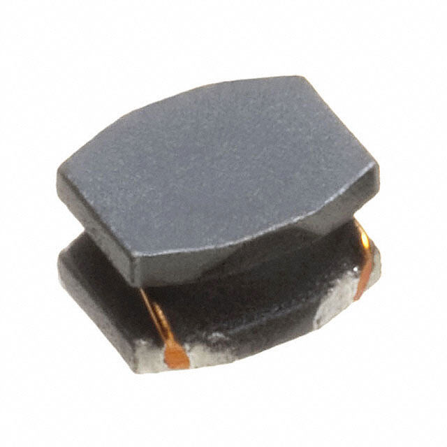
(1/2) SMD Inductors(Coils) Conformity to RoHS Directive For Power Line(Wound, Magnetic Shielded) VLF Series VLF4012A FEATURES SHAPES AND DIMENSIONS (cid:127) Mount area: 3.5×3.7mm 3 Low profile: 1.2mm max. height 4 0. R ± (cid:127) Generic use for portable DC to DC converter line. 7 3.5 (cid:127) High magnetic shield construction should actualize high resolu- 3.7±0.3 1.2max. tion for EMC protection. (Include terminal area) (cid:127) Available for automatic mounting in tape and real package. Dimensions in mm (cid:127) The products contain no lead and also support lead-free soldering. RECOMMENDED PC BOARD PATTERN (cid:127) It is a product conforming to RoHS directive. 3 1. 2.9 APPLICATIONS Power souce inductor for mobile devices such as mobile phones, 4.7 Dimensions in mm HDDs, and DSCs ELECTRICAL CHARACTERISTICS Inductance DC resistance(Ω) Rated current∗1(A) Inductance Test frequency Part No. [at 1/2 Idc1]∗2 Based on inductance Based on temperature tolerance(%) (kHz) max. typ. (µH) change Idc1 max. rise Idc2 typ. VLF4012AT-1R5M1R6 1.5 ±20 100 0.079 0.069 1.8 1.6 VLF4012AT-2R2M1R5 2.2 ±20 100 0.087 0.076 1.5 1.5 VLF4012AT-3R3M1R3 3.3 ±20 100 0.12 0.1 1.3 1.3 VLF4012AT-4R7M1R1 4.7 ±20 100 0.16 0.14 1.1 1.1 VLF4012AT-6R8MR96 6.8 ±20 100 0.23 0.2 0.96 0.97 VLF4012AT-100MR79 10 ±20 100 0.35 0.3 0.80 0.79 VLF4012AT-150MR63 15 ±20 100 0.53 0.46 0.63 0.64 VLF4012AT-220MR51 22 ±20 100 0.82 0.71 0.52 0.51 VLF4012AT-330MR39 33 ±20 100 1.4 1.2 0.44 0.39 VLF4012AT-470MR30 47 ±20 100 2.3 2.0 0.36 0.30 ∗1 Rated current: Value obtained when current flows and the temperature has risen to 40°C or when DC current flows and the nominal value of inductance has fallen by 30%, whichever is smaller. ∗2Inductance is at 1/2 Idc1 power distribution. The L vaule at 0A is higher than the guaranteed performance. (cid:127) Operating temperature range: –40 to +105°C (Including self-temperature rise) TYPICAL ELECTRICAL CHARACTERISTICS INDUCTANCE vs. DC SUPERPOSITION CHARACTERISTICS VLF4012AT-1R5M1R6 VLF4012AT-2R2M1R5 2.0 3.0 2.5 µ)H1.5 µ)H2.0 (e (e nc1.0 nc1.5 a a duct duct1.0 In0.5 In 0.5 0.0 0.0 0.0 0.2 0.4 0.6 0.8 1.0 1.2 1.4 1.6 1.8 2.0 0.0 0.2 0.4 0.6 0.8 1.0 1.2 1.4 1.6 1.8 2.0 DC current(A) DC current(A) (cid:127) Conformity to RoHS Directive: This means that, in conformity with EU Directive 2002/95/EC, lead, cadmium, mercury, hexavalent chromium, and specific bromine-based flame retardants, PBB and PBDE, have not been used, except for exempted applications. • All specifications are subject to change without notice. 002-03 / 20080629 / e531_vlf4012a.fm
(2/2) TYPICAL ELECTRICAL CHARACTERISTICS INDUCTANCE vs. DC SUPERPOSITION CHARACTERISTICS VLF4012AT-3R3M1R3 VLF4012AT-4R7M1R1 4.0 6.0 5.0 µ()InductanceH123...000 µ()InductanceH234...000 1.0 0.0 0.0 0.0 0.2 0.4 0.6 0.8 1.0 1.2 1.4 1.6 1.8 0.0 0.2 0.4 0.6 0.8 1.0 1.2 1.4 1.6 DC current(A) DC current(A) VLF4012AT-6R8MR96 VLF4012AT-100MR79 12 8.0 10 )H6.0 µ)H 8 µ(nce4.0 (ance 6 ucta duct 4 nd2.0 In I 2 0.0 0 0.0 0.2 0.4 0.6 0.8 1.0 1.2 0.0 0.1 0.2 0.3 0.4 0.5 0.6 0.7 0.8 0.9 1.0 DC current(A) DC current(A) VLF4012AT-150MR63 VLF4012AT-220MR51 20 30 25 )H15 )H µ µ20 (e (e c c n10 n15 a a ct ct du du10 In 5 In 5 0 0 0.0 0.1 0.2 0.3 0.4 0.5 0.6 0.7 0.8 0.0 0.1 0.2 0.3 0.4 0.5 0.6 0.7 DC current(A) DC current(A) VLF4012AT-330MR39 VLF4012AT-470MR30 50 60 50 40 µ()InductanceH123000 µ()InductanceH12340000 0 0 0.0 0.1 0.2 0.3 0.4 0.5 0.6 0.0 0.1 0.2 0.3 0.4 0.5 DC current(A) DC current(A) TEST CIRCUIT C=20,000µF A L=0.1H 2 1 Sample 1: LCR meter 4285A=100kHz 2: DC constant current (cid:127) All specifications are subject to change without notice. 002-03 / 20080629 / e531_vlf4012a.fm