ICGOO在线商城 > 电感器,线圈,扼流圈 > 固定值电感器 > LQG15HS5N1S02D
 Datasheet下载
- 型号: LQG15HS5N1S02D
- 制造商: Murata
- 库位|库存: xxxx|xxxx
- 要求:
| 数量阶梯 | 香港交货 | 国内含税 |
| +xxxx | $xxxx | ¥xxxx |
查看当月历史价格
查看今年历史价格
LQG15HS5N1S02D产品简介:
ICGOO电子元器件商城为您提供LQG15HS5N1S02D由Murata设计生产,在icgoo商城现货销售,并且可以通过原厂、代理商等渠道进行代购。 LQG15HS5N1S02D价格参考¥0.17-¥0.17。MurataLQG15HS5N1S02D封装/规格:固定值电感器, 5.1nH 无屏蔽 多层 电感器 650mA 200 毫欧最大 0402(1005 公制) 。您可以下载LQG15HS5N1S02D参考资料、Datasheet数据手册功能说明书,资料中有LQG15HS5N1S02D 详细功能的应用电路图电压和使用方法及教程。
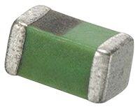
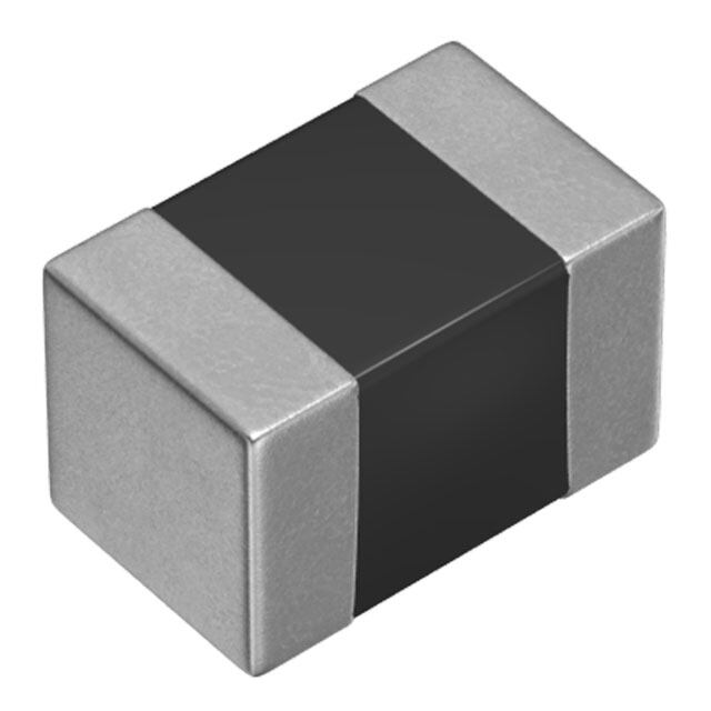
Murata Electronics North America 的 LQG15HS5N1S02D 是一款尺寸为 1.6×0.8×0.8 mm 的小型多层陶瓷固定值电感器,电感值为 5.1 nH,允许偏差 ±0.3 nH,适用于高频电路。该型号属于 LQG15HS 系列,具有低直流电阻、高 Q 值和良好的温度稳定性,特别适合用于工作频率较高的射频(RF)应用。

其主要应用场景包括智能手机、平板电脑、无线通信模块等便携式电子设备中的射频前端电路。具体可用于匹配网络、滤波电路和振荡电路中,常见于 Wi-Fi、蓝牙、GPS 和蜂窝通信(如 LTE、5G)等高频信号路径中,帮助提升信号完整性和系统效率。由于其小尺寸和高性能,非常适合空间受限的高密度贴装设计。

此外,LQG15HS5N1S02D 具有良好的抗电磁干扰能力,也适用于各类射频识别(RFID)、无线充电模块和物联网(IoT)设备中的高频信号处理环节。其可靠的性能和稳定的电气参数,使其在消费电子和工业通信产品中广泛应用。
| 参数 | 数值 |
| 产品目录 | |
| DC电阻(DCR) | 200 毫欧最大 |
| 描述 | INDUCTOR 5.1NH 300MA 0402固定电感器 5.1 NH .3% |
| 产品分类 | |
| 品牌 | Murata Electronics North America |
| 产品手册 | |
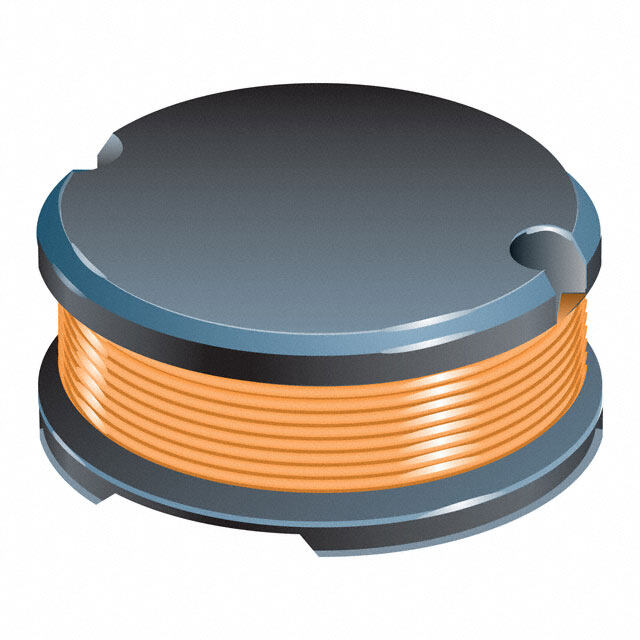
| 产品图片 |
|
| rohs | 符合RoHS无铅 / 符合限制有害物质指令(RoHS)规范要求 |
| 产品系列 | 固定电感器,Murata Electronics LQG15HS5N1S02DLQG15HS |
| 数据手册 | |
| 产品型号 | LQG15HS5N1S02D |
| Q最小值 | 8 |
| 不同频率时的Q值 | 8 @ 100MHz |
| 产品培训模块 | http://www.digikey.cn/PTM/IndividualPTM.page?site=cn&lang=zhs&ptm=5389 |
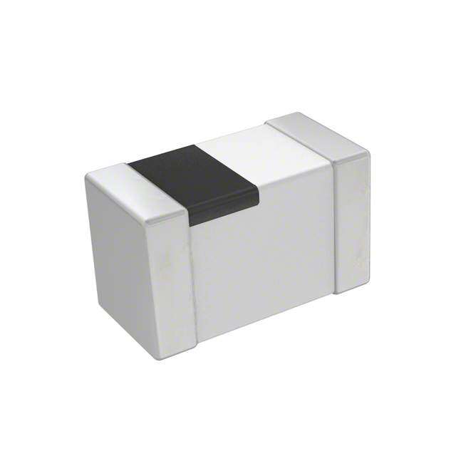
| 产品目录绘图 |
|
| 产品种类 | 固定电感器 |
| 供应商器件封装 | 0402(1005 公制) |
| 其它名称 | 490-6573-2 |
| 包装 | 带卷 (TR) |
| 商标 | Murata Electronics |
| 外壳宽度 | 0.5 mm |
| 外壳长度 | 1 mm |
| 外壳高度 | 0.5 mm |
| 大小/尺寸 | 0.039" 长 x 0.020" 宽(1.00mm x 0.50mm) |
| 安装类型 | 表面贴装 |
| 容差 | ±0.3nH |
| 封装 | Reel |
| 封装/外壳 | 0402(1005 公制) |
| 封装/箱体 | 0402 (1005 metric) |
| 屏蔽 | 无屏蔽 |
| 工作温度 | -55°C ~ 125°C |
| 工作温度范围 | - 55 C to + 125 C |
| 工厂包装数量 | 10000 |
| 最大直流电流 | 300 mA |
| 最大直流电阻 | 200 mOhms |
| 材料-磁芯 | 空气 |
| 标准包装 | 10,000 |
| 电感 | 5.1nH |
| 电流-饱和值 | - |
| 端接类型 | SMD/SMT |
| 类型 | 多层 |
| 自谐振频率 | 5300 MHz |
| 频率-测试 | 100MHz |
| 频率-自谐振 | 5.3GHz |
| 额定电流 | 300mA |
| 高度-安装(最大值) | 0.022"(0.55mm) |


- 商务部:美国ITC正式对集成电路等产品启动337调查
- 曝三星4nm工艺存在良率问题 高通将骁龙8 Gen1或转产台积电
- 太阳诱电将投资9.5亿元在常州建新厂生产MLCC 预计2023年完工
- 英特尔发布欧洲新工厂建设计划 深化IDM 2.0 战略
- 台积电先进制程称霸业界 有大客户加持明年业绩稳了
- 达到5530亿美元!SIA预计今年全球半导体销售额将创下新高
- 英特尔拟将自动驾驶子公司Mobileye上市 估值或超500亿美元
- 三星加码芯片和SET,合并消费电子和移动部门,撤换高东真等 CEO
- 三星电子宣布重大人事变动 还合并消费电子和移动部门
- 海关总署:前11个月进口集成电路产品价值2.52万亿元 增长14.8%


PDF Datasheet 数据手册内容提取
O05E.pdf Apr.28,2017 Chip Inductors (Chip Coils)
!Note (cid:129) Please read rating and !CAUTION (for storage, operating, rating, soldering, mounting and handling) in this catalog to prevent smoking and/or burning, etc. O05E.pdf (cid:129) This catalog has only typical specifications. Therefore, please approve our product specifications or transact the approval sheet for product specifications before ordering. Apr.28,2017 EU RoHS Compliant (cid:70)(cid:3)(cid:5)(cid:42)(cid:42)(cid:3)(cid:50)(cid:38)(cid:35)(cid:3)(cid:46)(cid:48)(cid:45)(cid:34)(cid:51)(cid:33)(cid:50)(cid:49)(cid:3)(cid:39)(cid:44)(cid:3)(cid:50)(cid:38)(cid:39)(cid:49)(cid:3)(cid:33)(cid:31)(cid:50)(cid:31)(cid:42)(cid:45)(cid:37)(cid:3)(cid:33)(cid:45)(cid:43)(cid:46)(cid:42)(cid:55)(cid:3) (cid:53)(cid:39)(cid:50)(cid:38)(cid:3)(cid:9)(cid:25)(cid:3)(cid:22)(cid:45)(cid:12)(cid:23)(cid:64) (cid:70)(cid:3)(cid:9)(cid:25)(cid:3)(cid:22)(cid:45)(cid:12)(cid:23)(cid:3)(cid:39)(cid:49)(cid:3)(cid:159)(cid:50)(cid:38)(cid:35)(cid:3)(cid:9)(cid:51)(cid:48)(cid:45)(cid:46)(cid:35)(cid:31)(cid:44)(cid:3)(cid:8)(cid:39)(cid:48)(cid:35)(cid:33)(cid:50)(cid:39)(cid:52)(cid:35)(cid:3) (cid:124)(cid:122)(cid:123)(cid:123)(cid:71)(cid:128)(cid:127)(cid:71)(cid:9)(cid:25)(cid:3)(cid:45)(cid:44)(cid:3)(cid:50)(cid:38)(cid:35)(cid:3)(cid:22)(cid:35)(cid:49)(cid:50)(cid:48)(cid:39)(cid:33)(cid:50)(cid:39)(cid:45)(cid:44)(cid:3)(cid:45)(cid:36)(cid:3)(cid:50)(cid:38)(cid:35)(cid:3) (cid:25)(cid:49)(cid:35)(cid:3)(cid:45)(cid:36)(cid:3)(cid:7)(cid:35)(cid:48)(cid:50)(cid:31)(cid:39)(cid:44)(cid:3)(cid:12)(cid:31)(cid:56)(cid:31)(cid:48)(cid:34)(cid:45)(cid:51)(cid:49)(cid:3)(cid:23)(cid:51)(cid:32)(cid:49)(cid:50)(cid:31)(cid:44)(cid:33)(cid:35)(cid:49)(cid:3)(cid:39)(cid:44)(cid:3) (cid:9)(cid:42)(cid:35)(cid:33)(cid:50)(cid:48)(cid:39)(cid:33)(cid:31)(cid:42)(cid:3)(cid:31)(cid:44)(cid:34)(cid:3)(cid:9)(cid:42)(cid:35)(cid:33)(cid:50)(cid:48)(cid:45)(cid:44)(cid:39)(cid:33)(cid:3)(cid:9)(cid:47)(cid:51)(cid:39)(cid:46)(cid:43)(cid:35)(cid:44)(cid:50)(cid:64)(cid:159)(cid:3) (cid:70)(cid:3)For(cid:3)(cid:43)(cid:45)(cid:48)(cid:35)(cid:3)(cid:34)(cid:35)(cid:50)(cid:31)(cid:39)(cid:42)(cid:49)(cid:65)(cid:3)(cid:46)(cid:42)(cid:35)(cid:31)(cid:49)(cid:35)(cid:3)(cid:48)(cid:35)(cid:36)(cid:35)r(cid:3)(cid:50)o(cid:3)(cid:45)ur(cid:3)(cid:53)(cid:35)(cid:32)(cid:3) (cid:46)(cid:31)(cid:37)(cid:35)(cid:65)(cid:3)(cid:159)(cid:17)(cid:51)(cid:48)(cid:31)(cid:50)(cid:31)(cid:158)(cid:49)(cid:3)(cid:5)(cid:46)(cid:46)(cid:48)(cid:45)(cid:31)(cid:33)(cid:38)(cid:3)(cid:36)(cid:45)(cid:48)(cid:3)(cid:9)(cid:25)(cid:3)(cid:22)(cid:45)(cid:12)(cid:23)(cid:159)(cid:3) (cid:72)(cid:38)(cid:50)(cid:50)(cid:46)(cid:66)(cid:71)(cid:71)(cid:53)(cid:53)(cid:53)(cid:64)(cid:43)(cid:51)(cid:48)(cid:31)(cid:50)(cid:31)(cid:64)(cid:33)(cid:45)(cid:43)(cid:71)(cid:35)(cid:44)- (cid:35)(cid:51)(cid:71)(cid:49)(cid:51)(cid:46)(cid:46)(cid:45)(cid:48)(cid:50)(cid:71)(cid:33)(cid:45)(cid:43)(cid:46)(cid:42)(cid:39)(cid:31)(cid:44)(cid:33)(cid:35)(cid:71)(cid:48)(cid:45)(cid:38)(cid:49)(cid:74)(cid:64)(cid:3) Because of the difference of measurement condition, electrical characteristics plots on this catalog may have some difference to official specification value.
!Note (cid:129) Please read rating and !CAUTION (for storage, operating, rating, soldering, mounting and handling) in this catalog to prevent smoking and/or burning, etc. O05E.pdf (cid:129) This catalog has only typical specifications. Therefore, please approve our product specifications or transact the approval sheet for product specifications before ordering. Apr.28,2017 s e n Contents er Li w o P Product specifications are as of November 2016. or s f or ct u d n Product Guide p2 I Inductors for Power Lines Part Numbering p8 s Product Detail p10 uit c !Caution/Notice p151 al Cir Soldering and Mounting p153 ner e G Packaging p158 or s f or Inductors for General Circuits uct d n I Part Numbering p164 Product Detail p165 !Caution/Notice p190 Soldering and Mounting p192 ors Packaging p196 uct d n F I R RF Inductors Part Numbering p200 Product Detail p201 !Caution/Notice p292 Soldering and Mounting p294 Packaging p298 s oducts wer Line TInOdKucOt oPrrso fdourc Ptsower Lines TOKO Pr s for Po or ct u Product Detail p302 nd I !Caution/Notice p415 Soldering and Mounting p416 Packaging p419 TOKO Products s Inductors for General Circuits cts cuit du Cir Product Detail p422 O Pro neral K e O G !Caution/Notice p427 T or Soldering and Mounting p428 ors f ct Packaging p430 du n I Please check the MURATA website (http://www.murata.com/) if you cannot find a part number in this catalog.
!Note (cid:129) Please read rating and !CAUTION (for storage, operating, rating, soldering, mounting and handling) in this catalog to prevent smoking and/or burning, etc. O05E.pdf (cid:129) This catalog has only typical specifications. Therefore, please approve our product specifications or transact the approval sheet for product specifications before ordering. Apr.28,2017 Product Guide Size Code Inductance Range (H) Rated Current (A) Series Structure in inch (in mm) 0.1n 1n 10n 100n 1μ 10μ 100μ 1m 10m 10m100m 1 10 100 LQM18FN_00 p141 0603 (1608) 1μH 10μH 50mA 150mA LQM18PN_B0 p52 0603 (1608) 1.5μH 600mA LQM18PN_C0 p53 0603 (1608) 470nH 2.2μH 700mA 850mA LQM18PN_D0 p55 0603 (1608) 2.5μH 700mA LQM18PN_DH p56 0603 (1608) 2.2μH 650mA LQM18PN_F0 p58 0603 (1608) 1μH 600mA LQM18PN_FH p59 0603 (1608) 470nH 2.2μH 700mA 1.4A LQM18PN_FR p61 0603 (1608) 220nH 4.7μH 620mA 1.25A LQM18PN_GH p63 0603 (1608) 1μH 3.3μH 1.05A LQM18PW_CH p65 0603 (1608) 1μH 2.5μH 750mA 950mA LQM21DN_00 p143 0805 (2012) 1μH 47μH 7mA 60mA LQM21FN_00 p145 0805 (2012) 1μH 47μH 7mA 220mA LQM21FN_70 p147 0805 (2012) 4.7μH 10μH 100mA 120mA LQM21FN_80 p149 0805 (2012) 4.7μH 10μH 100mA 120mA LQM21PN_C0 p67 0805 (2012) 470nH 2.2μH 600mA 1.1A LQM21PN_CA p69 0805 (2012) 2.2μH 1.05A LQM21PN_CH p71 0805 (2012) 470nH 2.2μH 1.05A 1.6A LQM21PN_EH p73 0805 (2012) 240nH 2.2μH 1.1A 2.8A LQM21PN_G0 p75 0805 (2012) 470nH 3.3μH 800mA 1.3A LQM21PN_GC p77 Multilayer Type 0805 (2012) 1μH 2.2μH 800mA 900mA LQM21PN_GH p79 0805 (2012) 470nH 4.7μH 1A 2.4A es LQM21PN_GR p81 0805 (2012) 1μH 4.7μH 800mA 1.3A n er Li LQM21PN_GS p83 0805 (2012) 2.2μH 4.7μH 750mA 950mA ow LQM2MPN_DHp102 0806 (2016) 2.2μH 1.27A P or LQM2MPN_EHp104 0806 (2016) 240nH 2.2μH 1.1A 4.1A ors f LQM2MPN_G0p106 0806 (2016) 470nH 4.7μH 1.1A 1.6A uct LQM2MPN_GHp108 0806 (2016) 160nH 2.2μH 1.3A 5A d n I LQM2HPN_CH p85 1008 (2520) 240nH 2.2μH 850mA 2.55A LQM2HPN_E0 p87 1008 (2520) 560nH 1.5A LQM2HPN_EH p88 1008 (2520) 240nH 2.2μH 1.3A 4.5A LQM2HPN_G0 p90 1008 (2520) 470nH 4.7μH 1.1A 1.8A LQM2HPN_GC p92 1008 (2520) 1μH 4.7μH 800mA 1.5A LQM2HPN_GH p94 1008 (2520) 240nH 2.2μH 1.5A 5A LQM2HPN_GS p96 1008 (2520) 2.2μH 4.7μH 1A 1.1A LQM2HPN_J0 p98 1008 (2520) 1μH 3.3μH 1A 1.5A LQM2HPN_JH p100 1008 (2520) 470nH 2.2μH 1.5A 3.2A LQM31PN_00 p110 1206 (3216) 470nH 4.7μH 700mA 1.4A LQM32PN_G0 p112 1210 (3225) 1μH 1.8A LQM32PN_GC p113 1210 (3225) 1μH 2.2A LQW15CN_00 p115 0402 (1005) 18nH 200nH 390mA 1.4A LQW15CN_10 p117 0402 (1005) 20nH 3.3μH 130mA 2.2A LQW18CN_00 p119 0603 (1608) 4.9nH 650nH 430mA 2.6A LQH2MCN_02 p14 0806 (2016) 1μH 82μH 90mA 485mA LQH2MCN_52 p16 0806 (2016) 1μH 22μH 130mA 595mA LQH2MPN_GR p18 0806 (2016) 330nH 82μH 210mA 2.2A LQH2HPN_GR p10 Wire Wound 1008 (2520) 470nH 100μH 210mA 2.9A Ferrite Core LQH2HPN_JR p12 Type 1008 (2520) 470nH 22μH 540mA 3.5A DEM2812C p388 1211 (3028) 470nH 12μH 760mA 3.1A DEM2815C p389 1211 (3028) 470nH 15μH 800mA 3.9A DEM2818C p390 1211 (3028) 470nH 12μH 1A 4.7A LQH3NPN_GR p28 1212 (3030) 470nH 250μH 140mA 2.82A LQH3NPN_JR p30 1212 (3030) 680nH 47μH 570mA 2.86A LQH3NPN_ME p32 1212 (3030) 1μH 100μH 430mA 3A 2 Continued on the following page.
!Note (cid:129) Please read rating and !CAUTION (for storage, operating, rating, soldering, mounting and handling) in this catalog to prevent smoking and/or burning, etc. O05E.pdf (cid:129) This catalog has only typical specifications. Therefore, please approve our product specifications or transact the approval sheet for product specifications before ordering. Apr.28,2017 Size Code Inductance Range (H) Rated Current (A) Series Structure in inch (in mm) 0.1n 1n 10n 100n 1μ 10μ 100μ 1m 10m 10m100m 1 10 100 LQH3NPN_MR p34 1212 (3030) 1μH 47μH 460mA 2.15A LQH31CN_03 p121 1206 (3216) 120nH 100μH 80mA 970mA LQH32CN_23 p123 1210 (3225) 1μH 560μH 60mA 800mA LQH32CN_33 p125 1210 (3225) 150nH 10μH 450mA 1.45A LQH32CN_53 p127 1210 (3225) 1μH 100μH 100mA 1A LQH32DN_23 p129 1210 (3225) 1μH 560μH 60mA 800mA LQH32DN_53 p131 1210 (3225) 1μH 100μH 100mA 1A LQH32PB_N0 p20 1210 (3225) 470nH 120μH 200mA 3.4A LQH32PB_NC p22 1210 (3225) 470nH 22μH 650mA 4.4A LQH32PN_N0 p24 1210 (3225) 470nH 120μH 200mA 3.4A LQH32PN_NC p26 1210 (3225) 470nH 22μH 650mA 4.4A DEM3512C p391 1514 (3735) 680nH 22μH 530mA 2.5A DEM3518C p392 1514 (3735) 560nH 22μH 880mA 3.4A LQH44PN_GR p40 1515 (4040) 680nH 47μH 410mA 2.5A LQH44PN_J0 p42 1515 (4040) 1μH 47μH 380mA 2A LQH44PN_P0 p44 1515 (4040) 1μH 22μH 800mA 2.95A LQH43CN_03 p133 1812 (4532) 1μH 470μH 90mA 1.08A LQH43CN_33 p135 1812 (4532) 560nH 3.9μH 1.6A 2.95A LQH43PB_26 p36 1812 (4532) 1μH 220μH 240mA 3.4A LQH43PN_26 p38 1812 (4532) 1μH 220μH 240mA 3.4A Wire Wound DEM4518C p393 Ferrite Core 1818 (4745) 1.2μH 22μH 1A 3.5A LQH5BPB_T0 p46 Type 2020 (5050) 470nH 22μH 1.4A 7.7A LQH5BPN_38 p48 2020 (5050) 1μH 150μH 650mA 7A s e Lin LQH5BPN_T0 p50 2020 (5050) 470nH 22μH 1.4A 7.7A wer D52LC p394 2020 (5252) 1.2μH 100μH 260mA 2.44A o or P D53LC HCuigrhre nt p395 2020 (5252) 1.1μH 100μH 460mA 3.87A ors f D53LC LRodwc p396 2020 (5252) 4.7μH 220μH 350mA 2.31A ct LQH55DN_03 p137 2220 (5750) 120nH 10mH 50mA 6A u d In DG6045C p399 2424 (6060) 1μH 100μH 900mA 9.5A DG6050C p401 2424 (6060) 1.2μH 100μH 1.2A 9.8A D63LCB p397 2524 (6362) 1μH 150μH 440mA 4.52A LQH66SN_03 p139 2525 (6363) 270nH 10mH 50mA 6A DS75LC p402 2929 (7373) 1μH 470μH 430mA 9.2A DEM8030C p405 3131 (8080) 1.5μH 47μH 1.3A 7.5A DEM8040C p406 3131 (8080) 1.5μH 33μH 2.4A 10A DEM8045C p407 3131 (8080) 1.5μH 47μH 2.1A 11.2A DG8040C p404 3131 (8080) 1μH 100μH 1.3A 10.4A DEM10050C p408 3939 (100100) 1.5μH 33μH 3.5A 15.3A DS104C2 p409 4040 (101101) 1.1μH 120μH 970mA 11.7A DS106C2 p411 4040 (101101) 1.2μH 330μH 690mA 12A DS126C2 p413 4949 (125125) 1.7μH 680μH 580mA 11.8A DFE201208S p302 0805 (2012) 470nH 2.2μH 1.8A 4A DFE201210S p304 0805 (2012) 470nH 2.2μH 2.1A 4.8A DFE201210U p340 0805 (2012) 240nH 2.2μH 2A 6.5A DFE201610C p306 0806 (2016) 560nH 2.2μH 1.5A 2.8A DFE201610E p336 0806 (2016) 240nH 10μH 1A 6.3A DFE201610P p328 Wire Wound 0806 (2016) 240nH 2.2μH 2A 5.4A Metal Alloy DFE201610R p320 0806 (2016) 470nH 2.2μH 1.6A 3A Core Type DFE201612C p308 0806 (2016) 470nH 2.2μH 1.6A 3.4A DFE201612E p338 0806 (2016) 330nH 4.7μH 1.8A 6.3A DFE201612P p330 0806 (2016) 240nH 2.2μH 2.1A 6.5A DFE201612R p322 0806 (2016) 470nH 2.2μH 1.7A 3.5A DFE252007F p342 1008 (2520) 470nH 4.7μH 1.2A 3.3A Continued on the following page. 3
!Note (cid:129) Please read rating and !CAUTION (for storage, operating, rating, soldering, mounting and handling) in this catalog to prevent smoking and/or burning, etc. O05E.pdf (cid:129) This catalog has only typical specifications. Therefore, please approve our product specifications or transact the approval sheet for product specifications before ordering. Apr.28,2017 Size Code Inductance Range (H) Rated Current (A) Series Structure in inch (in mm) 0.1n 1n 10n 100n 1μ 10μ 100μ 1m 10m 10m100m 1 10 100 DFE252008C p310 1008 (2520) 470nH 4.7μH 1.1A 3A DFE252010C p312 1008 (2520) 470nH 10μH 1A 3.5A DFE252010F p344 1008 (2520) 330nH 10μH 1.3A 6.8A DFE252010P p332 1008 (2520) 330nH 4.7μH 1.7A 5.7A DFE252010R p324 1008 (2520) 1μH 4.7μH 1.4A 3A DFE252012C p314 1008 (2520) 470nH 10μH 1A 3.8A DFE252012F p346 1008 (2520) 330nH 10μH 1.4A 7.6A DFE252012P p334 1008 (2520) 330nH 4.7μH 2A 6.6A DFE252012R p326 1008 (2520) 1μH 4.7μH 1.7A 3.4A DFE322510C p316 1210 (3225) 470nH 10μH 1A 3.8A DFE322512C p318 1210 (3225) 470nH 10μH 1.2A 4.7A DFE322512F p348 1210 (3225) 470nH 10μH 1.7A 6.7A FDSD0412 p350 1515 (4040) 330nH 4.7μH 2.5A 7.5A FDSD0415 p352 1515 (4040) 220nH 4.7μH 2.9A 12A FDSD0420 p354 1515 (4040) 330nH 10μH 2.5A 11A nes FDSD0512 p356 2019 (5249) 1μH 6.8μH 2.3A 6.1A er Li FDSD0515 p358 2019 (5249) 1μH 4.7μH 3.2A 7A w Po FDSD0518 p360 Wire Wound 2019 (5249) 680nH 10μH 2.7A 9A s for FDV0530 p364 MCeotrael TAylploey 2423 (6258) 110nH 4.7μH 3.6A 19.6A ctor FCUL0530 p378 2322 (5857) 360nH 470nH 16A 18A du FCUL0624 p380 2926 (7366) 220nH 470nH 17A 24A n I FCUL0630 p382 2926 (7366) 120nH 680nH 15A 32A FDUE0640 p369 3026 (7667) 150nH 420nH 22A 33A FDUE0650 p370 3026 (7667) 600nH 1μH 16A 18A FDV0618 p365 2926 (7467) 240nH 3.3μH 4.1A 14A FDV0620 p366 2926 (7467) 200nH 4.7μH 3.5A 16.2A FDVE0630 p367 2926 (7467) 160nH 10μH 3.1A 20.7A FDSD0630 p362 2726 (7066) 680nH 10μH 5.4A 17A FCUL1040 p384 4540 (115100) 180nH 420nH 34A 53A FCUL1060 p386 4640 (116100) 360nH 560nH 34A 41A FDUE1040D p371 4440 (112100) 220nH 1μH 18A 32A FDVE1040 p368 4440 (112100) 1.5μH 10μH 6.1A 14.6A FDA1055 p375 4242 (108108) 560nH 5.6μH 8A 27.7A FDUE1245 p372 4848 (123121) 500nH 2.2μH 17A 30A FDA1254 p377 5049 (126125) 680nH 8μH 9.1A 29.1A FDUE1260 p373 5650 (143127) 450nH 42A LQB15NN_10 p165 0402 (1005) 220nH 560nH 300mA 380mA LQB18NN_10 p167 0603 (1608) 220nH 560nH 300mA 450mA Multilayer Type LQM18NN_00 p183 0603 (1608) 47nH 2.2μH 15mA 50mA LQM21NN_10 p185 0805 (2012) 100nH 4.7μH 30mA 250mA uits LLB2520 p422 1008 (2520) 1μH 47μH 100mA 480mA Circ LLM2520 p423 1008 (2520) 100nH 220μH 44mA 570mA eral LQH31HN_03 p169 1206 (3216) 54nH 880nH 180mA 920mA n Ge LQH31MN_03 p171 1206 (3216) 150nH 100μH 45mA 250mA s for LLM3225 p425 Wire Wound 1210 (3225) 100nH 1mH 19mA 600mA ctor LQH32MN_23 p173 Ferrite Core 1210 (3225) 1μH 560μH 40mA 445mA du LQH44NN_03 p181 Type 1515 (4040) 510nH 470μH 145mA 4.5A n I LQH43MN_03 p175 1812 (4532) 1μH 1.5mH 40mA 500mA LQH43NN_03 p178 1812 (4532) 1μH 2.4mH 25mA 500mA LQW04CA_00 p187 03019 (0805) 60nH 510nH 200mA 620mA LQW15CA_00 p188 0402 (1005) 22nH 2μH 130mA 1.3A Continued on the following page. 4
!Note (cid:129) Please read rating and !CAUTION (for storage, operating, rating, soldering, mounting and handling) in this catalog to prevent smoking and/or burning, etc. O05E.pdf (cid:129) This catalog has only typical specifications. Therefore, please approve our product specifications or transact the approval sheet for product specifications before ordering. Apr.28,2017 Size Code Inductance Range (H) Rated Current (A) Series Structure in inch (in mm) 0.1n 1n 10n 100n 1μ 10μ 100μ 1m 10m 10m100m 1 10 100 LQG15HN_02 p201 0402 (1005) 1nH 120nH 150mA 1A LQG15HS_02 p204 Multilayer Type 0402 (1005) 1nH 270nH 110mA 1A LQG18HN_00 p208 0603 (1608) 1.2nH 100nH 350mA 1.1A p289 Wire Wound LQW21HN_00 Ferrite Core 0805 (2012) 470nH 2.2μH 75mA 160mA Type LQP02HQ_02 p210 01005 (0402) 0.2nH 56nH 100mA 1A LQP02TN_02 p214 01005 (0402) 0.2nH 39nH 90mA 320mA LQP02TQ_02 p218 01005 (0402) 0.2nH 22nH 120mA 990mA LQP03HQ_02 p221 0201 (0603) 0.6nH 150nH 80mA 1.1A LQP03PN_02 p225 0201 (0603) 2.2nH 4.7nH 900mA 1.4A Film Type LQP03TG_02 p227 0201 (0603) 0.1nH 120nH 80mA 850mA LQP03TN_02 p231 0201 (0603) 0.6nH 270nH 60mA 850mA LQP03TQ_02 p235 0201 (0603) 0.6nH 13nH 250mA 1A LQP15MN_02 p238 0402 (1005) 1nH 33nH 60mA 400mA ors LQP18MN_02 p240 0603 (1608) 1.3nH 100nH 50mA 300mA duct LQW03AW_00p242 0201 (0603) 1nH 15.5nH 230mA 900mA n F I LQW04AN_00p244 03015 (0804) 0.8nH 33nH 140mA 1.8A R LQW04AN_10p249 03015 (0804) 36nH 56nH 180mA 200mA LQW15AN_00p250 0402 (1005) 1.5nH 120nH 110mA 1A LQW15AN_10p256 0402 (1005) 1.3nH 8.4nH 640mA 1.2A LQW15AN_80p258 0402 (1005) 1.3nH 75nH 320mA 3.15A LQW18AN_00p265 0603 (1608) 2.2nH 470nH 75mA 850mA LQW18AN_10p268 Wire Wound 0603 (1608) 2.2nH 33nH 550mA 1.4A Non-Magnetic LQW18AN_80p270 Core Type 0603 (1608) 2.2nH 390nH 190mA 3.2A LQW18AS_00 p275 0603 (1608) 1.6nH 390nH 100mA 700mA LQW2BAN_00p278 0805 (2015) 3.2nH 200nH 750mA 3.8A LQW2BAS_00 p281 0805 (2015) 2.8nH 820nH 180mA 800mA LQW2BHN_03p283 0805 (2015) 3.3nH 470nH 160mA 1.32A LQW2BHN_13p285 0805 (2015) 2.7nH 27nH 900mA 1.9A LQW2UAS_00 p286 1008 (2520) 12nH 4.7μH 260mA 1A LQW31HN_03p290 1206 (3216) 8.8nH 100nH 230mA 750mA 5
!Note (cid:129) Please read rating and !CAUTION (for storage, operating, rating, soldering, mounting and handling) in this catalog to prevent smoking and/or burning, etc. O05E.pdf (cid:129) This catalog has only typical specifications. Therefore, please approve our product specifications or transact the approval sheet for product specifications before ordering. Apr.28,2017 MEMO 6
!Note (cid:129) Please read rating and !CAUTION (for storage, operating, rating, soldering, mounting and handling) in this catalog to prevent smoking and/or burning, etc. O05E.pdf (cid:129) This catalog has only typical specifications. Therefore, please approve our product specifications or transact the approval sheet for product specifications before ordering. Apr.28,2017 s e n Li er w o P or s f or ct u d n I s uit c Cir al Inductors for Power Lines er n e G or s f Part Numbering p8 ctor u d Product Detail p10 In !Caution/Notice p151 Soldering and Mounting p153 Packaging p158 s or ct u d n F I R s oducts wer Line Pr o TOKO s for P or ct u d n I s cts cuit du Cir O Pro neral K e O G T or s f or ct u d n I 7
!Note (cid:129) Please read rating and !CAUTION (for storage, operating, rating, soldering, mounting and handling) in this catalog to prevent smoking and/or burning, etc. O05E.pdf (cid:129) This catalog has only typical specifications. Therefore, please approve our product specifications or transact the approval sheet for product specifications before ordering. Apr.28,2017 o Part Numbering s e n er Li Inductors for Power Lines w Po (Part Number) LQ M 21 P N R54 M G 0 D s for 1 2 3 4 5 6 7 8 9 : or ct 1Product ID 6Inductance u d In Product ID Expressed by three-digit alphanumerics. The unit is micro-henry LQ Chip Inductors (Chip Coils) (μH). The first and second figures are significant digits, and the third figure expresses the number of zeros that follow the two figures. If there is a decimal point, it is expressed by the capital 2Structure letter "R." In this case, all figures are significant digits. If inductance is less than 0.1μH, the inductance code is expressed by a Code Structure combination of two figures and the capital letter "N," and the unit s H of inductance is nano-henry (nH). The capital letter "N" indicates cuit W Wire Wound Type (Ferrite Core) the unit of "nH," and also expresses a decimal point. In this case, all eral Cir M Multilayer Type (Ferrite Core) fivagluureess aarree sspigenciifificeadn uts diniggi ttsh. rFeoer dthesoisgen aptreodd udcigtsit ws, hthoesese in vdaulucetasn mcea y n be indicated using the closest two digits instead. e G 3Dimensions (LxW) s for Code Nominal Dimensions (LxW)Size Code (in inch) 7Inductance Tolerance or ct 1155 1.0x0.5mm 0402 Code Inductance Tolerance u d In 1188 1.6x0.8mm 0603 D ±0.5nH 2211 2.0x1.25mm 0805 J ±5% 23M1 2.0x1.6mm 0806 K ±10% 23H2 2.5x2.0mm 1008 M ±20% 34N3 3.0x3.0mm 1212 N ±30% s ctor 3414 3.2x1.6mm 1206 ndu 32 3.2x2.5mm 1210 8Features (Except for LQHppP/LQMppP) RF I 43 4.5x3.2mm 1812 Code Features Series 44 4.0x4.0mm 1515 0 Standard Type LQM/LQH*1 /LQW 5B 5.0x5.0mm 2020 1 Low DC Resistance LQW 55 5.7x5.0mm 2220 2 Standard Type LQH32C/32D 66 6.3x6.3mm 2525 3 Low DC Resistance LQH32C/43CN 5 Low Profile Type LQH2MC/32C/32D 4Applications and Characteristics 7 Large Current Type Code Series Applications and Characteristics 8 Low DC Resistance LQM21F ducts nes DF LQM forf oCrh oCkhe o(Lkoew -(cDuCrre Pnto DwCe Pro Swuepr pSulipepsli)es) *1 Except for LQH32 S/eLraiersge Current Type O Pro wer Li D LQH for Choke OK Po S for Choke (Magnetically Shielded Type) 8Thickness T s for C LQH/LQW for Choke (Coating Type) (LQHppP/LQMppP(cid:3)(cid:19)(cid:44)(cid:42)(cid:55)(cid:3)(cid:70)(cid:3)(cid:9)(cid:54)(cid:33)(cid:35)(cid:46)(cid:50)(cid:3)(cid:36)(cid:45)(cid:48)(cid:3)LQH43P/LQH5BPN_38) ctor P LQM/LQH for Power Line Code Nominal Dimensions (T) u nd B 0.35mm I 5Category C 0.5mm Code Category D 0.6mm N Standard Type E 0.7mm B F 0.8mm Special Feature Classification s W 0 0.85mm duct uits G 0.9mm o c Pr Cir J 1.1mm OKO eral M 1.4mm T n Ge N 1.55mm s for P 1.65mm ctor T 2.0mm u nd Continued on the following page. I 8
!Note (cid:129) Please read rating and !CAUTION (for storage, operating, rating, soldering, mounting and handling) in this catalog to prevent smoking and/or burning, etc. O05E.pdf (cid:129) This catalog has only typical specifications. Therefore, please approve our product specifications or transact the approval sheet for product specifications before ordering. Apr.28,2017 Continued from the preceding page. s e n Li 9Electrode (Except for LQHppP/LQMppP) wer o (cid:70)(cid:16)(cid:35)(cid:31)(cid:34)(cid:3)(cid:72)(cid:20)(cid:32)(cid:74)(cid:3)(cid:10)(cid:48)(cid:35)(cid:35) or P Code Electrode Series ors f 0 LQM/LQW ct u Sn d 2 LQH2MC n I 3 LF Solder LQH (Except for LQH2MC) 9Specification (LQHppP/LQMppP(cid:3)(cid:19)(cid:44)(cid:42)(cid:55)(cid:3)(cid:70)(cid:3)(cid:9)(cid:54)(cid:33)(cid:35)(cid:46)(cid:50)(cid:3)(cid:36)(cid:45)(cid:48)(cid:3)LQH43P/LQH5BPN_38) Code Specification s 0/S Standard Type cuit C Good Bias Current Characteristics Type al Cir er H/A/E High Spec Type (Low DC Resistance; en Good Bias Current Characteristics Type) or G R Low DC Resistance Type s f or ct u 89Thickness (LQH43P/LQH5BPN_38 Only) nd I Code Dimensions (T) 26 2.6mm 38 4.0mm max. s :Packaging or ct u Code Packaging Series nd K LQH*1 /LQM21*2 RF I Embossed Taping (ø330mm Reel) F LQH3NP_MR L LQH*5/LQM18P/LQM21*2 /LQM31P/LQM32P/LQM2HP/LQM2MP Embossed Taping (ø180mm Reel) E LQH3NP_MR B Bulk LQH2MC/LQM/LQW J Paper Taping (ø330mm Reel) LQM18/LQM21*3 D Paper Taping (ø180mm Reel) LQM18/LQM21*4 /LQW *1 Except for LQH2MC/LQH2HP_G0/LQH3NP/LQH43C *2 LQM21D(22 - 47μH)/LQM21F(4.7 - 47μH) s ***345 LLEQQxcMMe22pt11 DDfo((r11 L..00Q --H 11300NμμPHH_))M//LLRQQMM2211FF((11..00 -- 22..22μμHH))/LQM21P Products ower Line TOKO s for P or ct u d n I s cts cuit du Cir O Pro neral K e O G T or s f or ct u d n I 9
!Note • Please read rating and !CAUTION (for storage, operating, rating, soldering, mounting and handling) in this catalog to prevent smoking and/or burning, etc. O05E.pdf • This catalog has only typical specifications. Therefore, please approve our product specifications or transact the approval sheet for product specifications before ordering. Apr.28,2017 Inductors for Power Lines s e Lin LQH2HPN_GR Series er 1008 (2520) inch (mm) w o P or s f or ct u d n Appearance/Dimensions Packaging I Minimum Code Packaging Quantity L ø180mm Embossed Taping 3000 1 uits 2.5±0.2 0.9±0. 2.0±0.2 c Cir al er n Ge 0.2 s for 2.0± or 0.62±0.2 0.62±0.2 ct u d n (in mm) I Rated Value (p: packaging code) Inductance Operating temp. range Operating temp. range Part Number Inductance Rated Current (Isat)* Rated Current (Itemp)* DC Resistance S.R.F.* (min.) Remark s Test Frequency (Self-temp. rise included) (Self-temp. rise not included) or ct 2520mA(Ambient temp.85°C) ndu LQH2HPNR47MGRp 0.47μH ±20% 1MHz 2900mA 1470mA(Ambient temp.105°C) 0.045Ω±20% 120MHz -40 to 125°C -40 to 105°C *1 F I R 2330mA(Ambient temp.85°C) LQH2HPNR68MGRp 0.68μH ±20% 1MHz 2430mA 0.055Ω±20% 110MHz -40 to 125°C -40 to 105°C *1 1350mA(Ambient temp.105°C) 2100mA(Ambient temp.85°C) LQH2HPN1R0MGRp 1.0μH ±20% 1MHz 2130mA 0.068Ω±20% 100MHz -40 to 125°C -40 to 105°C *1 1200mA(Ambient temp.105°C) 1850mA(Ambient temp.85°C) LQH2HPN1R5MGRp 1.5μH ±20% 1MHz 1700mA 0.087Ω±20% 90MHz -40 to 125°C -40 to 105°C *1 1110mA(Ambient temp.105°C) 1470mA(Ambient temp.85°C) LQH2HPN2R2MGRp 2.2μH ±20% 1MHz 1550mA 0.134Ω±20% 80MHz -40 to 125°C -40 to 105°C *1 850mA(Ambient temp.105°C) s uct es LQH2HPN3R3MGRp 3.3μH ±20% 1MHz 1230mA 1100mA(Ambient temp.85°C) 0.225Ω±20% 70MHz -40 to 125°C -40 to 105°C *1 O Prod wer Lin 616000m0mAA(A(Ammbibeinetn tt etmemp.p1.0855°°CC)) K o LQH2HPN4R7MGRp 4.7μH ±20% 1MHz 1090mA 0.300Ω±20% 50MHz -40 to 125°C -40 to 105°C *1 O P 570mA(Ambient temp.105°C) T or s f 860mA(Ambient temp.85°C) or LQH2HPN6R8MGRp 6.8μH ±20% 1MHz 830mA 0.395Ω±20% 40MHz -40 to 125°C -40 to 105°C *1 ct 490mA(Ambient temp.105°C) u d In LQH2HPN100MGRp 10μH ±20% 1MHz 700mA 710mA(Ambient temp.85°C) 0.560Ω±20% 30MHz -40 to 125°C -40 to 105°C *1 430mA(Ambient temp.105°C) 560mA(Ambient temp.85°C) LQH2HPN150MGRp 15μH ±20% 1MHz 570mA 0.925Ω±20% 20MHz -40 to 125°C -40 to 105°C *1 310mA(Ambient temp.105°C) 430mA(Ambient temp.85°C) LQH2HPN220MGRp 22μH ±20% 1MHz 460mA 1.360Ω±20% 15MHz -40 to 125°C -40 to 105°C *1 s 250mA(Ambient temp.105°C) duct uits LQH2HPN101MGRp 100μH ±20% 1MHz 210mA 150mA(Ambient temp.85°C) 5.9Ω±20% 5MHz -40 to 105°C -40 to 85°C *2 o c Pr Cir OKO eral CFolar srse folof wM asgonldeetricin Sgh oienlldy: Magnetic Resin T n e *Isat: Rated Current based on Inductance change G or *Itemp: Rated Current based on Temperature rise s f *S.R.F.: Self-Resonant Frequency ctor *1: When rated current is applied to the products, inductance will be within ±30% of initial inductance value range. Keep the temperature (ambient temperature plus self-generation of heat) du under 125°C. When rated current is applied to the products, the temperature rise caused by self-generated heat shall be limited to 40°C (at the rated current under 85°C) or 20°C (at the n I rated current under 105°C). *2: When rated current is applied to the products, inductance will be within ±30% of initial inductance value range. Keep the temperature (ambient temperature plus self-generation of heat) under 105°C. When rated current is applied to the products, the temperature rise caused by self-generated heat shall be limited to 20°C. Continued on the following page. 10
!Note (cid:129) Please read rating and !CAUTION (for storage, operating, rating, soldering, mounting and handling) in this catalog to prevent smoking and/or burning, etc. O05E.pdf (cid:129) This catalog has only typical specifications. Therefore, please approve our product specifications or transact the approval sheet for product specifications before ordering. Apr.28,2017 Continued from the preceding page. Inductance-Frequency Characteristics (Typ.) Inductance-Current Characteristics (Typ.) es n Li er w o P or s f or ct u d n I s uit c Cir al er n e G or s f or ct u d n Temperature Rise Characteristics (Typ.) I s or ct u d n F I R s oducts wer Line Pr o TOKO s for P or ct u d n I s cts cuit du Cir O Pro neral K e O G T or s f or ct u d n I 11
!Note • Please read rating and !CAUTION (for storage, operating, rating, soldering, mounting and handling) in this catalog to prevent smoking and/or burning, etc. O05E.pdf • This catalog has only typical specifications. Therefore, please approve our product specifications or transact the approval sheet for product specifications before ordering. Apr.28,2017 Inductors for Power Lines s e Lin LQH2HPN_JR Series er 1008 (2520) inch (mm) w o P or s f or ct u d n Appearance/Dimensions Packaging I Minimum Code Packaging Quantity L ø180mm Embossed Taping 2000 1 uits 2.5±0.2 1.1±0. 2.0±0.2 Circ A B al er n e G or s f or 0.65±0.2 0.65±0.2 A: 2.75 max. ct B: 2.25 max. u d n (in mm) I Rated Value (p: packaging code) Inductance Part Number Inductance Rated Current (Isat)* Rated Current (Itemp)* DC Resistance S.R.F.* (min.) s Test Frequency or ct 2750mA(Ambient temp.85°C) ndu LQH2HPNR47NJRp 0.47μH ±30% 1MHz 3500mA 1650mA(Ambient temp.105°C) 0.031Ω±20% 190MHz F I R 2400mA(Ambient temp.85°C) LQH2HPN1R0NJRp 1.0μH ±30% 1MHz 2600mA 0.048Ω±20% 120MHz 1440mA(Ambient temp.105°C) 2070mA(Ambient temp.85°C) LQH2HPN1R2NJRp 1.2μH ±30% 1MHz 2450mA 0.055Ω±20% 100MHz 1240mA(Ambient temp.105°C) 1810mA(Ambient temp.85°C) LQH2HPN1R5NJRp 1.5μH ±30% 1MHz 2200mA 0.075Ω±20% 95MHz 1080mA(Ambient temp.105°C) 1650mA(Ambient temp.85°C) LQH2HPN2R2MJRp 2.2μH ±20% 1MHz 1700mA 0.092Ω±20% 50MHz 990mA(Ambient temp.105°C) s uct es LQH2HPN3R3MJRp 3.3μH ±20% 1MHz 1450mA 1420mA(Ambient temp.85°C) 0.13Ω±20% 45MHz O Prod wer Lin 815209m0mAA(A(Ammbibeinetn tt etmemp.p1.0855°°CC)) K o LQH2HPN4R7MJRp 4.7μH ±20% 1MHz 1230mA 0.17Ω±20% 40MHz O P 770mA(Ambient temp.105°C) T or s f 1000mA(Ambient temp.85°C) or LQH2HPN6R8MJRp 6.8μH ±20% 1MHz 1050mA 0.26Ω±20% 35MHz ct 600mA(Ambient temp.105°C) u d In LQH2HPN100MJRp 10μH ±20% 1MHz 830mA 830mA(Ambient temp.85°C) 0.38Ω±20% 30MHz 490mA(Ambient temp.105°C) 710mA(Ambient temp.85°C) LQH2HPN150MJRp 15μH ±20% 1MHz 690mA 0.55Ω±20% 20MHz 420mA(Ambient temp.105°C) 540mA(Ambient temp.85°C) LQH2HPN220MJRp 22μH ±20% 1MHz 530mA 0.84Ω±20% 20MHz s 320mA(Ambient temp.105°C) oduct cuits Operating temp. range (Self-temp. rise included): -40 to 125°C OKO Pr eral Cir OClpaesrsa otifn Mg ategmnept.i cra Snhgiee l(dS: eMlfa-tgenmetpi.c r Risees ninot included): -40 to 105°C T en For reflow soldering only G or *Isat: Rated Current based on Inductance change s f *Itemp: Rated Current based on Temperature rise or *S.R.F.: Self-Resonant Frequency uct When rated current is applied to the products, inductance will be within ±30% of intial inductance value range. Keep the temperature (ambient temperature plus self-generation of heat) d n under 125°C. When rated current is applied to the products, the temperature rise caused by self-generated heat shall be limited to 40°C max (ambient temperature 85°C). When rated I current is applied to the products, the temperature rise caused by self-generated heat shall be limited to 20°C max (ambient temperature 85-105°C). Continued on the following page. 12
!Note (cid:129) Please read rating and !CAUTION (for storage, operating, rating, soldering, mounting and handling) in this catalog to prevent smoking and/or burning, etc. O05E.pdf (cid:129) This catalog has only typical specifications. Therefore, please approve our product specifications or transact the approval sheet for product specifications before ordering. Apr.28,2017 Continued from the preceding page. Inductance-Frequency Characteristics (Typ.) Inductance-Current Characteristics (Typ.) es n Li er w o P or s f or ct u d n I s uit c Cir al er n e G or s f or ct u d n Temperature Rise Characteristics (Typ.) I s or ct u d n F I R s oducts wer Line Pr o TOKO s for P or ct u d n I s cts cuit du Cir O Pro neral K e O G T or s f or ct u d n I 13
!Note • Please read rating and !CAUTION (for storage, operating, rating, soldering, mounting and handling) in this catalog to prevent smoking and/or burning, etc. O05E.pdf • This catalog has only typical specifications. Therefore, please approve our product specifications or transact the approval sheet for product specifications before ordering. Apr.28,2017 Inductors for Power Lines s e Lin LQH2MCN_02 Series er 0806 (2016) inch (mm) w o P or s f or ct u d n Appearance/Dimensions Packaging I Minimum Code Packaging Quantity 5 0.0 L ø180mm Embossed Taping 3000 0± 0.9 B Packing in Bulk 100 s 2.0±0.2 1.6±0.2 uit c Cir al er n e G or s f or 0.6±0.2 0.6±0.2 ct u d n (in mm) I Rated Value (p: packaging code) Inductance Part Number Inductance Rated Current DC Resistance S.R.F.* (min.) s Test Frequency or ct LQH2MCN1R0M02p 1.0μH ±20% 1MHz 485mA 0.30Ω±30% 100MHz u nd LQH2MCN1R5M02p 1.5μH ±20% 1MHz 445mA 0.40Ω±30% 95MHz F I R LQH2MCN2R2M02p 2.2μH ±20% 1MHz 425mA 0.48Ω±30% 70MHz LQH2MCN3R3M02p 3.3μH ±20% 1MHz 375mA 0.60Ω±30% 65MHz LQH2MCN4R7M02p 4.7μH ±20% 1MHz 300mA 0.8Ω±30% 60MHz LQH2MCN5R6M02p 5.6μH ±20% 1MHz 280mA 0.9Ω±30% 60MHz LQH2MCN6R8M02p 6.8μH ±20% 1MHz 255mA 1.0Ω±30% 55MHz LQH2MCN8R2M02p 8.2μH ±20% 1MHz 235mA 1.1Ω±30% 50MHz LQH2MCN100K02p 10μH ±10% 1MHz 225mA 1.2Ω±30% 48MHz LQH2MCN120K02p 12μH ±10% 1MHz 210mA 1.4Ω±30% 44MHz ucts es LQH2MCN150K02p 15μH ±10% 1MHz 200mA 1.6Ω±30% 40MHz O Prod wer Lin LLQQHH22MMCCNN128200KK0022pp 1282μμHH ±±1100%% 11MMHHzz 119805mmAA 12..81ΩΩ±±3300%% 3350MMHHzz K o TO or P LQH2MCN270K02p 27μH ±10% 1MHz 180mA 2.5Ω±30% 30MHz s f LQH2MCN330K02p 33μH ±10% 1MHz 160mA 2.8Ω±30% 28MHz or ct LQH2MCN390K02p 39μH ±10% 1MHz 125mA 4.4Ω±30% 24MHz u d n LQH2MCN470K02p 47μH ±10% 1MHz 120mA 5.1Ω±30% 18MHz I LQH2MCN560K02p 56μH ±10% 1MHz 110mA 5.7Ω±30% 17MHz LQH2MCN680K02p 68μH ±10% 1MHz 100mA 6.6Ω±30% 14MHz LQH2MCN820K02p 82μH ±10% 1MHz 90mA 7.5Ω±30% 14MHz Operating temp. range (Self-temp. rise not included): -40 to 85°C s Class of Magnetic Shield: No Shield duct uits For reflow soldering only Pro Circ *S.R.F.: Self-Resonant Frequency OKO eral Wgehneenra rtaetde dh ecautr rsehnatl li sb aep lipmliietde dt ot ot h4e0 p°Cro mduacxt.s, inductance will be within ±10% of initial inductance value. When rated current is applied to the products, the temperature rise caused by self- T n Ge Continued on the following page. or s f or ct u d n I 14
!Note (cid:129) Please read rating and !CAUTION (for storage, operating, rating, soldering, mounting and handling) in this catalog to prevent smoking and/or burning, etc. O05E.pdf (cid:129) This catalog has only typical specifications. Therefore, please approve our product specifications or transact the approval sheet for product specifications before ordering. Apr.28,2017 Continued from the preceding page. Inductance-Frequency Characteristics (Typ.) Inductance-Current Characteristics (Typ.) es n Li er w o P or s f or ct u d n I s uit c Cir al er n e G or s f or ct u d n Temperature Rise Characteristics (Typ.) I s or ct u d n F I R s oducts wer Line Pr o TOKO s for P or ct u d n I s cts cuit du Cir O Pro neral K e O G T or s f or ct u d n I 15
!Note • Please read rating and !CAUTION (for storage, operating, rating, soldering, mounting and handling) in this catalog to prevent smoking and/or burning, etc. O05E.pdf • This catalog has only typical specifications. Therefore, please approve our product specifications or transact the approval sheet for product specifications before ordering. Apr.28,2017 Inductors for Power Lines s e Lin LQH2MCN_52 Series er 0806 (2016) inch (mm) w o P or s f or ct u d n Appearance/Dimensions Packaging I Minimum 5 Code Packaging 0.0 Quantity 0.65± min. L ø180mm Embossed Taping 3000 1 0. B Packing in Bulk 100 uits 2.0±0.2 1.6±0.2 c Cir al er or Gen 1.0±0.2 s f or ct 0.6±0.2 0.6±0.2 u d n (in mm) I Rated Value (p: packaging code) Inductance Part Number Inductance Rated Current DC Resistance S.R.F.* (min.) s Test Frequency or ct LQH2MCN1R0M52p 1.0μH ±20% 1MHz 595mA 0.25Ω±30% 215MHz u nd LQH2MCN1R5M52p 1.5μH ±20% 1MHz 540mA 0.33Ω±30% 165MHz F I R LQH2MCN2R2M52p 2.2μH ±20% 1MHz 500mA 0.42Ω±30% 125MHz LQH2MCN3R3M52p 3.3μH ±20% 1MHz 360mA 0.74Ω±30% 110MHz LQH2MCN4R7M52p 4.7μH ±20% 1MHz 335mA 0.91Ω±30% 90MHz LQH2MCN6R8M52p 6.8μH ±20% 1MHz 285mA 1.23Ω±30% 65MHz LQH2MCN100M52p 10μH ±20% 1MHz 200mA 2.27Ω±30% 60MHz LQH2MCN120M52p 12μH ±20% 1MHz 170mA 2.4Ω±30% 30MHz LQH2MCN150M52p 15μH ±20% 1MHz 150mA 3.5Ω±30% 30MHz LQH2MCN180M52p 18μH ±20% 1MHz 140mA 4.0Ω±30% 30MHz ucts es LQH2MCN220M52p 22μH ±20% 1MHz 130mA 5.5Ω±30% 30MHz d n O Pro wer Li OClpaesrsa otifn Mg ategmnept.i cra Snhgiee l(dS: eNlfo- tSehmiepl.d rise not included): -40 to 85°C OK Po For reflow soldering only T or *S.R.F.: Self-Resonant Frequency s f When rated current is applied to the products, inductance will be within ±10% of initial inductance value. When rated current is applied to the products, the temperature rise caused by self- or ct generated heat shall be limited to 40°C max. u d n I Inductance-Frequency Characteristics (Typ.) Inductance-Current Characteristics (Typ.) s duct uits o c Pr Cir OKO eral T n e G or s f or ct u d n I Continued on the following page. 16
!Note (cid:129) Please read rating and !CAUTION (for storage, operating, rating, soldering, mounting and handling) in this catalog to prevent smoking and/or burning, etc. O05E.pdf (cid:129) This catalog has only typical specifications. Therefore, please approve our product specifications or transact the approval sheet for product specifications before ordering. Apr.28,2017 Continued from the preceding page. Temperature Rise Characteristics (Typ.) es n Li er w o P or s f or ct u d n I s uit c Cir al er n e G or s f or ct u d n I s or ct u d n F I R s oducts wer Line Pr o TOKO s for P or ct u d n I s cts cuit du Cir O Pro neral K e O G T or s f or ct u d n I 17
!Note • Please read rating and !CAUTION (for storage, operating, rating, soldering, mounting and handling) in this catalog to prevent smoking and/or burning, etc. O05E.pdf • This catalog has only typical specifications. Therefore, please approve our product specifications or transact the approval sheet for product specifications before ordering. Apr.28,2017 Inductors for Power Lines s e Lin LQH2MPN_GR Series er 0806 (2016) inch (mm) w o P or s f or ct u d n Appearance/Dimensions Packaging I Minimum Code Packaging Quantity L ø180mm Embossed Taping 3000 5 0 0. 2.0±0.1 0± uits 0.9 c Cir al ner 1.6±0.1 e G ors for 1.0±0.2 ct u nd 0.65±0.2 0.65±0.2 (in mm) I Rated Value (p: packaging code) Inductance Part Number Inductance Rated Current (Isat)* Rated Current (Itemp)* DC Resistance S.R.F.* (min.) s Test Frequency or ct 1130mA(Ambient temp.85°C) ndu LQH2MPNR33NGRp 0.33μH ±30% 1MHz 2200mA 670mA(Ambient temp.105°C) 0.15Ω±20% 130MHz F I R 1060mA(Ambient temp.85°C) LQH2MPNR47NGRp 0.47μH ±30% 1MHz 1950mA 0.18Ω±20% 120MHz 630mA(Ambient temp.105°C) 900mA(Ambient temp.85°C) LQH2MPN1R0NGRp 1.0μH ±30% 1MHz 1550mA 0.25Ω±20% 100MHz 540mA(Ambient temp.105°C) 790mA(Ambient temp.85°C) LQH2MPN1R5NGRp 1.5μH ±30% 1MHz 1330mA 0.32Ω±20% 60MHz 470mA(Ambient temp.105°C) 680mA(Ambient temp.85°C) LQH2MPN2R2MGRp 2.2μH ±20% 1MHz 1180mA 0.39Ω±20% 50MHz 400mA(Ambient temp.105°C) s uct es LQH2MPN3R3MGRp 3.3μH ±20% 1MHz 1020mA 640mA(Ambient temp.85°C) 0.47Ω±20% 45MHz O Prod wer Lin 358800mmAA((AAmmbbieienntt t teemmpp.1.8055°°CC)) K o LQH2MPN4R7MGRp 4.7μH ±20% 1MHz 870mA 0.60Ω±20% 40MHz O P 340mA(Ambient temp.105°C) T or s f 530mA(Ambient temp.85°C) or LQH2MPN6R8MGRp 6.8μH ±20% 1MHz 730mA 0.72Ω±20% 35MHz ct 310mA(Ambient temp.105°C) u d In LQH2MPN100MGRp 10μH ±20% 1MHz 610mA 480mA(Ambient temp.85°C) 0.88Ω±20% 30MHz 280mA(Ambient temp.105°C) 340mA(Ambient temp.85°C) LQH2MPN150MGRp 15μH ±20% 1MHz 490mA 1.7Ω±20% 25MHz 200mA(Ambient temp.105°C) 290mA(Ambient temp.85°C) LQH2MPN220MGRp 22μH ±20% 1MHz 410mA 2.1Ω±20% 20MHz s 170mA(Ambient temp.105°C) TOKO Product eneral Circuits LLQQHH22MMPPNN343700MMGGRRpp 3437μμHH ±±2200%% 11MMHHzz 321700mmAA 121208000mmmAAA(((AAAmmmbbbieiieennnttt t tteeemmmppp.1..880555°°°CCC))) 45..33ΩΩ±±2200%% 1150MMHHzz G 110mA(Ambient temp.105°C) or s f Operating temp. range (Self-temp. rise included): -40 to 125°C ctor Operating temp. range (Self-temp. rise not included): -40 to 105°C du Class of Magnetic Shield: Ferrite Core n I For reflow soldering only *Isat: Rated Current based on Inductance change *Itemp: Rated Current based on Temperature rise *S.R.F.: Self-Resonant Frequency When rated current is applied to the products, inductance will be within ±30% of initial inductance value range. Keep the temperature (ambient temperature plus self-generation of heat) under 125°C. When rated current is applied to the products, the temperature rise caused by self-generated heat shall be limited to 40°C max (ambient temperature 85°C). When rated current is applied to the products,the temperature rise caused by self-generated heat shall be limited to 20°C max (ambient temperature 85-105°C). Continued on the following page. 18
!Note • Please read rating and !CAUTION (for storage, operating, rating, soldering, mounting and handling) in this catalog to prevent smoking and/or burning, etc. O05E.pdf • This catalog has only typical specifications. Therefore, please approve our product specifications or transact the approval sheet for product specifications before ordering. Apr.28,2017 Continued from the preceding page. s Inductance ne Part Number Inductance Rated Current (Isat)* Rated Current (Itemp)* DC Resistance S.R.F.* (min.) Li Test Frequency er w LQH2MPN680MGRp 68μH ±20% 1MHz 230mA 110600mmAA((AAmmbbieienntt t teemmpp.1.8055°°CC)) 6.7Ω±20% 7MHz or Po s f LQH2MPN820MGRp 82μH ±20% 1MHz 210mA 150mA(Ambient temp.85°C) 7.3Ω±20% 5MHz ctor 90mA(Ambient temp.105°C) du n I Operating temp. range (Self-temp. rise included): -40 to 125°C Operating temp. range (Self-temp. rise not included): -40 to 105°C Class of Magnetic Shield: Ferrite Core For reflow soldering only *Isat: Rated Current based on Inductance change *Itemp: Rated Current based on Temperature rise *S.R.F.: Self-Resonant Frequency s When rated current is applied to the products, inductance will be within ±30% of initial inductance value range. Keep the temperature (ambient temperature plus self-generation of heat) uit c under 125°C. When rated current is applied to the products, the temperature rise caused by self-generated heat shall be limited to 40°C max (ambient temperature 85°C). When rated Cir current is applied to the products,the temperature rise caused by self-generated heat shall be limited to 20°C max (ambient temperature 85-105°C). al er n e Inductance-Frequency Characteristics (Typ.) Inductance-Current Characteristics (Typ.) G or s f or ct u d n I s or ct u d n F I R Temperature Rise Characteristics (Typ.) s oducts wer Line Pr o TOKO s for P or ct u d n I s cts cuit du Cir O Pro neral K e O G T or s f or ct u d n I 19
!Note • Please read rating and !CAUTION (for storage, operating, rating, soldering, mounting and handling) in this catalog to prevent smoking and/or burning, etc. O05E.pdf • This catalog has only typical specifications. Therefore, please approve our product specifications or transact the approval sheet for product specifications before ordering. Apr.28,2017 Inductors for Power Lines s e Lin LQH32PB_N0 Series er 1210 (3225) inch (mm) w o P or s f or ct u d n Appearance/Dimensions Packaging I Minimum Code Packaging Quantity 2.7±0.2 2.5±0.2 K ø330mm Embossed Taping 7500 5 A 0.1 A L ø180mm Embossed Taping 2000 5± 5 cuits 3.2±0.3 1. 2.5±0.2 al Cir A: 2.8 max. er n e G or s f ctor 0.9±0.3 0.9±0.3 u d n (in mm) I Rated Value (p: packaging code) Inductance Part Number Inductance Rated Current (Isat)* Rated Current (Itemp)* DC Resistance S.R.F.* (min.) s Test Frequency or ct 2550mA(Ambient temp.85°C) ndu LQH32PBR47NN0p 0.47μH ±30% 1MHz 3400mA 1600mA(Ambient temp.105°C) 0.030Ω±20% 100MHz F I R 2050mA(Ambient temp.85°C) LQH32PB1R0NN0p 1.0μH ±30% 1MHz 2300mA 0.045Ω±20% 100MHz 1320mA(Ambient temp.105°C) 1750mA(Ambient temp.85°C) LQH32PB1R5NN0p 1.5μH ±30% 1MHz 1750mA 0.057Ω±20% 70MHz 1010mA(Ambient temp.105°C) 1600mA(Ambient temp.85°C) LQH32PB2R2NN0p 2.2μH ±30% 1MHz 1550mA 0.076Ω±20% 70MHz 970mA(Ambient temp.105°C) 1200mA(Ambient temp.85°C) LQH32PB3R3NN0p 3.3μH ±30% 1MHz 1250mA 0.12Ω±20% 50MHz 670mA(Ambient temp.105°C) s uct es LQH32PB4R7NN0p 4.7μH ±30% 1MHz 1000mA 1000mA(Ambient temp.85°C) 0.18Ω±20% 40MHz O Prod wer Lin 583500mmAA((AAmmbbieienntt t teemmpp.1.8055°°CC)) K o LQH32PB6R8NN0p 6.8μH ±30% 1MHz 850mA 0.24Ω±20% 40MHz O P 510mA(Ambient temp.105°C) T or s f 700mA(Ambient temp.85°C) or LQH32PB100MN0p 10μH ±20% 1MHz 750mA 0.38Ω±20% 30MHz ct 380mA(Ambient temp.105°C) u d In LQH32PB150MN0p 15μH ±20% 1MHz 600mA 520mA(Ambient temp.85°C) 0.57Ω±20% 20MHz 320mA(Ambient temp.105°C) 450mA(Ambient temp.85°C) LQH32PB220MN0p 22μH ±20% 1MHz 500mA 0.81Ω±20% 20MHz 240mA(Ambient temp.105°C) 390mA(Ambient temp.85°C) LQH32PB330MN0p 33μH ±20% 1MHz 380mA 1.15Ω±20% 13MHz s 190mA(Ambient temp.105°C) TOKO Product eneral Circuits LLQQHH3322PPBB467800MMNN00pp 4678μμHH ±±2200%% 11MMHHzz 323800mmAA 132417005mmmAAA(((AAAmmmbbbieiieennnttt t tteeemmmppp.1..880555°°°CCC))) 12..7288ΩΩ±±2200%% 1111MMHHzz G 120mA(Ambient temp.105°C) or ors f LQH32PB101MN0p 100μH ±20% 1MHz 180mA 250mA(Ambient temp.85°C) 2.70Ω±20% 8MHz ct 110mA(Ambient temp.105°C) u d n Operating temp. range (Self-temp. rise included): -40 to 125°C I Operating temp. range (Self-temp. rise not included): -40 to 105°C Class of Magnetic Shield: Magnetic Resin For reflow soldering only *Isat: Rated Current based on Inductance change *Itemp: Rated Current based on Temperature rise *S.R.F.: Self-Resonant Frequency When rated current is applied to the products, inductance will be within ±30% of nominal inductance value. When rated current is applied to the products, the temperature rise caused by self-generated heat shall be limited to 40°C max. Keep the temperature (ambient temperature plus self-generation of heat) under 125°C. 20 Continued on the following page.
!Note • Please read rating and !CAUTION (for storage, operating, rating, soldering, mounting and handling) in this catalog to prevent smoking and/or burning, etc. O05E.pdf • This catalog has only typical specifications. Therefore, please approve our product specifications or transact the approval sheet for product specifications before ordering. Apr.28,2017 Continued from the preceding page. s Inductance ne Part Number Inductance Rated Current (Isat)* Rated Current (Itemp)* DC Resistance S.R.F.* (min.) Li Test Frequency er w LQH32PB121MN0p 120μH ±20% 1MHz 170mA 28000mmAA(A(Ammbibeinetn tt etmemp.p1.8055°°CC)) 4.38Ω±20% 8MHz or Po s f Operating temp. range (Self-temp. rise included): -40 to 125°C ctor Operating temp. range (Self-temp. rise not included): -40 to 105°C u d Class of Magnetic Shield: Magnetic Resin In For reflow soldering only *Isat: Rated Current based on Inductance change *Itemp: Rated Current based on Temperature rise *S.R.F.: Self-Resonant Frequency When rated current is applied to the products, inductance will be within ±30% of nominal inductance value. When rated current is applied to the products, the temperature rise caused by self-generated heat shall be limited to 40°C max. Keep the temperature (ambient temperature plus self-generation of heat) under 125°C. s Inductance-Frequency Characteristics (Typ.) Inductance-Current Characteristics (Typ.) cuit Cir al er n e G or s f or ct u d n I s or ct u d n F I R Temperature Rise Characteristics (Typ.) s oducts wer Line Pr o TOKO s for P or ct u d n I s cts cuit du Cir O Pro neral K e O G T or s f or ct u d n I 21
!Note • Please read rating and !CAUTION (for storage, operating, rating, soldering, mounting and handling) in this catalog to prevent smoking and/or burning, etc. O05E.pdf • This catalog has only typical specifications. Therefore, please approve our product specifications or transact the approval sheet for product specifications before ordering. Apr.28,2017 Inductors for Power Lines s e Lin LQH32PB_NC Series er 1210 (3225) inch (mm) w o P or s f or ct u d n Appearance/Dimensions Packaging I Minimum Code Packaging Quantity 2.7±0.2 2.5±0.2 K ø330mm Embossed Taping 7500 5 1 0. L ø180mm Embossed Taping 2000 5± 5 cuits 3.2±0.3 1. 2.5±0.2 Cir al er n e G or s f or ct 0.9±0.3 0.9±0.3 u d n (in mm) I Rated Value (p: packaging code) Inductance Part Number Inductance Rated Current (Isat)* Rated Current (Itemp)* DC Resistance S.R.F.* (min.) s Test Frequency or ct 2900mA(Ambient temp.85°C) ndu LQH32PBR47NNCp 0.47μH ±30% 1MHz 4400mA 1490mA(Ambient temp.105°C) 0.024Ω±20% 100MHz F I R 2500mA(Ambient temp.85°C) LQH32PB1R0NNCp 1.0μH ±30% 1MHz 3000mA 0.036Ω±20% 100MHz 1380mA(Ambient temp.105°C) 2100mA(Ambient temp.85°C) LQH32PB1R5NNCp 1.5μH ±30% 1MHz 2600mA 0.053Ω±20% 70MHz 1110mA(Ambient temp.105°C) 1850mA(Ambient temp.85°C) LQH32PB2R2NNCp 2.2μH ±30% 1MHz 2000mA 0.064Ω±20% 70MHz 910mA(Ambient temp.105°C) 1550mA(Ambient temp.85°C) LQH32PB3R3NNCp 3.3μH ±30% 1MHz 1900mA 0.100Ω±20% 50MHz 800mA(Ambient temp.105°C) s uct es LQH32PB4R7NNCp 4.7μH ±30% 1MHz 1600mA 1200mA(Ambient temp.85°C) 0.155Ω±20% 40MHz O Prod wer Lin 611100m0mAA(A(Ammbibeinetn tt etmemp.p1.0855°°CC)) K o LQH32PB6R8NNCp 6.8μH ±30% 1MHz 1300mA 0.220Ω±20% 40MHz O P 550mA(Ambient temp.105°C) T or s f 900mA(Ambient temp.85°C) or LQH32PB100MNCp 10μH ±20% 1MHz 1000mA 0.295Ω±20% 30MHz ct 450mA(Ambient temp.105°C) u d In LQH32PB150MNCp 15μH ±20% 1MHz 800mA 700mA(Ambient temp.85°C) 0.475Ω±20% 20MHz 330mA(Ambient temp.105°C) 550mA(Ambient temp.85°C) LQH32PB220MNCp 22μH ±20% 1MHz 650mA 0.685Ω±20% 20MHz 270mA(Ambient temp.105°C) Operating temp. range (Self-temp. rise included): -40 to 125°C s Operating temp. range (Self-temp. rise not included): -40 to 105°C duct uits Class of Magnetic Shield: Magnetic Resin Pro Circ For reflow soldering only OKO eral **IIsteamt: pR:a Rteadte Cdu Crruernret nbta bsaesde odn o Inn dTuecmtapnecraet cuhrea nrigsee T n e *S.R.F.: Self-Resonant Frequency G or When rated current is applied to the products, inductance will be within ±30% of nominal inductance value. When rated current is applied to the products, the temperature rise caused by s f self-generated heat shall be limited to 40°C max. Keep the temperature (ambient temperature plus self-generation of heat) under 125°C. or ct Continued on the following page. u d n I 22
!Note (cid:129) Please read rating and !CAUTION (for storage, operating, rating, soldering, mounting and handling) in this catalog to prevent smoking and/or burning, etc. O05E.pdf (cid:129) This catalog has only typical specifications. Therefore, please approve our product specifications or transact the approval sheet for product specifications before ordering. Apr.28,2017 Continued from the preceding page. Inductance-Frequency Characteristics (Typ.) Inductance-Current Characteristics (Typ.) es n Li er w o P or s f or ct u d n I s uit c Cir al er n e G or s f or ct u d n Temperature Rise Characteristics (Typ.) I s or ct u d n F I R s oducts wer Line Pr o TOKO s for P or ct u d n I s cts cuit du Cir O Pro neral K e O G T or s f or ct u d n I 23
!Note • Please read rating and !CAUTION (for storage, operating, rating, soldering, mounting and handling) in this catalog to prevent smoking and/or burning, etc. O05E.pdf • This catalog has only typical specifications. Therefore, please approve our product specifications or transact the approval sheet for product specifications before ordering. Apr.28,2017 Inductors for Power Lines s e Lin LQH32PN_N0 Series er 1210 (3225) inch (mm) w o P or s f or ct u d n Appearance/Dimensions Packaging I Minimum Code Packaging Quantity 2.7±0.2 2.5±0.2 K ø330mm Embossed Taping 7500 5 A 0.1 A L ø180mm Embossed Taping 2000 5± 5 cuits 3.2±0.3 1. 2.5±0.2 al Cir A: 2.8 max. er n e G or s f ctor 0.9±0.3 0.9±0.3 u d n (in mm) I Rated Value (p: packaging code) Inductance Part Number Inductance Rated Current (Isat)* Rated Current (Itemp)* DC Resistance S.R.F.* (min.) s Test Frequency or ct LQH32PNR47NN0p 0.47μH ±30% 1MHz 3400mA 2550mA 0.03Ω±20% 100MHz u nd LQH32PN1R0NN0p 1.0μH ±30% 1MHz 2300mA 2050mA 0.045Ω±20% 100MHz F I R LQH32PN1R5NN0p 1.5μH ±30% 1MHz 1750mA 1750mA 0.057Ω±20% 70MHz LQH32PN2R2NN0p 2.2μH ±30% 1MHz 1550mA 1600mA 0.076Ω±20% 70MHz LQH32PN3R3NN0p 3.3μH ±30% 1MHz 1250mA 1200mA 0.12Ω±20% 50MHz LQH32PN4R7NN0p 4.7μH ±30% 1MHz 1000mA 1000mA 0.18Ω±20% 40MHz LQH32PN6R8NN0p 6.8μH ±30% 1MHz 850mA 850mA 0.24Ω±20% 40MHz LQH32PN100MN0p 10μH ±20% 1MHz 750mA 700mA 0.38Ω±20% 30MHz LQH32PN150MN0p 15μH ±20% 1MHz 600mA 520mA 0.57Ω±20% 20MHz LQH32PN220MN0p 22μH ±20% 1MHz 500mA 450mA 0.81Ω±20% 20MHz ucts es LQH32PN330MN0p 33μH ±20% 1MHz 380mA 390mA 1.15Ω±20% 13MHz O Prod wer Lin LLQQHH3322PPNN467800MMNN00pp 4678μμHH ±±2200%% 11MMHHzz 323800mmAA 321705mmAA 12..7288ΩΩ±±2200%% 1111MMHHzz K o TO or P LQH32PN101MN0p 100μH ±20% 1MHz 180mA 250mA 2.70Ω±20% 8MHz s f LQH32PN121MN0p 120μH ±20% 1MHz 170mA 200mA 4.38Ω±20% 8MHz or ct Operating temp. range (Self-temp. rise included): -40 to 125°C u nd Operating temp. range (Self-temp. rise not included): -40 to 85°C I Class of Magnetic Shield: Magnetic Resin For reflow soldering only *Isat: Rated Current based on Inductance change *Itemp: Rated Current based on Temperature rise *S.R.F.: Self-Resonant Frequency When rated current is applied to the products, inductance will be within ±30% of nominal inductance value. When rated current is applied to the products, the temperature rise caused by ducts uits self-generated heat shall be limited to 40°C max. Keep the temperature (ambient temperature plus self-generation of heat) under 125°C. Continued on the following page. o c Pr Cir OKO eral T n e G or s f or ct u d n I 24
!Note (cid:129) Please read rating and !CAUTION (for storage, operating, rating, soldering, mounting and handling) in this catalog to prevent smoking and/or burning, etc. O05E.pdf (cid:129) This catalog has only typical specifications. Therefore, please approve our product specifications or transact the approval sheet for product specifications before ordering. Apr.28,2017 Continued from the preceding page. Inductance-Frequency Characteristics (Typ.) Inductance-Current Characteristics (Typ.) es n Li er w o P or s f or ct u d n I s uit c Cir al er n e G or s f or ct u d n Temperature Rise Characteristics (Typ.) I s or ct u d n F I R s oducts wer Line Pr o TOKO s for P or ct u d n I s cts cuit du Cir O Pro neral K e O G T or s f or ct u d n I 25
!Note • Please read rating and !CAUTION (for storage, operating, rating, soldering, mounting and handling) in this catalog to prevent smoking and/or burning, etc. O05E.pdf • This catalog has only typical specifications. Therefore, please approve our product specifications or transact the approval sheet for product specifications before ordering. Apr.28,2017 Inductors for Power Lines s e Lin LQH32PN_NC Series er 1210 (3225) inch (mm) w o P or s f or ct u d n Appearance/Dimensions Packaging I Minimum Code Packaging Quantity 2.7±0.2 2.5±0.2 K ø330mm Embossed Taping 7500 5 1 0. L ø180mm Embossed Taping 2000 5± 5 cuits 3.2±0.3 1. 2.5±0.2 Cir al er n e G or s f or ct 0.9±0.3 0.9±0.3 u d n (in mm) I Rated Value (p: packaging code) Inductance Part Number Inductance Rated Current (Isat)* Rated Current (Itemp)* DC Resistance S.R.F.* (min.) s Test Frequency or ct LQH32PNR47NNCp 0.47μH ±30% 1MHz 4400mA 2900mA 0.024Ω±20% 100MHz u nd LQH32PN1R0NNCp 1.0μH ±30% 1MHz 3000mA 2500mA 0.036Ω±20% 100MHz F I R LQH32PN1R5NNCp 1.5μH ±30% 1MHz 2600mA 2100mA 0.053Ω±20% 70MHz LQH32PN2R2NNCp 2.2μH ±30% 1MHz 2000mA 1850mA 0.064Ω±20% 70MHz LQH32PN3R3NNCp 3.3μH ±30% 1MHz 1900mA 1550mA 0.100Ω±20% 50MHz LQH32PN4R7NNCp 4.7μH ±30% 1MHz 1600mA 1200mA 0.155Ω±20% 40MHz LQH32PN6R8NNCp 6.8μH ±30% 1MHz 1300mA 1100mA 0.220Ω±20% 40MHz LQH32PN100MNCp 10μH ±20% 1MHz 1000mA 900mA 0.295Ω±20% 30MHz LQH32PN150MNCp 15μH ±20% 1MHz 800mA 700mA 0.475Ω±20% 20MHz LQH32PN220MNCp 22μH ±20% 1MHz 650mA 550mA 0.685Ω±20% 20MHz s uct es Operating temp. range (Self-temp. rise included): -40 to 125°C d n Operating temp. range (Self-temp. rise not included): -40 to 85°C KO Pro ower Li CFolar srse folof wM asgonldeetricin Sgh oienlldy: Magnetic Resin O P T or *Isat: Rated Current based on Inductance change s f *Itemp: Rated Current based on Temperature rise or *S.R.F.: Self-Resonant Frequency ct u When rated current is applied to the products, inductance will be within ±30% of nominal inductance value. When rated current is applied to the products, the temperature rise caused by d In self-generated heat shall be limited to 40°C max. Keep the temperature (ambient temperature plus self-generation of heat) under 125°C. Inductance-Frequency Characteristics (Typ.) Inductance-Current Characteristics (Typ.) s duct uits o c Pr Cir OKO eral T n e G or s f or ct u d n I Continued on the following page. 26
!Note (cid:129) Please read rating and !CAUTION (for storage, operating, rating, soldering, mounting and handling) in this catalog to prevent smoking and/or burning, etc. O05E.pdf (cid:129) This catalog has only typical specifications. Therefore, please approve our product specifications or transact the approval sheet for product specifications before ordering. Apr.28,2017 Continued from the preceding page. Temperature Rise Characteristics (Typ.) es n Li er w o P or s f or ct u d n I s uit c Cir al er n e G or s f or ct u d n I s or ct u d n F I R s oducts wer Line Pr o TOKO s for P or ct u d n I s cts cuit du Cir O Pro neral K e O G T or s f or ct u d n I 27
!Note • Please read rating and !CAUTION (for storage, operating, rating, soldering, mounting and handling) in this catalog to prevent smoking and/or burning, etc. O05E.pdf • This catalog has only typical specifications. Therefore, please approve our product specifications or transact the approval sheet for product specifications before ordering. Apr.28,2017 Inductors for Power Lines s e Lin LQH3NPN_GR Series er 1212 (3030) inch (mm) w o P or s f or ct u d n Appearance/Dimensions Packaging I 3.0±0.1 Minimum Code Packaging Quantity L ø180mm Embossed Taping 3000 0R1 1 uits 0.9±0. c Cir al er n e G 1 s for 3.0±0. or ct du 0.9±0.2 0.9±0.2 n (in mm) I Rated Value (p: packaging code) Inductance Operating temp. range Operating temp. range Part Number Inductance Rated Current (Isat)* Rated Current (Itemp)* DC Resistance S.R.F.* (min.) Remark s Test Frequency (Self-temp. rise included) (Self-temp. rise not included) or ct 2540mA(Ambient temp.85°C) ndu LQH3NPNR47NGRp 0.47μH ±30% 1MHz 2820mA 1520mA(Ambient temp.105°C) 0.047Ω±20% 180MHz -40 to 125°C -40 to 105°C *1 F I R 2080mA(Ambient temp.85°C) LQH3NPN1R0MGRp 1.0μH ±20% 1MHz 1700mA 0.062Ω±20% 100MHz -40 to 125°C -40 to 105°C *1 1240mA(Ambient temp.105°C) 2040mA(Ambient temp.85°C) LQH3NPN1R5MGRp 1.5μH ±20% 1MHz 1400mA 0.074Ω±20% 80MHz -40 to 125°C -40 to 105°C *1 1220mA(Ambient temp.105°C) 1730mA(Ambient temp.85°C) LQH3NPN2R2MGRp 2.2μH ±20% 1MHz 1180mA 0.087Ω±20% 50MHz -40 to 125°C -40 to 105°C *1 1030mA(Ambient temp.105°C) 1580mA(Ambient temp.85°C) LQH3NPN3R3MGRp 3.3μH ±20% 1MHz 1050mA 0.12Ω±20% 30MHz -40 to 125°C -40 to 105°C *1 940mA(Ambient temp.105°C) s uct es LQH3NPN4R7MGRp 4.7μH ±20% 1MHz 850mA 1520mA(Ambient temp.85°C) 0.14Ω±20% 27MHz -40 to 125°C -40 to 105°C *1 O Prod wer Lin 911104m0mAA(A(Ammbibeinetn tt etmemp.p1.0855°°CC)) K o LQH3NPN6R8MGRp 6.8μH ±20% 1MHz 720mA 0.23Ω±20% 25MHz -40 to 125°C -40 to 105°C *1 O P 680mA(Ambient temp.105°C) T or s f 1120mA(Ambient temp.85°C) or LQH3NPN100MGRp 10μH ±20% 1MHz 570mA 0.28Ω±20% 20MHz -40 to 125°C -40 to 105°C *1 ct 670mA(Ambient temp.105°C) u d In LQH3NPN150MGRp 15μH ±20% 1MHz 480mA 900mA(Ambient temp.85°C) 0.39Ω±20% 15MHz -40 to 125°C -40 to 105°C *1 540mA(Ambient temp.105°C) 750mA(Ambient temp.85°C) LQH3NPN220MGRp 22μH ±20% 1MHz 390mA 0.53Ω±20% 10MHz -40 to 125°C -40 to 105°C *1 450mA(Ambient temp.105°C) 600mA(Ambient temp.85°C) LQH3NPN330MGRp 33μH ±20% 1MHz 320mA 0.86Ω±20% 8MHz -40 to 125°C -40 to 105°C *1 s 360mA(Ambient temp.105°C) OKO Product eral Circuits LLQQHH33NNPPNN467800MMGGRRpp 4678μμHH ±±2200%% 11MMHHzz 226200mmAA 242768000mmmAAA(((AAAmmmbbbieiieennnttt t tteeemmmppp.1..880555°°°CCC))) 12..41ΩΩ±±2200%% 56MMHHzz --4400 ttoo 112055°°CC --4400 t too 1 8055°°CC **12 T n e G LQH3NPN101MGRp 100μH ±20% 1MHz 190mA 220mA(Ambient temp.85°C) 3.2Ω±20% 5MHz -40 to 105°C -40 to 85°C *2 or s f LQH3NPN151MGRp 150μH ±20% 1MHz 160mA 180mA(Ambient temp.85°C) 4.9Ω±20% 3MHz -40 to 105°C -40 to 85°C *2 or ct Class of Magnetic Shield: Magnetic Resin u nd For reflow soldering only I *Isat: Rated Current based on Inductance change *Itemp: Rated Current based on Temperature rise *S.R.F.: Self-Resonant Frequency *1: When rated current is applied to the products, inductance will be within ±30% of initial inductance value range. Keep the temperature (ambient temperature plus self-generation of heat) under 125°C. When rated current is applied to the products, the temperature rise caused by self-generated heat shall be limited to 40°C (at the rated current under 85°C) or 20°C (at the rated current under 105°C). *2: When rated current is applied to the products, inductance will be within ±30% of initial inductance value range. Keep the temperature (ambient temperature plus self-generation of heat) under 105°C. When rated current is applied to the products, the temperature rise caused by self-generated heat shall be limited to 20°C. Continued on the following page. 28
!Note • Please read rating and !CAUTION (for storage, operating, rating, soldering, mounting and handling) in this catalog to prevent smoking and/or burning, etc. O05E.pdf • This catalog has only typical specifications. Therefore, please approve our product specifications or transact the approval sheet for product specifications before ordering. Apr.28,2017 Continued from the preceding page. s Inductance Operating temp. range Operating temp. range ne Part Number Inductance Rated Current (Isat)* Rated Current (Itemp)* DC Resistance S.R.F.* (min.) Remark Li Test Frequency (Self-temp. rise included) (Self-temp. rise not included) er w LQH3NPN181MGRp 180μH ±20% 1MHz 130mA 160mA(Ambient temp.85°C) 6.4Ω±20% 2MHz -40 to 105°C -40 to 85°C *2 o P LQH3NPN221MGRp 220μH ±20% 1MHz 120mA 150mA(Ambient temp.85°C) 7.5Ω±20% 2MHz -40 to 105°C -40 to 85°C *2 s for LQH3NPN251MGRp 250μH ±20% 1MHz 110mA 140mA(Ambient temp.85°C) 8Ω±20% 2MHz -40 to 105°C -40 to 85°C *2 or ct u Class of Magnetic Shield: Magnetic Resin d n For reflow soldering only I *Isat: Rated Current based on Inductance change *Itemp: Rated Current based on Temperature rise *S.R.F.: Self-Resonant Frequency *1: When rated current is applied to the products, inductance will be within ±30% of initial inductance value range. Keep the temperature (ambient temperature plus self-generation of heat) under 125°C. When rated current is applied to the products, the temperature rise caused by self-generated heat shall be limited to 40°C (at the rated current under 85°C) or 20°C (at the rated current under 105°C). s *2: When rated current is applied to the products, inductance will be within ±30% of initial inductance value range. Keep the temperature (ambient temperature plus self-generation of heat) uit under 105°C. When rated current is applied to the products, the temperature rise caused by self-generated heat shall be limited to 20°C. Circ al Inductance-Frequency Characteristics (Typ.) Inductance-Current Characteristics (Typ.) er n e G or s f or ct u d n I s or ct u d n F I R Temperature Rise Characteristics (Typ.) s oducts wer Line Pr o TOKO s for P or ct u d n I s cts cuit du Cir O Pro neral K e O G T or s f or ct u d n I 29
!Note • Please read rating and !CAUTION (for storage, operating, rating, soldering, mounting and handling) in this catalog to prevent smoking and/or burning, etc. O05E.pdf • This catalog has only typical specifications. Therefore, please approve our product specifications or transact the approval sheet for product specifications before ordering. Apr.28,2017 Inductors for Power Lines s e Lin LQH3NPN_JR Series er 1212 (3030) inch (mm) w o P or s f or ct u d n Appearance/Dimensions Packaging I Minimum Code Packaging Quantity 0R1 L ø180mm Embossed Taping 2000 1 3.0±0.2 1±0. uits 1. c Cir al 3.0±0.2 er n e G 2 s for 3.0±0. or ct du 0.9±0.2 0.9±0.2 n (in mm) I Rated Value (p: packaging code) Inductance Part Number Inductance Rated Current (Isat)* Rated Current (Itemp)* DC Resistance S.R.F.* (min.) s Test Frequency or ct 2860mA(Ambient temp.85°C) ndu LQH3NPNR68NJRp 0.68μH ±30% 1MHz 2700mA 1280mA(Ambient temp.105°C) 0.032Ω±20% 130MHz F I R 2780mA(Ambient temp.85°C) LQH3NPN1R0MJRp 1.0μH ±20% 1MHz 2250mA 0.040Ω±20% 100MHz 1230mA(Ambient temp.105°C) 2510mA(Ambient temp.85°C) LQH3NPN1R5MJRp 1.5μH ±20% 1MHz 1950mA 0.049Ω±20% 60MHz 1100mA(Ambient temp.105°C) 2200mA(Ambient temp.85°C) LQH3NPN2R2MJRp 2.2μH ±20% 1MHz 1800mA 0.068Ω±20% 45MHz 980mA(Ambient temp.105°C) 1700mA(Ambient temp.85°C) LQH3NPN3R3MJRp 3.3μH ±20% 1MHz 1350mA 0.095Ω±20% 45MHz 750mA(Ambient temp.105°C) s uct es LQH3NPN4R7MJRp 4.7μH ±20% 1MHz 1180mA 1580mA(Ambient temp.85°C) 0.12Ω±20% 40MHz O Prod wer Lin 711306m0mAA(A(Ammbibeinetn tt etmemp.p1.0855°°CC)) K o LQH3NPN6R8MJRp 6.8μH ±20% 1MHz 970mA 0.18Ω±20% 35MHz O P 610mA(Ambient temp.105°C) T or s f 1200mA(Ambient temp.85°C) or LQH3NPN100MJRp 10μH ±20% 1MHz 810mA 0.24Ω±20% 30MHz ct 530mA(Ambient temp.105°C) u d In LQH3NPN150MJRp 15μH ±20% 1MHz 650mA 870mA(Ambient temp.85°C) 0.38Ω±20% 25MHz 370mA(Ambient temp.105°C) 800mA(Ambient temp.85°C) LQH3NPN220MJRp 22μH ±20% 1MHz 520mA 0.50Ω±20% 20MHz 350mA(Ambient temp.105°C) 630mA(Ambient temp.85°C) LQH3NPN330MJRp 33μH ±20% 1MHz 420mA 0.79Ω±20% 15MHz s 280mA(Ambient temp.105°C) TOKO Product neral Circuits OLQpeHra3tiNngP tNe4m7p.0 raMnJgeR (pSelf-temp. ri4se7 iμnHcl u±d2e0d)%: -40 to 125°C1MHz 360mA 254700mmAA((AAmmbbieienntt t teemmpp.1.8055°°CC)) 1.0Ω±20% 10MHz e G Operating temp. range (Self-temp. rise not included): -40 to 105°C or Class of Magnetic Shield: Magnetic Resin ors f For reflow soldering only ct *Isat: Rated Current based on Inductance change u nd *Itemp: Rated Current based on Temperature rise I *S.R.F.: Self-Resonant Frequency When rated current is applied to the products, inductance will be within ±30% of initial inductance value range. Keep the temperature (ambient temperature plus self-generation of heat) under 125°C. When rated current is applied to the products, the temperature rise caused by self-generated heat shall be limited to 40°C max (ambient temperature 85°C). When rated current is applied to the products, the temperature rise caused by self-generated heat shall be limited to 20°C max (ambient temperature 85°C to 105°C). Continued on the following page. 30
!Note (cid:129) Please read rating and !CAUTION (for storage, operating, rating, soldering, mounting and handling) in this catalog to prevent smoking and/or burning, etc. O05E.pdf (cid:129) This catalog has only typical specifications. Therefore, please approve our product specifications or transact the approval sheet for product specifications before ordering. Apr.28,2017 Continued from the preceding page. Inductance-Frequency Characteristics (Typ.) Inductance-Current Characteristics (Typ.) es n Li er w o P or s f or ct u d n I s uit c Cir al er n e G or s f or ct u d n Temperature Rise Characteristics (Typ.) I s or ct u d n F I R s oducts wer Line Pr o TOKO s for P or ct u d n I s cts cuit du Cir O Pro neral K e O G T or s f or ct u d n I 31
!Note • Please read rating and !CAUTION (for storage, operating, rating, soldering, mounting and handling) in this catalog to prevent smoking and/or burning, etc. O05E.pdf • This catalog has only typical specifications. Therefore, please approve our product specifications or transact the approval sheet for product specifications before ordering. Apr.28,2017 Inductors for Power Lines s e Lin LQH3NPN_ME Series er 1212 (3030) inch (mm) w o P or s f or ct u d n Appearance/Dimensions Packaging I Minimum Code Packaging Quantity 0R1 L ø180mm Embossed Taping 2000 1 uits 3.0±0.2 1.4±0. c Cir al er n e G ors for 3.0±0.2 ct u nd 0.8±0.3 0.8±0.3 (in mm) I Rated Value (p: packaging code) Inductance Part Number Inductance Rated Current (Isat)* Rated Current (Itemp)* DC Resistance S.R.F.* (min.) s Test Frequency or ct 3000mA(Ambient temp.85°C) ndu LQH3NPN1R0MMEp 1.0μH ±20% 1MHz 2350mA 1600mA(Ambient temp.105°C) 0.025Ω±20% 100MHz F I R 2100mA(Ambient temp.85°C) LQH3NPN2R2MMEp 2.2μH ±20% 1MHz 1800mA 0.065Ω±20% 60MHz 1220mA(Ambient temp.105°C) 1900mA(Ambient temp.85°C) LQH3NPN3R3MMEp 3.3μH ±20% 1MHz 1520mA 0.084Ω±20% 55MHz 1150mA(Ambient temp.105°C) 1700mA(Ambient temp.85°C) LQH3NPN4R7MMEp 4.7μH ±20% 1MHz 1300mA 0.1Ω±20% 40MHz 1000mA(Ambient temp.105°C) 1450mA(Ambient temp.85°C) LQH3NPN6R8MMEp 6.8μH ±20% 1MHz 1040mA 0.14Ω±20% 30MHz 900mA(Ambient temp.105°C) s uct es LQH3NPN100MMEp 10μH ±20% 1MHz 810mA 1280mA(Ambient temp.85°C) 0.19Ω±20% 20MHz O Prod wer Lin 810002m0mAA(A(Ammbibeinetn tt etmemp.p1.0855°°CC)) K o LQH3NPN150MMEp 15μH ±20% 1MHz 660mA 0.29Ω±20% 15MHz O P 620mA(Ambient temp.105°C) T or s f 860mA(Ambient temp.85°C) or LQH3NPN220MMEp 22μH ±20% 1MHz 570mA 0.4Ω±20% 10MHz ct 540mA(Ambient temp.105°C) u d In LQH3NPN330MMEp 33μH ±20% 1MHz 440mA 760mA(Ambient temp.85°C) 0.55Ω±20% 8MHz 460mA(Ambient temp.105°C) 610mA(Ambient temp.85°C) LQH3NPN470MMEp 47μH ±20% 1MHz 380mA 0.82Ω±20% 5MHz 380mA(Ambient temp.105°C) 430mA(Ambient temp.85°C) LQH3NPN101MMEp 100μH ±20% 1MHz 260mA 1.59Ω±20% 3MHz s 270mA(Ambient temp.105°C) oduct cuits Operating temp. range (Self-temp. rise included): -40 to 125°C OKO Pr eral Cir OClpaesrsa otifn Mg ategmnept.i cra Snhgiee l(dS: eMlfa-tgenmetpi.c r Risees ninot included): -40 to 105°C T en For reflow soldering only G or *Isat: Rated Current based on Inductance change s f *Itemp: Rated Current based on Temperature rise or *S.R.F.: Self-Resonant Frequency uct When rated current is applied to the products, inductance will be within ±30% of initial inductance value range. Keep the temperature (ambient temperature plus self-generation of heat) d n under 125°C. When rated current is applied to the products, the temperature rise caused by self-generated heat shall be limited to 40°C max (ambient temperature 85°C). When rated I current is applied to the products, the temperature rise caused by self-generated heat shall be limited to 20°C max (ambient temperature 85°C to 105°C). Continued on the following page. 32
!Note (cid:129) Please read rating and !CAUTION (for storage, operating, rating, soldering, mounting and handling) in this catalog to prevent smoking and/or burning, etc. O05E.pdf (cid:129) This catalog has only typical specifications. Therefore, please approve our product specifications or transact the approval sheet for product specifications before ordering. Apr.28,2017 Continued from the preceding page. Inductance-Frequency Characteristics (Typ.) Inductance-Current Characteristics (Typ.) es n Li er w o P or s f or ct u d n I s uit c Cir al er n e G or s f or ct u d n Temperature Rise Characteristics (Typ.) I s or ct u d n F I R s oducts wer Line Pr o TOKO s for P or ct u d n I s cts cuit du Cir O Pro neral K e O G T or s f or ct u d n I 33
!Note • Please read rating and !CAUTION (for storage, operating, rating, soldering, mounting and handling) in this catalog to prevent smoking and/or burning, etc. O05E.pdf • This catalog has only typical specifications. Therefore, please approve our product specifications or transact the approval sheet for product specifications before ordering. Apr.28,2017 Inductors for Power Lines s e Lin LQH3NPN_MR Series er 1212 (3030) inch (mm) w o P or s f or ct u d n Appearance/Dimensions Packaging I Minimum Polarity Marking Code Packaging Quantity E ø180mm Embossed Taping 2000 0.1 F ø330mm Embossed Taping 8000 3.0±0.2 0± uits 1.4 c Cir eral 3.0±0.2 n e G ors for 3.0±0.2 ct u d In 1.0±0.2 1.0±0.2 (in mm) Rated Value (p: packaging code) Inductance Part Number Inductance Rated Current (Isat)* Rated Current (Itemp)* DC Resistance S.R.F.* (min.) s Test Frequency or ct LQH3NPN1R0MMRp 1.0μH ±20% 1MHz 1600mA 2150mA 0.042Ω±20% 135MHz u nd LQH3NPN2R2MMRp 2.2μH ±20% 1MHz 1380mA 1750mA 0.068Ω±20% 75MHz F I R LQH3NPN3R3MMRp 3.3μH ±20% 1MHz 1200mA 1550mA 0.088Ω±20% 70MHz LQH3NPN4R7MMRp 4.7μH ±20% 1MHz 950mA 1400mA 0.105Ω±20% 57MHz LQH3NPN6R8MMRp 6.8μH ±20% 1MHz 830mA 1250mA 0.155Ω±20% 40MHz LQH3NPN100MMRp 10μH ±20% 1MHz 590mA 1150mA 0.210Ω±20% 30MHz LQH3NPN220MMRp 22μH ±20% 1MHz 430mA 750mA 0.480Ω±20% 20MHz LQH3NPN330MMRp 33μH ±20% 1MHz 380mA 600mA 0.790Ω±20% 15MHz LQH3NPN470MMRp 47μH ±20% 1MHz 320mA 460mA 1.140Ω±20% 10MHz Operating temp. range (Self-temp. rise included): -40 to 125°C ducts nes OClpaesrsa otifn Mg ategmnept.i cra Snhgiee l(dS: eMlfa-tgenmetpi.c r Risees ninot included): -40 to 85°C O Pro wer Li F*Iosra rte: Rfloatwe ds oClduerrreinngt obnalsyed on Inductance change K o O P *Itemp: Rated Current based on Temperature rise T ors for *WSh.Re.Fn. :r Saetelfd-R ceusrorennatn its Farpepqluieedn ctoy the products, inductance will be within ±30% of nominal inductance value. When rated current is applied to the products, the temperature rise caused by ct self-generated heat shall be limited to 40°C max. Keep the temperature (ambient temperature plus self-generation of heat) under 125°C. u d n I Inductance-Frequency Characteristics (Typ.) Inductance-Current Characteristics (Typ.) s duct uits o c Pr Cir OKO eral T n e G or s f or ct u d n I Continued on the following page. 34
!Note (cid:129) Please read rating and !CAUTION (for storage, operating, rating, soldering, mounting and handling) in this catalog to prevent smoking and/or burning, etc. O05E.pdf (cid:129) This catalog has only typical specifications. Therefore, please approve our product specifications or transact the approval sheet for product specifications before ordering. Apr.28,2017 Continued from the preceding page. Temperature Rise Characteristics (Typ.) es n Li er w o P or s f or ct u d n I s uit c Cir al er n e G or s f or ct u d n I s or ct u d n F I R s oducts wer Line Pr o TOKO s for P or ct u d n I s cts cuit du Cir O Pro neral K e O G T or s f or ct u d n I 35
!Note • Please read rating and !CAUTION (for storage, operating, rating, soldering, mounting and handling) in this catalog to prevent smoking and/or burning, etc. O05E.pdf • This catalog has only typical specifications. Therefore, please approve our product specifications or transact the approval sheet for product specifications before ordering. Apr.28,2017 Inductors for Power Lines s e Lin LQH43PB_26 Series er 1812 (4532) inch (mm) w o P or s f or ct u d n Appearance/Dimensions Packaging I 3.6±0.2 3.2±0.2 Minimum Code Packaging Quantity 0.2 K ø330mm Embossed Taping 2500 6± 2. L ø180mm Embossed Taping 500 s uit 4.5±0.3 3.2±0.2 c Cir al er n e G or s f or ct u nd 1.0min. 1.0min. (in mm) I Rated Value (p: packaging code) Inductance Part Number Inductance Rated Current (Isat)* Rated Current (Itemp)* DC Resistance S.R.F.* (min.) s Test Frequency or ct 3300mA(Ambient temp.85°C) ndu LQH43PB1R0N26p 1.0μH ±30% 1MHz 3400mA 1410mA(Ambient temp.105°C) 0.026Ω±20% 100MHz F I R 2500mA(Ambient temp.85°C) LQH43PB2R2M26p 2.2μH ±20% 1MHz 2300mA 0.042Ω±20% 45MHz 1120mA(Ambient temp.105°C) 2100mA(Ambient temp.85°C) LQH43PB3R3M26p 3.3μH ±20% 1MHz 1800mA 0.052Ω±20% 40MHz 1000mA(Ambient temp.105°C) 1600mA(Ambient temp.85°C) LQH43PB4R7M26p 4.7μH ±20% 1MHz 1400mA 0.075Ω±20% 35MHz 780mA(Ambient temp.105°C) 1400mA(Ambient temp.85°C) LQH43PB6R8M26p 6.8μH ±20% 1MHz 1200mA 0.098Ω±20% 30MHz 760mA(Ambient temp.105°C) s uct es LQH43PB8R2M26p 8.2μH ±20% 1MHz 1100mA 1300mA(Ambient temp.85°C) 0.128Ω±20% 25MHz O Prod wer Lin 617107m0mAA(A(Ammbibeinetn tt etmemp.p1.0855°°CC)) K o LQH43PB100M26p 10μH ±20% 1MHz 1050mA 0.147Ω±20% 20MHz O P 620mA(Ambient temp.105°C) T or s f 780mA(Ambient temp.85°C) or LQH43PB220M26p 22μH ±20% 1MHz 700mA 0.327Ω±20% 15MHz ct 400mA(Ambient temp.105°C) u d In LQH43PB470M26p 47μH ±20% 1MHz 470mA 520mA(Ambient temp.85°C) 0.718Ω±20% 8MHz 280mA(Ambient temp.105°C) 320mA(Ambient temp.85°C) LQH43PB101M26p 100μH ±20% 1MHz 320mA 1.538Ω±20% 4MHz 180mA(Ambient temp.105°C) 260mA(Ambient temp.85°C) LQH43PB151M26p 150μH ±20% 1MHz 280mA 2.362Ω±20% 3MHz s 140mA(Ambient temp.105°C) TOKO Product neral Circuits LOQpeHra4t3inPg Bte2m2p1. rMan2g6e p(Self-temp. 2ris2e0 inμcHlu ±d2ed0)%: -40 to 125°C1MHz 220mA 123400mmAA((AAmmbbieienntt t teemmpp.1.8055°°CC)) 2.900Ω±20% 2MHz e G Operating temp. range (Self-temp. rise not included): -40 to 105°C or Class of Magnetic Shield: Magnetic Resin ors f For reflow soldering only ct *Isat: Rated Current based on Inductance change u nd *Itemp: Rated Current based on Temperature rise I *S.R.F.: Self-Resonant Frequency When rated current is applied to the products, inductance will be within ±30% of nominal inductance value. When rated current is applied to the products, the temperature rise caused by self-generated heat shall be limited to 40°C max. Keep the temperature (ambient temperature plus self-generation of heat) under 125°C. Continued on the following page. 36
!Note (cid:129) Please read rating and !CAUTION (for storage, operating, rating, soldering, mounting and handling) in this catalog to prevent smoking and/or burning, etc. O05E.pdf (cid:129) This catalog has only typical specifications. Therefore, please approve our product specifications or transact the approval sheet for product specifications before ordering. Apr.28,2017 Continued from the preceding page. Inductance-Frequency Characteristics (Typ.) Inductance-Current Characteristics (Typ.) es n Li er w o P or s f or ct u d n I s uit c Cir al er n e G or s f or ct u d n Temperature Rise Characteristics (Typ.) I s or ct u d n F I R s oducts wer Line Pr o TOKO s for P or ct u d n I s cts cuit du Cir O Pro neral K e O G T or s f or ct u d n I 37
!Note • Please read rating and !CAUTION (for storage, operating, rating, soldering, mounting and handling) in this catalog to prevent smoking and/or burning, etc. O05E.pdf • This catalog has only typical specifications. Therefore, please approve our product specifications or transact the approval sheet for product specifications before ordering. Apr.28,2017 Inductors for Power Lines s e Lin LQH43PN_26 Series er 1812 (4532) inch (mm) w o P or s f or ct u d n Appearance/Dimensions Packaging I 3.6±0.2 3.2±0.2 Minimum Code Packaging Quantity 0.2 K ø330mm Embossed Taping 2500 6± 2. L ø180mm Embossed Taping 500 s cuit 4.5±0.3 3.2±0.2 Cir al er n e G or s f or ct u Ind 1.0min. 1.0min. (in mm) Rated Value (p: packaging code) Inductance Part Number Inductance Rated Current (Isat)* Rated Current (Itemp)* DC Resistance S.R.F.* (min.) s Test Frequency or ct LQH43PN1R0N26p 1.0μH ±30% 1MHz 3400mA 3300mA 0.026Ω±20% 100MHz u nd LQH43PN2R2M26p 2.2μH ±20% 1MHz 2300mA 2500mA 0.042Ω±20% 45MHz F I R LQH43PN3R3M26p 3.3μH ±20% 1MHz 1800mA 2100mA 0.052Ω±20% 40MHz LQH43PN4R7M26p 4.7μH ±20% 1MHz 1400mA 1600mA 0.075Ω±20% 35MHz LQH43PN6R8M26p 6.8μH ±20% 1MHz 1200mA 1400mA 0.098Ω±20% 30MHz LQH43PN8R2M26p 8.2μH ±20% 1MHz 1100mA 1300mA 0.128Ω±20% 25MHz LQH43PN100M26p 10μH ±20% 1MHz 1050mA 1170mA 0.147Ω±20% 20MHz LQH43PN220M26p 22μH ±20% 1MHz 700mA 780mA 0.327Ω±20% 15MHz LQH43PN470M26p 47μH ±20% 1MHz 470mA 520mA 0.718Ω±20% 8MHz LQH43PN101M26p 100μH ±20% 1MHz 320mA 320mA 1.538Ω±20% 4MHz ucts es LQH43PN151M26p 150μH ±20% 1MHz 280mA 260mA 2.362Ω±20% 3MHz O Prod wer Lin OLQpeHra4t3inPg Nte2m2p1. rMan2ge6 (pSelf-temp. ris2e 2no0tμ inHc l±u2de0d%): -40 to 85°C1MHz 220mA 240mA 2.900Ω±20% 2MHz K o O P Class of Magnetic Shield: Magnetic Resin T ors for **IIsteamt: pR:a Rteadte Cdu Crruernret nbta bsaesde odn o Inn dTuecmtapnecraet cuhrea nrigsee ct *S.R.F.: Self-Resonant Frequency u nd When rated current is applied to the products, inductance will be within ±30% of nominal inductance value. When rated current is applied to the products, self-temperature rise shall be I limited to 40°C max. Keep the temperature (ambient temperature plus self-generation of heat) under 125°C. Inductance-Frequency Characteristics (Typ.) Inductance-Current Characteristics (Typ.) s duct uits o c Pr Cir OKO eral T n e G or s f or ct u d n I 38 Continued on the following page.
!Note (cid:129) Please read rating and !CAUTION (for storage, operating, rating, soldering, mounting and handling) in this catalog to prevent smoking and/or burning, etc. O05E.pdf (cid:129) This catalog has only typical specifications. Therefore, please approve our product specifications or transact the approval sheet for product specifications before ordering. Apr.28,2017 Continued from the preceding page. Temperature Rise Characteristics (Typ.) es n Li er w o P or s f or ct u d n I s uit c Cir al er n e G or s f or ct u d n I s or ct u d n F I R s oducts wer Line Pr o TOKO s for P or ct u d n I s cts cuit du Cir O Pro neral K e O G T or s f or ct u d n I 39
!Note • Please read rating and !CAUTION (for storage, operating, rating, soldering, mounting and handling) in this catalog to prevent smoking and/or burning, etc. O05E.pdf • This catalog has only typical specifications. Therefore, please approve our product specifications or transact the approval sheet for product specifications before ordering. Apr.28,2017 Inductors for Power Lines s e Lin LQH44PN_GR Series er 1515 (4040) inch (mm) w o P or s f or ct u d n Appearance/Dimensions Packaging I Minimum Code Packaging Quantity K ø330mm Embossed Taping 4500 1 L ø180mm Embossed Taping 1000 0. uits 0.9± 4.0±0.1 c Cir al er 1 n 0. or Ge 4.0± ors f 1.1±0.2 1.1±0.2 ct u d In (in mm) Rated Value (p: packaging code) Inductance Part Number Inductance Rated Current (Isat)* Rated Current (Itemp)* DC Resistance S.R.F.* (min.) s Test Frequency or ct 2500mA(Ambient temp.85°C) ndu LQH44PNR68NGRp 0.68μH ±30% 1MHz 2400mA 1500mA(Ambient temp.105°C) 0.043Ω±20% 54MHz F I R 2000mA(Ambient temp.85°C) LQH44PN2R2NGRp 2.2μH ±30% 1MHz 1600mA 0.074Ω±20% 45MHz 1200mA(Ambient temp.105°C) 1700mA(Ambient temp.85°C) LQH44PN3R3NGRp 3.3μH ±30% 1MHz 1500mA 0.11Ω±20% 25MHz 1000mA(Ambient temp.105°C) 1600mA(Ambient temp.85°C) LQH44PN4R7MGRp 4.7μH ±20% 1MHz 1200mA 0.13Ω±20% 17MHz 960mA(Ambient temp.105°C) 1400mA(Ambient temp.85°C) LQH44PN6R8MGRp 6.8μH ±20% 1MHz 850mA 0.17Ω±20% 15MHz 840mA(Ambient temp.105°C) s uct es LQH44PN100MGRp 10μH ±20% 1MHz 800mA 1100mA(Ambient temp.85°C) 0.27Ω±20% 13MHz O Prod wer Lin 696000mmAA((AAmmbbieienntt t teemmpp.1.8055°°CC)) K o LQH44PN150MGRp 15μH ±20% 1MHz 640mA 0.42Ω±20% 10MHz O P 540mA(Ambient temp.105°C) T or s f 750mA(Ambient temp.85°C) or LQH44PN220MGRp 22μH ±20% 1MHz 500mA 0.57Ω±20% 8MHz ct 450mA(Ambient temp.105°C) u d In LQH44PN330MGRp 33μH ±20% 1MHz 400mA 480mA(Ambient temp.85°C) 1.4Ω±20% 6MHz 280mA(Ambient temp.105°C) 410mA(Ambient temp.85°C) LQH44PN470MGRp 47μH ±20% 1MHz 360mA 1.7Ω±20% 6MHz 240mA(Ambient temp.105°C) Operating temp. range (Self-temp. rise included): -40 to 125°C s Operating temp. range (Self-temp. rise not included): -40 to 105°C duct uits Class of Magnetic Shield: Magnetic Resin Pro Circ For reflow soldering only OKO eral **IIsteamt: pR:a Rteadte Cdu Crruernret nbta bsaesde odn o Inn dTuecmtapnecraet cuhrea nrigsee T n e *S.R.F.: Self-Resonant Frequency G or When rated current is applied to the products, inductance will be within ±30% of intial inductance value range. Keep the temperature (ambient temperature plus self-generation of heat) s f under 125°C. When rated current is applied to the products, the temperature rise caused by self-generated heat shall be limited to 40°C max (ambient temperature 85°C). When rated ctor current is applied to the products, the temperature rise caused by self-generated heat shall be limited to 20°C max (ambient temperature 85-105°C). du Continued on the following page. n I 40
!Note (cid:129) Please read rating and !CAUTION (for storage, operating, rating, soldering, mounting and handling) in this catalog to prevent smoking and/or burning, etc. O05E.pdf (cid:129) This catalog has only typical specifications. Therefore, please approve our product specifications or transact the approval sheet for product specifications before ordering. Apr.28,2017 Continued from the preceding page. Inductance-Frequency Characteristics (Typ.) Inductance-Current Characteristics (Typ.) es n Li er w o P or s f or ct u d n I s uit c Cir al er n e G or s f or ct u d n Temperature Rise Characteristics (Typ.) I s or ct u d n F I R s oducts wer Line Pr o TOKO s for P or ct u d n I s cts cuit du Cir O Pro neral K e O G T or s f or ct u d n I 41
!Note • Please read rating and !CAUTION (for storage, operating, rating, soldering, mounting and handling) in this catalog to prevent smoking and/or burning, etc. O05E.pdf • This catalog has only typical specifications. Therefore, please approve our product specifications or transact the approval sheet for product specifications before ordering. Apr.28,2017 Inductors for Power Lines s e Lin LQH44PN_J0 Series er 1515 (4040) inch (mm) w o P or s f or ct u d n Appearance/Dimensions Packaging I Minimum 1±0.1 Code Packaging Quantity 1. 12) K ø330mm Embossed Taping 4500 0. ( L ø180mm Embossed Taping 1000 s uit 4.0±0.2 c Cir al er 2 ctors for Gen 1.4.0±0.1±0.2 1.5 (typ.) 0.4 (typ.) du 1.1±0.2 In (in mm) Rated Value (p: packaging code) Inductance Part Number Inductance Rated Current (Isat)* Rated Current (Itemp)* DC Resistance S.R.F.* (min.) s Test Frequency or ct LQH44PN1R0NJ0p 1.0μH ±30% 100kHz 2000mA 1530mA 0.048Ω±20% 130MHz u nd LQH44PN1R5MJ0p 1.5μH ±20% 100kHz 1600mA 1380mA 0.061Ω±20% 90MHz F I R LQH44PN2R2MJ0p 2.2μH ±20% 100kHz 1320mA 1230mA 0.074Ω±20% 68MHz LQH44PN3R3MJ0p 3.3μH ±20% 100kHz 900mA 1000mA 0.088Ω±20% 55MHz LQH44PN4R7MJ0p 4.7μH ±20% 100kHz 840mA 980mA 0.117Ω±20% 50MHz LQH44PN6R8MJ0p 6.8μH ±20% 100kHz 720mA 860mA 0.143Ω±20% 38MHz LQH44PN100MJ0p 10μH ±20% 100kHz 560mA 790mA 0.207Ω±20% 30MHz LQH44PN150MJ0p 15μH ±20% 100kHz 430mA 610mA 0.385Ω±20% 25MHz LQH44PN220MJ0p 22μH ±20% 100kHz 400mA 550mA 0.480Ω±20% 18MHz LQH44PN330MJ0p 33μH ±20% 100kHz 360mA 430mA 0.740Ω±20% 15MHz ucts es LQH44PN470MJ0p 47μH ±20% 100kHz 300mA 380mA 1.014Ω±20% 13MHz d n O Pro wer Li OOppeerraattiinngg tteemmpp.. rraannggee ((SSeellff--tteemmpp.. rriissee innoctl uindceldu)d: e-d4)0: -t4o0 1 t2o5 8°C5°C OK Po Class of Magnetic Shield: Magnetic Resin T or For reflow soldering only s f *Isat: Rated Current based on Inductance change or ct *Itemp: Rated Current based on Temperature rise du *S.R.F.: Self-Resonant Frequency n I When rated current is applied to the products, inductance will be within ±30% of nominal inductance value. When rated current is applied to the products, self-temperature rise shall be limited to 40°C max. Keep the temperature (ambient temperature plus self-generation of heat) under 125°C. Continued on the following page. s duct uits o c Pr Cir OKO eral T n e G or s f or ct u d n I 42
!Note (cid:129) Please read rating and !CAUTION (for storage, operating, rating, soldering, mounting and handling) in this catalog to prevent smoking and/or burning, etc. O05E.pdf (cid:129) This catalog has only typical specifications. Therefore, please approve our product specifications or transact the approval sheet for product specifications before ordering. Apr.28,2017 Continued from the preceding page. Inductance-Frequency Characteristics (Typ.) Inductance-Current Characteristics (Typ.) es n Li er w o P or s f or ct u d n I s uit c Cir al er n e G or s f or ct u d Temperature Rise Characteristics (Typ.) In s or ct u d n F I R s oducts wer Line Pr o TOKO s for P or ct u d n I s cts cuit du Cir O Pro neral K e O G T or s f or ct u d n I 43
!Note • Please read rating and !CAUTION (for storage, operating, rating, soldering, mounting and handling) in this catalog to prevent smoking and/or burning, etc. O05E.pdf • This catalog has only typical specifications. Therefore, please approve our product specifications or transact the approval sheet for product specifications before ordering. Apr.28,2017 Inductors for Power Lines s e Lin LQH44PN_P0 Series er 1515 (4040) inch (mm) w o P or s f or ct u d n Appearance/Dimensions Packaging I Minimum 15 Code Packaging Quantity 0. 5± 1.6 K ø330mm Embossed Taping 3500 L ø180mm Embossed Taping 1000 s uit 4.0±0.2 c Cir al er en 0.2 G 0± or 4. s f or ct 1.2±0.2 1.2±0.2 u d In (in mm) Rated Value (p: packaging code) Inductance Part Number Inductance Rated Current (Isat)* Rated Current (Itemp)* DC Resistance S.R.F.* (min.) s Test Frequency or ct LQH44PN1R0NP0p 1.0μH ±30% 1MHz 2950mA 2450mA 0.030Ω±20% 90MHz u nd LQH44PN2R2MP0p 2.2μH ±20% 1MHz 2500mA 1800mA 0.049Ω±20% 70MHz F I R LQH44PN3R3MP0p 3.3μH ±20% 1MHz 2100mA 1770mA 0.065Ω±20% 50MHz LQH44PN4R7MP0p 4.7μH ±20% 1MHz 1700mA 1700mA 0.080Ω±20% 40MHz LQH44PN6R8MP0p 6.8μH ±20% 1MHz 1400mA 1340mA 0.12Ω±20% 35MHz LQH44PN100MP0p 10μH ±20% 1MHz 1150mA 1170mA 0.16Ω±20% 25MHz LQH44PN220MP0p 22μH ±20% 1MHz 800mA 790mA 0.37Ω±20% 17MHz Operating temp. range (Self-temp. rise included): -40 to 125°C Operating temp. range (Self-temp. rise not included): -40 to 85°C Class of Magnetic Shield: Magnetic Resin For reflow soldering only s uct es *Isat: Rated Current based on Inductance change d n *Itemp: Rated Current based on Temperature rise KO Pro ower Li *WSh.Re.Fn. :r Saetelfd-R ceusrorennatn its Farpepqluieedn ctoy the products, inductance will be within ±30% of nominal inductance value. When rated current is applied to the products, self-temperature rise shall be TO or P limited to 40°C max. Keep the temperature (ambient temperature plus self-generation of heat) under 125°C. s f or Inductance-Frequency Characteristics (Typ.) Inductance-Current Characteristics (Typ.) ct u d n I s duct uits o c Pr Cir OKO eral T n e G or s f or ct u d n I Continued on the following page. 44
!Note (cid:129) Please read rating and !CAUTION (for storage, operating, rating, soldering, mounting and handling) in this catalog to prevent smoking and/or burning, etc. O05E.pdf (cid:129) This catalog has only typical specifications. Therefore, please approve our product specifications or transact the approval sheet for product specifications before ordering. Apr.28,2017 Continued from the preceding page. Temperature Rise Characteristics (Typ.) es n Li er w o P or s f or ct u d n I s uit c Cir al er n e G or s f or ct u d n I s or ct u d n F I R s oducts wer Line Pr o TOKO s for P or ct u d n I s cts cuit du Cir O Pro neral K e O G T or s f or ct u d n I 45
!Note • Please read rating and !CAUTION (for storage, operating, rating, soldering, mounting and handling) in this catalog to prevent smoking and/or burning, etc. O05E.pdf • This catalog has only typical specifications. Therefore, please approve our product specifications or transact the approval sheet for product specifications before ordering. Apr.28,2017 Inductors for Power Lines s e Lin LQH5BPB_T0 Series er 2020 (5050) inch (mm) w o P or s f or ct u d n Appearance/Dimensions Packaging I Minimum Code Packaging Quantity K ø330mm Embossed Taping 3000 0.2 5.0±0.2 L ø180mm Embossed Taping 500 Circuits 2.0± (0.2) eral 5.0±0.2 n e G ors for 5.0±0.2 ct u d In 1.5±0.2 1.5±0.2 (in mm) Rated Value (p: packaging code) Inductance Part Number Inductance Rated Current (Isat)* Rated Current (Itemp)* DC Resistance S.R.F.* (min.) s Test Frequency or ct 4.0A(Ambient temp.85°C) ndu LQH5BPBR47NT0p 0.47μH ±30% 100kHz 7.7A 2.05A(Ambient temp.105°C) 0.012Ω±20% 220MHz F I R 3.1A(Ambient temp.85°C) LQH5BPB1R0NT0p 1.0μH ±30% 100kHz 5.8A 0.019Ω±20% 90MHz 1.68A(Ambient temp.105°C) 3.1A(Ambient temp.85°C) LQH5BPB1R2NT0p 1.2μH ±30% 100kHz 5.4A 0.019Ω±20% 90MHz 1.68A(Ambient temp.105°C) 3.0A(Ambient temp.85°C) LQH5BPB1R5NT0p 1.5μH ±30% 100kHz 5.0A 0.024Ω±20% 70MHz 1.63A(Ambient temp.105°C) 2.6A(Ambient temp.85°C) LQH5BPB2R2NT0p 2.2μH ±30% 100kHz 4.0A 0.030Ω±20% 55MHz 1.37A(Ambient temp.105°C) s uct es LQH5BPB2R7NT0p 2.7μH ±30% 100kHz 3.8A 2.5A(Ambient temp.85°C) 0.035Ω±20% 50MHz O Prod wer Lin 1.22.33AA((AAmmbbiieenntt tteemmpp..18055°C°C)) K o LQH5BPB3R3NT0p 3.3μH ±30% 100kHz 3.5A 0.044Ω±20% 40MHz O P 1.21A(Ambient temp.105°C) T or s f 2.0A(Ambient temp.85°C) or LQH5BPB4R7NT0p 4.7μH ±30% 100kHz 3.0A 0.058Ω±20% 40MHz ct 1.09A(Ambient temp.105°C) u d In LQH5BPB6R8NT0p 6.8μH ±30% 100kHz 2.5A 1.65A(Ambient temp.85°C) 0.083Ω±20% 30MHz 0.96A(Ambient temp.105°C) 1.6A(Ambient temp.85°C) LQH5BPB100MT0p 10μH ±20% 100kHz 2.0A 0.106Ω±20% 25MHz 0.87A(Ambient temp.105°C) 1.20A(Ambient temp.85°C) LQH5BPB150MT0p 15μH ±20% 100kHz 1.6A 0.187Ω±20% 18MHz s 0.62A(Ambient temp.105°C) TOKO Product neral Circuits LOQpeHra5tBinPg Bte2m2p0. rManTg0e p(Self-temp. ris2e2 inμcHlu ±de2d0):% -40 to 125°C100kHz 1.4A 01.5.055AA((AAmmbbieienntt t teemmpp.1.8055°°CC)) 0.259Ω±20% 15MHz e G Operating temp. range (Self-temp. rise not included): -40 to 105°C or Class of Magnetic Shield: Magnetic Resin ors f For reflow soldering only ct *Isat: Rated Current based on Inductance change u nd *Itemp: Rated Current based on Temperature rise I *S.R.F.: Self-Resonant Frequency When rated current is applied to the products, inductance will be within ±30% of nominal inductance value. When rated current is applied to the products, self-temperature rise shall be limited to 40°C max. Keep the temperature (ambient temperature plus self-generation of heat) under 125°C. Continued on the following page. 46
!Note (cid:129) Please read rating and !CAUTION (for storage, operating, rating, soldering, mounting and handling) in this catalog to prevent smoking and/or burning, etc. O05E.pdf (cid:129) This catalog has only typical specifications. Therefore, please approve our product specifications or transact the approval sheet for product specifications before ordering. Apr.28,2017 Continued from the preceding page. Inductance-Frequency Characteristics (Typ.) Inductance-Current Characteristics (Typ.) es n Li er w o P or s f or ct u d n I s uit c Cir al er n e G or s f or ct u d n Temperature Rise Characteristics (Typ.) I s or ct u d n F I R s oducts wer Line Pr o TOKO s for P or ct u d n I s cts cuit du Cir O Pro neral K e O G T or s f or ct u d n I 47
!Note • Please read rating and !CAUTION (for storage, operating, rating, soldering, mounting and handling) in this catalog to prevent smoking and/or burning, etc. O05E.pdf • This catalog has only typical specifications. Therefore, please approve our product specifications or transact the approval sheet for product specifications before ordering. Apr.28,2017 Inductors for Power Lines s e Lin LQH5BPN_38 Series er 2020 (5050) inch (mm) w o P or s f or ct u d n Appearance/Dimensions Packaging I Minimum Code Packaging Quantity max. K ø330mm Embossed Taping 1500 0 4. L ø180mm Embossed Taping 400 s uit c 4.9±0.2 Cir al Gener 9±0.2 or 4. s f ctor 1.5±0.2 1.5±0.2 u d In (in mm) Rated Value (p: packaging code) Inductance Part Number Inductance Rated Current (Isat)* Rated Current (Itemp)* DC Resistance S.R.F.* (min.) s Test Frequency or ct LQH5BPN1R0N38p 1.0μH ±30% 100kHz 7000mA 4600mA 0.012Ω±20% 54MHz u nd LQH5BPN1R5N38p 1.5μH ±30% 100kHz 6500mA 4500mA 0.014Ω±20% 50MHz F I R LQH5BPN2R2N38p 2.2μH ±30% 100kHz 5000mA 4300mA 0.016Ω±20% 45MHz LQH5BPN3R3N38p 3.3μH ±30% 100kHz 4000mA 4000mA 0.021Ω±20% 25MHz LQH5BPN4R7N38p 4.7μH ±30% 100kHz 3500mA 3800mA 0.026Ω±20% 17MHz LQH5BPN6R8M38p 6.8μH ±20% 100kHz 3000mA 3000mA 0.039Ω±20% 15MHz LQH5BPN100M38p 10μH ±20% 100kHz 2600mA 2200mA 0.056Ω±20% 13MHz LQH5BPN150M38p 15μH ±20% 100kHz 1800mA 1900mA 0.08Ω±20% 10MHz LQH5BPN220M38p 22μH ±20% 100kHz 1600mA 1500mA 0.11Ω±20% 8.0MHz LQH5BPN330M38p 33μH ±20% 100kHz 1300mA 1300mA 0.15Ω±20% 6.5MHz ucts es LQH5BPN470M38p 47μH ±20% 100kHz 1100mA 1100mA 0.22Ω±20% 6.0MHz O Prod wer Lin LLQQHH55BBPPNN618001MM3388pp 16080μμHH ± ±2200%% 110000kkHHzz 970500mmAA 973400mmAA 00..3438ΩΩ±±2200%% 54..00MMHHzz K o TO or P LQH5BPN151M38p 150μH ±20% 100kHz 650mA 630mA 0.68Ω±20% 3.5MHz s f Operating temp. range (Self-temp. rise included): -40 to 125°C or ct Operating temp. range (Self-temp. rise not included): -40 to 85°C u d Class of Magnetic Shield: Magnetic Resin n I For reflow soldering only *Isat: Rated Current based on Inductance change *Itemp: Rated Current based on Temperature rise *S.R.F.: Self-Resonant Frequency When rated current is applied to the products, inductance will be within ±30% of initial inductance value range. When rated current is applied to the products, the temperature rise caused by self-generated heat shall be limited to 40°C max (ambient temperature 85°C). Keep the temperature (ambient temperature plus self-generation of heat) under 125°C. ducts uits Continued on the following page. o c Pr Cir OKO eral T n e G or s f or ct u d n I 48
!Note (cid:129) Please read rating and !CAUTION (for storage, operating, rating, soldering, mounting and handling) in this catalog to prevent smoking and/or burning, etc. O05E.pdf (cid:129) This catalog has only typical specifications. Therefore, please approve our product specifications or transact the approval sheet for product specifications before ordering. Apr.28,2017 Continued from the preceding page. Inductance-Frequency Characteristics (Typ.) Inductance-Current Characteristics (Typ.) es n Li er w o P or s f or ct u d n I s uit c Cir al er n e G or s f or ct u d n Temperature Rise Characteristics (Typ.) I s or ct u d n F I R s oducts wer Line Pr o TOKO s for P or ct u d n I s cts cuit du Cir O Pro neral K e O G T or s f or ct u d n I 49
!Note • Please read rating and !CAUTION (for storage, operating, rating, soldering, mounting and handling) in this catalog to prevent smoking and/or burning, etc. O05E.pdf • This catalog has only typical specifications. Therefore, please approve our product specifications or transact the approval sheet for product specifications before ordering. Apr.28,2017 Inductors for Power Lines s e Lin LQH5BPN_T0 Series er 2020 (5050) inch (mm) w o P or s f or ct u d n Appearance/Dimensions Packaging I Minimum Code Packaging Quantity K ø330mm Embossed Taping 3000 0.2 5.0±0.2 L ø180mm Embossed Taping 500 Circuits 2.0± (0.2) eral 5.0±0.2 n e G ors for 5.0±0.2 ct u d In 1.5±0.2 1.5±0.2 (in mm) Rated Value (p: packaging code) Inductance Part Number Inductance Rated Current (Isat)* Rated Current (Itemp)* DC Resistance S.R.F.* (min.) s Test Frequency or ct LQH5BPNR47NT0p 0.47μH ±30% 100kHz 7.7A 4.0A 0.012Ω±20% 220MHz u nd LQH5BPN1R0NT0p 1.0μH ±30% 100kHz 5.8A 3.1A 0.019Ω±20% 90MHz F I R LQH5BPN1R2NT0p 1.2μH ±30% 100kHz 5.4A 3.1A 0.019Ω±20% 90MHz LQH5BPN1R5NT0p 1.5μH ±30% 100kHz 5.0A 3.0A 0.024Ω±20% 70MHz LQH5BPN2R2NT0p 2.2μH ±30% 100kHz 4.0A 2.6A 0.030Ω±20% 55MHz LQH5BPN2R7NT0p 2.7μH ±30% 100kHz 3.8A 2.5A 0.035Ω±20% 50MHz LQH5BPN3R3NT0p 3.3μH ±30% 100kHz 3.5A 2.3A 0.044Ω±20% 40MHz LQH5BPN4R7NT0p 4.7μH ±30% 100kHz 3.0A 2.0A 0.058Ω±20% 40MHz LQH5BPN6R8NT0p 6.8μH ±30% 100kHz 2.5A 1.65A 0.083Ω±20% 30MHz LQH5BPN100MT0p 10μH ±20% 100kHz 2.0A 1.60A 0.106Ω±20% 25MHz ucts es LQH5BPN150MT0p 15μH ±20% 100kHz 1.6A 1.20A 0.187Ω±20% 18MHz O Prod wer Lin LOQpeHra5tBinPg Nte2m2p0. rManTge0 (pSelf-temp. rise2 in2cμluHd e±d2):0 -%40 to 125°C 100kHz 1.4A 1.05A 0.259Ω±20% 15MHz K o O P Operating temp. range (Self-temp. rise not included): -40 to 85°C T ors for CFolar srse folof wM asgonldeetricin Sgh oienlldy: Magnetic Resin ct *Isat: Rated Current based on Inductance change u nd *Itemp: Rated Current based on Temperature rise I *S.R.F.: Self-Resonant Frequency When rated current is applied to the products, inductance will be within ±30% of nominal inductance value. When rated current is applied to the products, self-temperature rise shall be limited to 40°C max. Keep the temperature (ambient temperature plus self-generation of heat) under 125°C. Continued on the following page. s duct uits o c Pr Cir OKO eral T n e G or s f or ct u d n I 50
!Note (cid:129) Please read rating and !CAUTION (for storage, operating, rating, soldering, mounting and handling) in this catalog to prevent smoking and/or burning, etc. O05E.pdf (cid:129) This catalog has only typical specifications. Therefore, please approve our product specifications or transact the approval sheet for product specifications before ordering. Apr.28,2017 Continued from the preceding page. Inductance-Frequency Characteristics (Typ.) Inductance-Current Characteristics (Typ.) es n Li er w o P or s f or ct u d n I s uit c Cir al er n e G or s f or ct u d n Temperature Rise Characteristics (Typ.) I s or ct u d n F I R s oducts wer Line Pr o TOKO s for P or ct u d n I s cts cuit du Cir O Pro neral K e O G T or s f or ct u d n I 51
!Note • Please read rating and !CAUTION (for storage, operating, rating, soldering, mounting and handling) in this catalog to prevent smoking and/or burning, etc. O05E.pdf • This catalog has only typical specifications. Therefore, please approve our product specifications or transact the approval sheet for product specifications before ordering. Apr.28,2017 Inductors for Power Lines s e Lin LQM18PN_B0 Series er 0603 (1608) inch (mm) w o P or s f or ct u d n Appearance/Dimensions Packaging I Minimum Code Packaging 0.4±0.2 Ferrite Quantity L ø180mm Embossed Taping 4000 B Packing in Bulk 1000 uits 1.6±0.15 0.8±0.15 0.05 al Circ 0.35± er n e G or s f or ct u d In (in mm) Rated Value (p: packaging code) Inductance Part Number Inductance Rated Current DC Resistance S.R.F.* (min.) s Test Frequency or ct LQM18PN1R5NB0p 1.5μH ±30% 1MHz 600mA 0.35Ω±25% 50MHz u d F In Operating temp. range: -55 to 125°C R Class of Magnetic Shield: Ferrite Core *S.R.F.: Self-Resonant Frequency Inductance-Frequency Characteristics (Typ.) Inductance-Current Characteristics (Typ.) s uct es d n O Pro wer Li K o O P T or s f or ct u d n I Temperature Rise Characteristics (Typ.) s duct uits o c Pr Cir OKO eral T n e G or s f or ct u d n I 52
!Note • Please read rating and !CAUTION (for storage, operating, rating, soldering, mounting and handling) in this catalog to prevent smoking and/or burning, etc. O05E.pdf • This catalog has only typical specifications. Therefore, please approve our product specifications or transact the approval sheet for product specifications before ordering. Apr.28,2017 Inductors for Power Lines s e LQM18PN_C0 Series Lin 0603 (1608) inch (mm) er w o P or s f or ct u d Appearance/Dimensions Packaging n I Minimum 0.4±0.2 Ferrite Code Packaging Quantity L ø180mm Embossed Taping 4000 B Packing in Bulk 1000 s 1.6±0.15 0.8±0.15 0.5±0.05 al Circuit er n e G or s f or ct u d (in mm) In Rated Value (p: packaging code) Inductance Part Number Inductance Rated Current DC Resistance S.R.F.* (min.) Test Frequency s or LQM18PNR47NC0p 0.47μH ±30% 1MHz 850mA 0.15Ω±25% 50MHz ct u LQM18PN1R0NC0p 1.0μH ±30% 1MHz 750mA 0.20Ω±25% 50MHz nd F I LQM18PN1R5NC0p 1.5μH ±30% 1MHz 720mA 0.22Ω±25% 50MHz R LQM18PN1R8NC0p 1.8μH ±30% 1MHz 700mA 0.24Ω±25% 50MHz LQM18PN2R2NC0p 2.2μH ±30% 1MHz 700mA 0.24Ω±25% 50MHz Operating temp. range: -55 to 125°C Class of Magnetic Shield: Ferrite Core *S.R.F.: Self-Resonant Frequency Inductance-Frequency Characteristics (Typ.) Inductance-Current Characteristics (Typ.) s oducts wer Line Pr o TOKO s for P or ct u d n I s cts cuit du Cir O Pro neral K e Continued on the following page. TO or G s f or ct u d n I 53
!Note (cid:129) Please read rating and !CAUTION (for storage, operating, rating, soldering, mounting and handling) in this catalog to prevent smoking and/or burning, etc. O05E.pdf (cid:129) This catalog has only typical specifications. Therefore, please approve our product specifications or transact the approval sheet for product specifications before ordering. Apr.28,2017 Continued from the preceding page. es Temperature Rise Characteristics (Typ.) n Li er w o P or s f or ct u d n I s uit c Cir al er n e G or s f or ct u d n I s or ct u d n F I R s uct es d n O Pro wer Li K o O P T or s f or ct u d n I s duct uits o c Pr Cir OKO eral T n e G or s f or ct u d n I 54
!Note • Please read rating and !CAUTION (for storage, operating, rating, soldering, mounting and handling) in this catalog to prevent smoking and/or burning, etc. O05E.pdf • This catalog has only typical specifications. Therefore, please approve our product specifications or transact the approval sheet for product specifications before ordering. Apr.28,2017 Inductors for Power Lines s e LQM18PN_D0 Series Lin 0603 (1608) inch (mm) er w o P or s f or ct u d Appearance/Dimensions Packaging n I Minimum 0.4±0.2 Ferrite Code Packaging Quantity D ø180mm Paper Taping 4000 B Packing in Bulk 1000 s 1.6±0.15 0.8±0.15 6±0.15 Circuit 0. al er n e G or s f or ct u d (in mm) In Rated Value (p: packaging code) Inductance Part Number Inductance Rated Current DC Resistance S.R.F.* (min.) Test Frequency s or LQM18PN2R5ND0p 2.5μH ±30% 1MHz 700mA 0.24Ω±25% 60MHz ct u d Operating temp. range: -40 to 85°C F In Class of Magnetic Shield: Ferrite Core R *S.R.F.: Self-Resonant Frequency Inductance-Frequency Characteristics (Typ.) Inductance-Current Characteristics (Typ.) s oducts wer Line Pr o TOKO s for P or ct u d n I Temperature Rise Characteristics (Typ.) s cts cuit du Cir O Pro neral K e O G T or s f or ct u d n I 55
!Note • Please read rating and !CAUTION (for storage, operating, rating, soldering, mounting and handling) in this catalog to prevent smoking and/or burning, etc. O05E.pdf • This catalog has only typical specifications. Therefore, please approve our product specifications or transact the approval sheet for product specifications before ordering. Apr.28,2017 Inductors for Power Lines s e Lin LQM18PN_DH Series er 0603 (1608) inch (mm) w o P or s f or ct u d n Appearance/Dimensions Packaging I Minimum 0.4±0.2 Ferrite Code Packaging Quantity D ø180mm Paper Taping 4000 B Packing in Bulk 1000 s Circuit 1.6±0.15 0.8±0.15 6±0.15 al 0. er n e G or s f or ct u d In (in mm) Rated Value (p: packaging code) Inductance Part Number Inductance Rated Current (Isat)* Rated Current (Itemp)* DC Resistance S.R.F.* (min.) s Test Frequency or ct LQM18PN2R2MDHp 2.2μH ±20% 1MHz 250mA(Max) / 300mA(Typ.) 650mA(Max) / 800mA(Typ.) 0.38Ω(typ.) 60MHz u d F In Operating temp. range: -40 to 85°C R Class of Magnetic Shield: Ferrite Core For reflow soldering only *Isat: Rated Current based on Inductance change *Itemp: Rated Current based on Temperature rise *S.R.F.: Self-Resonant Frequency When rated current is applied to the products, inductance will be within ±30% of initial inductance value range. When rated current is applied to the products, the temperature rise caused by self-generated heat shall be limited to 40°C max. Keep the temperature (ambient temperature plus self-generation of heat) under 125°C. Inductance-Frequency Characteristics (Typ.) Inductance-Current Characteristics (Typ.) s uct es d n O Pro wer Li K o O P T or s f or ct u d n I s duct uits o c Pr Cir OKO eral Continued on the following page. T n e G or s f or ct u d n I 56
!Note (cid:129) Please read rating and !CAUTION (for storage, operating, rating, soldering, mounting and handling) in this catalog to prevent smoking and/or burning, etc. O05E.pdf (cid:129) This catalog has only typical specifications. Therefore, please approve our product specifications or transact the approval sheet for product specifications before ordering. Apr.28,2017 Continued from the preceding page. Temperature Rise Characteristics (Typ.) es n Li er w o P or s f or ct u d n I s uit c Cir al er n e G or s f or ct u d n I s or ct u d n F I R s oducts wer Line Pr o TOKO s for P or ct u d n I s cts cuit du Cir O Pro neral K e O G T or s f or ct u d n I 57
!Note • Please read rating and !CAUTION (for storage, operating, rating, soldering, mounting and handling) in this catalog to prevent smoking and/or burning, etc. O05E.pdf • This catalog has only typical specifications. Therefore, please approve our product specifications or transact the approval sheet for product specifications before ordering. Apr.28,2017 Inductors for Power Lines s e Lin LQM18PN_F0 Series er 0603 (1608) inch (mm) w o P or s f or ct u d n Appearance/Dimensions Packaging I Minimum Code Packaging 0.4±0.20 Quantity L ø180mm Embossed Taping 4000 5 0.1 B Packing in Bulk 1000 0± uits 0.8 c Cir al 1.6±0.15 0.8±0.15 er n e G or s f or ct u d In (in mm) Rated Value (p: packaging code) Inductance Part Number Inductance Rated Current DC Resistance S.R.F.* (min.) s Test Frequency or ct LQM18PN1R0NF0p 1.0μH ±30% 1MHz 600mA 0.28Ω±25% 50MHz u d F In Operating temp. range: -55 to 125°C R Class of Magnetic Shield: Ferrite Core *S.R.F.: Self-Resonant Frequency Inductance-Frequency Characteristics (Typ.) Inductance-Current Characteristics (Typ.) s uct es d n O Pro wer Li K o O P T or s f or ct u d n I Temperature Rise Characteristics (Typ.) s duct uits o c Pr Cir OKO eral T n e G or s f or ct u d n I 58
!Note • Please read rating and !CAUTION (for storage, operating, rating, soldering, mounting and handling) in this catalog to prevent smoking and/or burning, etc. O05E.pdf • This catalog has only typical specifications. Therefore, please approve our product specifications or transact the approval sheet for product specifications before ordering. Apr.28,2017 Inductors for Power Lines s e LQM18PN_FH Series Lin 0603 (1608) inch (mm) er w o P or s f or ct u d Appearance/Dimensions Packaging n I Minimum Code Packaging 0.4±0.20 Quantity D ø180mm Paper Taping 4000 5 0.1 B Packing in Bulk 1000 0± 0.8 uits c Cir 1.6±0.15 0.8±0.15 al er n e G or s f or ct u d (in mm) In Rated Value (p: packaging code) Inductance Part Number Inductance Rated Current (Isat)* Rated Current (Itemp)* DC Resistance S.R.F.* (min.) Test Frequency s or LQM18PNR47MFHp 0.47μH ±20% 1MHz 1.3A(Max.) / 1.5A(Typ.) 1.4A(Max.) / 1.7A(Typ.) 0.1Ω(typ.) 100MHz ct u LQM18PN1R0MFHp 1.0μH ±20% 1MHz 0.55A(Max) / 0.7A(Typ.) 1.3A(Max) / 1.45A(Typ.) 0.13Ω(typ.) 100MHz nd F I LQM18PN1R5MFHp 1.5μH ±20% 1MHz 0.4A(Max.) / 0.5A(Typ.) 1.1A(Max.) / 1.25A(Typ.) 0.17Ω(typ.) 80MHz R LQM18PN2R2MFHp 2.2μH ±20% 1MHz 0.3A(Max) / 0.35A(Typ.) 0.7A(Max) / 0.9A(Typ.) 0.38Ω(typ.) 80MHz Operating temp. range: -40 to 85°C Class of Magnetic Shield: Ferrite Core For reflow soldering only *Isat: Rated Current based on Inductance change *Itemp: Rated Current based on Temperature rise *S.R.F.: Self-Resonant Frequency When rated current is applied to the products, inductance will be within ±30% of initial inductance value range. When rated current is applied to the products, the temperature rise caused by self-generated heat shall be limited to 40°C max. Keep the temperature (ambient temperature plus self-generation of heat) under 125°C. s Inductance-Frequency Characteristics (Typ.) Inductance-Current Characteristics (Typ.) oducts wer Line Pr o TOKO s for P or ct u d n I s cts cuit du Cir O Pro neral K e O G T or s f or ct u d n Continued on the following page. I 59
!Note (cid:129) Please read rating and !CAUTION (for storage, operating, rating, soldering, mounting and handling) in this catalog to prevent smoking and/or burning, etc. O05E.pdf (cid:129) This catalog has only typical specifications. Therefore, please approve our product specifications or transact the approval sheet for product specifications before ordering. Apr.28,2017 Continued from the preceding page. es Temperature Rise Characteristics (Typ.) n Li er w o P or s f or ct u d n I s uit c Cir al er n e G or s f or ct u d n I s or ct u d n F I R s uct es d n O Pro wer Li K o O P T or s f or ct u d n I s duct uits o c Pr Cir OKO eral T n e G or s f or ct u d n I 60
!Note • Please read rating and !CAUTION (for storage, operating, rating, soldering, mounting and handling) in this catalog to prevent smoking and/or burning, etc. O05E.pdf • This catalog has only typical specifications. Therefore, please approve our product specifications or transact the approval sheet for product specifications before ordering. Apr.28,2017 Inductors for Power Lines s e LQM18PN_FR Series Lin 0603 (1608) inch (mm) er w o P or s f or ct u d Appearance/Dimensions Packaging n I Minimum Code Packaging 0.4±0.20 Quantity L ø180mm Embossed Taping 4000 5 0.1 B Packing in Bulk 1000 0± 0.8 uits c Cir 1.6±0.15 0.8±0.15 al er n e G or s f or ct u d (in mm) In Rated Value (p: packaging code) Inductance Part Number Inductance Rated Current DC Resistance S.R.F.* (min.) Test Frequency s or LQM18PNR22NFRp 0.22μH ±30% 1MHz 1250mA 0.11Ω±25% 100MHz ct u LQM18PNR47NFRp 0.47μH ±30% 1MHz 1100mA 0.15Ω±25% 100MHz nd F I LQM18PN1R0MFRp 1.0μH ±20% 1MHz 950mA 0.20Ω±25% 100MHz R LQM18PN1R5MFRp 1.5μH ±20% 1MHz 800mA 0.23Ω±25% 100MHz LQM18PN2R2MFRp 2.2μH ±20% 1MHz 750mA 0.30Ω±25% 70MHz LQM18PN3R3MFRp 3.3μH ±20% 1MHz 700mA 0.35Ω±25% 60MHz LQM18PN4R7MFRp 4.7μH ±20% 1MHz 620mA 0.44Ω±25% 40MHz Operating temp. range: -40 to 85°C Class of Magnetic Shield: Ferrite Core *S.R.F.: Self-Resonant Frequency s Inductance-Frequency Characteristics (Typ.) Inductance-Current Characteristics (Typ.) oducts wer Line Pr o TOKO s for P or ct u d n I s cts cuit du Cir O Pro neral K e O G T or s f or ct u Continued on the following page. nd I 61
!Note (cid:129) Please read rating and !CAUTION (for storage, operating, rating, soldering, mounting and handling) in this catalog to prevent smoking and/or burning, etc. O05E.pdf (cid:129) This catalog has only typical specifications. Therefore, please approve our product specifications or transact the approval sheet for product specifications before ordering. Apr.28,2017 Continued from the preceding page. es Temperature Rise Characteristics (Typ.) n Li er w o P or s f or ct u d n I s uit c Cir al er n e G or s f or ct u d n I s or ct u d n F I R s uct es d n O Pro wer Li K o O P T or s f or ct u d n I s duct uits o c Pr Cir OKO eral T n e G or s f or ct u d n I 62
!Note • Please read rating and !CAUTION (for storage, operating, rating, soldering, mounting and handling) in this catalog to prevent smoking and/or burning, etc. O05E.pdf • This catalog has only typical specifications. Therefore, please approve our product specifications or transact the approval sheet for product specifications before ordering. Apr.28,2017 Inductors for Power Lines s e LQM18PN_GH Series Lin 0603 (1608) inch (mm) er w o P or s f or ct u d Appearance/Dimensions Packaging n I Minimum Code Packaging Quantity D ø180mm Paper Taping 4000 0.4±0.2 Ferrite Electrode B Packing in Bulk 1000 s uit 0.9±0.1 al Circ er n e G 1.6±0.2 0.8±0.2 or s f or ct u d (in mm) In Rated Value (p: packaging code) Inductance Part Number Inductance Rated Current (Isat)* Rated Current (Itemp)* DC Resistance S.R.F.* (min.) Test Frequency s or LQM18PN1R0MGHp 1.0μH ±20% 1MHz 0.8A(Max.) / 0.9A(Typ.) 1.05A(Max.) / 1.15A(Typ.) 0.2Ω(typ.) 100MHz ct u LQM18PN2R2MGHp 2.2μH ±20% 1MHz 0.25A(Max) / 0.35A(Typ.) 1.05A(Max) / 1.15A(Typ.) 0.2Ω(typ.) 70MHz nd F I LQM18PN3R3MGHp 3.3μH ±20% 1MHz 0.15A(Max.) / 0.2A(Typ.) 1.05A(Max.) / 1.15A(Typ.) 0.2Ω(typ.) 30MHz R Operating temp. range: -40 to 85°C Class of Magnetic Shield: Ferrite Core For reflow soldering only *Isat: Rated Current based on Inductance change *Itemp: Rated Current based on Temperature rise *S.R.F.: Self-Resonant Frequency When rated current is applied to the products, inductance will be within ±30% of initial inductance value. When rated current is applied to the products, the temperature rise caused by self- generated heat shall be limited to 40°C max. Keep the temperature (ambient temperature plus self-generation of heat) under 125°C. Inductance-Frequency Characteristics (Typ.) Inductance-Current Characteristics (Typ.) oducts wer Lines Pr o TOKO s for P or ct u d n I s cts cuit du Cir O Pro neral K e O G T or s f Continued on the following page. ctor u d n I 63
!Note (cid:129) Please read rating and !CAUTION (for storage, operating, rating, soldering, mounting and handling) in this catalog to prevent smoking and/or burning, etc. O05E.pdf (cid:129) This catalog has only typical specifications. Therefore, please approve our product specifications or transact the approval sheet for product specifications before ordering. Apr.28,2017 Continued from the preceding page. es Temperature Rise Characteristics (Typ.) n Li er w o P or s f or ct u d n I s uit c Cir al er n e G or s f or ct u d n I s or ct u d n F I R s uct es d n O Pro wer Li K o O P T or s f or ct u d n I s duct uits o c Pr Cir OKO eral T n e G or s f or ct u d n I 64
!Note • Please read rating and !CAUTION (for storage, operating, rating, soldering, mounting and handling) in this catalog to prevent smoking and/or burning, etc. O05E.pdf • This catalog has only typical specifications. Therefore, please approve our product specifications or transact the approval sheet for product specifications before ordering. Apr.28,2017 Inductors for Power Lines s e LQM18PW_CH Series Lin 0603 (1608) inch (mm) er w o P or s f or ct u d Appearance/Dimensions Packaging n I 0.4±0.2 Minimum Code Packaging Quantity D ø180mm Paper Taping 4000 B Packing in Bulk 1000 s uit c Cir T al er n e 1.6±0.2 0.8±0.2 or G s f Dimension of T IInndduuccttaannccee:: 12..05 μtHo 2.2μH 00..5405±±00..1155 ctor u d (in mm) In Rated Value (p: packaging code) Inductance Part Number Inductance Rated Current (Isat)* Rated Current (Itemp)* DC Resistance S.R.F.* (min.) Test Frequency s or LQM18PW1R0MCHp 1.0μH ±20% 1MHz 0.60A(Max) / 0.70A(Typ.) 0.95A(Max) / 1.05A(Typ.) 0.23Ω(typ.) 70MHz ct u LQM18PW2R2MCHp 2.2μH ±20% 1MHz 0.20A(Max) / 0.30A(Typ.) 0.75A(Max) / 0.85A(Typ.) 0.38Ω(typ.) 50MHz nd F I LQM18PW2R5NCHp 2.5μH ±30% 1MHz 0.10A(Max) / 0.15A(Typ.) 0.90A(Max) / 1.00A(Typ.) 0.24Ω(typ.) 50MHz R Operating temp. range: -40 to 85°C Class of Magnetic Shield: Ferrite Core For reflow soldering only *Isat: Rated Current based on Inductance change *Itemp: Rated Current based on Temperature rise *S.R.F.: Self-Resonant Frequency When rated current is applied to the products, inductance will be within ±30% of initial inductance value range. When rated current is applied to the products, the temperature rise caused by self-generated heat shall be limited to 40°C max. Keep the temperature (ambient temperature plus self-generation of heat) under 125°C. Inductance-Frequency Characteristics (Typ.) Inductance-Current Characteristics (Typ.) oducts wer Lines Pr o TOKO s for P or ct u d n I s cts cuit du Cir O Pro neral K e O G T or s f Continued on the following page. ctor u d n I 65
!Note (cid:129) Please read rating and !CAUTION (for storage, operating, rating, soldering, mounting and handling) in this catalog to prevent smoking and/or burning, etc. O05E.pdf (cid:129) This catalog has only typical specifications. Therefore, please approve our product specifications or transact the approval sheet for product specifications before ordering. Apr.28,2017 Continued from the preceding page. es Temperature Rise Characteristics (Typ.) n Li er w o P or s f or ct u d n I s uit c Cir al er n e G or s f or ct u d n I s or ct u d n F I R s uct es d n O Pro wer Li K o O P T or s f or ct u d n I s duct uits o c Pr Cir OKO eral T n e G or s f or ct u d n I 66
!Note • Please read rating and !CAUTION (for storage, operating, rating, soldering, mounting and handling) in this catalog to prevent smoking and/or burning, etc. O05E.pdf • This catalog has only typical specifications. Therefore, please approve our product specifications or transact the approval sheet for product specifications before ordering. Apr.28,2017 Inductors for Power Lines s e LQM21PN_C0 Series Lin 0805 (2012) inch (mm) er w o P or s f or ct u d Appearance/Dimensions Packaging n I Minimum Code Packaging Quantity 5 0 0.5±0.2 Ferrite 5±0. D ø180mm Paper Taping 4000 0. B Packing in Bulk 1000 s 1.25±0.2 uit c 2.0±0.2 Cir al er n e G or s f or ct u d (in mm) n I Rated Value (p: packaging code) Inductance Part Number Inductance Rated Current DC Resistance S.R.F.* (min.) Test Frequency s or 1.1A(Ambient temp.85°C) ct LQM21PNR47MC0p 0.47μH ±20% 1MHz 0.82A(Ambient temp.125°C) 0.12Ω±25% 100MHz ndu F I R 0.8A(Ambient temp.85°C) LQM21PN1R0MC0p 1.0μH ±20% 1MHz 0.19Ω±25% 90MHz 0.60A(Ambient temp.125°C) 0.7A(Ambient temp.85°C) LQM21PN1R5MC0p 1.5μH ±20% 1MHz 0.26Ω±25% 70MHz 0.52A(Ambient temp.125°C) 0.6A(Ambient temp.85°C) LQM21PN2R2MC0p 2.2μH ±20% 1MHz 0.34Ω±25% 50MHz 0.45A(Ambient temp.125°C) Operating temp. range: -55 to 125°C Class of Magnetic Shield: Ferrite Core *S.R.F.: Self-Resonant Frequency s Itne moppeerraattiunrge t. ePmlepaesrea ctuornessid eexrc teheed "inNgo +ti8c5e °(CR,a dtienrga)t.i"n Wg ohfe cnu rrarteendt cisu nrreecnets issa arpy pfolier dth teo LtQheM p2r1oPd_uCc0ts s, ethriee st.e Pmlepaesrea tauprpel ryi steh ec aduesreadti nbgy csuerlfv-eg esnheorwante idn htheea tc shhaartll abcec loimrdiitnegd ttoo t4h0e° oCp meraaxti.ng oducts wer Line Pr o Inductance-Frequency Characteristics (Typ.) Inductance-Current Characteristics (Typ.) TOKO s for P or ct u d n I s cts cuit du Cir O Pro neral K e O G T or s f or ct u d n I Continued on the following page. 67
!Note (cid:129) Please read rating and !CAUTION (for storage, operating, rating, soldering, mounting and handling) in this catalog to prevent smoking and/or burning, etc. O05E.pdf (cid:129) This catalog has only typical specifications. Therefore, please approve our product specifications or transact the approval sheet for product specifications before ordering. Apr.28,2017 Continued from the preceding page. es Temperature Rise Characteristics (Typ.) Notice (Rating) n Li wer In operating temperatures exceeding +85°C, derating of o P current is necessary for the LQM21P_G0/GC/GR/C0 series. s for Please apply the derating curve shown in the chart or according to the operating temperature. ct u nd Derating of Rated Current I nt (A) Rated aCtu 8rr5e°nCt e urr C ed Rated Current at at 125°C s R uit 0 Circ 85 125 al Operating Temperature (°C) er n e G or s f or ct u d n I s or ct u d n F I R s uct es d n O Pro wer Li K o O P T or s f or ct u d n I s duct uits o c Pr Cir OKO eral T n e G or s f or ct u d n I 68
!Note • Please read rating and !CAUTION (for storage, operating, rating, soldering, mounting and handling) in this catalog to prevent smoking and/or burning, etc. O05E.pdf • This catalog has only typical specifications. Therefore, please approve our product specifications or transact the approval sheet for product specifications before ordering. Apr.28,2017 Inductors for Power Lines s e LQM21PN_CA Series Lin 0805 (2012) inch (mm) er w o P or s f or ct u d Appearance/Dimensions Packaging n I Minimum Code Packaging Quantity 0.5±0.2 D ø180mm Paper Taping 3000 B Packing in Bulk 1000 s uit c 0.1 Cir 0.55± eral n e G or 2.0±0.15 1.25±0.15 s f or ct u d (in mm) n I Rated Value (p: packaging code) Inductance Part Number Inductance Rated Current (Isat)* Rated Current (Itemp)* DC Resistance S.R.F.* (min.) Test Frequency s or LQM21PN2R2MCAp 2.2μH ±20% 1MHz 0.28A(Max) / 0.30A(Typ.) 1.05A(Max) / 1.30A(Typ.) 0.2Ω(typ.) 40MHz ct u d Operating temp. range: -40 to 85°C F In Class of Magnetic Shield: Ferrite Core R For reflow soldering only *Isat: Rated Current based on Inductance change *Itemp: Rated Current based on Temperature rise *S.R.F.: Self-Resonant Frequency When rated current is applied to the products, inductance will be within ±30% of initial inductance value range. When rated current is applied to the products, the temperature rise caused by self-generated heat shall be limited to 40°C max. Keep the temperature (ambient temperature plus self-generation of heat) under 125°C. Inductance-Frequency Characteristics (Typ.) Inductance-Current Characteristics (Typ.) s oducts wer Line Pr o TOKO s for P or ct u d n I s cts cuit du Cir Continued on the following page. O Pro neral K e O G T or s f or ct u d n I 69
!Note (cid:129) Please read rating and !CAUTION (for storage, operating, rating, soldering, mounting and handling) in this catalog to prevent smoking and/or burning, etc. O05E.pdf (cid:129) This catalog has only typical specifications. Therefore, please approve our product specifications or transact the approval sheet for product specifications before ordering. Apr.28,2017 Continued from the preceding page. es Temperature Rise Characteristics (Typ.) n Li er w o P or s f or ct u d n I s uit c Cir al er n e G or s f or ct u d n I s or ct u d n F I R s uct es d n O Pro wer Li K o O P T or s f or ct u d n I s duct uits o c Pr Cir OKO eral T n e G or s f or ct u d n I 70
!Note • Please read rating and !CAUTION (for storage, operating, rating, soldering, mounting and handling) in this catalog to prevent smoking and/or burning, etc. O05E.pdf • This catalog has only typical specifications. Therefore, please approve our product specifications or transact the approval sheet for product specifications before ordering. Apr.28,2017 Inductors for Power Lines s e LQM21PN_CH Series Lin 0805 (2012) inch (mm) er w o P or s f or ct u d Appearance/Dimensions Packaging n I Minimum Code Packaging Quantity 0.5±0.2 D ø180mm Paper Taping 3000 B Packing in Bulk 1000 s uit c 0.5±0.05 neral Cir e G or 2.0±0.15 1.25±0.15 s f or ct u d (in mm) n I Rated Value (p: packaging code) Inductance Part Number Inductance Rated Current (Isat)* Rated Current (Itemp)* DC Resistance S.R.F.* (min.) Test Frequency s or LQM21PNR47MCHp 0.47μH ±20% 1MHz 1.6A(Max.) / 1.8A(Typ.) 1.4A(Max.) / 1.8A(Typ.) 0.11Ω(typ.) 80MHz ct u LQM21PNR82MCHp 0.82μH ±20% 1MHz 0.7A(Max.) / 0.9A(Typ.) 1.3A(Max.) / 1.6A(Typ.) 0.13Ω(typ.) 60MHz nd F I LQM21PN1R0MCHp 1.0μH ±20% 1MHz 0.35A(Max.) / 0.5A(Typ.) 1.2A(Max.) / 1.5A(Typ.) 0.15Ω(typ.) 50MHz R LQM21PN1R5MCHp 1.5μH ±20% 1MHz 0.25A(Max.) / 0.4A(Typ.) 1.1A(Max.) / 1.4A(Typ.) 0.17Ω(typ.) 40MHz LQM21PN2R2MCHp 2.2μH ±20% 1MHz 0.18A(Max.) / 0.2A(Typ.) 1.05A(Max.) / 1.3A(Typ.) 0.2Ω(typ.) 30MHz Operating temp. range: -40 to 85°C Class of Magnetic Shield: Ferrite Core For reflow soldering only *Isat: Rated Current based on Inductance change *Itemp: Rated Current based on Temperature rise *S.R.F.: Self-Resonant Frequency When rated current is applied to the products, inductance will be within ±30% of initial inductance value range. When rated current is applied to the products, the temperature rise caused by s Insdelfu-gcentearantecd ehe-aFt srhealql bue elimnitcedy t oC 4h0°aC rmaaxc. tKeeerpi tshte itcemsp (erTatyurpe .()ambient temperature plus Isneldf-guencetraatinonc oef h-eCat)u urnrdeern 12t5 C°Ch. aracteristics (Typ.) Products ower Line TOKO s for P or ct u d n I s cts cuit du Cir O Pro neral K e O G T or s f or ct u d n I Continued on the following page. 71
!Note (cid:129) Please read rating and !CAUTION (for storage, operating, rating, soldering, mounting and handling) in this catalog to prevent smoking and/or burning, etc. O05E.pdf (cid:129) This catalog has only typical specifications. Therefore, please approve our product specifications or transact the approval sheet for product specifications before ordering. Apr.28,2017 Continued from the preceding page. es Temperature Rise Characteristics (Typ.) n Li er w o P or s f or ct u d n I s uit c Cir al er n e G or s f or ct u d n I s or ct u d n F I R s uct es d n O Pro wer Li K o O P T or s f or ct u d n I s duct uits o c Pr Cir OKO eral T n e G or s f or ct u d n I 72
!Note • Please read rating and !CAUTION (for storage, operating, rating, soldering, mounting and handling) in this catalog to prevent smoking and/or burning, etc. O05E.pdf • This catalog has only typical specifications. Therefore, please approve our product specifications or transact the approval sheet for product specifications before ordering. Apr.28,2017 Inductors for Power Lines s e LQM21PN_EH Series Lin 0805 (2012) inch (mm) er w o P or s f or ct u d Appearance/Dimensions Packaging n I Minimum Code Packaging Quantity 0.5±0.2 D ø180mm Paper Taping 3000 B Packing in Bulk 1000 s uit c Cir al er n e 0.7±0.1 G or 2.0±0.15 1.25±0.15 s f or ct u d (in mm) n I Rated Value (p: packaging code) Inductance Part Number Inductance Rated Current (Isat)* Rated Current (Itemp)* DC Resistance S.R.F.* (min.) Test Frequency s or LQM21PNR24MEHp 0.24μH ±20% 1MHz 2.8A(Max.) / 3.1A(Typ.) 2.4A(Max.) / 2.9A(Typ.) 0.04Ω(typ.) 130MHz ct u LQM21PNR47MEHp 0.47μH ±20% 1MHz 1.5A(Max.) / 1.8A(Typ.) 1.9A(Max.) / 2.4A(Typ.) 0.06Ω(typ.) 80MHz nd F I LQM21PN1R0MEHp 1.0μH ±20% 1MHz 0.8A(Max.) / 1A(Typ.) 1.6A(Max.) / 2A(Typ.) 0.085Ω(typ.) 50MHz R LQM21PN1R5MEHp 1.5μH ±20% 1MHz 0.4A(Max.) / 0.55A(Typ.) 1.5A(Max.) / 1.8A(Typ.) 0.1Ω(typ.) 40MHz LQM21PN2R2MEHp 2.2μH ±20% 1MHz 0.3A(Max.) / 0.45A(Typ.) 1.1A(Max.) / 1.4A(Typ.) 0.175Ω(typ.) 30MHz Operating temp. range: -40 to 85°C Class of Magnetic Shield: Ferrite Core For reflow soldering only *Isat: Rated Current based on Inductance change *Itemp: Rated Current based on Temperature rise *S.R.F.: Self-Resonant Frequency When rated current is applied to the products, inductance will be within ±30% of initial inductance value range. When rated current is applied to the products, the temperature rise caused by s Insdelfu-gcentearantecd ehe-aFt srhealql bue elimnitcedy t oC 4h0°aC rmaaxc. tKeeerpi tshte itcemsp (erTatyurpe .()ambient temperature plus Isneldf-guencetraatinonc oef h-eCat)u urnrdeern 12t5 C°Ch. aracteristics (Typ.) Products ower Line TOKO s for P or ct u d n I s cts cuit du Cir O Pro neral K e O G T or s f or ct u d n I Continued on the following page. 73
!Note (cid:129) Please read rating and !CAUTION (for storage, operating, rating, soldering, mounting and handling) in this catalog to prevent smoking and/or burning, etc. O05E.pdf (cid:129) This catalog has only typical specifications. Therefore, please approve our product specifications or transact the approval sheet for product specifications before ordering. Apr.28,2017 Continued from the preceding page. es Temperature Rise Characteristics (Typ.) n Li er w o P or s f or ct u d n I s uit c Cir al er n e G or s f or ct u d n I s or ct u d n F I R s uct es d n O Pro wer Li K o O P T or s f or ct u d n I s duct uits o c Pr Cir OKO eral T n e G or s f or ct u d n I 74
!Note • Please read rating and !CAUTION (for storage, operating, rating, soldering, mounting and handling) in this catalog to prevent smoking and/or burning, etc. O05E.pdf • This catalog has only typical specifications. Therefore, please approve our product specifications or transact the approval sheet for product specifications before ordering. Apr.28,2017 Inductors for Power Lines s e LQM21PN_G0 Series Lin 0805 (2012) inch (mm) er w o P or s f or ct u d Appearance/Dimensions Packaging n I Minimum Code Packaging Quantity 0.5±0.2 D ø180mm Paper Taping 4000 B Packing in Bulk 1000 s uit c Cir al er 0.9±0.1 or Gen s f 2.0±0.15 1.25±0.15 ctor u d (in mm) n I Rated Value (p: packaging code) Inductance Part Number Inductance Rated Current DC Resistance S.R.F.* (min.) Test Frequency s or 1.3A(Ambient temp.85°C) ct LQM21PNR47MG0p 0.47μH ±20% 1MHz 0.95A(Ambient temp.125°C) 0.075Ω(typ.) 100MHz ndu F I R 1.3A(Ambient temp.85°C) LQM21PNR54MG0p 0.54μH ±20% 1MHz 0.075Ω(typ.) 100MHz 0.95A(Ambient temp.125°C) 0.8A(Ambient temp.85°C) LQM21PN3R3MG0p 3.3μH ±20% 1MHz 0.165Ω(typ.) 30MHz 0.55A(Ambient temp.125°C) 0.8A(Ambient temp.85°C) LQM21PN3R3NG0p 3.3μH ±30% 1MHz 0.165Ω(typ.) 30MHz 0.55A(Ambient temp.125°C) Operating temp. range: -55 to 125°C Class of Magnetic Shield: Ferrite Core *S.R.F.: Self-Resonant Frequency s Itne moppeerraattiunrge t. ePmlepaesrea ctuornessid eexrc teheed "inNgo +ti8c5e °(CR,a dtienrga)t.i"n Wg ohfe cnu rrarteendt cisu nrreecnets issa arpy pfolier dth teo LtQheM p2r1oPd_uGc0ts s, ethriee ste. Pmlepaesrea tauprep lryi steh ec aduesreadti nbgy csuelrfv-eg esnheorwatne idn htheea tc shhaarltl abcec loimrditinegd ttoo t4h0e° oCp meraaxt.ing oducts wer Line Pr o Inductance-Frequency Characteristics (Typ.) Inductance-Current Characteristics (Typ.) TOKO s for P or ct u d n I s cts cuit du Cir O Pro neral K e O G T or s f or ct u d n I Continued on the following page. 75
!Note (cid:129) Please read rating and !CAUTION (for storage, operating, rating, soldering, mounting and handling) in this catalog to prevent smoking and/or burning, etc. O05E.pdf (cid:129) This catalog has only typical specifications. Therefore, please approve our product specifications or transact the approval sheet for product specifications before ordering. Apr.28,2017 Continued from the preceding page. es Temperature Rise Characteristics (Typ.) Notice (Rating) n Li wer In operating temperatures exceeding +85°C, derating of o P current is necessary for the LQM21P_G0/GC/GR/C0 series. s for Please apply the derating curve shown in the chart or according to the operating temperature. ct u nd Derating of Rated Current I nt (A) Rated aCtu 8rr5e°nCt e urr C ed Rated Current at at 125°C s R uit 0 Circ 85 125 al Operating Temperature (°C) er n e G or s f or ct u d n I s or ct u d n F I R s uct es d n O Pro wer Li K o O P T or s f or ct u d n I s duct uits o c Pr Cir OKO eral T n e G or s f or ct u d n I 76
!Note • Please read rating and !CAUTION (for storage, operating, rating, soldering, mounting and handling) in this catalog to prevent smoking and/or burning, etc. O05E.pdf • This catalog has only typical specifications. Therefore, please approve our product specifications or transact the approval sheet for product specifications before ordering. Apr.28,2017 Inductors for Power Lines s e LQM21PN_GC Series Lin 0805 (2012) inch (mm) er w o P or s f or ct u d Appearance/Dimensions Packaging n I Minimum Code Packaging Quantity 0.5±0.2 D ø180mm Paper Taping 4000 B Packing in Bulk 1000 s uit c Cir al er 0.9±0.1 or Gen s f 2.0±0.15 1.25±0.15 ctor u d (in mm) n I Rated Value (p: packaging code) Inductance Part Number Inductance Rated Current DC Resistance S.R.F.* (min.) Test Frequency s or 0.9A(Ambient temp.85°C) ct LQM21PN1R0NGCp 1.0μH ±30% 1MHz 0.65A(Ambient temp.125°C) 0.10Ω±25% 50MHz ndu F I R 0.8A(Ambient temp.85°C) LQM21PN2R2NGCp 2.2μH ±30% 1MHz 0.23Ω±25% 40MHz 0.6A(Ambient temp.125°C) Operating temp. range: -55 to 125°C Class of Magnetic Shield: Ferrite Core *S.R.F.: Self-Resonant Frequency In operating temperatures exceeding +85°C, derating of current is necessary for the LQM21P_GC series. Please apply the derating curve shown in the chart according to the operating temperature. Please consider the "Notice (Rating)." When rated current is applied to the products, the temperature rise caused by self-generated heat shall be limited to 40°C max. Inductance-Frequency Characteristics (Typ.) Inductance-Current Characteristics (Typ.) s oducts wer Line Pr o TOKO s for P or ct u d n I s cts cuit du Cir O Pro neral Continued on the following page. OK Ge T or s f or ct u d n I 77
!Note (cid:129) Please read rating and !CAUTION (for storage, operating, rating, soldering, mounting and handling) in this catalog to prevent smoking and/or burning, etc. O05E.pdf (cid:129) This catalog has only typical specifications. Therefore, please approve our product specifications or transact the approval sheet for product specifications before ordering. Apr.28,2017 Continued from the preceding page. es Temperature Rise Characteristics (Typ.) Notice (Rating) n Li wer In operating temperatures exceeding +85°C, derating of o P current is necessary for the LQM21P_G0/GC/GR/C0 series. s for Please apply the derating curve shown in the chart or according to the operating temperature. ct u nd Derating of Rated Current I nt (A) Rated aCtu 8rr5e°nCt e urr C ed Rated Current at at 125°C s R uit 0 Circ 85 125 al Operating Temperature (°C) er n e G or s f or ct u d n I s or ct u d n F I R s uct es d n O Pro wer Li K o O P T or s f or ct u d n I s duct uits o c Pr Cir OKO eral T n e G or s f or ct u d n I 78
!Note • Please read rating and !CAUTION (for storage, operating, rating, soldering, mounting and handling) in this catalog to prevent smoking and/or burning, etc. O05E.pdf • This catalog has only typical specifications. Therefore, please approve our product specifications or transact the approval sheet for product specifications before ordering. Apr.28,2017 Inductors for Power Lines s e LQM21PN_GH Series Lin 0805 (2012) inch (mm) er w o P or s f or ct u d Appearance/Dimensions Packaging n I Minimum Code Packaging Quantity 0.5±0.2 L ø180mm Embossed Taping 3000 B Packing in Bulk 1000 s uit c Cir al er 0.9±0.1 or Gen s f 2.0±0.15 1.25±0.15 ctor u d (in mm) n I Rated Value (p: packaging code) Inductance Part Number Inductance Rated Current (Isat)* Rated Current (Itemp)* DC Resistance S.R.F.* (min.) Test Frequency s or LQM21PNR47MGHp 0.47μH ±20% 1MHz 1.8A(Max) / 2.4A(Typ.) 2.4A(Max) / 3.1A(Typ.) 0.04Ω(typ.) 80MHz ct u LQM21PN1R0MGHp 1.0μH ±20% 1MHz 1.1A(Max) / 1.5A(Typ.) 1.7A(Max) / 2.0A(Typ.) 0.08Ω(typ.) 60MHz nd F I LQM21PN1R5MGHp 1.5μH ±20% 1MHz 0.64A(Max) / 1.2A(Typ.) 1.4A(Max) / 1.8A(Typ.) 0.11Ω(typ.) 50MHz R LQM21PN2R2MGHp 2.2μH ±20% 1MHz 0.45A(Max) / 0.7A(Typ.) 1.3A(Max) / 1.7A(Typ.) 0.125Ω(typ.) 40MHz LQM21PN4R7MGHp 4.7μH ±20% 1MHz 0.25A(Max) / 0.27A(Typ.) 1.0A(Max) / 1.2A(Typ.) 0.22Ω(typ.) 20MHz Operating temp. range: -40 to 85°C Class of Magnetic Shield: Ferrite Core For reflow soldering only *Isat: Rated Current based on Inductance change *Itemp: Rated Current based on Temperature rise *S.R.F.: Self-Resonant Frequency When rated current is applied to the products, inductance will be within ±30% of initial inductance value range. When rated current is applied to the products, the temperature rise caused by s Insdelfu-gcentearantecd ehe-aFt srhealql bue elimnitcedy t oC 4h0°aC rmaaxc. tKeeerpi tshte itcemsp (erTatyurpe .()ambient temperature plus Isneldf-guencetraatinonc oef h-eCat)u urnrdeern 12t5 C°Ch. aracteristics (Typ.) Products ower Line TOKO s for P or ct u d n I s cts cuit du Cir O Pro neral K e O G T or s f or ct u d n I Continued on the following page. 79
!Note (cid:129) Please read rating and !CAUTION (for storage, operating, rating, soldering, mounting and handling) in this catalog to prevent smoking and/or burning, etc. O05E.pdf (cid:129) This catalog has only typical specifications. Therefore, please approve our product specifications or transact the approval sheet for product specifications before ordering. Apr.28,2017 Continued from the preceding page. es Temperature Rise Characteristics (Typ.) n Li er w o P or s f or ct u d n I s uit c Cir al er n e G or s f or ct u d n I s or ct u d n F I R s uct es d n O Pro wer Li K o O P T or s f or ct u d n I s duct uits o c Pr Cir OKO eral T n e G or s f or ct u d n I 80
!Note • Please read rating and !CAUTION (for storage, operating, rating, soldering, mounting and handling) in this catalog to prevent smoking and/or burning, etc. O05E.pdf • This catalog has only typical specifications. Therefore, please approve our product specifications or transact the approval sheet for product specifications before ordering. Apr.28,2017 Inductors for Power Lines s e LQM21PN_GR Series Lin 0805 (2012) inch (mm) er w o P or s f or ct u d Appearance/Dimensions Packaging n I Minimum Code Packaging Quantity 0.5±0.2 D ø180mm Paper Taping 4000 B Packing in Bulk 1000 s uit c Cir al er 0.9±0.1 or Gen s f 2.0±0.15 1.25±0.15 ctor u d (in mm) n I Rated Value (p: packaging code) Inductance Part Number Inductance Rated Current DC Resistance S.R.F.* (min.) Test Frequency s or 1.3A(Ambient temp.85°C) ct LQM21PN1R0NGRp 1.0μH ±30% 1MHz 0.95A(Ambient temp.125°C) 0.066Ω±25% 50MHz ndu F I R 1.0A(Ambient temp.85°C) LQM21PN3R3MGRp 3.3μH ±20% 1MHz 0.150Ω±25% 30MHz 0.75A(Ambient temp.125°C) 1.0A(Ambient temp.85°C) LQM21PN3R3NGRp 3.3μH ±30% 1MHz 0.150Ω±25% 30MHz 0.75A(Ambient temp.125°C) 0.8A(Ambient temp.85°C) LQM21PN4R7MGRp 4.7μH ±20% 1MHz 0.23Ω±25% 30MHz 0.6A(Ambient temp.125°C) 0.8A(Ambient temp.85°C) LQM21PN4R7NGRp 4.7μH ±30% 1MHz 0.23Ω±25% 30MHz 0.6A(Ambient temp.125°C) s OC*Slpa.Resr.sFa .o:t iSfn eMgl fat-egRmneespto.i cnra aSnnhgtie eF:l rd-e5: qF5ue etrorni ct1ey2 C5o°rCe oducts wer Line Pr o Itne moppeerraattiunrge t. ePmlepaesrea ctuornessid eexrc teheed "inNgo +ti8c5e °(CR,a dtienrga)t.i"n Wg ohfe cnu rrarteendt cisu nrreecnets issa arpy pfolier dth teo LtQheM p2r1oPd_uGcRts ,s tehriee ste. Pmlepaesraet auprep lryis teh eca duesreadti nbgy cseulrfv-eg esnheorwatne idn htheaet c shhaarltl abcec loimrditinegd ttoo t4h0e° oCp meraaxt.ing TOKO s for P or Inductance-Frequency Characteristics (Typ.) Inductance-Current Characteristics (Typ.) ct u d n I s cts cuit du Cir O Pro neral K e O G T or s f or ct u d n I Continued on the following page. 81
!Note (cid:129) Please read rating and !CAUTION (for storage, operating, rating, soldering, mounting and handling) in this catalog to prevent smoking and/or burning, etc. O05E.pdf (cid:129) This catalog has only typical specifications. Therefore, please approve our product specifications or transact the approval sheet for product specifications before ordering. Apr.28,2017 Continued from the preceding page. es Temperature Rise Characteristics (Typ.) Notice (Rating) n Li wer In operating temperatures exceeding +85°C, derating of o P current is necessary for the LQM21P_G0/GC/GR/C0 series. s for Please apply the derating curve shown in the chart or according to the operating temperature. ct u nd Derating of Rated Current I nt (A) Rated aCtu 8rr5e°nCt e urr C ed Rated Current at at 125°C s R uit 0 Circ 85 125 al Operating Temperature (°C) er n e G or s f or ct u d n I s or ct u d n F I R s uct es d n O Pro wer Li K o O P T or s f or ct u d n I s duct uits o c Pr Cir OKO eral T n e G or s f or ct u d n I 82
!Note • Please read rating and !CAUTION (for storage, operating, rating, soldering, mounting and handling) in this catalog to prevent smoking and/or burning, etc. O05E.pdf • This catalog has only typical specifications. Therefore, please approve our product specifications or transact the approval sheet for product specifications before ordering. Apr.28,2017 Inductors for Power Lines s e LQM21PN_GS Series Lin 0805 (2012) inch (mm) er w o P or s f or ct u d Appearance/Dimensions Packaging n I Minimum Code Packaging Quantity 0.5±0.2 D ø180mm Paper Taping 4000 B Packing in Bulk 1000 s uit c Cir al er 0.9±0.1 or Gen s f 2.0±0.15 1.25±0.15 ctor u d (in mm) n I Rated Value (p: packaging code) Inductance Part Number Inductance Rated Current DC Resistance S.R.F.* (min.) Test Frequency s or LQM21PN2R2MGSp 2.2μH ±20% 1MHz 950mA 0.180Ω±25% 40MHz ct u LQM21PN4R7MGSp 4.7μH ±20% 1MHz 750mA 0.290Ω±25% 20MHz nd F I R Operating temp. range: -40 to 85°C Class of Magnetic Shield: Ferrite Core *S.R.F.: Self-Resonant Frequency Inductance-Frequency Characteristics (Typ.) Inductance-Current Characteristics (Typ.) s oducts wer Line Pr o TOKO s for P or ct u d n I Continued on the following page. s cts cuit du Cir O Pro neral K e O G T or s f or ct u d n I 83
!Note (cid:129) Please read rating and !CAUTION (for storage, operating, rating, soldering, mounting and handling) in this catalog to prevent smoking and/or burning, etc. O05E.pdf (cid:129) This catalog has only typical specifications. Therefore, please approve our product specifications or transact the approval sheet for product specifications before ordering. Apr.28,2017 Continued from the preceding page. es Temperature Rise Characteristics (Typ.) n Li er w o P or s f or ct u d n I s uit c Cir al er n e G or s f or ct u d n I s or ct u d n F I R s uct es d n O Pro wer Li K o O P T or s f or ct u d n I s duct uits o c Pr Cir OKO eral T n e G or s f or ct u d n I 84
!Note • Please read rating and !CAUTION (for storage, operating, rating, soldering, mounting and handling) in this catalog to prevent smoking and/or burning, etc. O05E.pdf • This catalog has only typical specifications. Therefore, please approve our product specifications or transact the approval sheet for product specifications before ordering. Apr.28,2017 Inductors for Power Lines s e LQM2HPN_CH Series Lin 1008 (2520) inch (mm) er w o P or s f or ct u d Appearance/Dimensions Packaging n I Minimum Code Packaging 05 Quantity 0.6±0.2 0. 0.5± L ø180mm Embossed Taping 3000 B Packing in Bulk 1000 2.0±0.2 s uit c 2.5±0.2 Cir al er n e G or s f or ct u d (in mm) n I Rated Value (p: packaging code) Inductance Part Number Inductance Rated Current (Isat)* Rated Current (Itemp)* DC Resistance S.R.F.* (min.) Test Frequency s or LQM2HPNR24MCHp 0.24μH ±20% 1MHz 2.55A(Max.) / 3A(Typ.) 2.2A(Max.) / 2.7A(Typ.) 0.055Ω(typ.) 130MHz ct u LQM2HPNR47MCHp 0.47μH ±20% 1MHz 1.66A(Max.) / 1.95A(Typ.) 1.5A(Max.) / 1.9A(Typ.) 0.115Ω(typ.) 80MHz nd F I LQM2HPNR68MCHp 0.68μH ±20% 1MHz 1.1A(Max.) / 1.3A(Typ.) 1.5A(Max.) / 1.8A(Typ.) 0.12Ω(typ.) 60MHz R LQM2HPN1R0MCHp 1.0μH ±20% 1MHz 0.6A(Max.) / 0.7A(Typ.) 1.7A(Max.) / 2.1A(Typ.) 0.08Ω(typ.) 50MHz LQM2HPN1R5MCHp 1.5μH ±20% 1MHz 0.6A(Max.) / 0.7A(Typ.) 0.95A(Max.) / 1.1A(Typ.) 0.285Ω(typ.) 40MHz LQM2HPN2R2MCHp 2.2μH ±20% 1MHz 0.43A(Max.) / 0.5A(Typ.) 0.85A(Max.) / 1.05A(Typ.) 0.355Ω(typ.) 30MHz Operating temp. range: -40 to 85°C Class of Magnetic Shield: Ferrite Core For reflow soldering only *Isat: Rated Current based on Inductance change *Itemp: Rated Current based on Temperature rise *WsSeh.lRfe-.gFn.e :r nSaeetrelafd-tR ecedus rhoreennaattn istsh Faarpellp qbluieee dlnim ctoyit tehde t por 4o0du°Cct ms, ainxd. uKceteapn tchee w teillm bpee wraitthuirne ±(a3m0%bi eonft i nteitmialp ienrdautcutrea npclues v saelulfe- greannegrea. tWiohne onf rhaetaetd) cuunrdreenr t1 i2s5 a°pCp.lied to the products, the temperature rise caused by oducts wer Lines Pr o Inductance-Frequency Characteristics (Typ.) Inductance-Current Characteristics (Typ.) TOKO s for P or ct u d n I s cts cuit du Cir O Pro neral K e O G T or s f or ct u d n I Continued on the following page. 85
!Note (cid:129) Please read rating and !CAUTION (for storage, operating, rating, soldering, mounting and handling) in this catalog to prevent smoking and/or burning, etc. O05E.pdf (cid:129) This catalog has only typical specifications. Therefore, please approve our product specifications or transact the approval sheet for product specifications before ordering. Apr.28,2017 Continued from the preceding page. es Temperature Rise Characteristics (Typ.) n Li er w o P or s f or ct u d n I s uit c Cir al er n e G or s f or ct u d n I s or ct u d n F I R s uct es d n O Pro wer Li K o O P T or s f or ct u d n I s duct uits o c Pr Cir OKO eral T n e G or s f or ct u d n I 86
!Note • Please read rating and !CAUTION (for storage, operating, rating, soldering, mounting and handling) in this catalog to prevent smoking and/or burning, etc. O05E.pdf • This catalog has only typical specifications. Therefore, please approve our product specifications or transact the approval sheet for product specifications before ordering. Apr.28,2017 Inductors for Power Lines s e LQM2HPN_E0 Series Lin 1008 (2520) inch (mm) er w o P or s f or ct u d Appearance/Dimensions Packaging n I Minimum Code Packaging 1 Quantity 0.6±0.2 0. 7± 0. L ø180mm Embossed Taping 3000 B Packing in Bulk 1000 s 2.0±0.2 uit c 2.5±0.2 Cir al er n e G or s f or ct u d (in mm) n I Rated Value (p: packaging code) Inductance Part Number Inductance Rated Current DC Resistance S.R.F.* (min.) Test Frequency s or LQM2HPNR56ME0p 0.56μH ±20% 1MHz 1500mA 0.06Ω±25% 70MHz ct u d Operating temp. range: -55 to 125°C F In Class of Magnetic Shield: Ferrite Core R *S.R.F.: Self-Resonant Frequency Inductance-Frequency Characteristics (Typ.) Inductance-Current Characteristics (Typ.) s oducts wer Line Pr o TOKO s for P or ct u d n I Temperature Rise Characteristics (Typ.) s cts cuit du Cir O Pro neral K e O G T or s f or ct u d n I 87
!Note • Please read rating and !CAUTION (for storage, operating, rating, soldering, mounting and handling) in this catalog to prevent smoking and/or burning, etc. O05E.pdf • This catalog has only typical specifications. Therefore, please approve our product specifications or transact the approval sheet for product specifications before ordering. Apr.28,2017 Inductors for Power Lines s e Lin LQM2HPN_EH Series er 1008 (2520) inch (mm) w o P or s f or ct u d n Appearance/Dimensions Packaging I Minimum Code Packaging 1 Quantity 0.6±0.2 0. 7± 0. L ø180mm Embossed Taping 3000 B Packing in Bulk 1000 s uit 2.0±0.2 c Cir 2.5±0.2 al er n e G or s f or ct u d n (in mm) I Rated Value (p: packaging code) Inductance Part Number Inductance Rated Current (Isat)* Rated Current (Itemp)* DC Resistance S.R.F.* (min.) s Test Frequency or ct LQM2HPNR24MEHp 0.24μH ±20% 1MHz 4.5A(Max) / 5.0A(Typ.) 3.0A(Max) / 3.8A(Typ.) 0.027Ω(typ.) 130MHz u nd LQM2HPNR47MEHp 0.47μH ±20% 1MHz 4.0A(Max) / 4.3A(Typ.) 2.2A(Max) / 2.6A(Typ.) 0.055Ω(typ.) 80MHz F I R LQM2HPNR68MEHp 0.68μH ±20% 1MHz 2.1A(Max) / 2.3A(Typ.) 1.85A(Max) / 2.3A(Typ.) 0.075Ω(typ.) 60MHz LQM2HPN1R0MEHp 1.0μH ±20% 1MHz 1.9A(Max) / 2.1A(Typ.) 1.65A(Max) / 2.0A(Typ.) 0.095Ω(typ.) 50MHz LQM2HPN1R5MEHp 1.5μH ±20% 1MHz 1.2A(Max) / 1.4A(Typ.) 1.45A(Max) / 1.8A(Typ.) 0.12Ω(typ.) 40MHz LQM2HPN2R2MEHp 2.2μH ±20% 1MHz 0.8A(Max) / 1.0A(Typ.) 1.3A(Max) / 1.7A(Typ.) 0.15Ω(typ.) 30MHz Operating temp. range: -40 to 85°C Class of Magnetic Shield: Ferrite Core For reflow soldering only *Isat: Rated Current based on Inductance change *Itemp: Rated Current based on Temperature rise ducts nes *WSh.Re.Fn. :r Saetelfd-R ceusrorennatn its Farpepqluieedn ctoy the products, inductance will be within ±30% of initial inductance value range. When rated current is applied to the products, the temperature rise caused by O Pro wer Li self-generated heat shall be limited to 40°C max. Keep the temperature (ambient temperature plus self-generation of heat) under 125°C. K o O P Inductance-Frequency Characteristics (Typ.) Inductance-Current Characteristics (Typ.) T or s f or ct u d n I s duct uits o c Pr Cir OKO eral T n e G or s f or ct u d n I Continued on the following page. 88
!Note (cid:129) Please read rating and !CAUTION (for storage, operating, rating, soldering, mounting and handling) in this catalog to prevent smoking and/or burning, etc. O05E.pdf (cid:129) This catalog has only typical specifications. Therefore, please approve our product specifications or transact the approval sheet for product specifications before ordering. Apr.28,2017 Continued from the preceding page. Temperature Rise Characteristics (Typ.) es n Li er w o P or s f or ct u d n I s uit c Cir al er n e G or s f or ct u d n I s or ct u d n F I R s oducts wer Line Pr o TOKO s for P or ct u d n I s cts cuit du Cir O Pro neral K e O G T or s f or ct u d n I 89
!Note • Please read rating and !CAUTION (for storage, operating, rating, soldering, mounting and handling) in this catalog to prevent smoking and/or burning, etc. O05E.pdf • This catalog has only typical specifications. Therefore, please approve our product specifications or transact the approval sheet for product specifications before ordering. Apr.28,2017 Inductors for Power Lines s e Lin LQM2HPN_G0 Series er 1008 (2520) inch (mm) w o P or s f or ct u d n Appearance/Dimensions Packaging I Minimum Code Packaging 0.6±0.2 0.1 Quantity 9± 0. L ø180mm Embossed Taping 3000 B Packing in Bulk 1000 s uit 2.0±0.2 c Cir 2.5±0.2 al er n e G or s f or ct u d n (in mm) I Rated Value (p: packaging code) Inductance Part Number Inductance Rated Current DC Resistance S.R.F.* (min.) s Test Frequency or ct 1.8A(Ambient temp.85°C) ndu LQM2HPNR47MG0p 0.47μH ±20% 1MHz 1.3A(Ambient temp.125°C) 0.040Ω(typ.) 100MHz F I R 1.6A(Ambient temp.85°C) LQM2HPN1R0MG0p 1.0μH ±20% 1MHz 0.055Ω(typ.) 60MHz 1.2A(Ambient temp.125°C) 1.5A(Ambient temp.85°C) LQM2HPN1R5MG0p 1.5μH ±20% 1MHz 0.070Ω(typ.) 50MHz 1.1A(Ambient temp.125°C) 1.3A(Ambient temp.85°C) LQM2HPN2R2MG0p 2.2μH ±20% 1MHz 0.080Ω(typ.) 40MHz 0.97A(Ambient temp.125°C) 1.2A(Ambient temp.85°C) LQM2HPN3R3MG0p 3.3μH ±20% 1MHz 0.10Ω(typ.) 30MHz 0.9A(Ambient temp.125°C) s uct es LQM2HPN4R7MG0p 4.7μH ±20% 1MHz 1.1A(Ambient temp.85°C) 0.11Ω(typ.) 25MHz O Prod wer Lin Operating temp. range: -55 to 125°C 0.82A(Ambient temp.125°C) K o O P Class of Magnetic Shield: Ferrite Core T ors for *InS .oRp.Fe.r: aSteinlfg-R teesmopnearnatt Furreeqs ueexncceyeding +85°C, derating of current is necessary for the LQM2HP_G0 series. Please apply the derating curve shown in the chart according to the operating ct temperature. Please consider the "Notice (Rating)." When rated current is applied to the products, the temperature rise caused by self-generated heat shall be limited to 40°C max. u d n I Inductance-Frequency Characteristics (Typ.) Inductance-Current Characteristics (Typ.) s duct uits o c Pr Cir OKO eral T n e G or s f or ct u d n I Continued on the following page. 90
!Note (cid:129) Please read rating and !CAUTION (for storage, operating, rating, soldering, mounting and handling) in this catalog to prevent smoking and/or burning, etc. O05E.pdf (cid:129) This catalog has only typical specifications. Therefore, please approve our product specifications or transact the approval sheet for product specifications before ordering. Apr.28,2017 Continued from the preceding page. Temperature Rise Characteristics (Typ.) Notice (Rating) es n Li In operating temperatures exceeding +85°C, derating of er w current is necessary for the LQM2HP_G0 series. Po Please apply the derating curve shown in the chart or s f according to the operating temperature. or ct u d Derating of Rated Current n I nt (A) Rated aCtu 8rr5e°nCt e urr C ed Rated Current at at 125°C R s 0 uit 85 125 Circ Operating Temperature (°C) al er n e G or s f or ct u d n I s or ct u d n F I R s oducts wer Line Pr o TOKO s for P or ct u d n I s cts cuit du Cir O Pro neral K e O G T or s f or ct u d n I 91
!Note • Please read rating and !CAUTION (for storage, operating, rating, soldering, mounting and handling) in this catalog to prevent smoking and/or burning, etc. O05E.pdf • This catalog has only typical specifications. Therefore, please approve our product specifications or transact the approval sheet for product specifications before ordering. Apr.28,2017 Inductors for Power Lines s e Lin LQM2HPN_GC Series er 1008 (2520) inch (mm) w o P or s f or ct u d n Appearance/Dimensions Packaging I Minimum Code Packaging 0.6±0.2 0.1 Quantity 9± 0. L ø180mm Embossed Taping 3000 B Packing in Bulk 1000 s uit 2.0±0.2 c Cir 2.5±0.2 al er n e G or s f or ct u d n (in mm) I Rated Value (p: packaging code) Inductance Part Number Inductance Rated Current DC Resistance S.R.F.* (min.) Operating temp. range s Test Frequency or ct LQM2HPN1R0MGCp 1.0μH ±20% 1MHz 1500mA 0.08Ω±25% 50MHz -30 to 85°C u nd LQM2HPN3R3MGCp 3.3μH ±20% 1MHz 1000mA 0.16Ω±25% 30MHz -55 to 125°C F I R LQM2HPN4R7MGCp 4.7μH ±20% 1MHz 800mA 0.18Ω±25% 25MHz -55 to 125°C Class of Magnetic Shield: Ferrite Core *S.R.F.: Self-Resonant Frequency Inductance-Frequency Characteristics (Typ.) Inductance-Current Characteristics (Typ.) s uct es d n O Pro wer Li K o O P T or s f or ct u d n I s duct uits Continued on the following page. o c Pr Cir OKO eral T n e G or s f or ct u d n I 92
!Note (cid:129) Please read rating and !CAUTION (for storage, operating, rating, soldering, mounting and handling) in this catalog to prevent smoking and/or burning, etc. O05E.pdf (cid:129) This catalog has only typical specifications. Therefore, please approve our product specifications or transact the approval sheet for product specifications before ordering. Apr.28,2017 Continued from the preceding page. Temperature Rise Characteristics (Typ.) es n Li er w o P or s f or ct u d n I s uit c Cir al er n e G or s f or ct u d n I s or ct u d n F I R s oducts wer Line Pr o TOKO s for P or ct u d n I s cts cuit du Cir O Pro neral K e O G T or s f or ct u d n I 93
!Note • Please read rating and !CAUTION (for storage, operating, rating, soldering, mounting and handling) in this catalog to prevent smoking and/or burning, etc. O05E.pdf • This catalog has only typical specifications. Therefore, please approve our product specifications or transact the approval sheet for product specifications before ordering. Apr.28,2017 Inductors for Power Lines s e Lin LQM2HPN_GH Series er 1008 (2520) inch (mm) w o P or s f or ct u d n Appearance/Dimensions Packaging I Minimum Code Packaging 0.6±0.2 0.1 Quantity 9± 0. L ø180mm Embossed Taping 3000 B Packing in Bulk 1000 s uit 2.0±0.2 c Cir 2.5±0.2 al er n e G or s f or ct u d n (in mm) I Rated Value (p: packaging code) Inductance Part Number Inductance Rated Current (Isat)* Rated Current (Itemp)* DC Resistance S.R.F.* (min.) s Test Frequency or ct LQM2HPNR24MGHp 0.24μH ±20% 1MHz 4.5A(Max) / 5.7A(Typ.) 3.3A(Max) / 4.2A(Typ.) 0.024Ω(typ.) 80MHz u nd LQM2HPNR33MGHp 0.33μH ±20% 1MHz 5A(Max) / 5.3A(Typ.) 3A(Max) / 4A(Typ.) 0.03Ω(typ.) 80MHz F I R LQM2HPNR47MGHp 0.47μH ±20% 1MHz 4.5A(Max) / 4.8A(Typ.) 2.6A(Max) / 3.3A(Typ.) 0.04Ω(typ.) 80MHz LQM2HPNR68MGHp 0.68μH ±20% 1MHz 3.8A(Max) / 4.0A(Typ.) 2.3A(Max) / 2.9A(Typ.) 0.05Ω(typ.) 60MHz LQM2HPN1R0MGHp 1.0μH ±20% 1MHz 2.0A(Max) / 2.3A(Typ.) 2.3A(Max) / 2.9A(Typ.) 0.05Ω(typ.) 50MHz LQM2HPN1R5MGHp 1.5μH ±20% 1MHz 1.5A(Max) / 1.6A(Typ.) 2.0A(Max) / 2.6A(Typ.) 0.065Ω(typ.) 40MHz LQM2HPN2R2MGHp 2.2μH ±20% 1MHz 1.5A(Max) / 1.6A(Typ.) 1.5A(Max) / 1.9A(Typ.) 0.11Ω(typ.) 30MHz Operating temp. range: -40 to 85°C Class of Magnetic Shield: Ferrite Core For reflow soldering only *Isat: Rated Current based on Inductance change s uct es *Itemp: Rated Current based on Temperature rise d n *S.R.F.: Self-Resonant Frequency KO Pro ower Li Wsehlfe-gne rnaetreadt ecdu rhreenatt issh aapllp bliee dlim toit tehde t por 4o0du°Cct ms, ainxd. uKceteapn tchee w teillm bpee wraitthuirne ±(a3m0%bi eonft i nteitmialp ienrdautcutrea npclues v saelulfe- greannegrea. tWiohne onf rhaetaetd) cuunrdreenr t1 i2s5 a°pCp.lied to the products, the temperature rise caused by O P T or s f Inductance-Frequency Characteristics (Typ.) Inductance-Current Characteristics (Typ.) or ct u d n I s duct uits o c Pr Cir OKO eral T n e G or s f or ct u d n I Continued on the following page. 94
!Note (cid:129) Please read rating and !CAUTION (for storage, operating, rating, soldering, mounting and handling) in this catalog to prevent smoking and/or burning, etc. O05E.pdf (cid:129) This catalog has only typical specifications. Therefore, please approve our product specifications or transact the approval sheet for product specifications before ordering. Apr.28,2017 Continued from the preceding page. Temperature Rise Characteristics (Typ.) es n Li er w o P or s f or ct u d n I s uit c Cir al er n e G or s f or ct u d n I s or ct u d n F I R s oducts wer Line Pr o TOKO s for P or ct u d n I s cts cuit du Cir O Pro neral K e O G T or s f or ct u d n I 95
!Note • Please read rating and !CAUTION (for storage, operating, rating, soldering, mounting and handling) in this catalog to prevent smoking and/or burning, etc. O05E.pdf • This catalog has only typical specifications. Therefore, please approve our product specifications or transact the approval sheet for product specifications before ordering. Apr.28,2017 Inductors for Power Lines s e Lin LQM2HPN_GS Series er 1008 (2520) inch (mm) w o P or s f or ct u d n Appearance/Dimensions Packaging I Minimum Code Packaging 0.6±0.2 0.1 Quantity 9± 0. L ø180mm Embossed Taping 3000 B Packing in Bulk 1000 s uit 2.0±0.2 c Cir 2.5±0.2 al er n e G or s f or ct u d n (in mm) I Rated Value (p: packaging code) Inductance Part Number Inductance Rated Current DC Resistance S.R.F.* (min.) s Test Frequency or ct LQM2HPN2R2MGSp 2.2μH ±20% 1MHz 1100mA 0.18Ω±25% 40MHz u nd LQM2HPN3R3MGSp 3.3μH ±20% 1MHz 1050mA 0.21Ω±25% 20MHz F I R LQM2HPN4R7MGSp 4.7μH ±20% 1MHz 1000mA 0.25Ω±25% 20MHz Operating temp. range: -40 to 85°C Class of Magnetic Shield: Ferrite Core *S.R.F.: Self-Resonant Frequency Inductance-Frequency Characteristics (Typ.) Inductance-Current Characteristics (Typ.) s uct es d n O Pro wer Li K o O P T or s f or ct u d n I s duct uits o c Pr Cir Continued on the following page. OKO eral T n e G or s f or ct u d n I 96
!Note (cid:129) Please read rating and !CAUTION (for storage, operating, rating, soldering, mounting and handling) in this catalog to prevent smoking and/or burning, etc. O05E.pdf (cid:129) This catalog has only typical specifications. Therefore, please approve our product specifications or transact the approval sheet for product specifications before ordering. Apr.28,2017 Continued from the preceding page. Temperature Rise Characteristics (Typ.) es n Li er w o P or s f or ct u d n I s uit c Cir al er n e G or s f or ct u d n I s or ct u d n F I R s oducts wer Line Pr o TOKO s for P or ct u d n I s cts cuit du Cir O Pro neral K e O G T or s f or ct u d n I 97
!Note • Please read rating and !CAUTION (for storage, operating, rating, soldering, mounting and handling) in this catalog to prevent smoking and/or burning, etc. O05E.pdf • This catalog has only typical specifications. Therefore, please approve our product specifications or transact the approval sheet for product specifications before ordering. Apr.28,2017 Inductors for Power Lines s e Lin LQM2HPN_J0 Series er 1008 (2520) inch (mm) w o P or s f or ct u d n Appearance/Dimensions Packaging I Minimum Code Packaging Quantity 0.6±0.2 L ø180mm Embossed Taping 3000 0.1 B Packing in Bulk 1000 1± s 1. uit al Circ 2.5±0.2 2.0±0.2 er n e G or s f or ct u d n (in mm) I Rated Value (p: packaging code) Inductance Part Number Inductance Rated Current DC Resistance S.R.F.* (min.) s Test Frequency or ct LQM2HPN1R0MJ0p 1.0μH ±20% 1MHz 1500mA 0.09Ω±25% 70MHz u nd LQM2HPN2R2MJ0p 2.2μH ±20% 1MHz 1000mA 0.12Ω±25% 40MHz F I R LQM2HPN3R3MJ0p 3.3μH ±20% 1MHz 1000mA 0.12Ω±25% 30MHz Operating temp. range: -55 to 125°C Class of Magnetic Shield: Ferrite Core *S.R.F.: Self-Resonant Frequency Inductance-Frequency Characteristics (Typ.) Inductance-Current Characteristics (Typ.) s uct es d n O Pro wer Li K o O P T or s f or ct u d n I s duct uits o c Pr Cir Continued on the following page. OKO eral T n e G or s f or ct u d n I 98
!Note (cid:129) Please read rating and !CAUTION (for storage, operating, rating, soldering, mounting and handling) in this catalog to prevent smoking and/or burning, etc. O05E.pdf (cid:129) This catalog has only typical specifications. Therefore, please approve our product specifications or transact the approval sheet for product specifications before ordering. Apr.28,2017 Continued from the preceding page. Temperature Rise Characteristics (Typ.) es n Li er w o P or s f or ct u d n I s uit c Cir al er n e G or s f or ct u d n I s or ct u d n F I R s oducts wer Line Pr o TOKO s for P or ct u d n I s cts cuit du Cir O Pro neral K e O G T or s f or ct u d n I 99
!Note • Please read rating and !CAUTION (for storage, operating, rating, soldering, mounting and handling) in this catalog to prevent smoking and/or burning, etc. O05E.pdf • This catalog has only typical specifications. Therefore, please approve our product specifications or transact the approval sheet for product specifications before ordering. Apr.28,2017 Inductors for Power Lines s e Lin LQM2HPN_JH Series er 1008 (2520) inch (mm) w o P or s f or ct u d n Appearance/Dimensions Packaging I Minimum Code Packaging Quantity 0.6±0.2 L ø180mm Embossed Taping 3000 0.1 B Packing in Bulk 1000 1± s 1. uit al Circ 2.5±0.2 2.0±0.2 er n e G or s f or ct u d n (in mm) I Rated Value (p: packaging code) Inductance Part Number Inductance Rated Current (Isat)* Rated Current (Itemp)* DC Resistance S.R.F.* (min.) s Test Frequency or ct LQM2HPNR47MJHp 0.47μH ±20% 1MHz 3.2A(Max) / 3.5A(Typ.) 2.7A(Max) / 3.4A(Typ.) 0.037Ω(typ.) 70MHz u nd LQM2HPN1R0MJHp 1.0μH ±20% 1MHz 2.1A(Max) / 2.4A(Typ.) 2.3A(Max) / 2.9A(Typ.) 0.05Ω(typ.) 50MHz F I R LQM2HPN2R2MJHp 2.2μH ±20% 1MHz 1.4A(Max) / 1.6A(Typ.) 1.5A(Max) / 1.9A(Typ.) 0.11Ω(typ.) 30MHz Operating temp. range: -40 to 85°C Class of Magnetic Shield: Ferrite Core For reflow soldering only *Isat: Rated Current based on Inductance change *Itemp: Rated Current based on Temperature rise *S.R.F.: Self-Resonant Frequency When rated current is applied to the products, inductance will be within ±30% of initial inductance value. When rated current is applied to the products, the temperature rise caused by self heating will be 40°Cor less. Keep the temperature of product (ambient temperature plus self-generation of heat) under 125°C. ucts es Inductance-Frequency Characteristics (Typ.) Inductance-Current Characteristics (Typ.) d n O Pro wer Li K o O P T or s f or ct u d n I s duct uits o c Pr Cir OKO eral T n e G or ors f Continued on the following page. ct u d n I 100
!Note (cid:129) Please read rating and !CAUTION (for storage, operating, rating, soldering, mounting and handling) in this catalog to prevent smoking and/or burning, etc. O05E.pdf (cid:129) This catalog has only typical specifications. Therefore, please approve our product specifications or transact the approval sheet for product specifications before ordering. Apr.28,2017 Continued from the preceding page. Temperature Rise Characteristics (Typ.) es n Li er w o P or s f or ct u d n I s uit c Cir al er n e G or s f or ct u d n I s or ct u d n F I R s oducts wer Line Pr o TOKO s for P or ct u d n I s cts cuit du Cir O Pro neral K e O G T or s f or ct u d n I 101
!Note • Please read rating and !CAUTION (for storage, operating, rating, soldering, mounting and handling) in this catalog to prevent smoking and/or burning, etc. O05E.pdf • This catalog has only typical specifications. Therefore, please approve our product specifications or transact the approval sheet for product specifications before ordering. Apr.28,2017 Inductors for Power Lines s e Lin LQM2MPN_DH Series er 0806 (2016) inch (mm) w o P or s f or ct u d n Appearance/Dimensions Packaging I Minimum 0.5±0.2 Code Packaging Quantity L ø180mm Embossed Taping 3000 B Packing in Bulk 1000 s uit eral Circ 0.6±0.1 n e G or s f 2.0±0.15 1.6±0.15 or ct u d In (in mm) Rated Value (p: packaging code) Inductance Part Number Inductance Rated Current (Isat)* Rated Current (Itemp)* DC Resistance S.R.F.* (min.) s Test Frequency or ct LQM2MPN2R2MDHp 2.2μH ±20% 1MHz 0.63A(Max.) / 0.68A(Typ.) 1.27A(Max.) / 1.35A(Typ.) 0.2Ω(typ.) 40MHz u d F In Operating temp. range: -40 to 85°C R Class of Magnetic Shield: Ferrite Core For reflow soldering only *Isat: Rated Current based on Inductance change *Itemp: Rated Current based on Temperature rise *S.R.F.: Self-Resonant Frequency When rated current is applied to the products, inductance will be within ±30% of initial inductance value range. When rated current is applied to the products, the temperature rise caused by self-generated heat shall be limited to 40°C max. Keep the temperature (ambient temperature plus self-generation of heat) under 125°C. Inductance-Frequency Characteristics (Typ.) Inductance-Current Characteristics (Typ.) s uct es d n O Pro wer Li K o O P T or s f or ct u d n I s duct uits o c Pr Cir OKO eral Continued on the following page. T n e G or s f or ct u d n I 102
!Note (cid:129) Please read rating and !CAUTION (for storage, operating, rating, soldering, mounting and handling) in this catalog to prevent smoking and/or burning, etc. O05E.pdf (cid:129) This catalog has only typical specifications. Therefore, please approve our product specifications or transact the approval sheet for product specifications before ordering. Apr.28,2017 Continued from the preceding page. Temperature Rise Characteristics (Typ.) es n Li er w o P or s f or ct u d n I s uit c Cir al er n e G or s f or ct u d n I s or ct u d n F I R s oducts wer Line Pr o TOKO s for P or ct u d n I s cts cuit du Cir O Pro neral K e O G T or s f or ct u d n I 103
!Note • Please read rating and !CAUTION (for storage, operating, rating, soldering, mounting and handling) in this catalog to prevent smoking and/or burning, etc. O05E.pdf • This catalog has only typical specifications. Therefore, please approve our product specifications or transact the approval sheet for product specifications before ordering. Apr.28,2017 Inductors for Power Lines s e Lin LQM2MPN_EH Series er 0806 (2016) inch (mm) w o P or s f or ct u d n Appearance/Dimensions Packaging I Minimum 0.5±0.2 Code Packaging Quantity L ø180mm Embossed Taping 3000 B Packing in Bulk 1000 s uit c Cir al Gener 0.7±0.1 or s f 2.0±0.2 1.6±0.2 or ct u d In (in mm) Rated Value (p: packaging code) Inductance Part Number Inductance Rated Current (Isat)* Rated Current (Itemp)* DC Resistance S.R.F.* (min.) s Test Frequency or ct LQM2MPNR24MEHp 0.24μH ±20% 1MHz 4.1A(Max) / 4.5A(Typ.) 2.6A(Max) / 3.3A(Typ.) 0.035Ω(typ.) 130MHz u nd LQM2MPNR47MEHp 0.47μH ±20% 1MHz 2.3A(Max) / 2.5A(Typ.) 2.15A(Max) / 2.8A(Typ.) 0.05Ω(typ.) 80MHz F I R LQM2MPNR68MEHp 0.68μH ±20% 1MHz 2.0A(Max) / 2.2A(Typ.) 1.75A(Max) / 2.3A(Typ.) 0.075Ω(typ.) 60MHz LQM2MPN1R0MEHp 1.0μH ±20% 1MHz 1.8A(Max) / 2.0A(Typ.) 1.5A(Max) / 2.0A(Typ.) 0.1Ω(typ.) 50MHz LQM2MPN1R5MEHp 1.5μH ±20% 1MHz 0.75A(Max) / 0.9A(Typ.) 1.6A(Max) / 2.1A(Typ.) 0.09Ω(typ.) 40MHz LQM2MPN2R2MEHp 2.2μH ±20% 1MHz 0.7A(Max) / 0.85A(Typ.) 1.1A(Max) / 1.45A(Typ.) 0.18Ω(typ.) 30MHz Operating temp. range: -40 to 85°C Class of Magnetic Shield: Ferrite Core For reflow soldering only *Isat: Rated Current based on Inductance change *Itemp: Rated Current based on Temperature rise ducts nes *WSh.Re.Fn. :r Saetelfd-R ceusrorennatn its Farpepqluieedn ctoy the products, inductance will be within ±30% of initial inductance value range. When rated current is applied to the products, the temperature rise caused by O Pro wer Li self-generated heat shall be limited to 40°C max. Keep the temperature (ambient temperature plus self-generation of heat) under 125°C. K o O P Inductance-Frequency Characteristics (Typ.) Inductance-Current Characteristics (Typ.) T or s f or ct u d n I s duct uits o c Pr Cir OKO eral T n e G or s f or ct u d n I Continued on the following page. 104
!Note (cid:129) Please read rating and !CAUTION (for storage, operating, rating, soldering, mounting and handling) in this catalog to prevent smoking and/or burning, etc. O05E.pdf (cid:129) This catalog has only typical specifications. Therefore, please approve our product specifications or transact the approval sheet for product specifications before ordering. Apr.28,2017 Continued from the preceding page. Temperature Rise Characteristics (Typ.) es n Li er w o P or s f or ct u d n I s uit c Cir al er n e G or s f or ct u d n I s or ct u d n F I R s oducts wer Line Pr o TOKO s for P or ct u d n I s cts cuit du Cir O Pro neral K e O G T or s f or ct u d n I 105
!Note • Please read rating and !CAUTION (for storage, operating, rating, soldering, mounting and handling) in this catalog to prevent smoking and/or burning, etc. O05E.pdf • This catalog has only typical specifications. Therefore, please approve our product specifications or transact the approval sheet for product specifications before ordering. Apr.28,2017 Inductors for Power Lines s e Lin LQM2MPN_G0 Series er 0806 (2016) inch (mm) w o P or s f or ct u d n Appearance/Dimensions Packaging I Minimum Code Packaging 1 Quantity 0.5±0.2 0. 0.9± L ø180mm Embossed Taping 3000 B Packing in Bulk 1000 s uit 1.6±0.15 c Cir al 2.0±0.15 er n e G or s f or ct u d n (in mm) I Rated Value (p: packaging code) Inductance Part Number Inductance Rated Current DC Resistance S.R.F.* (min.) s Test Frequency or ct 1.6A(Ambient temp.85°C) ndu LQM2MPNR47MG0p 0.47μH ±20% 1MHz 1.2A(Ambient temp.125°C) 0.060Ω(typ.) 100MHz F I R 1.6A(Ambient temp.85°C) LQM2MPNR47NG0p 0.47μH ±30% 1MHz 0.060Ω(typ.) 100MHz 1.2A(Ambient temp.125°C) 1.4A(Ambient temp.85°C) LQM2MPN1R0NG0p 1.0μH ±30% 1MHz 0.085Ω(typ.) 60MHz 1.0A(Ambient temp.125°C) 1.2A(Ambient temp.85°C) LQM2MPN1R5MG0p 1.5μH ±20% 1MHz 0.11Ω(typ.) 50MHz 0.9A(Ambient temp.125°C) 1.2A(Ambient temp.85°C) LQM2MPN1R5NG0p 1.5μH ±30% 1MHz 0.11Ω(typ.) 50MHz 0.9A(Ambient temp.125°C) s uct es LQM2MPN2R2MG0p 2.2μH ±20% 1MHz 1.2A(Ambient temp.85°C) 0.11Ω(typ.) 40MHz O Prod wer Lin 01.9.2AA((AAmmbbieienntt t teemmpp.1.8255°°CC)) K o LQM2MPN2R2NG0p 2.2μH ±30% 1MHz 0.11Ω(typ.) 40MHz O P 0.9A(Ambient temp.125°C) T or s f 1.2A(Ambient temp.85°C) or LQM2MPN3R3NG0p 3.3μH ±30% 1MHz 0.12Ω(typ.) 30MHz ct 0.9A(Ambient temp.125°C) u d In LQM2MPN4R7MG0p 4.7μH ±20% 1MHz 1.1A(Ambient temp.85°C) 0.14Ω(typ.) 20MHz 0.8A(Ambient temp.125°C) 1.1A(Ambient temp.85°C) LQM2MPN4R7NG0p 4.7μH ±30% 1MHz 0.14Ω(typ.) 20MHz 0.8A(Ambient temp.125°C) Operating temp. range: -55 to 125°C s Class of Magnetic Shield: Ferrite Core duct uits *S.R.F.: Self-Resonant Frequency Pro Circ In operating temperatures exceeding +85°C, derating of current is necessary for the LQM2MPN_G0 series. Please apply the derating curve shown in the chart according to the operating OKO eral temperature. Please consider the "Notice (Rating)." When rated current is applied to the products, the temperature rise caused by self-generated hCeaotn sthianllu beed li monit etdh teo f4o0l°lCo wmianxg. page. T n e G or s f or ct u d n I 106
!Note (cid:129) Please read rating and !CAUTION (for storage, operating, rating, soldering, mounting and handling) in this catalog to prevent smoking and/or burning, etc. O05E.pdf (cid:129) This catalog has only typical specifications. Therefore, please approve our product specifications or transact the approval sheet for product specifications before ordering. Apr.28,2017 Continued from the preceding page. Inductance-Frequency Characteristics (Typ.) Inductance-Current Characteristics (Typ.) es n Li er w o P or s f or ct u d n I s uit c Cir al er n e G or s f or ct Temperature Rise Characteristics (Typ.) Notice (Rating) du n I In operating temperatures exceeding +85°C, derating of current is necessary for the LQM2MP_G0 series. Please apply the derating curve shown in the chart according to the operating temperature. s Derating of Rated Current ctor u d n nt (A) Rated aCtu 8rr5e°nCt RF I e urr C ed Rated Current at at 125°C R 0 85 125 Operating Temperature (°C) s oducts wer Line Pr o TOKO s for P or ct u d n I s cts cuit du Cir O Pro neral K e O G T or s f or ct u d n I 107
!Note • Please read rating and !CAUTION (for storage, operating, rating, soldering, mounting and handling) in this catalog to prevent smoking and/or burning, etc. O05E.pdf • This catalog has only typical specifications. Therefore, please approve our product specifications or transact the approval sheet for product specifications before ordering. Apr.28,2017 Inductors for Power Lines s e Lin LQM2MPN_GH Series er 0806 (2016) inch (mm) w o P or s f or ct u d n Appearance/Dimensions Packaging I Minimum Code Packaging 0.5±0.2 0.1 Quantity 9± 0. L ø180mm Embossed Taping 3000 B Packing in Bulk 1000 s uit 1.6±0.2 c al Cir 2.0±0.2 er n e G or s f or ct u d n (in mm) I Rated Value (p: packaging code) Inductance Part Number Inductance Rated Current (Isat)* Rated Current (Itemp)* DC Resistance S.R.F.* (min.) s Test Frequency or ct LQM2MPNR16MGHp 0.16μH ±20% 1MHz 5.0A(Max) / 5.5A(Typ.) 4.0A(Max) / 5.0A(Typ.) 0.014Ω(typ.) 150MHz u nd LQM2MPNR24MGHp 0.24μH ±20% 1MHz 4.8A(Max) / 5.0A(Typ.) 3.4A(Max) / 4.4A(Typ.) 0.02Ω(typ.) 130MHz F I R LQM2MPNR33MGHp 0.33μH ±20% 1MHz 3.7A(Max) / 3.9A(Typ.) 3.1A(Max) / 4.0A(Typ.) 0.024Ω(typ.) 90MHz LQM2MPNR47MGHp 0.47μH ±20% 1MHz 3.4A(Max) / 3.6A(Typ.) 2.5A(Max) / 3.2A(Typ.) 0.037Ω(typ.) 80MHz LQM2MPNR68MGHp 0.68μH ±20% 1MHz 3.1A(Max) / 3.4A(Typ.) 1.9A(Max) / 2.5A(Typ.) 0.055Ω(typ.) 60MHz LQM2MPN1R0MGHp 1.0μH ±20% 1MHz 2.0A(Max) / 2.3A(Typ.) 1.9A(Max) / 2.4A(Typ.) 0.064Ω(typ.) 60MHz LQM2MPN1R5MGHp 1.5μH ±20% 1MHz 1.8A(Max) / 2.0A(Typ.) 1.5A(Max) / 1.9A(Typ.) 0.104Ω(typ.) 50MHz LQM2MPN2R2MGHp 2.2μH ±20% 1MHz 1.3A(Max) / 1.5A(Typ.) 1.0A(Max) / 1.3A(Typ.) 0.21Ω(typ.) 40MHz Operating temp. range: -40 to 85°C Class of Magnetic Shield: Ferrite Core s For reflow soldering only uct es *Isat: Rated Current based on Inductance change d n O Pro wer Li **SIt.eRm.Fp.: :S Realft-eRde Csounrarenntt F breaqseude nocny Temperature rise K o When rated current is applied to the products, inductance will be within ±30% of initial inductance value range. When rated current is applied to the products, the temperature rise caused by O P T or self-generated heat shall be limited to 40°C max. Keep the temperature (ambient temperature plus self-generation of heat) under 125°C. s f or ct Inductance-Frequency Characteristics (Typ.) Inductance-Current Characteristics (Typ.) u d n I s duct uits o c Pr Cir OKO eral T n e G or s f or ct u d n I Continued on the following page. 108
!Note (cid:129) Please read rating and !CAUTION (for storage, operating, rating, soldering, mounting and handling) in this catalog to prevent smoking and/or burning, etc. O05E.pdf (cid:129) This catalog has only typical specifications. Therefore, please approve our product specifications or transact the approval sheet for product specifications before ordering. Apr.28,2017 Continued from the preceding page. Temperature Rise Characteristics (Typ.) es n Li er w o P or s f or ct u d n I s uit c Cir al er n e G or s f or ct u d n I s or ct u d n F I R s oducts wer Line Pr o TOKO s for P or ct u d n I s cts cuit du Cir O Pro neral K e O G T or s f or ct u d n I 109
!Note • Please read rating and !CAUTION (for storage, operating, rating, soldering, mounting and handling) in this catalog to prevent smoking and/or burning, etc. O05E.pdf • This catalog has only typical specifications. Therefore, please approve our product specifications or transact the approval sheet for product specifications before ordering. Apr.28,2017 Inductors for Power Lines s e Lin LQM31PN_00 Series er 1206 (3216) inch (mm) w o P or s f or ct u d n Appearance/Dimensions Packaging I Minimum Code Packaging Quantity 0.6±0.2 L ø180mm Embossed Taping 3000 uits 0.85±0.1 B Packing in Bulk 1000 c Cir 1.6±0.2 al 3.2±0.2 er n e G or s f or ct u d n (in mm) I Rated Value (p: packaging code) Inductance Part Number Inductance Rated Current DC Resistance S.R.F.* (min.) s Test Frequency or ct LQM31PNR47M00p 0.47μH ±20% 1MHz 1400mA 0.07Ω±25% 80MHz u nd LQM31PN1R0M00p 1.0μH ±20% 1MHz 1200mA 0.12Ω±25% 60MHz F I R LQM31PN1R5M00p 1.5μH ±20% 1MHz 1000mA 0.14Ω±25% 50MHz LQM31PN2R2M00p 2.2μH ±20% 1MHz 900mA 0.19Ω±25% 40MHz LQM31PN3R3M00p 3.3μH ±20% 1MHz 800mA 0.24Ω±25% 30MHz LQM31PN4R7M00p 4.7μH ±20% 1MHz 700mA 0.30Ω±25% 25MHz Operating temp. range: -55 to 125°C Class of Magnetic Shield: Ferrite Core *S.R.F.: Self-Resonant Frequency Inductance-Frequency Characteristics (Typ.) Inductance-Current Characteristics (Typ.) s uct es d n O Pro wer Li K o O P T or s f or ct u d n I s duct uits o c Pr Cir OKO eral T n e G or Continued on the following page. s f or ct u d n I 110
!Note (cid:129) Please read rating and !CAUTION (for storage, operating, rating, soldering, mounting and handling) in this catalog to prevent smoking and/or burning, etc. O05E.pdf (cid:129) This catalog has only typical specifications. Therefore, please approve our product specifications or transact the approval sheet for product specifications before ordering. Apr.28,2017 Continued from the preceding page. Temperature Rise Characteristics (Typ.) es n Li er w o P or s f or ct u d n I s uit c Cir al er n e G or s f or ct u d n I s or ct u d n F I R s oducts wer Line Pr o TOKO s for P or ct u d n I s cts cuit du Cir O Pro neral K e O G T or s f or ct u d n I 111
!Note • Please read rating and !CAUTION (for storage, operating, rating, soldering, mounting and handling) in this catalog to prevent smoking and/or burning, etc. O05E.pdf • This catalog has only typical specifications. Therefore, please approve our product specifications or transact the approval sheet for product specifications before ordering. Apr.28,2017 Inductors for Power Lines s e Lin LQM32PN_G0 Series er 1210 (3225) inch (mm) w o P or s f or ct u d n Appearance/Dimensions Packaging I Minimum Code Packaging Quantity 0.6±0.2 L ø180mm Embossed Taping 3000 0.1 B Packing in Bulk 1000 9± s 0. Circuit 3.2±0.15 2.5±0.15 al er n e G or s f or ct u d n (in mm) I Rated Value (p: packaging code) Inductance Part Number Inductance Rated Current DC Resistance S.R.F.* (min.) s Test Frequency or ct LQM32PN1R0MG0p 1.0μH ±20% 1MHz 1800mA 0.048Ω±25% 40MHz u d F In Operating temp. range: -40 to 85°C R Class of Magnetic Shield: Ferrite Core For reflow soldering only *S.R.F.: Self-Resonant Frequency Inductance-Frequency Characteristics (Typ.) Inductance-Current Characteristics (Typ.) s uct es d n O Pro wer Li K o O P T or s f or ct u d n I Temperature Rise Characteristics (Typ.) s duct uits o c Pr Cir OKO eral T n e G or s f or ct u d n I 112
!Note • Please read rating and !CAUTION (for storage, operating, rating, soldering, mounting and handling) in this catalog to prevent smoking and/or burning, etc. O05E.pdf • This catalog has only typical specifications. Therefore, please approve our product specifications or transact the approval sheet for product specifications before ordering. Apr.28,2017 Inductors for Power Lines s e LQM32PN_GC Series Lin 1210 (3225) inch (mm) er w o P or s f or ct u d Appearance/Dimensions Packaging n I Minimum Code Packaging Quantity 0.6±0.2 L ø180mm Embossed Taping 3000 0.1 B Packing in Bulk 1000 9± 0. s 2.5±0.15 cuit 3.2±0.15 Cir al er n e G or s f or ct u d (in mm) n I Rated Value (p: packaging code) Inductance Part Number Inductance Rated Current (Isat)* Rated Current (Itemp)* DC Resistance S.R.F.* (min.) Test Frequency s or LQM32PN1R0MGCp 1.0μH ±20% 1MHz 2.2A(Max.) / 2.9A(Typ.) 1.8A(Max.) / 2.4A(Typ.) 0.043Ω(Typ.) 60MHz ct u d Operating temp. range: -40 to 85°C F In Class of Magnetic Shield: Ferrite Core R For reflow soldering only *Isat: Rated Current based on Inductance change *Itemp: Rated Current based on Temperature rise *S.R.F.: Self-Resonant Frequency When rated current is applied to the products, inductance will be within ±30% of initial inductance value. When rated current is applied to the products, the temperature rise caused by self heating will be 40°Cor less. Keep the temperature of product (ambient temperature plus self-generation of heat) under 125°C. Inductance-Frequency Characteristics (Typ.) Inductance-Current Characteristics (Typ.) s oducts wer Line Pr o TOKO s for P or ct u d n I s cts cuit du Cir Continued on the following page. O Pro neral K e O G T or s f or ct u d n I 113
!Note (cid:129) Please read rating and !CAUTION (for storage, operating, rating, soldering, mounting and handling) in this catalog to prevent smoking and/or burning, etc. O05E.pdf (cid:129) This catalog has only typical specifications. Therefore, please approve our product specifications or transact the approval sheet for product specifications before ordering. Apr.28,2017 Continued from the preceding page. es Temperature Rise Characteristics (Typ.) n Li er w o P or s f or ct u d n I s uit c Cir al er n e G or s f or ct u d n I s or ct u d n F I R s uct es d n O Pro wer Li K o O P T or s f or ct u d n I s duct uits o c Pr Cir OKO eral T n e G or s f or ct u d n I 114
!Note • Please read rating and !CAUTION (for storage, operating, rating, soldering, mounting and handling) in this catalog to prevent smoking and/or burning, etc. O05E.pdf • This catalog has only typical specifications. Therefore, please approve our product specifications or transact the approval sheet for product specifications before ordering. Apr.28,2017 Inductors for Power Lines s e LQW15CN_00 Series Lin 0402 (1005) inch (mm) er w o P or s f or ct u d Appearance/Dimensions Packaging n I Minimum Code Packaging Quantity 1 0.5±0. (0.1) DB ø18P0amcmkin Pga ipne Br uTlakping 15000000 s 1.0±0.1 0.5±0.1 uit 0.55±0.1 c Cir al er n e G or s f or 0.3±0.1 0.3±0.1 ct u d (in mm) In Rated Value (p: packaging code) Inductance Part Number Inductance Rated Current Max. of DC Resistance S.R.F.* (min.) Test Frequency s or LQW15CN18NJ00p 18nH ±5% 100MHz 1400mA 0.046Ω 3000MHz ct u LQW15CN33NJ00p 33nH ±5% 100MHz 1300mA 0.065Ω 1800MHz nd F I LQW15CN48NJ00p 48nH ±5% 100MHz 1100mA 0.078Ω 1400MHz R LQW15CN70NJ00p 70nH ±5% 100MHz 820mA 0.12Ω 1300MHz LQW15CN96NJ00p 96nH ±5% 100MHz 730mA 0.16Ω 1100MHz LQW15CNR13J00p 130nH ±5% 100MHz 640mA 0.23Ω 1000MHz LQW15CNR16J00p 160nH ±5% 100MHz 480mA 0.33Ω 900MHz LQW15CNR20J00p 200nH ±5% 100MHz 390mA 0.47Ω 800MHz Operating temp. range (Self-temp. rise not included): -55 to 125°C Class of Magnetic Shield: No Shield For reflow soldering only s *ItneS m.oRpp.Fee.r:r aSatetiunlfrg-eR t. eePsmloepnaeaserna tct Fuorrneesqsid ueeexrnc tcehyeed "inNgo +ti8c5e °(CR,a dtienrga)t.i"ng of current is necessary for the LQW15C series. Please apply the derating curve shown in the chart according to the operating Products ower Line Inductance-Frequency Characteristics (Typ.) Impedance-Frequency Characteristics (Typ.) TOKO s for P or ct u d n I s cts cuit du Cir O Pro neral K e O G T or s f or ct u d n I Continued on the following page. 115
!Note (cid:129) Please read rating and !CAUTION (for storage, operating, rating, soldering, mounting and handling) in this catalog to prevent smoking and/or burning, etc. O05E.pdf (cid:129) This catalog has only typical specifications. Therefore, please approve our product specifications or transact the approval sheet for product specifications before ordering. Apr.28,2017 Continued from the preceding page. es Notice (Rating) n Li wer In operating temperatures exceeding +85°C, derating of o P current is necessary for the LQW15C series. s for Please apply the derating curve shown in the chart or according to the operating temperature. ct u d Derating of Rated Current n I %) 100 g ( n erati 50 D d e Rat 0 0 85 125 s uit Operating Temperature (°C) c Cir al er n e G or s f or ct u d n I s or ct u d n F I R s uct es d n O Pro wer Li K o O P T or s f or ct u d n I s duct uits o c Pr Cir OKO eral T n e G or s f or ct u d n I 116
!Note • Please read rating and !CAUTION (for storage, operating, rating, soldering, mounting and handling) in this catalog to prevent smoking and/or burning, etc. O05E.pdf • This catalog has only typical specifications. Therefore, please approve our product specifications or transact the approval sheet for product specifications before ordering. Apr.28,2017 Inductors for Power Lines s e LQW15CN_10 Series Lin 0402 (1005) inch (mm) er w o P or s f or ct u d Appearance/Dimensions Packaging n I 1.0±0.1 Minimum Code Packaging Quantity 5 D ø180mm Paper Taping 10000 0 0. 6± B Packing in Bulk 500 0. s uit c 0.5±0.1 (0.1) eral Cir n e G or s f or ct u d 0.3±0.1 (in mm) In Rated Value (p: packaging code) Inductance Part Number Inductance Rated Current Max. of DC Resistance S.R.F.* (min.) Test Frequency s or LQW15CN20NJ10p 20nH ±5% 100MHz 2200mA 0.028Ω 3000MHz ct u LQW15CN20NK10p 20nH ±10% 100MHz 2200mA 0.028Ω 3000MHz nd F I LQW15CN34NJ10p 34nH ±5% 100MHz 1800mA 0.036Ω 2500MHz R LQW15CN34NK10p 34nH ±10% 100MHz 1800mA 0.036Ω 2500MHz LQW15CN53NJ10p 53nH ±5% 100MHz 1300mA 0.06Ω 2000MHz LQW15CN53NK10p 53nH ±10% 100MHz 1300mA 0.06Ω 2000MHz LQW15CN77NJ10p 77nH ±5% 100MHz 1100mA 0.09Ω 2000MHz LQW15CN77NK10p 77nH ±10% 100MHz 1100mA 0.09Ω 2000MHz LQW15CNR11J10p 106nH ±5% 100MHz 850mA 0.144Ω 1500MHz LQW15CNR11K10p 106nH ±10% 100MHz 850mA 0.144Ω 1500MHz LLQQWW1155CCNNRR1144JK1100pp 114400nnHH ± ±150%% 110000MMHHzz 665500mmAA 00..221166ΩΩ 11000000MMHHzz oducts wer Lines LQW15CNR18J10p 180nH ±5% 100MHz 560mA 0.312Ω 1000MHz Pr o LQW15CNR18K10p 180nH ±10% 100MHz 560mA 0.312Ω 1000MHz TOKO s for P LQW15CNR22J10p 220nH ±5% 100MHz 450mA 0.47Ω 1400MHz or ct LQW15CNR22K10p 220nH ±10% 100MHz 450mA 0.47Ω 1400MHz du n LQW15CNR27J10p 270nH ±5% 100MHz 420mA 0.52Ω 830MHz I LQW15CNR27K10p 270nH ±10% 100MHz 420mA 0.52Ω 830MHz LQW15CNR33J10p 330nH ±5% 100MHz 390mA 0.56Ω 520MHz LQW15CNR33K10p 330nH ±10% 100MHz 390mA 0.56Ω 520MHz LQW15CNR39J10p 390nH ±5% 100MHz 370mA 0.62Ω 450MHz LLQQWW1155CCNNRR3492KJ1100pp 349200nnHH ± ±150%% 11000MMHHzz 337700mmAA 00..6622ΩΩ 445000MMHHzz ducts Circuits LLQQWW1155CCNNRR4427KJ1100pp 442700nnHH ± ±150%% 1100MMHHzz 337500mmAA 00..6626ΩΩ 430800MMHHzz KO Pro eneral O G LQW15CNR47K10p 470nH ±10% 10MHz 350mA 0.66Ω 380MHz T or LQW15CNR56J10p 560nH ±5% 10MHz 300mA 0.71Ω 300MHz ors f LQW15CNR56K10p 560nH ±10% 10MHz 300mA 0.71Ω 300MHz uct d n LQW15CNR68M10p 680nH ±20% 1MHz 290mA 0.78Ω 290MHz I LQW15CNR82M10p 820nH ±20% 1MHz 275mA 0.84Ω 200MHz Operating temp. range (Self-temp. rise not included): -55 to 125°C Class of Magnetic Shield: No Shield For reflow soldering only *S.R.F.: Self-Resonant Frequency In operating temperatures exceeding +85°C, derating of current is necessary for the LQW15C series. Please apply the derating curve shown in the chart according to the operating temperature. Please consider the "Notice (Rating)." Continued on the following page. 117
!Note • Please read rating and !CAUTION (for storage, operating, rating, soldering, mounting and handling) in this catalog to prevent smoking and/or burning, etc. O05E.pdf • This catalog has only typical specifications. Therefore, please approve our product specifications or transact the approval sheet for product specifications before ordering. Apr.28,2017 Continued from the preceding page. s ne Inductance Li Part Number Inductance Rated Current Max. of DC Resistance S.R.F.* (min.) er Test Frequency w o LQW15CN1R0M10p 1000nH ±20% 1MHz 270mA 0.94Ω 120MHz P s for LQW15CN1R5M10p 1500nH ±20% 1MHz 190mA 1.50Ω 120MHz or LQW15CN2R2M10p 2200nH ±20% 1MHz 170mA 1.80Ω 100MHz ct du LQW15CN3R3M10p 3300nH ±20% 1MHz 130mA 3.65Ω 80MHz n I Operating temp. range (Self-temp. rise not included): -55 to 125°C Class of Magnetic Shield: No Shield For reflow soldering only *S.R.F.: Self-Resonant Frequency In operating temperatures exceeding +85°C, derating of current is necessary for the LQW15C series. Please apply the derating curve shown in the chart according to the operating temperature. Please consider the "Notice (Rating)." s uit Inductance-Frequency Characteristics (Typ.) Impedance-Frequency Characteristics (Typ.) c Cir al er n e G or s f or ct u d n I s or ct u d n F I R Notice (Rating) In operating temperatures exceeding +85°C, derating of current is necessary for the LQW15C series. s Please apply the derating curve shown in the chart uct es according to the operating temperature. d n O Pro wer Li Derating of Rated Current K o O P T uctors for Derating (%) 15000 Ind Rated 0 0 85 125 Operating Temperature (°C) s duct uits o c Pr Cir OKO eral T n e G or s f or ct u d n I 118
!Note • Please read rating and !CAUTION (for storage, operating, rating, soldering, mounting and handling) in this catalog to prevent smoking and/or burning, etc. O05E.pdf • This catalog has only typical specifications. Therefore, please approve our product specifications or transact the approval sheet for product specifications before ordering. Apr.28,2017 Inductors for Power Lines s e LQW18CN_00 Series Lin 0603 (1608) inch (mm) er w o P or s f or ct u d Appearance/Dimensions Packaging n I Minimum Code Packaging Quantity 5 0.8±0.1 (0.2) DJ øø138300mmmm PPaappeerr TTaappiinngg 140000000 B Packing in Bulk 500 s 1.6±0.15 0.8±0.15 uit c Cir al er n e G or s f or ct 0.4±0.1 0.4±0.1 du (in mm) In Rated Value (p: packaging code) Inductance Part Number Inductance Rated Current Max. of DC Resistance S.R.F.* (min.) Test Frequency s or LQW18CN4N9D00p 4.9nH ±0.5nH 10MHz 2600mA 0.015Ω 2300MHz ct u LQW18CN15NJ00p 15nH ±5% 10MHz 2200mA 0.025Ω 2000MHz nd F I LQW18CN33NJ00p 33nH ±5% 10MHz 1700mA 0.035Ω 1800MHz R LQW18CN55NJ00p 55nH ±5% 10MHz 1500mA 0.045Ω 1600MHz LQW18CN85NJ00p 85nH ±5% 10MHz 1400mA 0.060Ω 1380MHz LQW18CNR10K00p 100nH ±10% 10MHz 1000mA 0.10Ω 1260MHz LQW18CNR12J00p 120nH ±5% 10MHz 1100mA 0.085Ω 1200MHz LQW18CNR16J00p 160nH ±5% 10MHz 1000mA 0.10Ω 900MHz LQW18CNR21J00p 210nH ±5% 10MHz 800mA 0.15Ω 720MHz LQW18CNR27J00p 270nH ±5% 10MHz 750mA 0.16Ω 660MHz LLQQWW1188CCNNRR3339JJ0000pp 333900nnHH ±±55%% 1100MMHHzz 663200mmAA 00..2258ΩΩ 650700MMHHzz oducts wer Lines LQW18CNR47J00p 470nH ±5% 10MHz 500mA 0.45Ω 555MHz Pr o LQW18CNR56J00p 560nH ±5% 10MHz 450mA 0.48Ω 540MHz TOKO s for P LQW18CNR65J00p 650nH ±5% 10MHz 430mA 0.52Ω 510MHz or ct Operating temp. range (Self-temp. rise not included): -40 to 85°C du n Class of Magnetic Shield: No Shield I For reflow soldering only *S.R.F.: Self-Resonant Frequency Continued on the following page. s cts cuit du Cir O Pro neral K e O G T or s f or ct u d n I 119
!Note (cid:129) Please read rating and !CAUTION (for storage, operating, rating, soldering, mounting and handling) in this catalog to prevent smoking and/or burning, etc. O05E.pdf (cid:129) This catalog has only typical specifications. Therefore, please approve our product specifications or transact the approval sheet for product specifications before ordering. Apr.28,2017 Continued from the preceding page. es Inductance-Frequency Characteristics (Typ.) Impedance-Frequency Characteristics (Typ.) n Li er w o P or s f or ct u d n I s uit c Cir al er n e G or s f or ct u d n I s or ct u d n F I R s uct es d n O Pro wer Li K o O P T or s f or ct u d n I s duct uits o c Pr Cir OKO eral T n e G or s f or ct u d n I 120
!Note • Please read rating and !CAUTION (for storage, operating, rating, soldering, mounting and handling) in this catalog to prevent smoking and/or burning, etc. O05E.pdf • This catalog has only typical specifications. Therefore, please approve our product specifications or transact the approval sheet for product specifications before ordering. Apr.28,2017 Inductors for Power Lines s e LQH31CN_03 Series Lin 1206 (3216) inch (mm) er w o P or s f or ct u d Appearance/Dimensions Packaging n I 2.3±0.2 1.6±0.2 Minimum Code Packaging Quantity K ø330mm Embossed Taping 7500 2 8±0. L ø180mm Embossed Taping 2000 1. s uit c 3.2±0.3 1.6±0.2 Cir al er n e G or s f or ct u 0.7min. 0.7min. (in mm) Ind Rated Value (p: packaging code) Inductance Part Number Inductance Rated Current DC Resistance S.R.F.* (min.) Test Frequency s or LQH31CNR12M03p 0.12μH ±20% 1MHz 970mA 0.08Ω±40% 250MHz ct u LQH31CNR22M03p 0.22μH ±20% 1MHz 850mA 0.10Ω±40% 250MHz nd F I LQH31CNR47M03p 0.47μH ±20% 1MHz 700mA 0.15Ω±40% 180MHz R LQH31CN1R0M03p 1.0μH ±20% 1MHz 510mA 0.28Ω±30% 100MHz LQH31CN2R2M03p 2.2μH ±20% 1MHz 430mA 0.41Ω±30% 50MHz LQH31CN4R7M03p 4.7μH ±20% 1MHz 340mA 0.65Ω±30% 31MHz LQH31CN100K03p 10μH ±10% 1MHz 230mA 1.3Ω±30% 20MHz LQH31CN220K03p 22μH ±10% 1MHz 160mA 3.0Ω±30% 14MHz LQH31CN470K03p 47μH ±10% 1MHz 100mA 8.0Ω±30% 10MHz LQH31CN101K03p 100μH ±10% 1MHz 80mA 12.0Ω±30% 7MHz s OC*Slpa.Resr.sFa .o:t iSfn eMgl fat-egRmneespto.i cnra aSnnhgtie eF l(rdSe: qeNlufo-e tnSechmyiepl.d rise not included): -40 to 85°C oducts wer Line Pr o Wgehneenra rtaetde dh ecautr rsehnatl li sb aep lipmliietde dt ot ot h3e5 p°Cro mduacxt.s, inductance will be within ±10% of initial inductance value. When rated current is applied to the products, the temperature rise caused by self- TOKO s for P or Inductance-Frequency Characteristics (Typ.) Inductance-Current Characteristics (Typ.) ct u d n I s cts cuit du Cir O Pro neral K e O G T or s f or ct u d n I Continued on the following page. 121
!Note (cid:129) Please read rating and !CAUTION (for storage, operating, rating, soldering, mounting and handling) in this catalog to prevent smoking and/or burning, etc. O05E.pdf (cid:129) This catalog has only typical specifications. Therefore, please approve our product specifications or transact the approval sheet for product specifications before ordering. Apr.28,2017 Continued from the preceding page. es Impedance-Frequency Characteristics (Typ.) n Li er w o P or s f or ct u d n I s uit c Cir al er n e G or s f or ct u d n I s or ct u d n F I R s uct es d n O Pro wer Li K o O P T or s f or ct u d n I s duct uits o c Pr Cir OKO eral T n e G or s f or ct u d n I 122
!Note • Please read rating and !CAUTION (for storage, operating, rating, soldering, mounting and handling) in this catalog to prevent smoking and/or burning, etc. O05E.pdf • This catalog has only typical specifications. Therefore, please approve our product specifications or transact the approval sheet for product specifications before ordering. Apr.28,2017 Inductors for Power Lines s e LQH32CN_23 Series Lin 1210 (3225) inch (mm) er w o P or s f or ct u d Appearance/Dimensions Packaging n I Fig. 1 Minimum Code Packaging 2.5±0.2 2.5±0.2 2.5±0.2 Quantity K ø330mm Embossed Taping 7500 2 0. A 0± L ø180mm Embossed Taping 2000 2. s 3.2±0.3 2.5±0.2 2.5±0.2 uit c A: 2.8 max. Cir al * Please refer to dimension A for ner LQH32CN_33 (2R2M, 4R7M, 100K) Ge types. (See Fig. 1) or 0.9±0.3 s f or 0.9±0.3 ct u d (in mm) In Rated Value (p: packaging code) Inductance Part Number Inductance Rated Current DC Resistance S.R.F.* (min.) Test Frequency s or LQH32CN1R0M23p 1.0μH ±20% 1MHz 800mA 0.09Ω±30% 96MHz ct u LQH32CN2R2M23p 2.2μH ±20% 1MHz 600mA 0.13Ω±30% 64MHz nd F I LQH32CN4R7M23p 4.7μH ±20% 1MHz 450mA 0.2Ω±30% 43MHz R LQH32CN100K23p 10μH ±10% 1MHz 300mA 0.44Ω±30% 26MHz LQH32CN220K23p 22μH ±10% 1MHz 250mA 0.71Ω±30% 19MHz LQH32CN470K23p 47μH ±10% 1MHz 170mA 1.3Ω±30% 15MHz LQH32CN101K23p 100μH ±10% 1MHz 100mA 3.5Ω±30% 10MHz LQH32CN221K23p 220μH ±10% 1MHz 70mA 8.4Ω±30% 6.8MHz LQH32CN331K23p 330μH ±10% 1MHz 60mA 10.0Ω±30% 5.6MHz LQH32CN391K23p 390μH ±10% 1MHz 60mA 17Ω±30% 5.0MHz LLQQHH3322CCNN457611KK2233pp 457600μμHH ±±1100%% 11kkHHzz 6600mmAA 2129.0ΩΩ±±3300%% 55..00MMHHzz oducts wer Lines Operating temp. range (Self-temp. rise not included): -40 to 85°C Pr o C*Sla.Rs.sF .o: Sf eMlfa-gRneestoicn aSnhti eFlrde: qNuoe nSchyield TOKO s for P or When rated current is applied to the products, self-temperature rise shall be limited to 20°C max and Inductance will be within ±10% of initial inductance value. ct u d n Inductance-Frequency Characteristics (Typ.) Inductance-Current Characteristics (Typ.) I s cts cuit du Cir O Pro neral K e O G T or s f or ct u d n I Continued on the following page. 123
!Note (cid:129) Please read rating and !CAUTION (for storage, operating, rating, soldering, mounting and handling) in this catalog to prevent smoking and/or burning, etc. O05E.pdf (cid:129) This catalog has only typical specifications. Therefore, please approve our product specifications or transact the approval sheet for product specifications before ordering. Apr.28,2017 Continued from the preceding page. es Impedance-Frequency Characteristics (Typ.) n Li er w o P or s f or ct u d n I s uit c Cir al er n e G or s f or ct u d n I s or ct u d n F I R s uct es d n O Pro wer Li K o O P T or s f or ct u d n I s duct uits o c Pr Cir OKO eral T n e G or s f or ct u d n I 124
!Note • Please read rating and !CAUTION (for storage, operating, rating, soldering, mounting and handling) in this catalog to prevent smoking and/or burning, etc. O05E.pdf • This catalog has only typical specifications. Therefore, please approve our product specifications or transact the approval sheet for product specifications before ordering. Apr.28,2017 Inductors for Power Lines s e LQH32CN_33 Series Lin 1210 (3225) inch (mm) er w o P or s f or ct u d Appearance/Dimensions Packaging n I Fig. 1 Minimum Code Packaging 2.5±0.2 2.5±0.2 2.5±0.2 Quantity K ø330mm Embossed Taping 7500 2 0. A 0± L ø180mm Embossed Taping 2000 2. s 3.2±0.3 2.5±0.2 2.5±0.2 uit c A: 2.8 max. Cir al * Please refer to dimension A for ner LQH32CN_33 (2R2M, 4R7M, 100K) Ge types. (See Fig. 1) or 0.9±0.3 s f or 0.9±0.3 ct u d (in mm) In Rated Value (p: packaging code) Inductance Part Number Inductance Rated Current DC Resistance S.R.F.* (min.) Test Frequency s or LQH32CNR15M33p 0.15μH ±20% 1MHz 1450mA 0.028Ω±30% 400MHz ct u LQH32CNR27M33p 0.27μH ±20% 1MHz 1250mA 0.034Ω±30% 250MHz nd F I LQH32CNR47M33p 0.47μH ±20% 1MHz 1100mA 0.042Ω±30% 150MHz R LQH32CN1R0M33p 1.0μH ±20% 1MHz 1000mA 0.06Ω±30% 100MHz LQH32CN2R2M33p 2.2μH ±20% 1MHz 790mA 0.097Ω±30% 64MHz LQH32CN4R7M33p 4.7μH ±20% 1MHz 650mA 0.15Ω±30% 43MHz LQH32CN100K33p 10μH ±10% 1MHz 450mA 0.3Ω±30% 26MHz Operating temp. range (Self-temp. rise not included): -40 to 85°C Class of Magnetic Shield: No Shield *S.R.F.: Self-Resonant Frequency When rated current is applied to the products, self-temperature rise shall be limited to 20°C max and Inductance will be within ±10% of initial inductance value. s Inductance-Frequency Characteristics (Typ.) Inductance-Current Characteristics (Typ.) oducts wer Line Pr o TOKO s for P or ct u d n I s cts cuit du Cir O Pro neral K e O G T or s f or ct u d n I Continued on the following page. 125
!Note (cid:129) Please read rating and !CAUTION (for storage, operating, rating, soldering, mounting and handling) in this catalog to prevent smoking and/or burning, etc. O05E.pdf (cid:129) This catalog has only typical specifications. Therefore, please approve our product specifications or transact the approval sheet for product specifications before ordering. Apr.28,2017 Continued from the preceding page. es Impedance-Frequency Characteristics (Typ.) n Li er w o P or s f or ct u d n I s uit c Cir al er n e G or s f or ct u d n I s or ct u d n F I R s uct es d n O Pro wer Li K o O P T or s f or ct u d n I s duct uits o c Pr Cir OKO eral T n e G or s f or ct u d n I 126
!Note • Please read rating and !CAUTION (for storage, operating, rating, soldering, mounting and handling) in this catalog to prevent smoking and/or burning, etc. O05E.pdf • This catalog has only typical specifications. Therefore, please approve our product specifications or transact the approval sheet for product specifications before ordering. Apr.28,2017 Inductors for Power Lines s e LQH32CN_53 Series Lin 1210 (3225) inch (mm) er w o P or s f or ct u d Appearance/Dimensions Packaging n I 2.5±0.2 2.5±0.2 Minimum Code Packaging Quantity A 0.15 A K ø330mm Embossed Taping 7500 55± L ø180mm Embossed Taping 2000 1. s 3.2±0.3 2.5±0.2 cuit A : 2.8 max. al Cir er n e G or s f or ct u 0.9±0.3 0.9±0.3 (in mm) nd I Rated Value (p: packaging code) Inductance Part Number Inductance Rated Current DC Resistance S.R.F.* (min.) Test Frequency s or LQH32CN1R0M53p 1.0μH ±20% 1MHz 1000mA 0.060Ω±30% 100MHz ct u LQH32CN2R2M53p 2.2μH ±20% 1MHz 790mA 0.097Ω±30% 64MHz nd F I LQH32CN3R3M53p 3.3μH ±20% 1MHz 710mA 0.12Ω±30% 50MHz R LQH32CN4R7M53p 4.7μH ±20% 1MHz 650mA 0.15Ω±30% 43MHz LQH32CN6R8M53p 6.8μH ±20% 1MHz 540mA 0.25Ω±30% 32MHz LQH32CN100K53p 10μH ±10% 1MHz 450mA 0.30Ω±30% 26MHz LQH32CN150K53p 15μH ±10% 1MHz 300mA 0.58Ω±30% 26MHz LQH32CN220K53p 22μH ±10% 1MHz 250mA 0.71Ω±30% 19MHz LQH32CN330K53p 33μH ±10% 1MHz 200mA 1.1Ω±30% 17MHz LQH32CN470K53p 47μH ±10% 1MHz 170mA 1.3Ω±30% 15MHz LLQQHH3322CCNN618001KK5533pp 16080μμHH ± ±1100%% 11MMHHzz 113000mmAA 23..25ΩΩ±±3300%% 1120MMHHzz oducts wer Lines Operating temp. range (Self-temp. rise not included): -40 to 85°C Pr o C*Sla.Rs.sF .o: Sf eMlfa-gRneestoicn aSnhti eFlrde: qNuoe nSchyield TOKO s for P or When rated current is applied to the products, self-temperature rise shall be limited to 20°C max and Inductance will be within ±10% of initial inductance value. ct u d n Inductance-Frequency Characteristics (Typ.) Inductance-Current Characteristics (Typ.) I s cts cuit du Cir O Pro neral K e O G T or s f or ct u d n I Continued on the following page. 127
!Note (cid:129) Please read rating and !CAUTION (for storage, operating, rating, soldering, mounting and handling) in this catalog to prevent smoking and/or burning, etc. O05E.pdf (cid:129) This catalog has only typical specifications. Therefore, please approve our product specifications or transact the approval sheet for product specifications before ordering. Apr.28,2017 Continued from the preceding page. es Impedance-Frequency Characteristics (Typ.) n Li er w o P or s f or ct u d n I s uit c Cir al er n e G or s f or ct u d n I s or ct u d n F I R s uct es d n O Pro wer Li K o O P T or s f or ct u d n I s duct uits o c Pr Cir OKO eral T n e G or s f or ct u d n I 128
!Note • Please read rating and !CAUTION (for storage, operating, rating, soldering, mounting and handling) in this catalog to prevent smoking and/or burning, etc. O05E.pdf • This catalog has only typical specifications. Therefore, please approve our product specifications or transact the approval sheet for product specifications before ordering. Apr.28,2017 Inductors for Power Lines s e LQH32DN_23 Series Lin 1210 (3225) inch (mm) er w o P or s f or ct u d Appearance/Dimensions Packaging n I 2.5±0.2 2.5±0.2 Minimum Code Packaging Quantity 0.2 K ø330mm Embossed Taping 7500 0± 2. L ø180mm Embossed Taping 2000 s 3.2±0.3 2.5±0.2 uit c Cir al er n e G or s f or ct u d 0.9±0.3 0.9±0.3 (in mm) n I Rated Value (p: packaging code) Inductance Part Number Inductance Rated Current DC Resistance S.R.F.* (min.) Operating temp. range Test Frequency s or LQH32DN1R0M23p 1.0μH ±20% 1MHz 800mA 0.09Ω±30% 96MHz -40 to 105°C ct u LQH32DN2R2M23p 2.2μH ±20% 1MHz 600mA 0.13Ω±30% 64MHz -40 to 105°C nd F I LQH32DN3R3M23p 3.3μH ±20% 1MHz 530mA 0.20Ω±30% 50MHz -40 to 105°C R LQH32DN4R7M23p 4.7μH ±20% 1MHz 450mA 0.20Ω±30% 43MHz -40 to 105°C LQH32DN100K23p 10μH ±10% 1MHz 300mA 0.44Ω±30% 26MHz -40 to 105°C LQH32DN220K23p 22μH ±10% 1MHz 250mA 0.71Ω±30% 19MHz -40 to 105°C LQH32DN390K23p 39μH ±10% 1MHz 200mA 1.2Ω±30% 16MHz -40 to 105°C LQH32DN470K23p 47μH ±10% 1MHz 170mA 1.3Ω±30% 15MHz -40 to 105°C LQH32DN680K23p 68μH ±10% 1MHz 130mA 2.2Ω±30% 12MHz -40 to 105°C LQH32DN101K23p 100μH ±10% 1MHz 100mA 3.5Ω±30% 10MHz -40 to 105°C LLQQHH3322DDNN125211KK2233pp 125200μμHH ±±1100%% 11MMHHzz 8700mmAA 58..14ΩΩ±±3300%% 86..08MMHHzz --4400 ttoo 110055°°CC oducts wer Lines LQH32DN331K23p 330μH ±10% 1MHz 60mA 10.0Ω±30% 5.6MHz -40 to 105°C Pr o LQH32DN391K23p 390μH ±10% 1MHz 60mA 17Ω±30% 5MHz -40 to 85°C TOKO s for P LQH32DN471K23p 470μH ±10% 1kHz 60mA 19Ω±30% 5MHz -40 to 85°C or ct LQH32DN561K23p 560μH ±10% 1kHz 60mA 22Ω±30% 5MHz -40 to 85°C du n I Class of Magnetic Shield: No Shield For reflow soldering only *S.R.F.: Self-Resonant Frequency When rated current is applied to the products, self-temperature rise shall be limited to 20°C max and Inductance will be within ±10% of initial inductance value. Continued on the following page. s cts cuit du Cir O Pro neral K e O G T or s f or ct u d n I 129
!Note (cid:129) Please read rating and !CAUTION (for storage, operating, rating, soldering, mounting and handling) in this catalog to prevent smoking and/or burning, etc. O05E.pdf (cid:129) This catalog has only typical specifications. Therefore, please approve our product specifications or transact the approval sheet for product specifications before ordering. Apr.28,2017 Continued from the preceding page. es Inductance-Frequency Characteristics (Typ.) Inductance-Current Characteristics (Typ.) n Li er w o P or s f or ct u d n I s uit c Cir al er n e G or s f or ct u d n I Impedance-Frequency Characteristics (Typ.) s or ct u d n F I R s uct es d n O Pro wer Li K o O P T or s f or ct u d n I s duct uits o c Pr Cir OKO eral T n e G or s f or ct u d n I 130
!Note • Please read rating and !CAUTION (for storage, operating, rating, soldering, mounting and handling) in this catalog to prevent smoking and/or burning, etc. O05E.pdf • This catalog has only typical specifications. Therefore, please approve our product specifications or transact the approval sheet for product specifications before ordering. Apr.28,2017 Inductors for Power Lines s e LQH32DN_53 Series Lin 1210 (3225) inch (mm) er w o P or s f or ct u d Appearance/Dimensions Packaging n I 2.5±0.2 2.5±0.2 Minimum Code Packaging Quantity 0.2 K ø330mm Embossed Taping 7500 0± 2. L ø180mm Embossed Taping 2000 s 3.2±0.3 2.5±0.2 uit c Cir al er n e G or s f or ct u d 0.9±0.3 0.9±0.3 (in mm) n I Rated Value (p: packaging code) Inductance Part Number Inductance Rated Current (Itemp)* DC Resistance S.R.F.* (min.) Test Frequency s or LQH32DN1R0M53p 1.0μH ±20% 1MHz 1000mA 0.060Ω±30% 100MHz ct u LQH32DN2R2M53p 2.2μH ±20% 1MHz 790mA 0.097Ω±30% 64MHz nd F I LQH32DN3R3M53p 3.3μH ±20% 1MHz 710mA 0.12Ω±30% 50MHz R LQH32DN4R7M53p 4.7μH ±20% 1MHz 650mA 0.15Ω±30% 43MHz LQH32DN6R8M53p 6.8μH ±20% 1MHz 540mA 0.25Ω±30% 32MHz LQH32DN100K53p 10μH ±10% 1MHz 450mA 0.30Ω±30% 26MHz LQH32DN150K53p 15μH ±10% 1MHz 300mA 0.58Ω±30% 26MHz LQH32DN220K53p 22μH ±10% 1MHz 250mA 0.71Ω±30% 19MHz LQH32DN330K53p 33μH ±10% 1MHz 200mA 1.1Ω±30% 17MHz LQH32DN470K53p 47μH ±10% 1MHz 170mA 1.3Ω±30% 15MHz LLQQHH3322DDNN618001KK5533pp 16080μμHH ± ±1100%% 11MMHHzz 113000mmAA 23..25ΩΩ±±3300%% 1120MMHHzz oducts wer Lines Operating temp. range: -40 to 105°C Pr o CFolar srse folof wM asgonldeetricin Sgh oienlldy: No Shield TOKO s for P or *Itemp: Rated Current based on Temperature rise ct *S.R.F.: Self-Resonant Frequency du n When rated current is applied to the products, self-temperature rise shall be limited to 20°C max and Inductance will be within ±10% of initial inductance value. I Inductance-Frequency Characteristics (Typ.) Inductance-Current Characteristics (Typ.) s cts cuit du Cir O Pro neral K e O G T or s f or ct u d n I Continued on the following page. 131
!Note (cid:129) Please read rating and !CAUTION (for storage, operating, rating, soldering, mounting and handling) in this catalog to prevent smoking and/or burning, etc. O05E.pdf (cid:129) This catalog has only typical specifications. Therefore, please approve our product specifications or transact the approval sheet for product specifications before ordering. Apr.28,2017 Continued from the preceding page. es Impedance-Frequency Characteristics (Typ.) n Li er w o P or s f or ct u d n I s uit c Cir al er n e G or s f or ct u d n I s or ct u d n F I R s uct es d n O Pro wer Li K o O P T or s f or ct u d n I s duct uits o c Pr Cir OKO eral T n e G or s f or ct u d n I 132
!Note • Please read rating and !CAUTION (for storage, operating, rating, soldering, mounting and handling) in this catalog to prevent smoking and/or burning, etc. O05E.pdf • This catalog has only typical specifications. Therefore, please approve our product specifications or transact the approval sheet for product specifications before ordering. Apr.28,2017 Inductors for Power Lines s e LQH43CN_03 Series Lin 1812 (4532) inch (mm) er w o P or s f or ct u d Appearance/Dimensions Packaging n I 3.6±0.2 3.2±0.2 Minimum Code Packaging Quantity 0.2 L ø180mm Embossed Taping 500 6± 2. s 4.5±0.3 3.2±0.2 cuit Cir al er n e G or s f or ct u d 1.0min. 1.0min. (in mm) In Rated Value (p: packaging code) Inductance Part Number Inductance Rated Current Max. of DC Resistance S.R.F.* (min.) Test Frequency s or LQH43CN1R0M03p 1.0μH ±20% 1MHz 1080mA 0.08Ω 100MHz ct u LQH43CN1R5M03p 1.5μH ±20% 1MHz 1000mA 0.09Ω 85MHz nd F I LQH43CN2R2M03p 2.2μH ±20% 1MHz 900mA 0.11Ω 60MHz R LQH43CN3R3M03p 3.3μH ±20% 1MHz 800mA 0.13Ω 47MHz LQH43CN4R7M03p 4.7μH ±20% 1MHz 750mA 0.15Ω 35MHz LQH43CN6R8M03p 6.8μH ±20% 1MHz 720mA 0.20Ω 30MHz LQH43CN100K03p 10μH ±10% 1MHz 650mA 0.24Ω 23MHz LQH43CN150K03p 15μH ±10% 1MHz 570mA 0.32Ω 20MHz LQH43CN220K03p 22μH ±10% 1MHz 420mA 0.6Ω 15MHz LQH43CN330K03p 33μH ±10% 1MHz 310mA 1.0Ω 12MHz LLQQHH4433CCNN467800KK0033pp 4678μμHH ±±1100%% 11MMHHzz 228200mmAA 11..17ΩΩ 81.04MMHHzz oducts wer Lines LQH43CN101K03p 100μH ±10% 1MHz 190mA 2.2Ω 6.8MHz Pr o LQH43CN151K03p 150μH ±10% 1MHz 130mA 3.5Ω 5.5MHz TOKO s for P LQH43CN221K03p 220μH ±10% 1MHz 110mA 4.0Ω 4.5MHz or ct LQH43CN331K03p 330μH ±10% 1MHz 100mA 6.8Ω 3.6MHz du n LQH43CN471K03p 470μH ±10% 1kHz 90mA 8.5Ω 3.0MHz I Operating temp. range (Self-temp. rise not included): -40 to 85°C Class of Magnetic Shield: No Shield *S.R.F.: Self-Resonant Frequency When rated current is applied to the products, self-temperature rise shall be limited to 20°C max and Inductance will be within ±10% of initial inductance value. Continued on the following page. s cts cuit du Cir O Pro neral K e O G T or s f or ct u d n I 133
!Note (cid:129) Please read rating and !CAUTION (for storage, operating, rating, soldering, mounting and handling) in this catalog to prevent smoking and/or burning, etc. O05E.pdf (cid:129) This catalog has only typical specifications. Therefore, please approve our product specifications or transact the approval sheet for product specifications before ordering. Apr.28,2017 Continued from the preceding page. es Inductance-Frequency Characteristics (Typ.) Inductance-Current Characteristics (Typ.) n Li er w o P or s f or ct u d n I s uit c Cir al er n e G or s f or ct u d n I Impedance-Frequency Characteristics (Typ.) s or ct u d n F I R s uct es d n O Pro wer Li K o O P T or s f or ct u d n I s duct uits o c Pr Cir OKO eral T n e G or s f or ct u d n I 134
!Note • Please read rating and !CAUTION (for storage, operating, rating, soldering, mounting and handling) in this catalog to prevent smoking and/or burning, etc. O05E.pdf • This catalog has only typical specifications. Therefore, please approve our product specifications or transact the approval sheet for product specifications before ordering. Apr.28,2017 Inductors for Power Lines s e LQH43CN_33 Series Lin 1812 (4532) inch (mm) er w o P or s f or ct u d Appearance/Dimensions Packaging n I 3.6±0.2 3.2±0.2 Minimum Code Packaging Quantity 0.2 L ø180mm Embossed Taping 500 6± 2. s 4.5±0.3 3.2±0.2 cuit Cir al er n e G or s f or ct u d 1.0min. 1.0min. (in mm) In Rated Value (p: packaging code) Inductance Part Number Inductance Rated Current DC Resistance S.R.F.* (min.) Test Frequency s or LQH43CNR56M33p 0.56μH ±20% 1MHz 2950mA 0.023Ω±30% 160MHz ct u LQH43CNR82M33p 0.82μH ±20% 1MHz 2800mA 0.027Ω±30% 130MHz nd F I LQH43CN1R0M33p 1.0μH ±20% 1MHz 2600mA 0.032Ω±30% 110MHz R LQH43CN1R5M33p 1.5μH ±20% 1MHz 2450mA 0.036Ω±30% 80MHz LQH43CN1R8M33p 1.8μH ±20% 1MHz 2300mA 0.042Ω±30% 70MHz LQH43CN2R2M33p 2.2μH ±20% 1MHz 2100mA 0.047Ω±30% 60MHz LQH43CN2R7M33p 2.7μH ±20% 1MHz 1800mA 0.053Ω±30% 50MHz LQH43CN3R3M33p 3.3μH ±20% 1MHz 1650mA 0.076Ω±30% 47MHz LQH43CN3R9M33p 3.9μH ±20% 1MHz 1600mA 0.082Ω±30% 40MHz Operating temp. range (Self-temp. rise not included): -40 to 85°C C*WSlah.Rse.sFn .o :r Sfa etMelfad-gR cneuesrtoriecnn aStnh itsi e Falrdpe:p qNluioeed nS cthoyie tlhde products, inductance will be within ±20% of initial inductance value. When rated current is applied to the products, the temperature rise caused by self- oducts wer Lines generated heat shall be limited to 40°C max. Pr o Inductance-Frequency Characteristics (Typ.) Inductance-Current Characteristics (Typ.) TOKO s for P or ct u d n I s cts cuit du Cir O Pro neral K e O G T or s f or ct u d n I Continued on the following page. 135
!Note (cid:129) Please read rating and !CAUTION (for storage, operating, rating, soldering, mounting and handling) in this catalog to prevent smoking and/or burning, etc. O05E.pdf (cid:129) This catalog has only typical specifications. Therefore, please approve our product specifications or transact the approval sheet for product specifications before ordering. Apr.28,2017 Continued from the preceding page. es Impedance-Frequency Characteristics (Typ.) n Li er w o P or s f or ct u d n I s uit c Cir al er n e G or s f or ct u d n I s or ct u d n F I R s uct es d n O Pro wer Li K o O P T or s f or ct u d n I s duct uits o c Pr Cir OKO eral T n e G or s f or ct u d n I 136
!Note • Please read rating and !CAUTION (for storage, operating, rating, soldering, mounting and handling) in this catalog to prevent smoking and/or burning, etc. O05E.pdf • This catalog has only typical specifications. Therefore, please approve our product specifications or transact the approval sheet for product specifications before ordering. Apr.28,2017 Inductors for Power Lines s e LQH55DN_03 Series Lin 2220 (5750) inch (mm) er w o P or s f or ct u d Appearance/Dimensions Packaging n I 5.0±0.3 5.0±0.3 Minimum Code Packaging Quantity 3 K ø330mm Embossed Taping 1500 0. 4.7± L ø180mm Embossed Taping 350 s uit 5.7±0.3 Circ al er n e G or s f or ct u 1.3 1.3 d min. min. (in mm) In Rated Value (p: packaging code) Inductance Part Number Inductance Rated Current DC Resistance S.R.F.* (min.) Test Frequency s or LQH55DNR12M03p 0.12μH ±20% 1MHz 6.0A 0.007Ω±40% 450MHz ct u LQH55DNR27M03p 0.27μH ±20% 1MHz 5.3A 0.010Ω±40% 300MHz nd F I LQH55DNR47M03p 0.47μH ±20% 1MHz 4.8A 0.013Ω±40% 200MHz R LQH55DN1R0M03p 1.0μH ±20% 1MHz 4.0A 0.019Ω±40% 150MHz LQH55DN1R5M03p 1.5μH ±20% 1MHz 3.7A 0.022Ω±40% 110MHz LQH55DN2R2M03p 2.2μH ±20% 1MHz 3.2A 0.029Ω±40% 80MHz LQH55DN3R3M03p 3.3μH ±20% 1MHz 2.9A 0.036Ω±40% 40MHz LQH55DN4R7M03p 4.7μH ±20% 1MHz 2.7A 0.041Ω±40% 30MHz LQH55DN6R8M03p 6.8μH ±20% 1MHz 2.0A 0.074Ω±40% 25MHz LQH55DN100M03p 10μH ±20% 1MHz 1.7A 0.093Ω±40% 20MHz LLQQHH5555DDNN125200MM0033pp 1252μμHH ±±2200%% 11MMHHzz 11..42AA 00..1159ΩΩ±±4400%% 1175MMHHzz oducts wer Lines LQH55DN330M03p 33μH ±20% 1MHz 0.9A 0.32Ω±40% 12MHz Pr o LQH55DN470M03p 47μH ±20% 1MHz 0.8A 0.40Ω±40% 10MHz TOKO s for P LQH55DN680M03p 68μH ±20% 1MHz 0.64A 0.67Ω±40% 7.6MHz or ct LQH55DN101M03p 100μH ±20% 100kHz 0.56A 0.86Ω±40% 6.5MHz du n LQH55DN151M03p 150μH ±20% 100kHz 0.42A 1.9Ω±40% 5.0MHz I LQH55DN221M03p 220μH ±20% 100kHz 0.32A 2.4Ω±40% 4.0MHz LQH55DN331M03p 330μH ±20% 100kHz 0.27A 4.4Ω±40% 3.1MHz LQH55DN471M03p 470μH ±20% 100kHz 0.24A 5.4Ω±40% 2.4MHz LQH55DN681M03p 680μH ±20% 100kHz 0.19A 8.1Ω±40% 1.9MHz LLQQHH5555DDNN120222MM0033pp 12020000μμHH ±±2200%% 1100kkHHzz 00..1150AA 1201..35ΩΩ±±4400%% 11..72MMHHzz ducts Circuits LLQQHH5555DDNN417023MM0033pp 140700000μμHH ± ±2200%% 1100kkHHzz 00..0075AA 4130.06ΩΩ±±4400%% 00..85MMHHzz KO Pro eneral O G Operating temp. range (Self-temp. rise not included): -40 to 80°C T or Class of Magnetic Shield: No Shield ors f For reflow soldering only ct u *S.R.F.: Self-Resonant Frequency d n When rated current is applied to the products, inductance will be within ±40% of initial inductance value. When rated current is applied to the products, the temperature rise caused by self- I generated heat shall be limited to 40°C max. Continued on the following page. 137
!Note (cid:129) Please read rating and !CAUTION (for storage, operating, rating, soldering, mounting and handling) in this catalog to prevent smoking and/or burning, etc. O05E.pdf (cid:129) This catalog has only typical specifications. Therefore, please approve our product specifications or transact the approval sheet for product specifications before ordering. Apr.28,2017 Continued from the preceding page. es Inductance-Frequency Characteristics (Typ.) Inductance-Current Characteristics (Typ.) n Li er w o P or s f or ct u d n I s uit c Cir al er n e G or s f or ct u d n I Impedance-Frequency Characteristics (Typ.) s or ct u d n F I R s uct es d n O Pro wer Li K o O P T or s f or ct u d n I s duct uits o c Pr Cir OKO eral T n e G or s f or ct u d n I 138
!Note • Please read rating and !CAUTION (for storage, operating, rating, soldering, mounting and handling) in this catalog to prevent smoking and/or burning, etc. O05E.pdf • This catalog has only typical specifications. Therefore, please approve our product specifications or transact the approval sheet for product specifications before ordering. Apr.28,2017 Inductors for Power Lines s e LQH66SN_03 Series Lin 2525 (6363) inch (mm) er w o P or s f or ct u d Appearance/Dimensions Packaging n I 6.3±0.3 6.3±0.3 Minimum Code Packaging Quantity 3 K ø330mm Embossed Taping 1500 0. 4.7± L ø180mm Embossed Taping 350 s 6.3±0.3 uit c Cir al er n e G or s f or ct u 1.3 1.3 (in mm) nd min. min. I Rated Value (p: packaging code) Inductance Part Number Inductance Rated Current DC Resistance S.R.F.* (min.) Test Frequency s or LQH66SNR27M03p 0.27μH ±20% 1MHz 6.0A 0.007Ω±40% 300MHz ct u LQH66SNR68M03p 0.68μH ±20% 1MHz 5.3A 0.010Ω±40% 180MHz nd F I LQH66SN1R0M03p 1.0μH ±20% 1MHz 4.7A 0.013Ω±40% 150MHz R LQH66SN1R5M03p 1.5μH ±20% 1MHz 3.8A 0.016Ω±40% 110MHz LQH66SN2R2M03p 2.2μH ±20% 1MHz 3.3A 0.019Ω±40% 80MHz LQH66SN3R3M03p 3.3μH ±20% 1MHz 2.6A 0.022Ω±40% 40MHz LQH66SN4R7M03p 4.7μH ±20% 1MHz 2.2A 0.025Ω±40% 30MHz LQH66SN6R8M03p 6.8μH ±20% 1MHz 1.8A 0.029Ω±40% 25MHz LQH66SN100M03p 10μH ±20% 1MHz 1.6A 0.036Ω±40% 20MHz LQH66SN150M03p 15μH ±20% 1MHz 1.3A 0.069Ω±40% 17MHz LLQQHH6666SSNN232300MM0033pp 2323μμHH ±±2200%% 11MMHHzz 01.8.16AA 00.0.1847ΩΩ±±4400%% 1152MMHHzz oducts wer Lines LQH66SN470M03p 47μH ±20% 1MHz 0.76A 0.17Ω±40% 10MHz Pr o LQH66SN680M03p 68μH ±20% 1MHz 0.60A 0.29Ω±40% 7.6MHz TOKO s for P LQH66SN101M03p 100μH ±20% 100kHz 0.52A 0.36Ω±40% 6.5MHz or ct LQH66SN151M03p 150μH ±20% 100kHz 0.42A 0.63Ω±40% 5.0MHz du n LQH66SN221M03p 220μH ±20% 100kHz 0.35A 0.79Ω±40% 4.0MHz I LQH66SN331M03p 330μH ±20% 100kHz 0.28A 1.8Ω±40% 3.2MHz LQH66SN471M03p 470μH ±20% 100kHz 0.24A 2.2Ω±40% 2.5MHz LQH66SN681M03p 680μH ±20% 100kHz 0.20A 3.9Ω±40% 2.0MHz LQH66SN102M03p 1000μH ±20% 10kHz 0.16A 4.9Ω±40% 1.7MHz LLQQHH6666SSNN242722MM0033pp 24270000μμHH ±±2200%% 1100kkHHzz 00..1007AA 199.4.5ΩΩ±±4400%% 10..28MMHHzz ducts Circuits LQH66SN103M03p 10000μH ±20% 10kHz 0.05A 39.7Ω±40% 0.5MHz O Pro neral Operating temp. range (Self-temp. rise not included): -40 to 80°C K e O G Class of Magnetic Shield: Ferrite Core T or For reflow soldering only s f *S.R.F.: Self-Resonant Frequency ctor When rated current is applied to the products, inductance will be within ±40% of initial inductance value. When rated current is applied to the products, the temperature rise caused by self- du n generated heat shall be limited to 40°C max. I Continued on the following page. 139
!Note (cid:129) Please read rating and !CAUTION (for storage, operating, rating, soldering, mounting and handling) in this catalog to prevent smoking and/or burning, etc. O05E.pdf (cid:129) This catalog has only typical specifications. Therefore, please approve our product specifications or transact the approval sheet for product specifications before ordering. Apr.28,2017 Continued from the preceding page. es Inductance-Frequency Characteristics (Typ.) Inductance-Current Characteristics (Typ.) n Li er w o P or s f or ct u d n I s uit c Cir al er n e G or s f or ct u d n I Impedance-Frequency Characteristics (Typ.) s or ct u d n F I R s uct es d n O Pro wer Li K o O P T or s f or ct u d n I s duct uits o c Pr Cir OKO eral T n e G or s f or ct u d n I 140
!Note • Please read rating and !CAUTION (for storage, operating, rating, soldering, mounting and handling) in this catalog to prevent smoking and/or burning, etc. O05E.pdf • This catalog has only typical specifications. Therefore, please approve our product specifications or transact the approval sheet for product specifications before ordering. Apr.28,2017 Inductors for Power Lines s e LQM18FN_00 Series Lin 0603 (1608) inch (mm) er w o P or s f or ct u d Appearance/Dimensions Packaging n I Minimum Code Packaging Quantity 0.3±0.2 D ø180mm Paper Taping 4000 1 J ø330mm Paper Taping 10000 0. 0.8± B Packing in Bulk 1000 uits c Cir 0.8±0.1 al 1.6±0.1 er n e G or s f or ct u d (in mm) In Rated Value (p: packaging code) Inductance Part Number Inductance Rated Current (Itemp)* DC Resistance S.R.F.* (min.) Test Frequency s or LQM18FN1R0M00p 1.0μH ±20% 1MHz 150mA 0.20Ω±30% 120MHz ct u LQM18FN2R2M00p 2.2μH ±20% 1MHz 120mA 0.40Ω±30% 80MHz nd F I LQM18FN4R7M00p 4.7μH ±20% 1MHz 80mA 0.60Ω±30% 50MHz R LQM18FN100M00p 10μH ±20% 1MHz 50mA 0.90Ω±30% 30MHz Operating temp. range (Self-temp. rise not included): -55 to 125°C Class of Magnetic Shield: Ferrite Core *Itemp: Rated Current based on Temperature rise *S.R.F.: Self-Resonant Frequency Inductance-Frequency Characteristics (Typ.) Inductance-Current Characteristics (Typ.) s oducts wer Line Pr o TOKO s for P or ct u d n I s cts cuit du Cir O Pro neral K e O G Continued on the following page. T or s f or ct u d n I 141
!Note (cid:129) Please read rating and !CAUTION (for storage, operating, rating, soldering, mounting and handling) in this catalog to prevent smoking and/or burning, etc. O05E.pdf (cid:129) This catalog has only typical specifications. Therefore, please approve our product specifications or transact the approval sheet for product specifications before ordering. Apr.28,2017 Continued from the preceding page. es Impedance-Frequency Characteristics (Typ.) n Li er w o P or s f or ct u d n I s uit c Cir al er n e G or s f or ct u d n I s or ct u d n F I R s uct es d n O Pro wer Li K o O P T or s f or ct u d n I s duct uits o c Pr Cir OKO eral T n e G or s f or ct u d n I 142
!Note • Please read rating and !CAUTION (for storage, operating, rating, soldering, mounting and handling) in this catalog to prevent smoking and/or burning, etc. O05E.pdf • This catalog has only typical specifications. Therefore, please approve our product specifications or transact the approval sheet for product specifications before ordering. Apr.28,2017 Inductors for Power Lines s e LQM21DN_00 Series Lin 0805 (2012) inch (mm) er w o P or s f or ct u d Appearance/Dimensions Packaging (Inductance: 1.0µH to 10µH) n I 0.5±0.3 Minimum Code Packaging Quantity t D ø180mm Paper Taping 4000 J ø330mm Paper Taping 10000 2.0±0.2 1.25±0.2 B Packing in Bulk 1000 s uit c Cir Packaging (Inductance: 22µH to 47µH) al er n (in mm) Minimum Ge Code Packaging Quantity or s f Dimension of t IInndduuccttaannccee:: 12.20 ttoo 4170μμHH 01..8255±±00..22 KL øø313800mmmm EEmmbboosssseedd TTaappiinngg 130000000 ductor n B Packing in Bulk 1000 I Rated Value (p: packaging code) Inductance Part Number Inductance Rated Current (Itemp)* Max. of DC Resistance S.R.F.* (min.) s Test Frequency or ct LQM21DN1R0N00p 1.0μH ±30% 1MHz 60mA 0.10Ω 75MHz du n LQM21DN2R2N00p 2.2μH ±30% 1MHz 40mA 0.17Ω 50MHz F I R LQM21DN4R7N00p 4.7μH ±30% 1MHz 30mA 0.30Ω 35MHz LQM21DN100N00p 10μH ±30% 1MHz 15mA 0.50Ω 24MHz LQM21DN220N00p 22μH ±30% 1MHz 13mA 0.65Ω 16MHz LQM21DN470N00p 47μH ±30% 1MHz 7.0mA 1.20Ω 7.5MHz Operating temp. range (Self-temp. rise not included): -40 to 85°C Class of Magnetic Shield: Ferrite Core *Itemp: Rated Current based on Temperature rise *S.R.F.: Self-Resonant Frequency s Inductance-Frequency Characteristics (Typ.) Inductance-Current Characteristics (Typ.) oducts wer Line Pr o TOKO s for P or ct u d n I s cts cuit du Cir O Pro neral K e O G Continued on the following page. T s for or ct u d n I 143
!Note (cid:129) Please read rating and !CAUTION (for storage, operating, rating, soldering, mounting and handling) in this catalog to prevent smoking and/or burning, etc. O05E.pdf (cid:129) This catalog has only typical specifications. Therefore, please approve our product specifications or transact the approval sheet for product specifications before ordering. Apr.28,2017 Continued from the preceding page. es Impedance-Frequency Characteristics (Typ.) n Li er w o P or s f or ct u d n I s uit c Cir al er n e G or s f or ct u d n I s or ct u d n F I R s uct es d n O Pro wer Li K o O P T or s f or ct u d n I s duct uits o c Pr Cir OKO eral T n e G or s f or ct u d n I 144
!Note • Please read rating and !CAUTION (for storage, operating, rating, soldering, mounting and handling) in this catalog to prevent smoking and/or burning, etc. O05E.pdf • This catalog has only typical specifications. Therefore, please approve our product specifications or transact the approval sheet for product specifications before ordering. Apr.28,2017 Inductors for Power Lines s e LQM21FN_00 Series Lin 0805 (2012) inch (mm) er w o P or s f or ct u d Appearance/Dimensions Packaging (Inductance: 1.0µH to 2.2µH) n I Minimum Code Packaging 0.5±0.3 Quantity D ø180mm Paper Taping 4000 t J ø330mm Paper Taping 10000 B Packing in Bulk 1000 s 2.0±0.2 1.25±0.2 Circuit Packaging (Inductance: 4.7µH to 47µH) al er n Minimum Ge (in mm) Code Packaging Quantity or s f K ø330mm Embossed Taping 10000 or Inductance: 1.0 to 2.2μH 0.85±0.2 ct Dimension of t Inductance: 4.7 to 47μH 1.25±0.2 L ø180mm Embossed Taping 3000 du n B Packing in Bulk 1000 I Rated Value (p: packaging code) Inductance Part Number Inductance Rated Current (Itemp)* DC Resistance S.R.F.* (min.) s Test Frequency or ct LQM21FN1R0N00p 1.0μH ±30% 1MHz 220mA 0.20Ω±30% 105MHz du n LQM21FN2R2N00p 2.2μH ±30% 1MHz 150mA 0.28Ω±30% 70MHz F I R LQM21FN4R7N00p 4.7μH ±30% 1MHz 80mA 0.30Ω±30% 25MHz LQM21FN100N00p 10μH ±30% 1MHz 60mA 0.50Ω±30% 15MHz LQM21FN220N00p 22μH ±30% 1MHz 13mA 0.35Ω±30% 15MHz LQM21FN470N00p 47μH ±30% 1MHz 7.0mA 0.60Ω±30% 7.5MHz Operating temp. range (Self-temp. rise not included): -40 to 85°C Class of Magnetic Shield: Ferrite Core *Itemp: Rated Current based on Temperature rise *S.R.F.: Self-Resonant Frequency s Inductance-Frequency Characteristics (Typ.) Inductance-Current Characteristics (Typ.) oducts wer Line Pr o TOKO s for P or ct u d n I s cts cuit du Cir O Pro neral K e O G T or s f or Continued on the following page. uct d n I 145
!Note (cid:129) Please read rating and !CAUTION (for storage, operating, rating, soldering, mounting and handling) in this catalog to prevent smoking and/or burning, etc. O05E.pdf (cid:129) This catalog has only typical specifications. Therefore, please approve our product specifications or transact the approval sheet for product specifications before ordering. Apr.28,2017 Continued from the preceding page. es Impedance-Frequency Characteristics (Typ.) n Li er w o P or s f or ct u d n I s uit c Cir al er n e G or s f or ct u d n I s or ct u d n F I R s uct es d n O Pro wer Li K o O P T or s f or ct u d n I s duct uits o c Pr Cir OKO eral T n e G or s f or ct u d n I 146
!Note • Please read rating and !CAUTION (for storage, operating, rating, soldering, mounting and handling) in this catalog to prevent smoking and/or burning, etc. O05E.pdf • This catalog has only typical specifications. Therefore, please approve our product specifications or transact the approval sheet for product specifications before ordering. Apr.28,2017 Inductors for Power Lines s e LQM21FN_70 Series Lin 0805 (2012) inch (mm) er w o P or s f or ct u d Appearance/Dimensions Packaging n I Minimum Code Packaging 0.5±0.3 Quantity L ø180mm Embossed Taping 3000 2 0. 5± B Packing in Bulk 1000 2 1. s 1.25±0.2 cuit Cir al 2.0±0.2 er n e G or s f or ct u (in mm) nd I Rated Value (p: packaging code) Inductance Part Number Inductance Rated Current (Itemp)* DC Resistance S.R.F.* (min.) Test Frequency s or LQM21FN4R7M70p 4.7μH ±20% 1MHz 120mA 0.35Ω±30% 25MHz ct u LQM21FN100M70p 10μH ±20% 1MHz 100mA 0.60Ω±30% 15MHz nd F I R Operating temp. range (Self-temp. rise not included): -55 to 125°C Class of Magnetic Shield: Ferrite Core *Itemp: Rated Current based on Temperature rise *S.R.F.: Self-Resonant Frequency Inductance-Frequency Characteristics (Typ.) Inductance-Current Characteristics (Typ.) s oducts wer Line Pr o TOKO s for P or ct u d n I s Continued on the following page. cts cuit du Cir O Pro neral K e O G T or s f or ct u d n I 147
!Note (cid:129) Please read rating and !CAUTION (for storage, operating, rating, soldering, mounting and handling) in this catalog to prevent smoking and/or burning, etc. O05E.pdf (cid:129) This catalog has only typical specifications. Therefore, please approve our product specifications or transact the approval sheet for product specifications before ordering. Apr.28,2017 Continued from the preceding page. es Impedance-Frequency Characteristics (Typ.) n Li er w o P or s f or ct u d n I s uit c Cir al er n e G or s f or ct u d n I s or ct u d n F I R s uct es d n O Pro wer Li K o O P T or s f or ct u d n I s duct uits o c Pr Cir OKO eral T n e G or s f or ct u d n I 148
!Note • Please read rating and !CAUTION (for storage, operating, rating, soldering, mounting and handling) in this catalog to prevent smoking and/or burning, etc. O05E.pdf • This catalog has only typical specifications. Therefore, please approve our product specifications or transact the approval sheet for product specifications before ordering. Apr.28,2017 Inductors for Power Lines s e LQM21FN_80 Series Lin 0805 (2012) inch (mm) er w o P or s f or ct u d Appearance/Dimensions Packaging n I Minimum Code Packaging 0.5±0.3 Quantity K ø330mm Embossed Taping 10000 2 0. 5± L ø180mm Embossed Taping 3000 2 1. B Packing in Bulk 1000 s 1.25±0.2 cuit Cir al 2.0±0.2 er n e G or s f or ct u (in mm) nd I Rated Value (p: packaging code) Inductance Part Number Inductance Rated Current (Itemp)* DC Resistance S.R.F.* (min.) Test Frequency s or LQM21FN4R7M80p 4.7μH ±20% 1MHz 120mA 0.18Ω±30% 25MHz ct u LQM21FN100M80p 10μH ±20% 1MHz 100mA 0.30Ω±30% 15MHz nd F I R Operating temp. range (Self-temp. rise not included): -55 to 125°C Class of Magnetic Shield: Ferrite Core *Itemp: Rated Current based on Temperature rise *S.R.F.: Self-Resonant Frequency Inductance-Frequency Characteristics (Typ.) Inductance-Current Characteristics (Typ.) s oducts wer Line Pr o TOKO s for P or ct u d n I s Continued on the following page. cts cuit du Cir O Pro neral K e O G T or s f or ct u d n I 149
!Note (cid:129) Please read rating and !CAUTION (for storage, operating, rating, soldering, mounting and handling) in this catalog to prevent smoking and/or burning, etc. O05E.pdf (cid:129) This catalog has only typical specifications. Therefore, please approve our product specifications or transact the approval sheet for product specifications before ordering. Apr.28,2017 Continued from the preceding page. es Impedance-Frequency Characteristics (Typ.) n Li er w o P or s f or ct u d n I s uit c Cir al er n e G or s f or ct u d n I s or ct u d n F I R s uct es d n O Pro wer Li K o O P T or s f or ct u d n I s duct uits o c Pr Cir OKO eral T n e G or s f or ct u d n I 150
!Note (cid:129) Please read rating and !CAUTION (for storage, operating, rating, soldering, mounting and handling) in this catalog to prevent smoking and/or burning, etc. O05E.pdf (cid:129) This catalog has only typical specifications. Therefore, please approve our product specifications or transact the approval sheet for product specifications before ordering. Apr.28,2017 Inductors for Power Lines !Caution/Notice s e n Li !Caution er w o P or Rating s f or ct 1. About the Rated Current 2. About Excessive Surge Current du n I Do not use products beyond the rated current as this may Surge current (pulse current or rush current) greater than create excessive heat and deteriorate the insulation the specified rated current applied to the product may resistance. cause a critical failure, such as an open circuit or burnout caused by excessive temperature rise. Please contact us in advance if applying a surge current. s uit c Notice Cir al er n e Storage and Operating Condition G or s f <Operating Environment> Do not subject products to rapid changes in or ct Do not use products in a chemical atmosphere such as temperature and humidity. du n chlorine gas, acid or sulfide gas. Do not store them in a chemical atmosphere such as I <Storage Requirements> one containing sulfurous acid gas or alkaline gas. 1. Storage Period This will prevent electrode oxidation, which causes The LQM series should be used within 6 months; the other poor solderability and possible corrosion of inductors. products should be used within 12 months. (2) Do not store products in bulk packaging to prevent ors Check solderability if this period is exceeded. collision among inductors, which causes core chipping uct d 2. Storage Conditions and wire breakage. F In R (1) Store products in a warehouse in compliance with the (3) Store products on pallets to protect from humidity, following conditions: dust, etc. Temperature: -10 to +40°C. (4) Avoid heat shock, vibration, direct sunlight, etc. Humidity: 15 to 85% (relative humidity) Handling This item is designed to have sufficient strength, but handle LQH_C/D/H/M/N/P series s wstirtuhc ctuarree. to avoid chipping or breaking its ceramic a Tmoa ptererivaelsn, ts burceha aksin tgw teheez werisre o, ra tvhoeid b troisutclehsin ogf wa ictlhe asnhianrgp oducts wer Line LQaW T_oC p sreervieesnt breaking the wire, avoid touching with sharp a Tboru psrhe, vteon tth ber weairkei nwgo tuhned c poorert, iaovno oidf tahpips lpyrinogd uecxtc.essive TOKO Pr s for Po materials, such as tweezers or other materials such as mechanical shock to products mounted on the board. ctor u the bristles of a cleaning brush, to the wire wound a Temperature may rise up to max. 40°C when applying d n I portion. the rated current to Inductors for Power Lines. Use a To prevent breaking the core, avoid applying excessive caution regarding the temperature rating of the circuit mechanical shock to products mounted on the board. board and components around the chip Inductors. a In some mounting machines, when picking up LQM series components, a support pin pushes the components up a There is the possibility that magnetism may change the s from the bottom of the base tape. In this case, please inductance value. Do not use a magnet or tweezers cts cuit remove the support pin. The support pin may damage with magnetism when handling chip inductors. (The tip du Cir the components and break the wire. of the tweezers should be molded with resin or O Pro neral a In rare cases, the laser recognition cannot recognize this pottery.) OK Ge component. Please contact us when you use laser a When the excessive current over rated current is T s for recognizion. (There is no problem with the permeation applied, it may cause the inductance value to change or ct and reflection type.) due to magnetism. du n I a The product temperature rises about 40°C maximum <Transportation> when the permissible current is applied to Do not apply excessive vibration or mechanical shock to LQW15C/LQW18C. Please use caution regarding the products. temperature of the substrate and air around the part. Continued on the following page. 151
!Note (cid:129) Please read rating and !CAUTION (for storage, operating, rating, soldering, mounting and handling) in this catalog to prevent smoking and/or burning, etc. O05E.pdf (cid:129) This catalog has only typical specifications. Therefore, please approve our product specifications or transact the approval sheet for product specifications before ordering. Apr.28,2017 ! Inductors for Power Lines Caution/Notice s e n Li Continued from the preceding page. er w o <Resin Coating> (Other LQH_P Series except for LQH2HP_G0 Series) P or When coating products with resin, the relatively high resin When rated current is applied to the products, s f or curing stress may change inductance values. Inductance will be within ±30% of nominal inductance ct du For exterior coating, select resin carefully so that value. n I electrical and mechanical performance of the product is a Rated Current Based on Temperature Rise not affected. Prior to use, please evaluate reliability with For LQH2MC series and LQH_P series, rated current is the product mounted in your application set. set to keep the temperature rise caused by self heating (LQW, LQH series) 40°C or less. An open circuit issue may occur by mechanical stress For other Inductors for Power Lines, please refer to uits caused by the resin, amount/cured shape of resin, or individual specifications. c Cir operating conditions, etc. Some resins containing <Handling of a Substrate> al impurities or chloride may possibly generate chlorine by After mounting products on a substrate, do not apply any er n e hydrolysis under some operating conditions, causing stress to the product caused by bending or twisting the G or corrosion of the inductor wire and leading to an open substrate when cropping the substrate, inserting and s f or circuit. removing a connector from the substrate, or tightening a ct u <Rated Current> screw to the substrate. d n I (LQH2HP_GR/JR, LQH2MPN_GR, LQH3NP_GR/JR/ME, Excessive mechanical stress may cause cracking in the LQH44P_GR, LQH5BPN_38 Series) Product. When rated current is applied to the products, Bending Twisting Inductance will be within ±30% of specified inductance ors value range. ct u d n F I R Measuring Method Measuring Method of Inductance/Q 1. Residual elements and stray elements of test fixtures can 3. Thus, the relation between Zx and Zm is shown in the be described by F-parameter as shown in the following: following: Zm - β I1 I2 Zx = α 1 - ZmΓ O Products wer Lines TeZsmt HeadV1 Test fiACxtureDB ProVd2uct Zx VI11 = AC DB VI22 w h e Z r se m , :αΓ βm =e==a BCsDu r///e d DAA im ===p eZY1dsoamnmc e- o (f1 sh -o rYt cohmip Zsm) Zss K o O P Zss: residual impedance of short chip* T or 2. The impedance of chip inductors (chip coils) Zx and Yom: measured admittance when opening the fixture uctors f mcueraresnutr/evdo vltaalugee .Zm can be described by input/output *Residual inductance of short chip nd Residual I Series V1 V2 Inductance Zm = Zx = I1 , I2 0.556nH LQW15C 0.771nH LQW18C oducts cuits 4. eLqx uaantdio Qn.x should be calculated with the following Pr Cir OKO eral Lx = Im (Zx) Qx = Im (Zx) T en 2πf , Re (Zx) G or s f Lx: Inductance of chip Inductors (chip coils) uctor Qf: xM: eQa osuf rcihnigp fIrnedquucetnocrys (chip coils) d n I 152
!Note (cid:129) Please read rating and !CAUTION (for storage, operating, rating, soldering, mounting and handling) in this catalog to prevent smoking and/or burning, etc. O05E.pdf (cid:129) This catalog has only typical specifications. Therefore, please approve our product specifications or transact the approval sheet for product specifications before ordering. Apr.28,2017 Inductors for Power Lines Soldering and Mounting s e n 1. Standard Land Pattern Dimensions Li er w A high Q value is achieved when the PCB electrode land chip Inductor's (chip coil's) electrode. o P pattern is designed so that it does not project beyond the or s f or Land Pattern + Solder Resist Land Pattern Solder Resist ct u d (in mm) n I Series Standard Land Dimensions LQM18F/18P Part Number a b c d (Except for LQM18P_CH/FH/GH) Flow 2.2-2.6 LQM21D/21F/21P LQM18F/18P 0.7 0.7 − (Except for LQM21P_CA/CH/ Reflow 1.8-2.0 s EH/GH) LQM21D/21F/21P 1.2 3.0-4.0 1.0 − uit c LQM2MP LQM2MP 0.8 2.4 1.8 − Cir (Except for LQM2MP_GH) LQM2HP 1.6 3.0 1.5 − eral LQM2HP LQM31P 2.0 4.2-5.2 1.2 − Gen ( EExHc/eGpHt /foJrH L)QM2HP_CH/ c LQM32P 1.9 3.6 2.7 − s for LLQQMM3312PP a d LLQQHH23M1CC 01..80 24..65 11..05 −− ductor n LQH2MC b LQH32P 1.3 3.8 2.0 − I LQH31C LQH44P_P0 1.3 4.4 3.0 − LQH32P LQH44P_J0/GR 1.5 4.4 2.7 − LQH44P_P0/J0/GR LQH5BP 1.8 5.5 4.1 1.85 LQH5BP s LQH55D/66S LQH55D/66S 2.0 8.0 3.5 − or ct LQW15CN_00 LQW15CN_00 0.4 1.4 0.6 − du n LQW15C_10 LQW15C_10 0.4 1.4 0.66 − F I R LQW18C LQW18C 0.7 2.2 1.0 − LQM18P_CH/FH/GH Rated Land Pad Thickness LQM21P_CA/CH/EH/GH Part Number Current a b c and Dimension d LQM2MP_GH (A) 18μm 35μm 70μm LQM2HP_CH/EH/GH/JH 0-0.7 0.7 0.7 0.7 LQM18P_CH 0.7 1.8-2.0 0.7 0.7-1.05 1.1 0.7 0.7 0-0.7 0.7 0.7 0.7 LQM18P_FH 0.7 1.8-2.0 0.7 LQM18P_GH 00.7--01.7.7 0.7 1.8-2.0 0.7 10..47 00..77 00..77 oducts wer Lines 0.7-1.15 1.2 0.7 0.7 Pr o LQM21P_CA − 1.2 3.0-4.0 1.0 1.3 1.0 1.0 TOKO s for P 0-1.0 1.0 1.0 1.0 or chip coil ct LQM21P_CH 1.0-1.5 1.2 3.0-4.0 1.0 1.5 1.0 1.0 u d n 1.5- 2.0 1.5 1.0 I 0-1.0 1.0 1.0 1.0 c d LQM21P_EH 1.0-1.5 1.2 3.0-4.0 1.0 1.5 1.0 1.0 LQM21P_GH 1.5-3.1 3.0 1.5 1.0 0-1.5 1.8 1.8 1.8 a b LQM2MP_GH 12..55--25..50 0.8 2.4 1.8 25..40 12..84 11..88 ducts Circuits LQM2HP_CH 10.5--13.5.0 1.6 3.0 1.5 13..50 11..55 11..55 KO Pro eneral O G 0-1.5 1.5 1.5 1.5 T or LQM2HP_EH 1.5-3.0 1.6 3.0 1.5 3.0 1.5 1.5 ors f ct 3.0-5.0 5.0 3.0 1.5 u d n 0-1.5 1.5 1.5 1.5 I LQM2HP_GH 1.5-2.6 1.6 3.0 1.5 2.4 1.5 1.5 3.3-4.2 4.4 3.6 2.4 0-1.6 1.5 1.5 1.5 LQM2HP_JH 1.6-2.4 1.6 3.0 1.5 2.4 1.5 1.5 2.4-3.5 3.6 2.4 1.5 Attention should be paid to potential magnetic coupling effects when using the Inductor (coil) as a resonator. 153 Continued on the following page.
!Note (cid:129) Please read rating and !CAUTION (for storage, operating, rating, soldering, mounting and handling) in this catalog to prevent smoking and/or burning, etc. O05E.pdf (cid:129) This catalog has only typical specifications. Therefore, please approve our product specifications or transact the approval sheet for product specifications before ordering. Apr.28,2017 Inductors for Power Lines Soldering and Mounting s e n Li Continued from the preceding page. wer Land Pattern + Solder Resist Land Pattern Solder Resist o P (in mm) or s f Series Standard Land Dimensions or ct u LQH2HP Ind (Except for LQH2HP_GR) 1.4 0.8 3.0 LQH2HP_GR/JR 0 2. s uit 1.25 c Cir 2.5 al er n Ge LQH32C/D 5.5 or s f ctor 2.0 1.0 u d n I 1.0 1.3 1.0 LQH3NP 2.4 0.7 0.7 (Except for LQH3NP_JR/ 75 0.45 0.45 GR/ME) 0. s or 3 ct 3. u d RF In 0.75 1.15 1.0 1.15 3.3 LQH3NP_JR/GR/ME 7 2. 1.4 3.0 LQH43C 7.5 LQH43P s uct es O Prod wer Lin 3.01.5 OK Po 1.5 1.5 1.5 T or ors f Attention should be paid to potential magnetic coupling effects when using the Inductor (coil) as a resonator. ct u d n I 2. Standard Soldering Conditions (1) Soldering method Solder: Use Sn-3.0Ag-0.5Cu solder. Chip Inductors (Chip coils) can be flow or reflow Flux: Use rosin-based flux, but not strongly acidic flux soldered. (with chlorine content exceeding 0.2wt%). s duct uits Please contact Murata regarding other soldering Do not use water-soluble flux. o c methods. The flux used for the LQW15C/18C series should be Pr Cir OKO eral For LQH2MC/2MP/2HP/3NP/32D/32P/43PB/ a rosin-based flux that includes a middle activator T n 44P/5BP/55D/66S, LQM2MP_DH/EH/GH/ equivalent to 0.06wt% to 0.1wt% chlorine. e G or 2HP_CH/EH/GH/JH/18P_CH/DH/FH/GH/ For additional mounting methods, please contact Murata. ors f 21P_CA/CH/EH/GH/32P, LQW15C/18C series, please uct use reflow soldering. d n I Continued on the following page. 154
!Note (cid:129) Please read rating and !CAUTION (for storage, operating, rating, soldering, mounting and handling) in this catalog to prevent smoking and/or burning, etc. O05E.pdf (cid:129) This catalog has only typical specifications. Therefore, please approve our product specifications or transact the approval sheet for product specifications before ordering. Apr.28,2017 Inductors for Power Lines Soldering and Mounting s e n Continued from the preceding page. Li er w (2) Soldering profile o P or oFlow Soldering profile s f or (Sn-3.0Ag-0.5Cu solder) ct u d n C) T3 I e (° T2 ur t2 erat T1 Heating Limit Profile p m Standard Profile e T s Pre-heating time (s) uit t1 Circ al Standard Profile Limit Profile ner Pre-heating e Series Temp. (T1) Time. (t1) Temp. (TH2e)atinTgime. (t2) oCfy flcolew Temp. (TH3e)atingTime. (t2) oCfy flcolew s for G or LQM18F/18P uct d (Except for CH/DH/FH/GH) n I LQM21D/21F/21P (Except for CA/CH/EH/GH) 2 times 2 times 150°C 60s min. 250°C 4 to 6s 265±3°C 5s max. LQM2MP (Except for DH/EH/GH) max. max. LQM2HP (Except for CH/EH/GH/JH) LQM31P LQH31C ors ct LQH32C 150°C 60s min. 250°C 4 to 6s 2 times 265±3°C 5s max. 1 time ndu LQH43C/43PN max. F I R oReflow Soldering profile (Sn-3.0Ag-0.5Cu solder) T4 C) T2 T3 ature (°115800 T1 er Limit Profile Temp Pre-heating tt21 Standard Profile oducts wer Lines Pr o 90±30s time (s) TOKO s for P or Standard Profile Limit Profile ct u Series Heating temPpeearakt ure Cycle Heating temPpeearakt ure Cycle Ind of reflow of reflow Temp. (T1) Time. (t1) (T2) Temp. (T3) Time. (t2) (T4) LQM18F/18P LQM21D/21F/21P/2MP/2HP LQM31P/32P LQH2MC, LQH2HP LLQQHH3312CD_23 220°C 30 to 60s 245±3°C 2m timaxe.s 230°C 60s max. 260°C/10s 2m timaxe.s cts cuits (Except for 391/471/561) du Cir LLQQHH332NDP_/3523P/43P/44P/5BP O Pro neral K e LQW15C/18C O G T or LQH32C ors f LQH32D_23 (391/471/561 only) 2 times ct 220°C 30 to 60s 245±3°C 230°C 60s max. 260°C/10s 1 time u LQH43C max. d n LQH55D, LQH66S I Continued on the following page. 155
!Note (cid:129) Please read rating and !CAUTION (for storage, operating, rating, soldering, mounting and handling) in this catalog to prevent smoking and/or burning, etc. O05E.pdf (cid:129) This catalog has only typical specifications. Therefore, please approve our product specifications or transact the approval sheet for product specifications before ordering. Apr.28,2017 Inductors for Power Lines Soldering and Mounting s e n Li Continued from the preceding page. er w o (3) Reworking with a Soldering Iron Please keep the fix time with the soldering iron within P or Preheating at 150°C for 1 minute is required. Do not 2 times. s f or directly touch the ceramic element with the tip of the ct du soldering iron. The reworking soldering conditions are n I as follows: Soldering iron power output: 80W max. Temperature of soldering iron tip: 350°C Diameter of soldering iron end: 3.0mm max. Soldering time: within 3 s s uit c Cir al 3. Mounting Instructions er n e (1) Land Pattern Dimensions G or Large lands reduce the Q of the mounted chip. Also, Land Solder Resist s f or large protruding land areas (bordered by lines having ct du the dimensions "c" and "d" shown) cause floating and c n I electrode leaching. d (2) Land Pattern Designing (LQH series, LQW series) Please follow the recommended patterns. ors Otherwise, their performance, which includes uct electrical performance or solderability, may be d F In affected, or result in “position shift” in the soldering R process. (3) Magnetic Coupling Magnetic Coupling Since some chip inductors (chip coils) are constructed like an open magnetic circuit, narrow spacing between inductors (coils) may cause magnetic coupling. LQM, LQH66S, and LQH_P series have a magnetically shielded structure. The structure makes their coupling s uct es coefficient smaller than that of conventional chip d n O Pro wer Li inductors (chip coils). K o O P T or (4) PCB Warping ors f The PCB should be designed so that products are not P(Lreondgutcht:s a s<hbo)u tlod mbee clohcaantiecadl isnt are ssisd.e ways direction uct subjected to mechanical stress caused by warping the d In board. a b Poor example Good example s duct uits Except LQH3NP/44P/5BP o c Pr Cir OKO eral The electrode part of the product should be located T en as in the figure to avoid mechanical stress. G or s f electrode or ct u d n I electrode Poor example Good example LQH3NP/44P/5BP Continued on the following page. 156
!Note (cid:129) Please read rating and !CAUTION (for storage, operating, rating, soldering, mounting and handling) in this catalog to prevent smoking and/or burning, etc. O05E.pdf (cid:129) This catalog has only typical specifications. Therefore, please approve our product specifications or transact the approval sheet for product specifications before ordering. Apr.28,2017 Inductors for Power Lines Soldering and Mounting s e n Continued from the preceding page. Li er w (5) Amount of Solder Paste o P Excessive solder causes electrode corrosion, while s for insufficient solder causes low electrode bonding or ct strength. Adjust the amount of solder paste as shown du n I on the right so that the correct amount is applied. LQH_C/D/H/N/P LQH_S Guideline of solder paste thickness a LQW15C: 50 to 100μm a LQM, LQW18C, LQH2MC/2HP, LQH3NP/32P, LQH43PB/LQH44P/5BP: 100 to 150μm LQM LQW_C a LQH31C/32C, LQH43C/43PN, LQH55D, uits c LQH66S: 200 to 300μm Cir al er n e G 4. Cleaning or s f The following conditions should be observed when cleaning (4) Ensure that flux residue is completely removed. or ct chip inductors (chip coils): Component should be thoroughly dried after aqueous du n (1) Cleaning Temperature: 60°C max. (40°C max. for agents have been removed with deionized water. I alcohol cleaning agents) (2) Ultrasonic For additional cleaning methods, please contact Output: 20W/l max. Murata. Duration: 5 minutes max. ors Frequency: 28 to 40kHz uct d Care should be taken not to cause resonance of the F In R PCB and mounted products. (3) Cleaning agent The following cleaning agents have been tested on individual components. Evaluation in complete assembly should be done prior to production. (a) Alcohol cleaning agents Isopropyl alcohol (IPA) (b) Aqueous cleaning agents s PLQinHe 6A6lpSh sae SriTes-1: A0q0uSeous agents should not be used oducts wer Line bdeacmaaugsee ttoh eayp pmeaayr acnacues.e quality deterioration or TOKO Pr s for Po or ct u d n I s cts cuit du Cir O Pro neral K e O G T or s f or ct u d n I 157
!Note (cid:129) Please read rating and !CAUTION (for storage, operating, rating, soldering, mounting and handling) in this catalog to prevent smoking and/or burning, etc. O05E.pdf (cid:129) This catalog has only typical specifications. Therefore, please approve our product specifications or transact the approval sheet for product specifications before ordering. Apr.28,2017 Inductors for Power Lines Packaging s e n Li er w Minimum Quantity and 8mm Width Taping Dimensions o P or s f or Induct 2.0±02.0.05±0.05 4.0±0.1 ø1.5+-00.1 1.75±0.1 5 0 ±0. 0) b 3.5 (8. s uit Circ a Direction of feed c al er n Ge Paper Tape or s f Dimensions Total Thickness of Tape Packaging Code (Minimum Qty. (pcs.)) or Part Number ct a b c ø180mm reel ø330mm reel Bulk u d n 0.64: 70nH to 200nH I LQW15CN_00 1.18 0.8 max. D (10000) — B (500) 0.66: 18nH to 48nH LQW15C_10 0.69 1.18 0.8 max. D (10000) — B (500) (in mm) s or Continued on the following page. ct u d n F I R s uct es d n O Pro wer Li K o O P T or s f or ct u d n I s duct uits o c Pr Cir OKO eral T n e G or s f or ct u d n I 158
!Note (cid:129) Please read rating and !CAUTION (for storage, operating, rating, soldering, mounting and handling) in this catalog to prevent smoking and/or burning, etc. O05E.pdf (cid:129) This catalog has only typical specifications. Therefore, please approve our product specifications or transact the approval sheet for product specifications before ordering. Apr.28,2017 Inductors for Power Lines Packaging s e n Continued from the preceding page. Li er Minimum Quantity and 8mm Width Taping Dimensions ow P or s f or <Embossed> <Paper 1> <Paper 2> uct ø1.5+-00.1 1 *10.2 Ind 0. ± 5 7 05 1. 5±0. 8.0) 3. b ( a 4.0±02.1.0±0.40.50±0.1 Direction of feed c c c cuits Cir The dimension of the cavity of embossed tape is measured at the bottom side. al *1: 0.25 LQM2HP/2MP/31P_00, LQH2, LQM21P er n e G Paper Tape 1 or s f Part Number Dimensions Total Thickness of Tape Packaging Code (Minimum Qty. (pcs.)) uctor a b c ø180mm reel ø330mm reel Bulk d n I LQM21D (1 to 10μH) 1.45 2.25 1.1 max. D (4000) J (10000) B (1000) LQM21F (1 to 2.2μH) 1.45 2.25 1.1 max. D (4000) J (10000) B (1000) LQM21P_C0 1.45 2.25 0.8 max. D (4000) — B (1000) LQM21P_CA 1.45 1.45 0.9 max. D (3000) — B (1000) s LQM21P_CH 1.45 2.25 0.7 max. D (3000) — B (1000) or ct LQM21P_EH 1.45 2.25 1.0 max. D (3000) — B (1000) du n LQM21P_G 1.45 2.25 1.1 max. D (4000) — B (1000) F I R LQM18F 1.05 1.85 1.1 max. D (4000) J (10000) B (1000) LQM18P_D0 1.05 1.85 0.85 max. D (4000) — B (1000) LQM18P_CH 1.1 1.9 0.95 max. D (4000) — B (1000) LQM18P_GH 1.1 1.9 1.25 max. D (4000) — B (1000) LQW18C 1.0 1.8 1.1 max. D (4000) — B (500) Paper Tape 2 Dimensions Total Thickness of Tape Packaging Code (Minimum Qty. (pcs.)) LQM18PNP_aDrtH Number 1.a05 1.b85 1.05c max. ø1D8 0(4m0m0 0re)el ø330m—m reel B (B1u0lk00) oducts wer Lines Pr o (in mm) TOKO s for P or Continued on the following page. ct u d n I s cts cuit du Cir O Pro neral K e O G T or s f or ct u d n I 159
!Note (cid:129) Please read rating and !CAUTION (for storage, operating, rating, soldering, mounting and handling) in this catalog to prevent smoking and/or burning, etc. O05E.pdf (cid:129) This catalog has only typical specifications. Therefore, please approve our product specifications or transact the approval sheet for product specifications before ordering. Apr.28,2017 Inductors for Power Lines Packaging s e n Li Continued from the preceding page. er ow Minimum Quantity and 8mm Width Taping Dimensions P or s f Embossed Tape or ct Dimensions Depth of Cavity Packaging Code (Minimum Qty. (pcs.)) du Part Number n a b c ø180mm reel ø330mm reel Bulk I LQM18P_B0 1.0 1.8 0.50 L (4000) — B (1000) LQM18P_C0 1.0 1.8 0.60 L (4000) — B (1000) LQM18P_F0 1.0 1.8 1.0 L (4000) — B (1000) LQM21D (22 to 47μH) 1.45 2.25 1.3 L (3000) K (10000) B (1000) s LQM21F (4.7 to 47μH) 1.45 2.25 1.3 L (3000) K (10000) B (1000) cuit LQM21P_GH 1.45 2.25 1.05 L (3000) — B (1000) Cir al LQM2HP_CH 2.3 2.8 0.6 L (3000) — B (1000) ner LQM2HP_J0/JC 2.25 2.75 1.3 L (3000) — B (1000) e G or LQM2HP_JH 2.25 2.75 1.3 L (3000) — — s f LQM2HP_G 2.3 2.8 1.1 L (3000) — B (1000) or ct LQM2HP_GH 2.3 2.8 1.1 L (3000) — — u d In LQM2HP_E0/EH 2.3 2.8 0.9 L (3000) — B (1000) LQM2MP_DH/EH 1.9 2.4 0.9 L (3000) — B (1000) LQM2MP_G0 1.85 2.25 1.1 L (3000) — B (1000) LQM2MP_GH 1.9 2.4 1.1 L (3000) — — LQM31P_00 1.9 3.5 1.05 L (3000) — B (1000) s ctor LQM31P_C0 1.9 3.5 0.75 L (4000) — B (1000) u nd LQM32P_G0/GC 2.9 3.6 1.15 L (3000) — B (1000) F I R LQH31C 1.9 3.6 2.0 L (2000) K (7500) — LQH32C_33/_23, LQH32D_23 2.9 3.6 2.1 L (2000) K (7500) — LQH32C_53, LQH32D_53 2.9 3.6 1.7 L (2000) K (7500) — LQH32P 2.9 3.6 1.7 L (2000) K (7500) — LQH2MC_02 1.9 2.3 1.05 L (3000) — B (100) LQH2MC_52 1.9 2.3 0.8 L (3000) — B (100) (in mm) s Continued on the following page. uct es d n O Pro wer Li K o O P T or s f or ct u d n I s duct uits o c Pr Cir OKO eral T n e G or s f or ct u d n I 160
!Note (cid:129) Please read rating and !CAUTION (for storage, operating, rating, soldering, mounting and handling) in this catalog to prevent smoking and/or burning, etc. O05E.pdf (cid:129) This catalog has only typical specifications. Therefore, please approve our product specifications or transact the approval sheet for product specifications before ordering. Apr.28,2017 Inductors for Power Lines Packaging s e n Continued from the preceding page. Li er w Minimum Quantity and 8mm Width Taping Dimensions o P or s f Polarity Marking ø1.5+-00.1 0.1 <Embo0s.2se5d> nductor 5± I 7 05 1. 5±0. 8.0) 3. b ( a 4.0±0.1 4.0±0.1 c 2.0±0.05 Direction of feed s uit c The dimension of the cavity is measured at the bottom side. Cir al Embossed Tape ner e G Dimensions Depth of Cavity Packaging Code (Minimum Qty. (pcs.)) or Part Number a b c ø180mm reel ø330mm reel Bulk ors f ct LQH2HP_GR 2.3 2.8 1.1 L (3000) — — u d n LQH2HP_JR 2.3 2.8 1.3 L (2000) — — I <Embossed> Polarity Marking ø1.5+-00.1 1 0.2 0. ± 5 s 5±0.05 1.7 8.0) nductor 3. b ( F I R a 4.0±0.1 4.0±0.1 c 2.0±0.05 Direction of feed Lead-in/out wire The dimension of the cavity is measured at the bottom side. Embossed Tape Dimensions Depth of Cavity Packaging Code (Minimum Qty. (pcs.)) Part Number a b c ø180mm reel ø330mm reel Bulk LQH3NP_MR 3.3 3.3 1.6 E (2000) F (8000) — oducts wer Lines ø1.5 4.0±0.1 2.0±0.05 75±0.1 (0.2) (*1) TOKO Pr s for Po 1. or ct u 5 d 0 n ±0. 0.1 1 I 1R0 1R0 1R0 1R0 1R0 3.5 8.0± 3±0. 3. Lead-in/out wire 1.6+/-0.2 3.3±0.1 4.0±0.1 (*2) s Direction of feed cts cuit The dimension of the cavity is measured at the bottom side. **12 01..31 ±L0Q.1H 3LQNHP_3GNRP_GR O Produ neral Cir K e Embossed Tape O G T or Dimensions Depth of Cavity Packaging Code (Minimum Qty. (pcs.)) s f Part Number or a b c ø180mm reel ø330mm reel Bulk ct u d LQH3NP_GR 3.3 3.3 1.1 L (3000) — — n I LQH3NP_JR 3.3 3.3 1.6 L (2000) — — LQH3NP_ME 3.3 3.3 1.6 L (2000) — — (in mm) Continued on the following page. 161
!Note (cid:129) Please read rating and !CAUTION (for storage, operating, rating, soldering, mounting and handling) in this catalog to prevent smoking and/or burning, etc. O05E.pdf (cid:129) This catalog has only typical specifications. Therefore, please approve our product specifications or transact the approval sheet for product specifications before ordering. Apr.28,2017 Inductors for Power Lines Packaging s e n Li Continued from the preceding page. er w Minimum Quantity and 12mm Width Embossed Taping Dimensions o P or s f nductor 8.0±0.12.0±0.045.0±0.1 ø1.5+-00.15±0.1 d I 7 1. 5 0 0. 5.5± b 12.0) ( uits a Polarity Marking c c Cir Direction of feed al er The dimension of the cavity of embossed tape is measured at the bottom side. n e G or s f Embossed Tape or ct Dimensions (*c: Depth of Cavity) Packaging Code (Minimum Qty. (pcs.)) du Part Number n a b c d ø180mm reel ø330mm reel Bulk I LQH43C 3.6 4.9 2.7 0.3 L (500) — — LQH43P 3.6 4.9 2.7 0.3 L (500) K (2500) — LQH44P_J0/GR 4.3 4.3 1.4 0.3 L (1000) K (3500) — LQH44P_P0 4.3 4.3 1.9 0.3 L (1000) K (3500) — s ctor LQH5BP_38 5.3 5.3 4.2 0.4 L (400) K (1500) — u nd LQH5BP_T0 5.3 5.3 2.4 0.3 L (500) K (3000) — RF I LQH55D 5.4 6.1 5.0 0.4 L (350) K (1500) — LQH66S 6.7 6.7 5.6 0.4 L (350) K (1500) — (in mm) s uct es d n O Pro wer Li K o O P T or s f or ct u d n I s duct uits o c Pr Cir OKO eral T n e G or s f or ct u d n I 162
!Note (cid:129) Please read rating and !CAUTION (for storage, operating, rating, soldering, mounting and handling) in this catalog to prevent smoking and/or burning, etc. O05E.pdf (cid:129) This catalog has only typical specifications. Therefore, please approve our product specifications or transact the approval sheet for product specifications before ordering. Apr.28,2017 s e n Li er w o P or s f or ct u d n I s uit c Cir al Inductors for General Circuits er n e G or s f Part Numbering p164 ctor u d Product Detail p165 In !Caution/Notice p190 Soldering and Mounting p192 Packaging p196 s or ct u d n F I R s oducts wer Line Pr o TOKO s for P or ct u d n I s cts cuit du Cir O Pro neral K e O G T or s f or ct u d n I 163
!Note (cid:129) Please read rating and !CAUTION (for storage, operating, rating, soldering, mounting and handling) in this catalog to prevent smoking and/or burning, etc. O05E.pdf (cid:129) This catalog has only typical specifications. Therefore, please approve our product specifications or transact the approval sheet for product specifications before ordering. Apr.28,2017 o Part Numbering s e n er Li Inductors for General Use w Po (Part Number) LQ M 18 N N 47N M 0 0 D s for 1 2 3 4 5 6 7 8 9 : or ct 1Product ID 6Inductance u d In Product ID Expressed by three-digit alphanumerics. The unit is micro-henry LQ Chip Inductors (Chip Coils) (μH). The first and second figures are significant digits, and the third figure expresses the number of zeros that follow the two figures. If there is a decimal point, it is expressed by the capital 2Structure letter "R." In this case, all figures are significant digits. If inductance is less than 0.1μH, the inductance code is expressed Code Structure by a combination of two figures and the capital letter "N," and the s B Multilayer Type (Ferrite Core) unit of inductance is nano-henry (nH). cuit H Wire Wound Type (Ferrite Core) The capital letter "N" indicates the unit of "nH," and also neral Cir WM WMiruel tWilaoyuenrd T Typype e(F (eFrerrirtiet eC Coroer)e) edxigpitrse.sses a decimal point. In this case, all figures are significant e G s for 2Dimensions (LxW) 7Inductance Tolerance or ct Code Nominal Dimensions (LxW)Size Code (in inch) Code Inductance Tolerance u d In 04 0.8x0.4mm 03019 J ±5% 15 1.0x0.5mm 0402 K ±10% 18 1.6x0.8mm 0603 M ±20% 21 2.0x1.25mm 0805 N ±30% 31 3.2x1.6mm 1206 s ctor 32 3.2x2.5mm 1210 8Features u nd 43 4.5x3.2mm 1812 Code Features Series RF I 44 4.0x4.0mm 1515 0 Standard Type LQM*1 /LQH*2/LQW 1 Standard Type LQB/LQM21N 4Applications and Characteristics 2 Standard Type LQH32M Code Series Applications and Characteristics *1 Except for LQM21N Series C LQW for Choke *2 Except for LQH32 Series N LQB/LQM for Resonant Circuit N for Resonant Circuit 9Electrode LQH M for Resonant Circuit (Coating Type) (cid:70)(cid:16)(cid:35)(cid:31)(cid:34)(cid:3)(cid:72)(cid:20)(cid:32)(cid:74)(cid:3)(cid:10)(cid:48)(cid:35)(cid:35) ducts nes 5Category Co0de ElecStnrode LQB/SLeQrMie/sLQW O Pro wer Li Code Category 3 LF Solder LQH OK Po A General Impedance Device (Near GHz Band) T s for N General Standard Type or ct du :Packaging n I Code Packaging Series K Embossed Taping (ø330mm Reel) LQH/LQM21*1 L Embossed Taping (ø180mm Reel) LQH/LQM21*1 B Bulk LQB/LQM/LQW s J Paper Taping (ø330mm Reel) LQB/LQM18/LQM21*2 duct uits D Paper Taping (ø180mm Reel) LQB/LQM18/LQM21*2/LQW o c Pr Cir *1 LQM21N(2.7 - 4.7μH) only. OKO eral *2 LQM21N(0.1 - 2.2μH) only. T n e G or s f or ct u d n I 164
!Note • Please read rating and !CAUTION (for storage, operating, rating, soldering, mounting and handling) in this catalog to prevent smoking and/or burning, etc. O05E.pdf • This catalog has only typical specifications. Therefore, please approve our product specifications or transact the approval sheet for product specifications before ordering. Apr.28,2017 Inductors for General Circuits s e LQB15NN_10 Series Lin 0402 (1005) inch (mm) er w o P or s f or ct u d Appearance/Dimensions Packaging n I Minimum Code Packaging Quantity 1.0±0.05 0.5±0.05 D ø180mm Paper Taping 10000 5 B Packing in Bulk 1000 0 0. 0.5± uits c Cir al 0.25±0.1 er n e G or s f or : Electrode ct u d (in mm) In Rated Value (p: packaging code) Inductance Part Number Inductance Q (min.) Q Test Frequency Rated Current DC Resistance S.R.F.* (min.) Test Frequency s or LQB15NNR22J10p 220nH ±5% 25MHz 10 25MHz 380mA 0.35Ω±25% 80MHz ct u LQB15NNR22K10p 220nH ±10% 25MHz 10 25MHz 380mA 0.35Ω±25% 80MHz nd F I LQB15NNR22M10p 220nH ±20% 25MHz 10 25MHz 380mA 0.35Ω±25% 80MHz R LQB15NNR27J10p 270nH ±5% 25MHz 10 25MHz 330mA 0.41Ω±25% 80MHz LQB15NNR27K10p 270nH ±10% 25MHz 10 25MHz 330mA 0.41Ω±25% 80MHz LQB15NNR27M10p 270nH ±20% 25MHz 10 25MHz 330mA 0.41Ω±25% 80MHz LQB15NNR33J10p 330nH ±5% 25MHz 10 25MHz 300mA 0.48Ω±25% 80MHz LQB15NNR33K10p 330nH ±10% 25MHz 10 25MHz 300mA 0.48Ω±25% 80MHz LQB15NNR33M10p 330nH ±20% 25MHz 10 25MHz 300mA 0.48Ω±25% 80MHz LQB15NNR39J10p 390nH ±5% 25MHz 10 25MHz 300mA 0.54Ω±25% 80MHz LLQQBB1155NNNNRR3399KM1100pp 339900nnHH ±±1200%% 2255MMHHzz 1100 2255MMHHzz 330000mmAA 00..5544ΩΩ±±2255%% 8800MMHHzz oducts wer Lines LQB15NNR47J10p 470nH ±5% 25MHz 10 25MHz 300mA 0.64Ω±25% 80MHz Pr o LQB15NNR47K10p 470nH ±10% 25MHz 10 25MHz 300mA 0.64Ω±25% 80MHz TOKO s for P LQB15NNR47M10p 470nH ±20% 25MHz 10 25MHz 300mA 0.64Ω±25% 80MHz or ct LQB15NNR56J10p 560nH ±5% 25MHz 10 25MHz 300mA 0.73Ω±25% 80MHz du n LQB15NNR56K10p 560nH ±10% 25MHz 10 25MHz 300mA 0.73Ω±25% 80MHz I LQB15NNR56M10p 560nH ±20% 25MHz 10 25MHz 300mA 0.73Ω±25% 80MHz Operating temp. range: -55 to 125°C Class of Magnetic Shield: Ferrite Core For reflow soldering only *S.R.F.: Self-Resonant Frequency When rated current is applied to the products, self-generation of heat will rise to 25°C or less. Continued on the following page. ducts Circuits O Pro neral K e O G T or s f or ct u d n I 165
!Note (cid:129) Please read rating and !CAUTION (for storage, operating, rating, soldering, mounting and handling) in this catalog to prevent smoking and/or burning, etc. O05E.pdf (cid:129) This catalog has only typical specifications. Therefore, please approve our product specifications or transact the approval sheet for product specifications before ordering. Apr.28,2017 Continued from the preceding page. es Inductance-Frequency Characteristics (Typ.) Q-Frequency Characteristics (Typ.) n Li er w o P or s f or ct u d n I s uit c Cir al er n e G or s f or ct u d n I s or ct u d n F I R s uct es d n O Pro wer Li K o O P T or s f or ct u d n I s duct uits o c Pr Cir OKO eral T n e G or s f or ct u d n I 166
!Note • Please read rating and !CAUTION (for storage, operating, rating, soldering, mounting and handling) in this catalog to prevent smoking and/or burning, etc. O05E.pdf • This catalog has only typical specifications. Therefore, please approve our product specifications or transact the approval sheet for product specifications before ordering. Apr.28,2017 Inductors for General Circuits s e LQB18NN_10 Series Lin 0603 (1608) inch (mm) er w o P or s f or ct u d Appearance/Dimensions Packaging n I Minimum Code Packaging Quantity 1.6±0.15 0.8±0.15 D ø180mm Paper Taping 4000 5 B Packing in Bulk 1000 1 0. 0.8± uits c Cir al 0.4±0.2 er n e G or s f or ct u d (in mm) In Rated Value (p: packaging code) Inductance Part Number Inductance Q (min.) Q Test Frequency Rated Current Max. of DC Resistance S.R.F.* (min.) Test Frequency s or LQB18NNR22J10p 220nH ±5% 25MHz 25 25MHz 450mA 0.37Ω 80MHz ct u LQB18NNR22K10p 220nH ±10% 25MHz 25 25MHz 450mA 0.37Ω 80MHz nd F I LQB18NNR22M10p 220nH ±20% 25MHz 25 25MHz 450mA 0.37Ω 80MHz R LQB18NNR22N10p 220nH ±30% 25MHz 25 25MHz 450mA 0.37Ω 80MHz LQB18NNR27J10p 270nH ±5% 25MHz 25 25MHz 450mA 0.45Ω 80MHz LQB18NNR27K10p 270nH ±10% 25MHz 25 25MHz 450mA 0.45Ω 80MHz LQB18NNR27M10p 270nH ±20% 25MHz 25 25MHz 450mA 0.45Ω 80MHz LQB18NNR27N10p 270nH ±30% 25MHz 25 25MHz 450mA 0.45Ω 80MHz LQB18NNR33J10p 330nH ±5% 25MHz 25 25MHz 450mA 0.45Ω 80MHz LQB18NNR33K10p 330nH ±10% 25MHz 25 25MHz 450mA 0.45Ω 80MHz LLQQBB1188NNNNRR3333MN1100pp 333300nnHH ±±2300%% 2255MMHHzz 2255 2255MMHHzz 445500mmAA 00..4455ΩΩ 8800MMHHzz oducts wer Lines LQB18NNR39J10p 390nH ±5% 25MHz 25 25MHz 450mA 0.58Ω 80MHz Pr o LQB18NNR39K10p 390nH ±10% 25MHz 25 25MHz 450mA 0.58Ω 80MHz TOKO s for P LQB18NNR39M10p 390nH ±20% 25MHz 25 25MHz 450mA 0.58Ω 80MHz or ct LQB18NNR39N10p 390nH ±30% 25MHz 25 25MHz 450mA 0.58Ω 80MHz du n LQB18NNR47J10p 470nH ±5% 25MHz 25 25MHz 400mA 0.58Ω 80MHz I LQB18NNR47K10p 470nH ±10% 25MHz 25 25MHz 400mA 0.58Ω 80MHz LQB18NNR47M10p 470nH ±20% 25MHz 25 25MHz 400mA 0.58Ω 80MHz LQB18NNR47N10p 470nH ±30% 25MHz 25 25MHz 400mA 0.58Ω 80MHz LQB18NNR56J10p 560nH ±5% 25MHz 25 25MHz 300mA 0.85Ω 80MHz LLQQBB1188NNNNRR5566KM1100pp 556600nnHH ±±1200%% 2255MMHHzz 2255 2255MMHHzz 330000mmAA 00..8855ΩΩ 8800MMHHzz ducts Circuits LQB18NNR56N10p 560nH ±30% 25MHz 25 25MHz 300mA 0.85Ω 80MHz O Pro neral Operating temp. range: -55 to 125°C K e O G Class of Magnetic Shield: Ferrite Core T or *S.R.F.: Self-Resonant Frequency s f or Continued on the following page. ct u d n I 167
!Note (cid:129) Please read rating and !CAUTION (for storage, operating, rating, soldering, mounting and handling) in this catalog to prevent smoking and/or burning, etc. O05E.pdf (cid:129) This catalog has only typical specifications. Therefore, please approve our product specifications or transact the approval sheet for product specifications before ordering. Apr.28,2017 Continued from the preceding page. es Inductance-Frequency Characteristics (Typ.) Q-Frequency Characteristics (Typ.) n Li er w o P or s f or ct u d n I s uit c Cir al er n e G or s f or ct u d n I s or ct u d n F I R s uct es d n O Pro wer Li K o O P T or s f or ct u d n I s duct uits o c Pr Cir OKO eral T n e G or s f or ct u d n I 168
!Note • Please read rating and !CAUTION (for storage, operating, rating, soldering, mounting and handling) in this catalog to prevent smoking and/or burning, etc. O05E.pdf • This catalog has only typical specifications. Therefore, please approve our product specifications or transact the approval sheet for product specifications before ordering. Apr.28,2017 Inductors for General Circuits s e LQH31HN_03 Series Lin 1206 (3216) inch (mm) er w o P or s f or ct u d Appearance/Dimensions Packaging n I 2.3±0.2 1.6±0.2 Minimum Code Packaging Quantity K ø330mm Embossed Taping 7500 2 0. 8± L ø180mm Embossed Taping 2000 1. s uit c 3.2±0.3 1.6±0.2 Cir al er n e G or s f or ct u 0.7 min. 0.7 min. (in mm) nd I Rated Value (p: packaging code) Inductance Part Number Inductance Q (min.) Q Test Frequency Rated Current DC Resistance S.R.F.* (min.) Test Frequency s or LQH31HN54NK03p 54nH ±10% 1MHz 50 100MHz 920mA 0.035Ω±30% 800MHz ct u LQH31HN95NK03p 95nH ±10% 1MHz 60 100MHz 790mA 0.047Ω±30% 650MHz nd F I LQH31HNR14J03p 145nH ±5% 1MHz 60 100MHz 700mA 0.061Ω±30% 500MHz R LQH31HNR14K03p 145nH ±10% 1MHz 60 100MHz 700mA 0.061Ω±30% 500MHz LQH31HNR21J03p 215nH ±5% 1MHz 60 100MHz 520mA 0.11Ω±30% 430MHz LQH31HNR21K03p 215nH ±10% 1MHz 60 100MHz 520mA 0.11Ω±30% 430MHz LQH31HNR29J03p 290nH ±5% 1MHz 60 100MHz 420mA 0.17Ω±30% 360MHz LQH31HNR29K03p 290nH ±10% 1MHz 60 100MHz 420mA 0.17Ω±30% 360MHz LQH31HNR39J03p 390nH ±5% 1MHz 60 100MHz 330mA 0.26Ω±30% 300MHz LQH31HNR39K03p 390nH ±10% 1MHz 60 100MHz 330mA 0.26Ω±30% 300MHz LLQQHH3311HHNNRR5500JK0033pp 550000nnHH ± ±150%% 11MMHHzz 6600 110000MMHHzz 226600mmAA 00..4444ΩΩ±±3300%% 227700MMHHzz oducts wer Lines LQH31HNR61J03p 610nH ±5% 1MHz 60 100MHz 250mA 0.48Ω±30% 240MHz Pr o LQH31HNR61K03p 610nH ±10% 1MHz 60 100MHz 250mA 0.48Ω±30% 240MHz TOKO s for P LQH31HNR75J03p 750nH ±5% 1MHz 60 100MHz 190mA 0.79Ω±30% 220MHz or ct LQH31HNR75K03p 750nH ±10% 1MHz 60 100MHz 190mA 0.79Ω±30% 220MHz du n LQH31HNR88J03p 880nH ±5% 1MHz 60 100MHz 180mA 0.86Ω±30% 200MHz I LQH31HNR88K03p 880nH ±10% 1MHz 60 100MHz 180mA 0.86Ω±30% 200MHz Operating temp. range (Self-temp. rise not included): -40 to 85°C *S.R.F.: Self-Resonant Frequency Continued on the following page. s cts cuit du Cir O Pro neral K e O G T or s f or ct u d n I 169
!Note (cid:129) Please read rating and !CAUTION (for storage, operating, rating, soldering, mounting and handling) in this catalog to prevent smoking and/or burning, etc. O05E.pdf (cid:129) This catalog has only typical specifications. Therefore, please approve our product specifications or transact the approval sheet for product specifications before ordering. Apr.28,2017 Continued from the preceding page. es Inductance-Frequency Characteristics (Typ.) Q-Frequency Characteristics (Typ.) n Li er w o P or s f or ct u d n I s uit c Cir al er n e G or s f or ct u d n I s or ct u d n F I R s uct es d n O Pro wer Li K o O P T or s f or ct u d n I s duct uits o c Pr Cir OKO eral T n e G or s f or ct u d n I 170
!Note • Please read rating and !CAUTION (for storage, operating, rating, soldering, mounting and handling) in this catalog to prevent smoking and/or burning, etc. O05E.pdf • This catalog has only typical specifications. Therefore, please approve our product specifications or transact the approval sheet for product specifications before ordering. Apr.28,2017 Inductors for General Circuits s e LQH31MN_03 Series Lin 1206 (3216) inch (mm) er w o P or s f or ct u d Appearance/Dimensions Packaging n I 2.3±0.2 1.6±0.2 Minimum Code Packaging Quantity K ø330mm Embossed Taping 7500 2 8±0. L ø180mm Embossed Taping 2000 1. s uit c 3.2±0.3 1.6±0.2 Cir al er n e G or s f or ct u 0.7 min. 0.7 min. (in mm) Ind Rated Value (p: packaging code) Inductance Part Number Inductance Q (min.) Q Test Frequency Rated Current DC Resistance S.R.F.* (min.) Test Frequency s or LQH31MNR15K03p 0.15μH ±10% 1MHz 20 25.2MHz 250mA 0.39Ω±40% 250MHz ct u LQH31MNR22K03p 0.22μH ±10% 1MHz 20 25.2MHz 240mA 0.43Ω±40% 250MHz nd F I LQH31MNR33K03p 0.33μH ±10% 1MHz 30 25.2MHz 230mA 0.45Ω±40% 250MHz R LQH31MNR47K03p 0.47μH ±10% 1MHz 30 25.2MHz 215mA 0.83Ω±40% 200MHz LQH31MNR56K03p 0.56μH ±10% 1MHz 30 25.2MHz 200mA 0.61Ω±40% 180MHz LQH31MNR68K03p 0.68μH ±10% 1MHz 30 25.2MHz 190mA 0.67Ω±40% 160MHz LQH31MNR82K03p 0.82μH ±10% 1MHz 30 25.2MHz 185mA 0.73Ω±40% 120MHz LQH31MN1R0K03p 1.0μH ±10% 1MHz 35 10MHz 175mA 0.49Ω±30% 100MHz LQH31MN1R2J03p 1.2μH ±5% 1MHz 35 10MHz 165mA 0.37Ω±30% 90MHz LQH31MN1R2K03p 1.2μH ±10% 1MHz 35 10MHz 165mA 0.9Ω±30% 90MHz LLQQHH3311MMNN11RR55JK0033pp 11.5.5μμHH ± ±150%% 11MMHHzz 3355 1100MMHHzz 115555mmAA 11..00ΩΩ±±3300%% 7755MMHHzz oducts wer Lines LQH31MN1R8J03p 1.8μH ±5% 1MHz 35 10MHz 150mA 1.6Ω±30% 60MHz Pr o LQH31MN1R8K03p 1.8μH ±10% 1MHz 35 10MHz 150mA 1.6Ω±30% 60MHz TOKO s for P LQH31MN2R2J03p 2.2μH ±5% 1MHz 35 10MHz 140mA 0.7Ω±30% 50MHz or ct LQH31MN2R2K03p 2.2μH ±10% 1MHz 35 10MHz 140mA 0.7Ω±30% 50MHz du n LQH31MN2R7J03p 2.7μH ±5% 1MHz 35 10MHz 135mA 0.55Ω±30% 43MHz I LQH31MN2R7K03p 2.7μH ±10% 1MHz 35 10MHz 135mA 0.55Ω±30% 43MHz LQH31MN3R3J03p 3.3μH ±5% 1MHz 35 8MHz 130mA 0.61Ω±30% 38MHz LQH31MN3R3K03p 3.3μH ±10% 1MHz 35 8MHz 130mA 0.61Ω±30% 38MHz LQH31MN3R9J03p 3.9μH ±5% 1MHz 35 8MHz 125mA 1.5Ω±30% 35MHz LLQQHH3311MMNN34RR97KJ0033pp 34.9.7μμHH ± ±150%% 11MMHHzz 3355 88MMHHzz 112250mmAA 11..57ΩΩ±±3300%% 3351MMHHzz ducts Circuits LLQQHH3311MMNN45RR76KJ0033pp 45.7.6μμHH ± ±150%% 11MMHHzz 3355 88MMHHzz 112105mmAA 11..78ΩΩ±±3300%% 3218MMHHzz KO Pro eneral O G LQH31MN5R6K03p 5.6μH ±10% 1MHz 35 8MHz 115mA 1.8Ω±30% 28MHz T or LQH31MN6R8J03p 6.8μH ±5% 1MHz 35 8MHz 110mA 2.0Ω±30% 25MHz ors f LQH31MN6R8K03p 6.8μH ±10% 1MHz 35 8MHz 110mA 2.0Ω±30% 25MHz uct d n LQH31MN8R2J03p 8.2μH ±5% 1MHz 35 8MHz 105mA 2.2Ω±30% 23MHz I LQH31MN8R2K03p 8.2μH ±10% 1MHz 35 8MHz 105mA 2.2Ω±30% 23MHz LQH31MN100J03p 10μH ±5% 1MHz 35 5MHz 100mA 2.5Ω±30% 20MHz Operating temp. range (Self-temp. rise not included): -40 to 85°C Class of Magnetic Shield: No Shield *S.R.F.: Self-Resonant Frequency When rated current is applied to the products, self-temperature rise shall be limited to 20°C max and Inductance will be within ±10% of initial inductance value. Continued on the following page. 171
!Note • Please read rating and !CAUTION (for storage, operating, rating, soldering, mounting and handling) in this catalog to prevent smoking and/or burning, etc. O05E.pdf • This catalog has only typical specifications. Therefore, please approve our product specifications or transact the approval sheet for product specifications before ordering. Apr.28,2017 Continued from the preceding page. s ne Inductance Li Part Number Inductance Q (min.) Q Test Frequency Rated Current DC Resistance S.R.F.* (min.) er Test Frequency w o LQH31MN100K03p 10μH ±10% 1MHz 35 5MHz 100mA 2.5Ω±30% 20MHz P s for LQH31MN120J03p 12μH ±5% 1MHz 35 5MHz 95mA 2.7Ω±30% 18MHz or LQH31MN120K03p 12μH ±10% 1MHz 35 5MHz 95mA 2.7Ω±30% 18MHz ct du LQH31MN150J03p 15μH ±5% 1MHz 35 5MHz 90mA 3.0Ω±30% 16MHz n I LQH31MN150K03p 15μH ±10% 1MHz 35 5MHz 90mA 3.0Ω±30% 16MHz LQH31MN180J03p 18μH ±5% 1MHz 35 5MHz 85mA 3.4Ω±30% 15MHz LQH31MN180K03p 18μH ±10% 1MHz 35 5MHz 85mA 3.4Ω±30% 15MHz LQH31MN220J03p 22μH ±5% 1MHz 40 2.5MHz 85mA 3.1Ω±30% 14MHz LQH31MN220K03p 22μH ±10% 1MHz 40 2.5MHz 85mA 3.1Ω±30% 14MHz uits LQH31MN270J03p 27μH ±5% 1MHz 40 2.5MHz 85mA 3.4Ω±30% 13MHz Circ LQH31MN270K03p 27μH ±10% 1MHz 40 2.5MHz 85mA 3.4Ω±30% 13MHz eral LQH31MN330J03p 33μH ±5% 1MHz 40 2.5MHz 80mA 3.8Ω±30% 12MHz en LQH31MN330K03p 33μH ±10% 1MHz 40 2.5MHz 80mA 3.8Ω±30% 12MHz G or LQH31MN390J03p 39μH ±5% 1MHz 40 2.5MHz 55mA 7.2Ω±30% 11MHz s f or LQH31MN390K03p 39μH ±10% 1MHz 40 2.5MHz 55mA 7.2Ω±30% 11MHz ct du LQH31MN470J03p 47μH ±5% 1MHz 40 2.5MHz 55mA 8.0Ω±30% 10MHz n I LQH31MN470K03p 47μH ±10% 1MHz 40 2.5MHz 55mA 8.0Ω±30% 10MHz LQH31MN560J03p 56μH ±5% 1MHz 40 2.5MHz 50mA 8.9Ω±30% 9.0MHz LQH31MN560K03p 56μH ±10% 1MHz 40 2.5MHz 50mA 8.9Ω±30% 9.0MHz LQH31MN680J03p 68μH ±5% 1MHz 40 2.5MHz 50mA 9.9Ω±30% 8.5MHz ors LQH31MN680K03p 68μH ±10% 1MHz 40 2.5MHz 50mA 9.9Ω±30% 8.5MHz uct LQH31MN820J03p 82μH ±5% 1MHz 40 2.5MHz 45mA 11.0Ω±30% 7.5MHz d F In LQH31MN820K03p 82μH ±10% 1MHz 40 2.5MHz 45mA 11.0Ω±30% 7.5MHz R LQH31MN101J03p 100μH ±5% 1MHz 40 2.5MHz 45mA 12.0Ω±30% 7.0MHz LQH31MN101K03p 100μH ±10% 1MHz 40 2.5MHz 45mA 12.0Ω±30% 7.0MHz Operating temp. range (Self-temp. rise not included): -40 to 85°C Class of Magnetic Shield: No Shield *S.R.F.: Self-Resonant Frequency When rated current is applied to the products, self-temperature rise shall be limited to 20°C max and Inductance will be within ±10% of initial inductance value. Inductance-Frequency Characteristics (Typ.) Q-Frequency Characteristics (Typ.) s uct es d n O Pro wer Li K o O P T or s f or ct u d n I s duct uits o c Pr Cir OKO eral T n e G or s f or ct u d n I 172
!Note • Please read rating and !CAUTION (for storage, operating, rating, soldering, mounting and handling) in this catalog to prevent smoking and/or burning, etc. O05E.pdf • This catalog has only typical specifications. Therefore, please approve our product specifications or transact the approval sheet for product specifications before ordering. Apr.28,2017 Inductors for General Circuits s e LQH32MN_23 Series Lin 1210 (3225) inch (mm) er w o P or s f or ct u d Appearance/Dimensions Packaging n I Fig. 1 Minimum Code Packaging 2.5±0.2 2.5±0.2 2.5±0.2 Quantity K ø330mm Embossed Taping 7500 2 0. A 0± L ø180mm Embossed Taping 2000 2. s 3.2±0.3 2.5±0.2 2.5±0.2 uit c A: 2.8 max. Cir al * Please refer to dimension A for ner LQH32CN_33 (2R2M, 4R7M, 100K) Ge types. (See Fig. 1) or 0.9±0.3 s f or 0.9±0.3 ct u d (in mm) In Rated Value (p: packaging code) Inductance Part Number Inductance Q (min.) Q Test Frequency Rated Current Max. of DC Resistance S.R.F.* (min.) Test Frequency s or LQH32MN1R0M23p 1.0μH ±20% 1MHz 20 1MHz 445mA 0.5Ω 100MHz ct u LQH32MN1R2M23p 1.2μH ±20% 1MHz 20 1MHz 425mA 0.6Ω 100MHz nd F I LQH32MN1R5K23p 1.5μH ±10% 1MHz 20 1MHz 400mA 0.6Ω 75MHz R LQH32MN1R8K23p 1.8μH ±10% 1MHz 20 1MHz 390mA 0.7Ω 60MHz LQH32MN2R2K23p 2.2μH ±10% 1MHz 20 1MHz 370mA 0.8Ω 50MHz LQH32MN2R7K23p 2.7μH ±10% 1MHz 20 1MHz 320mA 0.9Ω 43MHz LQH32MN3R3K23p 3.3μH ±10% 1MHz 20 1MHz 300mA 1.0Ω 38MHz LQH32MN3R9K23p 3.9μH ±10% 1MHz 20 1MHz 290mA 1.1Ω 35MHz LQH32MN4R7K23p 4.7μH ±10% 1MHz 20 1MHz 270mA 1.2Ω 31MHz LQH32MN5R6K23p 5.6μH ±10% 1MHz 20 1MHz 250mA 1.3Ω 28MHz LLQQHH3322MMNN68RR82KK2233pp 68..82μμHH ±±1100%% 11MMHHzz 2200 11MMHHzz 224205mmAA 11..56ΩΩ 2253MMHHzz oducts wer Lines LQH32MN100J23p 10μH ±5% 1MHz 35 1MHz 190mA 1.8Ω 20MHz Pr o LQH32MN100K23p 10μH ±10% 1MHz 35 1MHz 190mA 1.8Ω 20MHz TOKO s for P LQH32MN120J23p 12μH ±5% 1MHz 35 1MHz 180mA 2.0Ω 18MHz or ct LQH32MN120K23p 12μH ±10% 1MHz 35 1MHz 180mA 2.0Ω 18MHz du n LQH32MN150J23p 15μH ±5% 1MHz 35 1MHz 170mA 2.2Ω 16MHz I LQH32MN150K23p 15μH ±10% 1MHz 35 1MHz 170mA 2.2Ω 16MHz LQH32MN180J23p 18μH ±5% 1MHz 35 1MHz 165mA 2.5Ω 15MHz LQH32MN180K23p 18μH ±10% 1MHz 35 1MHz 165mA 2.5Ω 15MHz LQH32MN220J23p 22μH ±5% 1MHz 35 1MHz 150mA 2.8Ω 14MHz LLQQHH3322MMNN222700KJ2233pp 2227μμHH ± ±150%% 11MMHHzz 3355 11MMHHzz 115205mmAA 23..81ΩΩ 1143MMHHzz ducts Circuits LLQQHH3322MMNN237300KJ2233pp 2373μμHH ± ±150%% 11MMHHzz 3450 11MMHHzz 112155mmAA 33..15ΩΩ 1132MMHHzz KO Pro eneral O G LQH32MN330K23p 33μH ±10% 1MHz 40 1MHz 115mA 3.5Ω 12MHz T or LQH32MN390J23p 39μH ±5% 1MHz 40 1MHz 110mA 3.9Ω 11MHz ors f LQH32MN390K23p 39μH ±10% 1MHz 40 1MHz 110mA 3.9Ω 11MHz uct d n LQH32MN470J23p 47μH ±5% 1MHz 40 1MHz 100mA 4.3Ω 11MHz I LQH32MN470K23p 47μH ±10% 1MHz 40 1MHz 100mA 4.3Ω 11MHz LQH32MN560J23p 56μH ±5% 1MHz 40 1MHz 85mA 4.9Ω 10MHz LQH32MN560K23p 56μH ±10% 1MHz 40 1MHz 85mA 4.9Ω 10MHz Operating temp. range (Self-temp. rise not included): -40 to 85°C Class of Magnetic Shield: No Shield *S.R.F.: Self-Resonant Frequency Continued on the following page. 173
!Note • Please read rating and !CAUTION (for storage, operating, rating, soldering, mounting and handling) in this catalog to prevent smoking and/or burning, etc. O05E.pdf • This catalog has only typical specifications. Therefore, please approve our product specifications or transact the approval sheet for product specifications before ordering. Apr.28,2017 Continued from the preceding page. s ne Inductance Li Part Number Inductance Q (min.) Q Test Frequency Rated Current Max. of DC Resistance S.R.F.* (min.) er Test Frequency w o LQH32MN680J23p 68μH ±5% 1MHz 40 1MHz 80mA 5.5Ω 9.0MHz P s for LQH32MN680K23p 68μH ±10% 1MHz 40 1MHz 80mA 5.5Ω 9.0MHz or LQH32MN820J23p 82μH ±5% 1MHz 40 1MHz 70mA 6.2Ω 8.5MHz ct du LQH32MN820K23p 82μH ±10% 1MHz 40 1MHz 70mA 6.2Ω 8.5MHz n I LQH32MN101J23p 100μH ±5% 1MHz 40 796kHz 80mA 7.0Ω 8.0MHz LQH32MN101K23p 100μH ±10% 1MHz 40 796kHz 80mA 7.0Ω 8.0MHz LQH32MN121J23p 120μH ±5% 1MHz 40 796kHz 75mA 8.0Ω 7.5MHz LQH32MN121K23p 120μH ±10% 1MHz 40 796kHz 75mA 8.0Ω 7.5MHz LQH32MN151J23p 150μH ±5% 1MHz 40 796kHz 70mA 9.3Ω 7.0MHz uits LQH32MN151K23p 150μH ±10% 1MHz 40 796kHz 70mA 9.3Ω 7.0MHz Circ LQH32MN181J23p 180μH ±5% 1MHz 40 796kHz 65mA 10.2Ω 6.0MHz eral LQH32MN181K23p 180μH ±10% 1MHz 40 796kHz 65mA 10.2Ω 6.0MHz en LQH32MN221J23p 220μH ±5% 1MHz 40 796kHz 65mA 11.8Ω 5.5MHz G or LQH32MN221K23p 220μH ±10% 1MHz 40 796kHz 65mA 11.8Ω 5.5MHz s f or LQH32MN271J23p 270μH ±5% 1MHz 40 796kHz 65mA 12.5Ω 5.0MHz ct du LQH32MN271K23p 270μH ±10% 1MHz 40 796kHz 65mA 12.5Ω 5.0MHz n I LQH32MN331J23p 330μH ±5% 1MHz 40 796kHz 65mA 13.0Ω 5.0MHz LQH32MN331K23p 330μH ±10% 1MHz 40 796kHz 65mA 13.0Ω 5.0MHz LQH32MN391J23p 390μH ±5% 1MHz 50 796kHz 50mA 22.0Ω 5.0MHz LQH32MN391K23p 390μH ±10% 1MHz 50 796kHz 50mA 22.0Ω 5.0MHz ors LQH32MN471J23p 470μH ±5% 1kHz 50 796kHz 45mA 25.0Ω 5.0MHz uct LQH32MN471K23p 470μH ±10% 1kHz 50 796kHz 45mA 25.0Ω 5.0MHz d F In LQH32MN561J23p 560μH ±5% 1kHz 50 796kHz 40mA 28.0Ω 5.0MHz R LQH32MN561K23p 560μH ±10% 1kHz 50 796kHz 40mA 28.0Ω 5.0MHz Operating temp. range (Self-temp. rise not included): -40 to 85°C Class of Magnetic Shield: No Shield *S.R.F.: Self-Resonant Frequency Inductance-Frequency Characteristics (Typ.) Q-Frequency Characteristics (Typ.) s uct es d n O Pro wer Li K o O P T or s f or ct u d n I s duct uits o c Pr Cir OKO eral T n e G or s f or ct u d n I 174
!Note • Please read rating and !CAUTION (for storage, operating, rating, soldering, mounting and handling) in this catalog to prevent smoking and/or burning, etc. O05E.pdf • This catalog has only typical specifications. Therefore, please approve our product specifications or transact the approval sheet for product specifications before ordering. Apr.28,2017 Inductors for General Circuits s e LQH43MN_03 Series Lin 1812 (4532) inch (mm) er w o P or s f or ct u d Appearance/Dimensions Packaging n I 3.6±0.2 3.2±0.2 Minimum Code Packaging Quantity 0.2 K ø330mm Embossed Taping 2500 6± 2. L ø180mm Embossed Taping 500 s 4.5±0.3 3.2±0.2 cuit Cir al er n e G or s f or ct u d 1.0min. 1.0min. (in mm) In Rated Value (p: packaging code) Inductance Part Number Inductance Q (min.) Q Test Frequency Rated Current Max. of DC Resistance S.R.F.* (min.) Test Frequency s or LQH43MN1R0M03p 1.0μH ±20% 1MHz 20 1MHz 500mA 0.20Ω 120MHz ct u LQH43MN1R2M03p 1.2μH ±20% 1MHz 20 1MHz 500mA 0.20Ω 100MHz nd F I LQH43MN1R5M03p 1.5μH ±20% 1MHz 20 1MHz 500mA 0.30Ω 85MHz R LQH43MN1R8M03p 1.8μH ±20% 1MHz 20 1MHz 500mA 0.30Ω 75MHz LQH43MN2R2M03p 2.2μH ±20% 1MHz 20 1MHz 500mA 0.30Ω 62MHz LQH43MN2R7M03p 2.7μH ±20% 1MHz 20 1MHz 500mA 0.32Ω 53MHz LQH43MN3R3M03p 3.3μH ±20% 1MHz 20 1MHz 500mA 0.35Ω 47MHz LQH43MN3R9M03p 3.9μH ±20% 1MHz 20 1MHz 500mA 0.38Ω 41MHz LQH43MN4R7K03p 4.7μH ±10% 1MHz 30 1MHz 500mA 0.40Ω 38MHz LQH43MN5R6K03p 5.6μH ±10% 1MHz 30 1MHz 500mA 0.47Ω 33MHz LLQQHH4433MMNN68RR82KK0033pp 68..82μμHH ±±1100%% 11MMHHzz 3300 11MMHHzz 445500mmAA 00..5506ΩΩ 3217MMHHzz oducts wer Lines LQH43MN100J03p 10μH ±5% 1MHz 35 1MHz 400mA 0.56Ω 23MHz Pr o LQH43MN100K03p 10μH ±10% 1MHz 35 1MHz 400mA 0.56Ω 23MHz TOKO s for P LQH43MN120J03p 12μH ±5% 1MHz 35 1MHz 380mA 0.62Ω 21MHz or ct LQH43MN120K03p 12μH ±10% 1MHz 35 1MHz 380mA 0.62Ω 21MHz du n LQH43MN150J03p 15μH ±5% 1MHz 35 1MHz 360mA 0.73Ω 19MHz I LQH43MN150K03p 15μH ±10% 1MHz 35 1MHz 360mA 0.73Ω 19MHz LQH43MN180J03p 18μH ±5% 1MHz 35 1MHz 340mA 0.82Ω 17MHz LQH43MN180K03p 18μH ±10% 1MHz 35 1MHz 340mA 0.82Ω 17MHz LQH43MN220J03p 22μH ±5% 1MHz 35 1MHz 320mA 0.94Ω 15MHz LLQQHH4433MMNN222700KJ0033pp 2227μμHH ± ±150%% 11MMHHzz 3355 11MMHHzz 332000mmAA 01.9.14ΩΩ 1154MMHHzz ducts Circuits LLQQHH4433MMNN237300KJ0033pp 2373μμHH ± ±150%% 11MMHHzz 3355 11MMHHzz 320700mmAA 11..12ΩΩ 1142MMHHzz KO Pro eneral O G LQH43MN330K03p 33μH ±10% 1MHz 35 1MHz 270mA 1.2Ω 12MHz T or LQH43MN390J03p 39μH ±5% 1MHz 35 1MHz 240mA 1.4Ω 11MHz ors f LQH43MN390K03p 39μH ±10% 1MHz 35 1MHz 240mA 1.4Ω 11MHz uct d n LQH43MN470J03p 47μH ±5% 1MHz 35 1MHz 220mA 1.5Ω 10MHz I LQH43MN470K03p 47μH ±10% 1MHz 35 1MHz 220mA 1.5Ω 10MHz LQH43MN560J03p 56μH ±5% 1MHz 35 1MHz 200mA 1.7Ω 9.3MHz Operating temp. range (Self-temp. rise not included): -40 to 85°C Class of Magnetic Shield: No Shield For reflow soldering only *S.R.F.: Self-Resonant Frequency When rated current is applied to the products, self-temperature rise shall be limited to 20°C max and Inductance will be within ±10% of initial inductance value. Continued on the following page. 175
!Note • Please read rating and !CAUTION (for storage, operating, rating, soldering, mounting and handling) in this catalog to prevent smoking and/or burning, etc. O05E.pdf • This catalog has only typical specifications. Therefore, please approve our product specifications or transact the approval sheet for product specifications before ordering. Apr.28,2017 Continued from the preceding page. s ne Inductance Li Part Number Inductance Q (min.) Q Test Frequency Rated Current Max. of DC Resistance S.R.F.* (min.) er Test Frequency w o LQH43MN560K03p 56μH ±10% 1MHz 35 1MHz 200mA 1.7Ω 9.3MHz P s for LQH43MN680J03p 68μH ±5% 1MHz 35 1MHz 180mA 1.9Ω 8.4MHz or LQH43MN680K03p 68μH ±10% 1MHz 35 1MHz 180mA 1.9Ω 8.4MHz ct du LQH43MN820J03p 82μH ±5% 1MHz 35 1MHz 170mA 2.2Ω 7.5MHz n I LQH43MN820K03p 82μH ±10% 1MHz 35 1MHz 170mA 2.2Ω 7.5MHz LQH43MN101J03p 100μH ±5% 1MHz 40 796kHz 160mA 2.5Ω 6.8MHz LQH43MN101K03p 100μH ±10% 1MHz 40 796kHz 160mA 2.5Ω 6.8MHz LQH43MN121J03p 120μH ±5% 1MHz 40 796kHz 150mA 3.0Ω 6.2MHz LQH43MN121K03p 120μH ±10% 1MHz 40 796kHz 150mA 3.0Ω 6.2MHz uits LQH43MN151J03p 150μH ±5% 1MHz 40 796kHz 130mA 3.7Ω 5.5MHz Circ LQH43MN151K03p 150μH ±10% 1MHz 40 796kHz 130mA 3.7Ω 5.5MHz eral LQH43MN181J03p 180μH ±5% 1MHz 40 796kHz 120mA 4.5Ω 5.0MHz en LQH43MN181K03p 180μH ±10% 1MHz 40 796kHz 120mA 4.5Ω 5.0MHz G or LQH43MN221J03p 220μH ±5% 1MHz 40 796kHz 110mA 5.4Ω 4.5MHz s f or LQH43MN221K03p 220μH ±10% 1MHz 40 796kHz 110mA 5.4Ω 4.5MHz ct du LQH43MN271J03p 270μH ±5% 1MHz 40 796kHz 100mA 6.8Ω 4.0MHz n I LQH43MN271K03p 270μH ±10% 1MHz 40 796kHz 100mA 6.8Ω 4.0MHz LQH43MN331J03p 330μH ±5% 1MHz 40 796kHz 95mA 8.2Ω 3.6MHz LQH43MN331K03p 330μH ±10% 1MHz 40 796kHz 95mA 8.2Ω 3.6MHz LQH43MN391J03p 390μH ±5% 1MHz 40 796kHz 90mA 9.7Ω 3.3MHz ors LQH43MN391K03p 390μH ±10% 1MHz 40 796kHz 90mA 9.7Ω 3.3MHz uct LQH43MN471J03p 470μH ±5% 1kHz 40 796kHz 80mA 11.8Ω 3.0MHz d F In LQH43MN471K03p 470μH ±10% 1kHz 40 796kHz 80mA 11.8Ω 3.0MHz R LQH43MN561J03p 560μH ±5% 1kHz 40 796kHz 70mA 14.5Ω 2.7MHz LQH43MN561K03p 560μH ±10% 1kHz 40 796kHz 70mA 14.5Ω 2.7MHz LQH43MN681J03p 680μH ±5% 1kHz 40 796kHz 65mA 17.0Ω 2.5MHz LQH43MN681K03p 680μH ±10% 1kHz 40 796kHz 65mA 17.0Ω 2.5MHz LQH43MN821J03p 820μH ±5% 1kHz 40 796kHz 60mA 20.5Ω 2.2MHz LQH43MN821K03p 820μH ±10% 1kHz 40 796kHz 60mA 20.5Ω 2.2MHz LQH43MN102J03p 1000μH ±5% 1kHz 40 252kHz 50mA 25.0Ω 2.0MHz LQH43MN102K03p 1000μH ±10% 1kHz 40 252kHz 50mA 25.0Ω 2.0MHz s uct es LQH43MN122J03p 1200μH ±5% 1kHz 40 252kHz 45mA 30.0Ω 1.8MHz d n O Pro wer Li LLQQHH4433MMNN112522KJ0033pp 11250000μμHH ± ±150%% 11kkHHzz 4400 225522kkHHzz 4450mmAA 3307..00ΩΩ 11..86MMHHzz K o O P T or LQH43MN152K03p 1500μH ±10% 1kHz 40 252kHz 40mA 37.0Ω 1.6MHz ors f Operating temp. range (Self-temp. rise not included): -40 to 85°C ct Class of Magnetic Shield: No Shield u nd For reflow soldering only I *S.R.F.: Self-Resonant Frequency When rated current is applied to the products, self-temperature rise shall be limited to 20°C max and Inductance will be within ±10% of initial inductance value. Continued on the following page. s duct uits o c Pr Cir OKO eral T n e G or s f or ct u d n I 176
!Note (cid:129) Please read rating and !CAUTION (for storage, operating, rating, soldering, mounting and handling) in this catalog to prevent smoking and/or burning, etc. O05E.pdf (cid:129) This catalog has only typical specifications. Therefore, please approve our product specifications or transact the approval sheet for product specifications before ordering. Apr.28,2017 Continued from the preceding page. Inductance-Frequency Characteristics (Typ.) Q-Frequency Characteristics (Typ.) es n Li er w o P or s f or ct u d n I s uit c Cir al er n e G or s f or ct u d n I s or ct u d n F I R s oducts wer Line Pr o TOKO s for P or ct u d n I s cts cuit du Cir O Pro neral K e O G T or s f or ct u d n I 177
!Note • Please read rating and !CAUTION (for storage, operating, rating, soldering, mounting and handling) in this catalog to prevent smoking and/or burning, etc. O05E.pdf • This catalog has only typical specifications. Therefore, please approve our product specifications or transact the approval sheet for product specifications before ordering. Apr.28,2017 Inductors for General Circuits s e Lin LQH43NN_03 Series er 1812 (4532) inch (mm) w o P or s f or ct u d n Appearance/Dimensions Packaging I 3.6±0.2 3.2±0.2 Minimum Code Packaging Quantity A 0.2 A K ø330mm Embossed Taping 2500 6± 2. L ø180mm Embossed Taping 500 s uit 4.5±0.3 3.2±0.2 c Cir A: 3.5 max. al er n e G or s f or ct u nd 1.0 min. 1.0 min. (in mm) I Rated Value (p: packaging code) Inductance Part Number Inductance Q (min.) Q Test Frequency Rated Current Max. of DC Resistance S.R.F.* (min.) s Test Frequency or ct LQH43NN1R0M03p 1.0μH ±20% 1MHz 20 1MHz 500mA 0.20Ω 120MHz u nd LQH43NN1R2M03p 1.2μH ±20% 1MHz 20 1MHz 500mA 0.20Ω 100MHz F I R LQH43NN1R5M03p 1.5μH ±20% 1MHz 20 1MHz 500mA 0.30Ω 85MHz LQH43NN1R8M03p 1.8μH ±20% 1MHz 20 1MHz 500mA 0.30Ω 75MHz LQH43NN2R2M03p 2.2μH ±20% 1MHz 20 1MHz 500mA 0.30Ω 62MHz LQH43NN2R7M03p 2.7μH ±20% 1MHz 20 1MHz 500mA 0.32Ω 53MHz LQH43NN3R3M03p 3.3μH ±20% 1MHz 20 1MHz 500mA 0.35Ω 47MHz LQH43NN3R9M03p 3.9μH ±20% 1MHz 20 1MHz 500mA 0.38Ω 41MHz LQH43NN4R7K03p 4.7μH ±10% 1MHz 30 1MHz 500mA 0.40Ω 38MHz LQH43NN4R7M03p 4.7μH ±20% 1MHz 30 1MHz 500mA 0.40Ω 38MHz ucts es LQH43NN5R6K03p 5.6μH ±10% 1MHz 30 1MHz 500mA 0.47Ω 33MHz O Prod wer Lin LLQQHH4433NNNN56RR68MK0033pp 56..68μμHH ±±2100%% 11MMHHzz 3300 11MMHHzz 540500mmAA 00..4570ΩΩ 3331MMHHzz K o TO or P LQH43NN6R8M03p 6.8μH ±20% 1MHz 30 1MHz 450mA 0.50Ω 31MHz s f LQH43NN8R2K03p 8.2μH ±10% 1MHz 30 1MHz 450mA 0.56Ω 27MHz or ct LQH43NN8R2M03p 8.2μH ±20% 1MHz 30 1MHz 450mA 0.56Ω 27MHz u d n LQH43NN100J03p 10μH ±5% 1MHz 35 1MHz 400mA 0.56Ω 23MHz I LQH43NN100K03p 10μH ±10% 1MHz 35 1MHz 400mA 0.56Ω 23MHz LQH43NN120J03p 12μH ±5% 1MHz 35 1MHz 380mA 0.62Ω 21MHz LQH43NN120K03p 12μH ±10% 1MHz 35 1MHz 380mA 0.62Ω 21MHz LQH43NN150J03p 15μH ±5% 1MHz 35 1MHz 360mA 0.73Ω 19MHz ducts uits LLQQHH4433NNNN115800KJ0033pp 1158μμHH ± ±150%% 11MMHHzz 3355 11MMHHzz 336400mmAA 00..7832ΩΩ 1197MMHHzz o c OKO Pr eral Cir LLQQHH4433NNNN128200KJ0033pp 1282μμHH ± ±150%% 11MMHHzz 3355 11MMHHzz 334200mmAA 00..8924ΩΩ 1175MMHHzz T n e G LQH43NN220K03p 22μH ±10% 1MHz 35 1MHz 320mA 0.94Ω 15MHz or s f LQH43NN270J03p 27μH ±5% 1MHz 35 1MHz 300mA 1.1Ω 14MHz or ct LQH43NN270K03p 27μH ±10% 1MHz 35 1MHz 300mA 1.1Ω 14MHz u nd LQH43NN330J03p 33μH ±5% 1MHz 35 1MHz 270mA 1.2Ω 12MHz I LQH43NN330K03p 33μH ±10% 1MHz 35 1MHz 270mA 1.2Ω 12MHz LQH43NN390J03p 39μH ±5% 1MHz 35 1MHz 240mA 1.4Ω 11MHz Operating temp. range: -40 to 105°C Class of Magnetic Shield: No Shield For reflow soldering only *S.R.F.: Self-Resonant Frequency When rated current is applied to the products, self-temperature rise shall be limited to 20°C max and Inductance will be within ±10% of initial inductance value. 178 Continued on the following page.
!Note • Please read rating and !CAUTION (for storage, operating, rating, soldering, mounting and handling) in this catalog to prevent smoking and/or burning, etc. O05E.pdf • This catalog has only typical specifications. Therefore, please approve our product specifications or transact the approval sheet for product specifications before ordering. Apr.28,2017 Continued from the preceding page. s Inductance ne Part Number Inductance Q (min.) Q Test Frequency Rated Current Max. of DC Resistance S.R.F.* (min.) Li Test Frequency er w LQH43NN390K03p 39μH ±10% 1MHz 35 1MHz 240mA 1.4Ω 11MHz o P LQH43NN470J03p 47μH ±5% 1MHz 35 1MHz 220mA 1.5Ω 10MHz s for LQH43NN470K03p 47μH ±10% 1MHz 35 1MHz 220mA 1.5Ω 10MHz or ct LQH43NN560J03p 56μH ±5% 1MHz 35 1MHz 200mA 1.7Ω 9.3MHz du n LQH43NN560K03p 56μH ±10% 1MHz 35 1MHz 200mA 1.7Ω 9.3MHz I LQH43NN680J03p 68μH ±5% 1MHz 35 1MHz 180mA 1.9Ω 8.4MHz LQH43NN680K03p 68μH ±10% 1MHz 35 1MHz 180mA 1.9Ω 8.4MHz LQH43NN820J03p 82μH ±5% 1MHz 35 1MHz 170mA 2.2Ω 7.5MHz LQH43NN820K03p 82μH ±10% 1MHz 35 1MHz 170mA 2.2Ω 7.5MHz LQH43NN101J03p 100μH ±5% 1MHz 40 796kHz 160mA 2.5Ω 6.8MHz uits LQH43NN101K03p 100μH ±10% 1MHz 40 796kHz 160mA 2.5Ω 6.8MHz Circ LQH43NN121J03p 120μH ±5% 1MHz 40 796kHz 150mA 3.0Ω 6.2MHz eral LQH43NN121K03p 120μH ±10% 1MHz 40 796kHz 150mA 3.0Ω 6.2MHz en G LQH43NN151J03p 150μH ±5% 1MHz 40 796kHz 130mA 3.7Ω 5.5MHz or s f LQH43NN151K03p 150μH ±10% 1MHz 40 796kHz 130mA 3.7Ω 5.5MHz or ct LQH43NN181J03p 180μH ±5% 1MHz 40 796kHz 120mA 4.5Ω 5.0MHz du n LQH43NN181K03p 180μH ±10% 1MHz 40 796kHz 120mA 4.5Ω 5.0MHz I LQH43NN221J03p 220μH ±5% 1MHz 40 796kHz 110mA 5.4Ω 4.5MHz LQH43NN221K03p 220μH ±10% 1MHz 40 796kHz 110mA 5.4Ω 4.5MHz LQH43NN271J03p 270μH ±5% 1MHz 40 796kHz 100mA 6.8Ω 4.0MHz LQH43NN271K03p 270μH ±10% 1MHz 40 796kHz 100mA 6.8Ω 4.0MHz ors LQH43NN331J03p 330μH ±5% 1MHz 40 796kHz 95mA 8.2Ω 3.6MHz uct d LQH43NN331K03p 330μH ±10% 1MHz 40 796kHz 95mA 8.2Ω 3.6MHz F In R LQH43NN391J03p 390μH ±5% 1MHz 40 796kHz 90mA 9.7Ω 3.3MHz LQH43NN391K03p 390μH ±10% 1MHz 40 796kHz 90mA 9.7Ω 3.3MHz LQH43NN471J03p 470μH ±5% 1kHz 40 796kHz 80mA 11.8Ω 3.0MHz LQH43NN471K03p 470μH ±10% 1kHz 40 796kHz 80mA 11.8Ω 3.0MHz LQH43NN561J03p 560μH ±5% 1kHz 40 796kHz 70mA 14.5Ω 2.7MHz LQH43NN561K03p 560μH ±10% 1kHz 40 796kHz 70mA 14.5Ω 2.7MHz LQH43NN681J03p 680μH ±5% 1kHz 40 796kHz 65mA 17.0Ω 2.5MHz LQH43NN681K03p 680μH ±10% 1kHz 40 796kHz 65mA 17.0Ω 2.5MHz s LLQQHH4433NNNN882211JK0033pp 882200μμHH ± ±150%% 11kkHHzz 4400 779966kkHHzz 6600mmAA 2200..55ΩΩ 22..22MMHHzz oducts wer Line LLQQHH4433NNNN110022JK0033pp 11000000μμHH ± ±150%% 11kkHHzz 4400 225522kkHHzz 5500mmAA 2255..00ΩΩ 22..00MMHHzz TOKO Pr s for Po LQH43NN122J03p 1200μH ±5% 1kHz 40 252kHz 45mA 30.0Ω 1.8MHz ctor LQH43NN122K03p 1200μH ±10% 1kHz 40 252kHz 45mA 30.0Ω 1.8MHz du n I LQH43NN152J03p 1500μH ±5% 1kHz 40 252kHz 40mA 37.0Ω 1.6MHz LQH43NN152K03p 1500μH ±10% 1kHz 40 252kHz 40mA 37.0Ω 1.6MHz LQH43NN182J03p 1800μH ±5% 1kHz 40 252kHz 35mA 45.0Ω 1.5MHz LQH43NN182K03p 1800μH ±10% 1kHz 40 252kHz 35mA 45.0Ω 1.5MHz LQH43NN222J03p 2200μH ±5% 1kHz 40 252kHz 30mA 50.0Ω 1.3MHz LQH43NN222K03p 2200μH ±10% 1kHz 40 252kHz 30mA 50.0Ω 1.3MHz cts cuits LQH43NN242J03p 2400μH ±5% 1kHz 40 252kHz 25mA 53.0Ω 1.2MHz du Cir LQH43NN242K03p 2400μH ±10% 1kHz 40 252kHz 25mA 53.0Ω 1.2MHz O Pro neral K e Operating temp. range: -40 to 105°C O G Class of Magnetic Shield: No Shield T or For reflow soldering only ors f *S.R.F.: Self-Resonant Frequency ct u When rated current is applied to the products, self-temperature rise shall be limited to 20°C max and Inductance will be within ±10% of initial inductance value. d n I Continued on the following page. 179
!Note (cid:129) Please read rating and !CAUTION (for storage, operating, rating, soldering, mounting and handling) in this catalog to prevent smoking and/or burning, etc. O05E.pdf (cid:129) This catalog has only typical specifications. Therefore, please approve our product specifications or transact the approval sheet for product specifications before ordering. Apr.28,2017 Continued from the preceding page. es Inductance-Frequency Characteristics (Typ.) Q-Frequency Characteristics (Typ.) n Li er w o P or s f or ct u d n I s uit c Cir al er n e G or s f or ct u d n I s or ct u d n F I R s uct es d n O Pro wer Li K o O P T or s f or ct u d n I s duct uits o c Pr Cir OKO eral T n e G or s f or ct u d n I 180
!Note • Please read rating and !CAUTION (for storage, operating, rating, soldering, mounting and handling) in this catalog to prevent smoking and/or burning, etc. O05E.pdf • This catalog has only typical specifications. Therefore, please approve our product specifications or transact the approval sheet for product specifications before ordering. Apr.28,2017 Inductors for General Circuits s e LQH44NN_03 Series Lin 1515 (4040) inch (mm) er w o P or s f or ct u d Appearance/Dimensions Packaging n I 4.0±0.2 4.0±0.2 Minimum Code Packaging Quantity K ø330mm Embossed Taping 1500 2 0. L ø180mm Embossed Taping 250 3± 4. (0.2) cuits Cir al er n e 2.6±0.3 s for G or ct u d 1.1±0.2 1.1±0.2 (in mm) In Rated Value (p: packaging code) Inductance Part Number Inductance Rated Current DC Resistance S.R.F.* (min.) Test Frequency s or LQH44NNR51M03p 0.51μH ±20% 1kHz 4.50A 0.0075Ω±30% 160MHz ct u LQH44NNR74M03p 0.74μH ±20% 1kHz 3.50A 0.011Ω±30% 150MHz nd F I LQH44NN1R0M03p 1.0μH ±20% 1kHz 3.30A 0.012Ω±30% 90MHz R LQH44NN1R5M03p 1.5μH ±20% 1kHz 3.20A 0.016Ω±30% 70MHz LQH44NN2R2M03p 2.2μH ±20% 1kHz 2.50A 0.019Ω±20% 55MHz LQH44NN3R3M03p 3.3μH ±20% 1kHz 2.25A 0.024Ω±30% 34.8MHz LQH44NN4R7M03p 4.7μH ±20% 1kHz 1.95A 0.040Ω±30% 23.4MHz LQH44NN5R0K03p 5.0μH ±10% 1kHz 1.95A 0.040Ω±30% 23.4MHz LQH44NN6R8K03p 6.8μH ±10% 1kHz 1.60A 0.051Ω±30% 19.8MHz LQH44NN100K03p 10μH ±10% 1kHz 1.30A 0.067Ω±30% 23.5MHz LLQQHH4444NNNN125200KK0033pp 1252μμHH ±±1100%% 11kkHHzz 10..1905AA 00..110700ΩΩ±±3300%% 1114.5MMHHzz oducts wer Lines LQH44NN330K03p 33μH ±10% 1kHz 0.76A 0.210Ω±30% 12MHz Pr o LQH44NN470K03p 47μH ±10% 1kHz 0.64A 0.330Ω±30% 10MHz TOKO s for P LQH44NN680K03p 68μH ±10% 1kHz 0.53A 0.410Ω±30% 8.0MHz or ct LQH44NN101K03p 100μH ±10% 1kHz 0.30A 0.540Ω±30% 6.3MHz du n LQH44NN151K03p 150μH ±10% 1kHz 0.26A 0.920Ω±30% 5.2MHz I LQH44NN221K03p 220μH ±10% 1kHz 0.21A 1.20Ω±30% 3.9MHz LQH44NN331K03p 330μH ±10% 1kHz 0.18A 1.76Ω±30% 3.0MHz LQH44NN471K03p 470μH ±10% 1kHz 0.145A 2.23Ω±30% 2.7MHz Operating temp. range (Self-temp. rise included): -40 to 125°C Operating temp. range (Self-temp. rise not included): -40 to 85°C s Class of Magnetic Shield: No Shield cts cuit For reflow soldering only du Cir *WSh.Re.Fn. :r Saetelfd-R ceusrorennatn its Farpepqluieedn ctoy the products, inductance will be within ±30% of initial inductance value. When rated current is applied to the products, the temperature rise caused by self- KO Pro eneral generated heat shall be limited to 40°C max. TO or G Continued on the following page. s f or ct u d n I 181
!Note (cid:129) Please read rating and !CAUTION (for storage, operating, rating, soldering, mounting and handling) in this catalog to prevent smoking and/or burning, etc. O05E.pdf (cid:129) This catalog has only typical specifications. Therefore, please approve our product specifications or transact the approval sheet for product specifications before ordering. Apr.28,2017 Continued from the preceding page. es Inductance-Frequency Characteristics (Typ.) Q-Frequency Characteristics (Typ.) n Li er w o P or s f or ct u d n I s uit c Cir al er n e G or s f or ct u d n I s or ct u d n F I R s uct es d n O Pro wer Li K o O P T or s f or ct u d n I s duct uits o c Pr Cir OKO eral T n e G or s f or ct u d n I 182
!Note • Please read rating and !CAUTION (for storage, operating, rating, soldering, mounting and handling) in this catalog to prevent smoking and/or burning, etc. O05E.pdf • This catalog has only typical specifications. Therefore, please approve our product specifications or transact the approval sheet for product specifications before ordering. Apr.28,2017 Inductors for General Circuits s e LQM18NN_00 Series Lin 0603 (1608) inch (mm) er w o P or s f or ct u d Appearance/Dimensions Packaging n I Minimum Code Packaging Quantity 0.35±0.15 D ø180mm Paper Taping 4000 5 J ø330mm Paper Taping 10000 1 0. 0.8± B Packing in Bulk 1000 uits c Cir 0.8±0.15 al 1.6±0.15 er n e G or s f or ct u d (in mm) In Rated Value (p: packaging code) Inductance Part Number Inductance Q (min.) Q Test Frequency Rated Current Max. of DC Resistance S.R.F.* (min.) Test Frequency s or LQM18NN47NM00p 47nH ±20% 50MHz 10 50MHz 50mA 0.30Ω 260MHz ct u LQM18NN68NM00p 68nH ±20% 50MHz 10 50MHz 50mA 0.30Ω 250MHz nd F I LQM18NN82NM00p 82nH ±20% 50MHz 10 50MHz 50mA 0.30Ω 245MHz R LQM18NNR10K00p 100nH ±10% 25MHz 15 25MHz 50mA 0.50Ω 240MHz LQM18NNR12K00p 120nH ±10% 25MHz 15 25MHz 50mA 0.50Ω 205MHz LQM18NNR15K00p 150nH ±10% 25MHz 15 25MHz 50mA 0.60Ω 180MHz LQM18NNR18K00p 180nH ±10% 25MHz 15 25MHz 50mA 0.60Ω 165MHz LQM18NNR22K00p 220nH ±10% 25MHz 15 25MHz 50mA 0.80Ω 150MHz LQM18NNR27K00p 270nH ±10% 25MHz 15 25MHz 50mA 0.80Ω 136MHz LQM18NNR33K00p 330nH ±10% 25MHz 15 25MHz 35mA 0.85Ω 125MHz LLQQMM1188NNNNRR3497KK0000pp 349700nnHH ±±1100%% 2255MMHHzz 1155 2255MMHHzz 3355mmAA 11..0305ΩΩ 111005MMHHzz oducts wer Lines LQM18NNR56K00p 560nH ±10% 25MHz 15 25MHz 35mA 1.55Ω 95MHz Pr o LQM18NNR68K00p 680nH ±10% 25MHz 15 25MHz 35mA 1.70Ω 90MHz TOKO s for P LQM18NNR82K00p 820nH ±10% 25MHz 15 25MHz 35mA 2.10Ω 85MHz or ct LQM18NN1R0K00p 1000nH ±10% 10MHz 35 10MHz 25mA 0.60Ω 75MHz du n LQM18NN1R2K00p 1200nH ±10% 10MHz 35 10MHz 25mA 0.80Ω 65MHz I LQM18NN1R5K00p 1500nH ±10% 10MHz 35 10MHz 25mA 0.80Ω 60MHz LQM18NN1R8K00p 1800nH ±10% 10MHz 35 10MHz 25mA 0.95Ω 55MHz LQM18NN2R2K00p 2200nH ±10% 10MHz 35 10MHz 15mA 1.15Ω 50MHz Operating temp. range (Self-temp. rise not included): -40 to 85°C Class of Magnetic Shield: Ferrite Core s *S.R.F.: Self-Resonant Frequency cts cuit Continued on the following page. du Cir O Pro neral K e O G T or s f or ct u d n I 183
!Note (cid:129) Please read rating and !CAUTION (for storage, operating, rating, soldering, mounting and handling) in this catalog to prevent smoking and/or burning, etc. O05E.pdf (cid:129) This catalog has only typical specifications. Therefore, please approve our product specifications or transact the approval sheet for product specifications before ordering. Apr.28,2017 Continued from the preceding page. es Inductance-Frequency Characteristics (Typ.) Q-Frequency Characteristics (Typ.) n Li er w o P or s f or ct u d n I s uit c Cir al er n e G or s f or ct u d n I s or ct u d n F I R s uct es d n O Pro wer Li K o O P T or s f or ct u d n I s duct uits o c Pr Cir OKO eral T n e G or s f or ct u d n I 184
!Note • Please read rating and !CAUTION (for storage, operating, rating, soldering, mounting and handling) in this catalog to prevent smoking and/or burning, etc. O05E.pdf • This catalog has only typical specifications. Therefore, please approve our product specifications or transact the approval sheet for product specifications before ordering. Apr.28,2017 Inductors for General Circuits s e LQM21NN_10 Series Lin 0805 (2012) inch (mm) er w o P or s f or ct u d Appearance/Dimensions Packaging (Inductance: 0.10µH to 2.2µH) n I 0.5±0.3 Minimum Code Packaging Quantity t D ø180mm Paper Taping 4000 J ø330mm Paper Taping 10000 2.0±0.2 1.25±0.2 B Packing in Bulk 1000 uits c Cir Packaging (Inductance: 2.7µH to 4.7µH) al er n Minimum Ge (in mm) Code Packaging Quantity or s f K ø330mm Embossed Taping 10000 or Dimension of t IInndduuccttaannccee:: 02..17 ttoo 24..27μμHH 01..8255±±00..22 L ø180mm Embossed Taping 3000 duct n B Packing in Bulk 1000 I Rated Value (p: packaging code) Inductance Part Number Inductance Q (min.) Q Test Frequency Rated Current Max. of DC Resistance S.R.F.* (min.) s Test Frequency or ct LQM21NNR10K10p 0.10μH ±10% 25MHz 20 25MHz 250mA 0.26Ω 340MHz du n LQM21NNR12K10p 0.12μH ±10% 25MHz 20 25MHz 250mA 0.29Ω 310MHz F I R LQM21NNR15K10p 0.15μH ±10% 25MHz 20 25MHz 250mA 0.32Ω 270MHz LQM21NNR18K10p 0.18μH ±10% 25MHz 20 25MHz 250mA 0.35Ω 250MHz LQM21NNR22K10p 0.22μH ±10% 25MHz 20 25MHz 250mA 0.38Ω 220MHz LQM21NNR27K10p 0.27μH ±10% 25MHz 20 25MHz 250mA 0.42Ω 200MHz LQM21NNR33K10p 0.33μH ±10% 25MHz 20 25MHz 250mA 0.48Ω 180MHz LQM21NNR39K10p 0.39μH ±10% 25MHz 25 25MHz 200mA 0.53Ω 165MHz LQM21NNR47K10p 0.47μH ±10% 25MHz 25 25MHz 200mA 0.57Ω 150MHz LQM21NNR56K10p 0.56μH ±10% 25MHz 25 25MHz 150mA 0.63Ω 140MHz s LLQQMM2211NNNNRR6882KK1100pp 00..6882μμHH ±±1100%% 2255MMHHzz 2255 2255MMHHzz 115500mmAA 00..7821ΩΩ 112155MMHHzz oducts wer Line Pr o LLQQMM2211NNNN11RR02KK1100pp 11..02μμHH ±±1100%% 1100MMHHzz 4455 1100MMHHzz 5500mmAA 00..4407ΩΩ 19077MMHHzz TOKO s for P or LQM21NN1R5K10p 1.5μH ±10% 10MHz 45 10MHz 50mA 0.50Ω 87MHz ct u LQM21NN1R8K10p 1.8μH ±10% 10MHz 45 10MHz 50mA 0.57Ω 80MHz nd I LQM21NN2R2K10p 2.2μH ±10% 10MHz 45 10MHz 30mA 0.63Ω 71MHz LQM21NN2R7K10p 2.7μH ±10% 10MHz 45 10MHz 30mA 0.69Ω 66MHz LQM21NN3R3K10p 3.3μH ±10% 10MHz 45 10MHz 30mA 0.80Ω 59MHz LQM21NN3R9K10p 3.9μH ±10% 10MHz 45 10MHz 30mA 0.89Ω 53MHz LQM21NN4R7K10p 4.7μH ±10% 10MHz 45 10MHz 30mA 1.00Ω 47MHz s Operating temp. range (Self-temp. rise not included): -40 to 85°C cts cuit Class of Magnetic Shield: Ferrite Core du Cir *S.R.F.: Self-Resonant Frequency Continued on the following page. KO Pro eneral O G T or s f or ct u d n I 185
!Note (cid:129) Please read rating and !CAUTION (for storage, operating, rating, soldering, mounting and handling) in this catalog to prevent smoking and/or burning, etc. O05E.pdf (cid:129) This catalog has only typical specifications. Therefore, please approve our product specifications or transact the approval sheet for product specifications before ordering. Apr.28,2017 Continued from the preceding page. es Inductance-Frequency Characteristics (Typ.) Q-Frequency Characteristics (Typ.) n Li er w o P or s f or ct u d n I s uit c Cir al er n e G or s f or ct u d n I s or ct u d n F I R s uct es d n O Pro wer Li K o O P T or s f or ct u d n I s duct uits o c Pr Cir OKO eral T n e G or s f or ct u d n I 186
!Note • Please read rating and !CAUTION (for storage, operating, rating, soldering, mounting and handling) in this catalog to prevent smoking and/or burning, etc. O05E.pdf • This catalog has only typical specifications. Therefore, please approve our product specifications or transact the approval sheet for product specifications before ordering. Apr.28,2017 Inductors for General Circuits s e LQW04CA_00 Series Lin 03019 (0805) inch (mm) er w o P or s f or ct u d Appearance/Dimensions Packaging n I 0.85±0.05 Minimum Code Packaging Quantity D ø180mm Paper Taping 10000 B Packing in Bulk 500 0.50±0.05 s 0.50±0.05 0.17±0.08 eral Circuit n e G or s f or ct u 0.18±0.05 (in mm) Ind Rated Value (p: packaging code) Inductance Part Number Inductance Rated Current Max. of DC Resistance S.R.F.* (min.) Test Frequency s or LQW04CA60NK00p 60nH ±10% 100MHz 620mA 0.18Ω 3000MHz ct u LQW04CA90NK00p 90nH ±10% 100MHz 520mA 0.24Ω 2500MHz nd F I LQW04CAR12K00p 120nH ±10% 100MHz 510mA 0.28Ω 2100MHz R LQW04CAR29K00p 290nH ±10% 100MHz 270mA 0.94Ω 1400MHz LQW04CAR45K00p 450nH ±10% 100MHz 200mA 1.23Ω 850MHz LQW04CAR51K00p 510nH ±10% 100MHz 200mA 1.31Ω 700MHz Operating temp. range (Self-temp. rise not included): -40 to 85°C Class of Magnetic Shield: No Shield For reflow soldering only *S.R.F.: Self-Resonant Frequency Inductance-Frequency Characteristics (Typ.) Q-Frequency Characteristics (Typ.) oducts wer Lines Pr o TOKO s for P or ct u d n I s cts cuit du Cir O Pro neral K e O G T or s f or ct u d n I 187
!Note • Please read rating and !CAUTION (for storage, operating, rating, soldering, mounting and handling) in this catalog to prevent smoking and/or burning, etc. O05E.pdf • This catalog has only typical specifications. Therefore, please approve our product specifications or transact the approval sheet for product specifications before ordering. Apr.28,2017 Inductors for General Circuits s e Lin LQW15CA_00 Series er 0402 (1005) inch (mm) w o P or s f or ct u d n Appearance/Dimensions Packaging I 1.02±0.10 Minimum Code Packaging Quantity 06 D ø180mm Paper Taping 10000 0. 55± B Packing in Bulk 500 0. eral Circuits 0.56±0.1 0.10+0.2/-0.05 n e G or s f or ct u d In 0.3±0.1 (in mm) Rated Value (p: packaging code) Inductance Part Number Inductance Rated Current Max. of DC Resistance S.R.F.* (min.) Remark s Test Frequency or ct LQW15CA22NJ00p 22nH ±5% 10MHz 1300mA 0.06Ω 3000MHz *1 u nd LQW15CA22NK00p 22nH ±10% 10MHz 1300mA 0.06Ω 3000MHz *1 F I R LQW15CA39NJ00p 39nH ±5% 10MHz 1100mA 0.075Ω 2700MHz *2 LQW15CA39NK00p 39nH ±10% 10MHz 1100mA 0.075Ω 2700MHz *2 LQW15CA59NJ00p 59nH ±5% 10MHz 1000mA 0.095Ω 2300MHz *3 LQW15CA59NK00p 59nH ±10% 10MHz 1000mA 0.095Ω 2300MHz *3 LQW15CA83NJ00p 83nH ±5% 10MHz 970mA 0.12Ω 1700MHz *4 LQW15CA83NK00p 83nH ±10% 10MHz 970mA 0.12Ω 1700MHz *4 LQW15CAR11J00p 110nH ±5% 10MHz 900mA 0.13Ω 1600MHz *5 LQW15CAR11K00p 110nH ±10% 10MHz 900mA 0.13Ω 1600MHz *5 ucts es LQW15CAR14J00p 140nH ±5% 10MHz 680mA 0.18Ω 1400MHz *6 O Prod wer Lin LLQQWW1155CCAARR1148KJ0000pp 114800nnHH ± ±150%% 1100MMHHzz 668400mmAA 00..1281ΩΩ 11430000MMHHzz **67 K o TO or P LQW15CAR18K00p 180nH ±10% 10MHz 640mA 0.21Ω 1300MHz *7 s f LQW15CAR22J00p 220nH ±5% 10MHz 540mA 0.29Ω 1300MHz *8 or ct LQW15CAR22K00p 220nH ±10% 10MHz 540mA 0.29Ω 1300MHz *8 u d n LQW15CAR27J00p 270nH ±5% 10MHz 480mA 0.38Ω 1200MHz *9 I Operating temp. range (Self-temp. rise included): -40 to 125°C Class of Magnetic Shield: No Shield For reflow soldering only *S.R.F.: Self-Resonant Frequency *1: Typical impedance: 100Ω (typ) @900MHz/150Ω (typ) @1.7GHz s *2: Typical impedance: 180Ω (typ) @900MHz/280Ω (typ) @1.7GHz duct uits *3: Typical impedance: 290Ω (typ) @900MHz/360Ω (typ) @1.7GHz OKO Pro eral Circ ***456::: TTTyyypppiiicccaaalll iiimmmpppeeedddaaannnccceee::: 457388000ΩΩΩ (((tttyyyppp))) @@@999000000MMMHHHzzz///711503000Ω00ΩΩ (t ((yttpyy)pp @)) @@1.117..G77GGHHHzzz T n e *7: Typical impedance: 1000Ω (typ) @900MHz/1700Ω (typ) @1.7GHz G or *8: Typical impedance: 1400Ω (typ) @900MHz/2000Ω (typ) @1.7GHz s f *9: Typical impedance: 1800Ω (typ) @900MHz/2100Ω (typ) @1.7GHz ctor *10: Typical impedance: 2200Ω (typ) @900MHz/2300Ω (typ) @1.7GHz du *11: Typical impedance: 2800Ω (typ) @900MHz/2350Ω (typ) @1.7GHz In *12: Typical impedance: 3400Ω (typ) @900MHz/2400Ω (typ) @1.7GHz *13: Typical impedance: 4250Ω (typ) @900MHz/2400Ω (typ) @1.7GHz *14: Typical impedance: 4950Ω (typ) @900MHz/2350Ω (typ) @1.7GHz *15: Typical impedance: 5800Ω (typ) @900MHz/2400Ω (typ) @1.7GHz *16: Typical impedance: 6500Ω (typ) @900MHz/2450Ω (typ) @1.7GHz *17: Typical impedance: 7000Ω (typ) @900MHz/2500Ω (typ) @1.7GHz *18: Typical impedance: 5200Ω (typ) @900MHz/1600Ω (typ) @1.7GHz *19: Typical impedance: 510Ω (typ) @900MHz/610Ω (typ) @1.7GHz Continued on the following page. 188
!Note • Please read rating and !CAUTION (for storage, operating, rating, soldering, mounting and handling) in this catalog to prevent smoking and/or burning, etc. O05E.pdf • This catalog has only typical specifications. Therefore, please approve our product specifications or transact the approval sheet for product specifications before ordering. Apr.28,2017 Continued from the preceding page. s Inductance ne Part Number Inductance Rated Current Max. of DC Resistance S.R.F.* (min.) Remark Li Test Frequency er w LQW15CAR27K00p 270nH ±10% 10MHz 480mA 0.38Ω 1200MHz *9 o P LQW15CAR32J00p 320nH ±5% 10MHz 420mA 0.41Ω 1100MHz *10 s for LQW15CAR32K00p 320nH ±10% 10MHz 420mA 0.41Ω 1100MHz *10 or ct LQW15CAR37J00p 370nH ±5% 10MHz 360mA 0.575Ω 1000MHz *11 du n LQW15CAR37K00p 370nH ±10% 10MHz 360mA 0.575Ω 1000MHz *11 I LQW15CAR43J00p 430nH ±5% 10MHz 360mA 0.68Ω 920MHz *12 LQW15CAR43K00p 430nH ±10% 10MHz 360mA 0.68Ω 920MHz *12 LQW15CAR50J00p 500nH ±5% 10MHz 270mA 0.97Ω 900MHz *13 LQW15CAR50K00p 500nH ±10% 10MHz 270mA 0.97Ω 900MHz *13 LQW15CAR56J00p 560nH ±5% 10MHz 270mA 1.00Ω 900MHz *14 uits LQW15CAR56K00p 560nH ±10% 10MHz 270mA 1.00Ω 900MHz *14 Circ LQW15CAR64J00p 640nH ±5% 10MHz 240mA 1.40Ω 870MHz *15 eral LQW15CAR64K00p 640nH ±10% 10MHz 240mA 1.40Ω 870MHz *15 en G LQW15CAR73J00p 730nH ±5% 10MHz 200mA 1.95Ω 810MHz *16 or s f LQW15CAR73K00p 730nH ±10% 10MHz 200mA 1.95Ω 810MHz *16 or ct LQW15CAR80J00p 800nH ±5% 10MHz 190mA 2.10Ω 770MHz *17 du n LQW15CAR80K00p 800nH ±10% 10MHz 190mA 2.10Ω 770MHz *17 I LQW15CA1R0K00p 1000nH ±10% 10MHz 180mA 2.20Ω 400MHz *18 LQW15CA2R0K00p 2000nH ±10% 10MHz 130mA 3.20Ω 120MHz *19 Operating temp. range (Self-temp. rise included): -40 to 125°C Class of Magnetic Shield: No Shield s or For reflow soldering only ct *S.R.F.: Self-Resonant Frequency du n *1: Typical impedance: 100Ω (typ) @900MHz/150Ω (typ) @1.7GHz F I *2: Typical impedance: 180Ω (typ) @900MHz/280Ω (typ) @1.7GHz R *3: Typical impedance: 290Ω (typ) @900MHz/360Ω (typ) @1.7GHz *4: Typical impedance: 430Ω (typ) @900MHz/750Ω (typ) @1.7GHz *5: Typical impedance: 580Ω (typ) @900MHz/1000Ω (typ) @1.7GHz *6: Typical impedance: 780Ω (typ) @900MHz/1300Ω (typ) @1.7GHz *7: Typical impedance: 1000Ω (typ) @900MHz/1700Ω (typ) @1.7GHz *8: Typical impedance: 1400Ω (typ) @900MHz/2000Ω (typ) @1.7GHz *9: Typical impedance: 1800Ω (typ) @900MHz/2100Ω (typ) @1.7GHz *10: Typical impedance: 2200Ω (typ) @900MHz/2300Ω (typ) @1.7GHz *11: Typical impedance: 2800Ω (typ) @900MHz/2350Ω (typ) @1.7GHz *12: Typical impedance: 3400Ω (typ) @900MHz/2400Ω (typ) @1.7GHz s ***111345::: TTTyyypppiiicccaaalll iiimmmpppeeedddaaannnccceee::: 445298550000ΩΩΩ (((tttyyyppp))) @@@999000000MMMHHHzzz///222434050000ΩΩΩ (((tttyyyppp))) @@@111...777GGGHHHzzz Products ower Line **1167:: TTyyppiiccaall iimmppeeddaannccee:: 67500000ΩΩ ((ttyypp)) @@990000MMHHzz//22455000ΩΩ ((ttyypp)) @@11..77GGHHzz TOKO s for P *18: Typical impedance: 5200Ω (typ) @900MHz/1600Ω (typ) @1.7GHz or *19: Typical impedance: 510Ω (typ) @900MHz/610Ω (typ) @1.7GHz uct d n I Inductance-Frequency Characteristics (Typ.) Q-Frequency Characteristics (Typ.) s cts cuit du Cir O Pro neral K e O G T or s f or ct u d n I 189
!Note (cid:129) Please read rating and !CAUTION (for storage, operating, rating, soldering, mounting and handling) in this catalog to prevent smoking and/or burning, etc. O05E.pdf (cid:129) This catalog has only typical specifications. Therefore, please approve our product specifications or transact the approval sheet for product specifications before ordering. Apr.28,2017 Inductors for General Circuits !Caution/Notice s e n Li er !Caution w o P s for Rating or ct du 1. About the Rated Current 2. About Excessive Surge Current n I Do not use products beyond the rated current as this may Surge current (pulse current or rush current) greater than create excessive heat and deteriorate the insulation the specified rated current applied to the product may resistance. cause a critical failure, such as an open circuit or burnout caused by excessive temperature rise. Please contact us in advance if applying a surge current. s uit c Cir Notice al er n Ge Storage and Operating Condition or s f or <Operating Environment> Humidity: 15 to 85% (relative humidity) ct du Do not use products in a chemical atmosphere such as Do not subject products to rapid changes in n I chlorine gas, acid or sulfide gas. temperature and humidity. <Storage Requirements> Do not store them in a chemical atmosphere such as 1. Storage Period one containing sulfurous acid gas or alkaline gas. The LQB series and LQM series should be used within 6 This will prevent electrode oxidation, which causes ors months; the other products should be used within 12 poor solderability and possible corrosion of inductors. uct months. (2) Do not store products in bulk packaging to prevent d n F I Check solderability if this period is exceeded. collision among inductors, which causes core chipping R 2. Storage Conditions and wire breakage. (1) Store products in a warehouse in compliance with the (3) Store products on pallets to protect from humidity, following conditions: dust, etc. Temperature: -10 to +40 degrees C. (4) Avoid heat shock, vibration, direct sunlight, etc. Handling This item is designed to have sufficient strength, but handle a In rare cases, the laser recognition cannot recognize this s with care to avoid chipping or breaking its ceramic component. Please contact us when you use laser duct nes structure. recognizion. (There is no problem with the permeation O Pro wer Li LQH_M/N series and reflection type.) OK Po a To prevent breaking the wire, avoid touching with sharp a The product temperature rises about 40°C maximum T s for materials, such as tweezers or the bristles of a cleaning when the permissible current is applied to LQW15C. or brush, to the wire wound portion of this product. Please use caution regarding the temperature of the ct du a To prevent breaking the core, avoid applying excessive substrate and air around the part. n I mechanical shock to products mounted on the board. LQB series and LQM series LQW_C series a There is the possibility that magnetism may change the a To prevent breaking the wire, avoid touching with sharp inductance value. Do not use a magnet or tweezers materials, such as tweezers or other materials such as with magnetism when handling chip inductors. (The tip the bristles of a cleaning brush, to the wire wound of the tweezers should be molded with resin or pottery.) s duct uits portion. a When excessive current over the rated current is o c Pr Cir a To prevent breaking the core, avoid applying excessive applied, it may cause the inductance value to change OKO eral mechanical shock to products mounted on the board. due to magnetism. T n Ge a In some mounting machines, when picking up <Transportation> or components, a support pin pushes the components up Do not apply excessive vibration or mechanical shock to s f or from the bottom of the base tape. In this case, please product. ct du remove the support pin. The support pin may damage n I the components and break the wire. Continued on the following page. 190
!Note (cid:129) Please read rating and !CAUTION (for storage, operating, rating, soldering, mounting and handling) in this catalog to prevent smoking and/or burning, etc. O05E.pdf (cid:129) This catalog has only typical specifications. Therefore, please approve our product specifications or transact the approval sheet for product specifications before ordering. Apr.28,2017 Inductors for General Circuits !Caution/Notice s e n Continued from the preceding page. Li er w <Resin Coating> <Handling of a Substrate> o P When coating products with resin, the relatively high resin After mounting products on a substrate, do not apply any or s f curing stress may change inductance values. stress to the product caused by bending or twisting the or ct For exterior coating, select resin carefully so that substrate when cropping the substrate, inserting and du n electrical and mechanical performance of the product is removing a connector from the substrate, or tightening a I not affected. Prior to use, please evaluate reliability with screw to the substrate. the product mounted in your application set. Excessive mechanical stress may cause cracking in the (LQH/LQW series) Product. An open circuit issue may occur by mechanical stress Bending Twisting caused by the resin, amount/cured shape of resin, or uits c operating conditions, etc. Some resins containing Cir impurities or chloride may possibly generate chlorine by al er n hydrolysis under some operating conditions, causing e G corrosion of the inductor wire and leading to an open or s f circuit. or ct u d n I Measuring Method Measuring Method of Inductance/Q 1. Residual elements and stray elements of test fixtures can 3. Thus, the relation between Zx and Zm is shown in the be described by F-parameter as shown in the following: following: ors I1 I2 Zx = α 1Z -m Z -m βΓ F Induct Zm V1 AC DB V2 Zx VI11 = AC DB VI22 w h e r e , αβ == BD // DA == Z1sm - (1 - Yom Zsm) Zss R Test Head Test fixture Product Γ = C / A = Yom Zsm: measured impedance of short chip 2. The impedance of chip inductors (chip coils) Zx and Zss: residual impedance of short chip* Yom: measured admittance when opening the fixture measured value Zm can be described by input/output current/voltage. *Residual inductance of short chip Residual Zm = VI11 , Zx = VI22 In0d.5uc5t6annHce LQW0S4eCriAes/15CA oducts wer Lines Pr o 4. Lx and Qx should be calculated with the following TOKO s for P equation. ctor u Im (Zx) Im (Zx) nd Lx = Qx = I 2πf , Re (Zx) Lx: Inductance of chip Inductors (chip coils) Qx: Q of chip Inductors (chip coils) f: Measuring frequency s cts cuit du Cir O Pro neral K e O G T or s f or ct u d n I 191
!Note (cid:129) Please read rating and !CAUTION (for storage, operating, rating, soldering, mounting and handling) in this catalog to prevent smoking and/or burning, etc. O05E.pdf (cid:129) This catalog has only typical specifications. Therefore, please approve our product specifications or transact the approval sheet for product specifications before ordering. Apr.28,2017 Inductors for General Circuits Soldering and Mounting s e n Li er w 1. Standard Land Pattern Dimensions o P s for A high Q value is achieved when the PCB electrode land or pattern is designed so that it does not project beyond the ct u d chip Inductor's (chip coil's) electrode. n I Land Pattern + Solder Resist Land Pattern Solder Resist (in mm) Series Standard Land Dimensions LQB15N Part Number a b c cuits LLQQBM1188NN LQB15NN Reflow 0.4 1.2 to 1.4 0.5 Cir c LQB18N Flow 2.2 to 2.6 General LLQQMH3211MN a LLQQMM1281NN Reflow 01..72 13..80 ttoo 24..00 01..70 or LQH44N b LQH31M 1.0 4.5 1.5 s f LQW04CA_00 or LQH44N 1.3 4.4 3.0 ct LQW15CA_00 du LQW04CA_00 0.45 1.05 0.48 n I LQW15CA_00 0.45 1.45 0.64 LQH32M 5.5 ctors 2.0 1.0 u d n RF I 1.0 1.3 1.0 LQH43M 7.5 05 3.1. 1.5 1.5 1.5 LQH43N 4.5 ucts es 1.2 0.3 d n O Pro wer Li 8 5 1 OK Po 2. 1. 2. T or s f 1.5 1.5 1.5 or uct 7.5 d n I Attention should be paid to potential magnetic coupling effects when using the Inductor (coil) as a resonator. 2. Standard Soldering Conditions (1) Soldering method s oduct cuits Csohlidpe Irneddu. ctors (Chip coils) can be flow or reflow Pr Cir TOKO neral Pmleeathsoed cso.ntact Murata regarding other soldering e G or Solder: Use Sn-3.0Ag-0.5Cu solder. s f Flux: Use rosin-based flux, but not strongly acidic flux or ct (with chlorine content exceeding 0.2wt%). u d In Do not use water-soluble flux. For additional mounting methods, please contact Murata. Continued on the following page. 192
!Note (cid:129) Please read rating and !CAUTION (for storage, operating, rating, soldering, mounting and handling) in this catalog to prevent smoking and/or burning, etc. O05E.pdf (cid:129) This catalog has only typical specifications. Therefore, please approve our product specifications or transact the approval sheet for product specifications before ordering. Apr.28,2017 Inductors for General Circuits Soldering and Mounting s e n Continued from the preceding page. Li er w (2) Soldering profile o P or oFlow Soldering profile s f or (Sn-3.0Ag-0.5Cu solder) ct u d n I C) T3 e (° T2 ur t2 erat T1 Heating Limit Profile p m Standard Profile e T s Pre-heating time (s) cuit t1 Cir al Standard Profile Limit Profile ner Pre-heating e Series Heating Cycle Heating Cycle or G Temp. (T1) Time. (t1) Temp. (T2) Time. (t2) of flow Temp. (T3) Time. (t1) of flow s f or LQB18N ct u LQM18N nd LQM21N 150°C 60s min. 250°C 4 to 6s 2 times max. 265±3°C 5s max. 2 times max. I LQH31M LQH32M 150°C 60s min. 250°C 4 to 6s 2 times max. 265±3°C 5s max. 1 time s or ct oReflow Soldering profile du n (Sn-3.0Ag-0.5Cu solder) F I R T4 C) T2 T3 ature (°115800 T1 er Limit Profile p m Pre-heating t1 e Standard Profile T t2 90±30s time (s) s Series Heating Standardt PermoPpfieelearakt ure Cycle Heating Limit PtroefimlPepeearakt ure Cycle Products ower Line LQB15N Temp. (T1) Time. (t1) (T2) of reflow Temp. (T3) Time. (t2) (T4) of reflow TOKO ors for P LQB18N ct u LQM18N d n LQM21N I LQH31M 220°C 30 to 60s 245±3°C 2 times max. 230°C 60s max. 260°C/10s 2 times max. LQH43N LQH44N LQW04CA LQW15CA LLQQHH3423MM 220°C 30 to 60s 245±3°C 2 times max. 230°C 60s max. 260°C/10s 1 time cts cuits du Cir O Pro neral K e O G (3) Reworking with a Soldering Iron Soldering iron power output: 80W max. T or s f *Except for LQW04CA Temperature of soldering iron tip: 350°C or ct Preheating at 150°C for 1 minute is required. Do not Diameter of soldering iron end: 3.0mm max. du n directly touch the ceramic element with the tip of the Soldering time: within 3 s I soldering iron. The reworking soldering conditions are Please keep the fix time with the soldering iron within as follows: 2 times. Continued on the following page. 193
!Note (cid:129) Please read rating and !CAUTION (for storage, operating, rating, soldering, mounting and handling) in this catalog to prevent smoking and/or burning, etc. O05E.pdf (cid:129) This catalog has only typical specifications. Therefore, please approve our product specifications or transact the approval sheet for product specifications before ordering. Apr.28,2017 Inductors for General Circuits Soldering and Mounting s e n Li Continued from the preceding page. er w 3. Mounting Instructions o P ors for (1) LLaarngde P laanttdesr nre Ddiumcee ntshieo nQs of the mounted chip. Also, Land Solder Resist ct u d large protruding land areas (bordered by lines having n I the dimensions "c" and "d" shown) cause floating and c electrode leaching. d (2) Land Pattern Designing (LQH series) Please follow the recommended patterns. s uit Otherwise, their performance, which includes c Cir electrical performance or solderability, may be eral affected, or result in “position shift” in the soldering n Ge process. or s f or (3) Magnetic Coupling ct Magnetic Coupling du Since some chip inductors (chip coils) are constructed n I like an open magnetic circuit, narrow spacing between inductors (coils) may cause magnetic coupling. LQB/LQM series have a magnetically shielded structure. The structure makes their coupling ors coefficient smaller than that of conventional chip uct inductors (chip coils). d n F I R (4) PCB Warping Products should be located in a sideways direction The PCB should be designed so that products are not (Length: a<b) to mechanical stress. subjected to mechanical stress caused by warping the board. a b Poor example Good example s uct es d n O Pro wer Li The electrode part of the product should be located K o as in the figure to avoid mechanical stress. O P T or s f electrode or ct u d n I electrode Poor example Good example s duct uits (5) Amount of Solder Paste o c Excessive solder causes electrode corrosion, while Pr Cir OKO eral insufficient solder causes low electrode bonding T n strength. Adjust the amount of solder paste as shown e G or on the right so that the correct amount is applied. LQH LQB/LQM ors f Guideline of solder paste thickness uct a LQM: 100 to 150μm d In a LQB: 100 to 200μm a LQH: 200 to 300μm a LQW04CA: 80 to 100μm LQW_C a LQW15CA: 50 to 100μm Continued on the following page. 194
!Note (cid:129) Please read rating and !CAUTION (for storage, operating, rating, soldering, mounting and handling) in this catalog to prevent smoking and/or burning, etc. O05E.pdf (cid:129) This catalog has only typical specifications. Therefore, please approve our product specifications or transact the approval sheet for product specifications before ordering. Apr.28,2017 Inductors for General Circuits Soldering and Mounting s e n Continued from the preceding page. Li er 4. Cleaning w o P The following conditions should be observed when (4) Ensure that flux residue is completely removed. or s f cleaning chip inductors (chip coils): Component should be thoroughly dried after aqueous or ct (1) Cleaning Temperature: 60°C max. (40°C max. for agents have been removed with deionized water. du n alcohol cleaning agents) I (2) Ultrasonic For additional cleaning methods, please contact Output: 20W/l max. Murata. Duration: 5 minutes max. Frequency: 28 to 40kHz Care should be taken not to cause resonance of the uits c PCB and mounted products. Cir (3) Cleaning agent al er n The following cleaning agents have been tested on e G individual components. Evaluation in complete or s f assembly should be done prior to production. or ct (a) Alcohol cleaning agents u d n Isopropyl alcohol (IPA) I (b) Aqueous cleaning agents Pine Alpha ST-100S s or ct u d n F I R s oducts wer Line Pr o TOKO s for P or ct u d n I s cts cuit du Cir O Pro neral K e O G T or s f or ct u d n I 195
!Note (cid:129) Please read rating and !CAUTION (for storage, operating, rating, soldering, mounting and handling) in this catalog to prevent smoking and/or burning, etc. O05E.pdf (cid:129) This catalog has only typical specifications. Therefore, please approve our product specifications or transact the approval sheet for product specifications before ordering. Apr.28,2017 Inductors for General Circuits Packaging s e n Li er w o Minimum Quantity and 8mm Width Taping Dimensions P or s f ctor <Embossed> <Paper> u nd ø1.5+-00.1 1 0.2 I 0. ± 5 7 05 1. 5±0. 8.0) 3. b ( a 4.0±0.1 4.0±0.1 c c uits 2.0±0.05 Direction of feed c Cir The dimension of the cavity of embossed tape is measured at the bottom side. al er n e G Paper Tape or s f Dimensions Total Thickness of Tape Packaging Code (Minimum Qty. (pcs.)) or Part Number ct a b c ø180mm reel ø330mm reel Bulk u d n LQB18N 1.05 1.85 1.1 max. D (4000) — B (1000) I LQM21N (0.1 to 2.2μH) 1.45 2.25 1.1 max. D (4000) J (10000) B (1000) LQM18N 1.05 1.85 1.1 max. D (4000) J (10000) B (1000) Embossed Tape s uctor Part Number Dimensions Depth of Cavity Packaging Code (Minimum Qty. (pcs.)) d a b c ø180mm reel ø330mm reel Bulk n RF I LQM21N (2.7 to 4.7μH) 1.45 2.25 1.3 L (3000) K (10000) B (1000) LQH31M 1.9 3.6 2.0 L (2000) K (7500) — LQH32M 2.9 3.6 2.1 L (2000) K (7500) — (in mm) Minimum Quantity and 8mm Width Taping Dimensions s O Product wer Lines 2.0±02.0.05±0.05 4.0±0.1 ø1.5+-00.1 1.75±0.1 <LQB15N> K o O P T or 5 uctors f b 3.5±0.0 (8.0) d n I c c a Direction of feed Paper Tape s Dimensions Total Thickness of Tape Packaging Code (Minimum Qty. (pcs.)) duct uits Part Number a b c ø180mm reel ø330mm reel Bulk o c Pr Cir LQB15N 0.65 1.15 0.8 max. D (10000) — B (1000) OKO eral LQW04CA_00 0.59 1.01 0.71 max. D (10000) — B (500) T n Ge LQW15CA_00 0.66 1.22 0.9 max. D (10000) — B (500) or s f (in mm) or ct u Continued on the following page. d n I 196
!Note (cid:129) Please read rating and !CAUTION (for storage, operating, rating, soldering, mounting and handling) in this catalog to prevent smoking and/or burning, etc. O05E.pdf (cid:129) This catalog has only typical specifications. Therefore, please approve our product specifications or transact the approval sheet for product specifications before ordering. Apr.28,2017 Inductors for General Circuits Packaging s e Continued from the preceding page. Lin er w Minimum Quantity and 12mm Width Embossed Taping Dimensions o P or s f 8.0±0.12.0±0.045.0±0.1 ø1.5+-00.175±0.1 d Inductor 1. 5 0 0. 5.5± b 12.0) ( s a c uit c Direction of feed Cir al The dimension of the cavity of embossed tape is measured at the bottom side. er n e G or Embossed Tape s f or Dimensions (*c: Depth of Cavity) Packaging Code (Minimum Qty. (pcs.)) ct Part Number du a b c d ø180mm reel ø330mm reel Bulk n I LQH43M 3.6 4.9 2.7 0.3 L (500) K (2500) — LQH43N 3.6 4.9 2.7 0.3 L (500) K (2500) — LQH44N 4.3 4.3 4.7 0.4 L (250) K (1500) — (in mm) s or ct u d n F I R s oducts wer Line Pr o TOKO s for P or ct u d n I s cts cuit du Cir O Pro neral K e O G T or s f or ct u d n I 197
!Note (cid:129) Please read rating and !CAUTION (for storage, operating, rating, soldering, mounting and handling) in this catalog to prevent smoking and/or burning, etc. O05E.pdf (cid:129) This catalog has only typical specifications. Therefore, please approve our product specifications or transact the approval sheet for product specifications before ordering. Apr.28,2017 MEMO s e n Li er w o P or s f or ct u d n I s uit c Cir al er n e G or s f or ct u d n I s or ct u d n F I R s uct es d n O Pro wer Li K o O P T or s f or ct u d n I s duct uits o c Pr Cir OKO eral T n e G or s f or ct u d n I 198
!Note (cid:129) Please read rating and !CAUTION (for storage, operating, rating, soldering, mounting and handling) in this catalog to prevent smoking and/or burning, etc. O05E.pdf (cid:129) This catalog has only typical specifications. Therefore, please approve our product specifications or transact the approval sheet for product specifications before ordering. Apr.28,2017 s e n Li er w o P or s f or ct u d n I s uit c Cir al RF Inductors er n e G or s f Part Numbering p200 ctor u d Product Detail p201 In !Caution/Notice p292 Soldering and Mounting p294 Packaging p298 s or ct u d n F I R s oducts wer Line Pr o TOKO s for P or ct u d n I s cts cuit du Cir O Pro neral K e O G T or s f or ct u d n I 199
!Note (cid:129) Please read rating and !CAUTION (for storage, operating, rating, soldering, mounting and handling) in this catalog to prevent smoking and/or burning, etc. O05E.pdf (cid:129) This catalog has only typical specifications. Therefore, please approve our product specifications or transact the approval sheet for product specifications before ordering. Apr.28,2017 o Part Numbering s e n er Li RF Inductors w Po (Part Number) LQ G 15 H N 1N0 S 0 2 D s for 1 2 3 4 5 6 7 8 9 : or ct 1Product ID 6Inductance u d In Product ID Expressed by three-digit alphanumerics. The unit is micro-henry LQ Chip Inductors (Chip Coils) (μH). The first and second figures are significant digits, and the third figure expresses the number of zeros that follow the two figures. If there is a decimal point, it is expressed by the capital 2Structure letter "R." In this case, all figures are significant digits. If inductance is less than 0.1μH, the inductance code is expressed Code Structure by a combination of two figures and the capital letter "N," and the s G Multilayer Type (Air-core Inductors (Coils)) unit of inductance is nano-henry (nH). The capital letter "N" cuit H Wire Wound Type (Ferrite Core) indicates the unit of "nH," and also expresses a decimal point. In eneral Cir WP Wire Wound TypeF (iAlmir -Tcyopree Inductors (Coils)) twdhighisiot cssea, t sihneed, sauelcl tvfiaagnluucreees sv maalraueye s sbi gean rieinfi dscipacenactt iedfidieg duit susin.s Figno gtrh ttehh rcoelsoees depesrsto idtgwuncaott sde idg its or G Wire Wound Type (Ferrite Core) instead. s f ctor 2Dimensions (LxW) 7Inductance Tolerance u d In Code Nominal Dimensions (LxW)Size Code (in inch) Code Inductance Tolerance 02 0.4×0.2mm 01005 B ±0.1nH 03 0.6×0.3mm 0201 C ±0.2nH 04 0.8×0.4mm 03015 D ±0.5nH 15 1.0×0.5mm 0402 F ±1% s ctor 18 1.6×0.8mm 0603 G ±2% u nd 21 2.0×1.25mm 0805 H ±3% RF I 2B 2.0×1.5mm 0805 J ±5% 2U 2.5×2.0mm 1008 K ±10% 31 3.2×1.6mm 1206 S ±0.3nH W ±0.05nH 4Applications and Characteristics Code Series Applications and Characteristics 8Features LQG Multilayer Air-core Inductors (Coils) Code Features Series H LQP Film Type (High Q Type) 0 Standard Type LQG/LQP/LQW/LQH*1 O Products wer Lines MPT LQP FilmF iTlmyp Tey (pLeo Fw(Fil moDrC TL Ryapregseeis tCaunrcree nTty)pe) 18 HigLLhao-rwQg/e DL RoCwa Rt DeeCds iRCsteuasrnirsectanent,ce LLQQWW1155AA//1L8QAW/128BAH OK Po A High Q Type (UHF-SHF) *1 Except for LQH32 Series T s for H LQW High Q Type (VHF-UHF) ctor H LQH for High-frequency Resonant Circuit 9Electrode u d (cid:70)(cid:16)(cid:35)(cid:31)(cid:34)(cid:3)(cid:72)(cid:20)(cid:32)(cid:74)(cid:3)(cid:10)(cid:48)(cid:35)(cid:35) n I 5Category Code Electrode Series Code Category 0 LQG18H/LQWppA/LQWppC G/N Sn LQG15H/LQP02T/LQP03T/ Standard Type 2 S LQP15T/LQPppM General s Q High Q Type 3 LF Solder LQWppH/LQH duct uits W Specialty Dimensions o c Pr Cir OKO eral :Packaging T n e G Code Packaging Series s for K Embossed Taping (ø330mm Reel) LQH/LQWppH*2 ctor L/E Embossed Taping (ø180mm Reel) LQH/LQW2BA/LQW2UA/LQWppH/LQP du B Bulk LQW/LQG/LQP n I J Paper Taping (ø330mm Reel) LQW18A/LQG/LQP*1 D Paper Taping (ø180mm Reel) LQWppA*3 /LQG/LQP *1 Except for LQP02T *2 Except for LQW21H *3 Except for LQW2BA/LQW2UA 200
!Note • Please read rating and !CAUTION (for storage, operating, rating, soldering, mounting and handling) in this catalog to prevent smoking and/or burning, etc. O05E.pdf • This catalog has only typical specifications. Therefore, please approve our product specifications or transact the approval sheet for product specifications before ordering. Apr.28,2017 RF Inductors s e LQG15HN_02 Series Lin 0402 (1005) inch (mm) er w o P or s f or ct u d Appearance/Dimensions Packaging n I Minimum Code Packaging Polarity Marking Quantity 0.25±0.1 D ø180mm Paper Taping 10000 5 J ø330mm Paper Taping 50000 0 0. 0.5± B Packing in Bulk 1000 uits c Cir 1.0±0.05 0.5±0.05 eral n e G or s f or ct u d (in mm) In Rated Value (p: packaging code) Inductance Part Number Inductance Q (min.) Q Test Frequency Rated Current Max. of DC Resistance S.R.F.* (min.) Test Frequency s or LQG15HN1N0B02p 1.0nH ±0.1nH 100MHz 8 100MHz 1000mA 0.07Ω 6000MHz ct u LQG15HN1N0C02p 1.0nH ±0.2nH 100MHz 8 100MHz 1000mA 0.07Ω 6000MHz nd F I LQG15HN1N0S02p 1.0nH ±0.3nH 100MHz 8 100MHz 1000mA 0.07Ω 6000MHz R LQG15HN1N1B02p 1.1nH ±0.1nH 100MHz 8 100MHz 1000mA 0.08Ω 6000MHz LQG15HN1N1C02p 1.1nH ±0.2nH 100MHz 8 100MHz 1000mA 0.08Ω 6000MHz LQG15HN1N1S02p 1.1nH ±0.3nH 100MHz 8 100MHz 1000mA 0.08Ω 6000MHz LQG15HN1N2B02p 1.2nH ±0.1nH 100MHz 8 100MHz 1000mA 0.08Ω 6000MHz LQG15HN1N2C02p 1.2nH ±0.2nH 100MHz 8 100MHz 1000mA 0.08Ω 6000MHz LQG15HN1N2S02p 1.2nH ±0.3nH 100MHz 8 100MHz 1000mA 0.08Ω 6000MHz LQG15HN1N3B02p 1.3nH ±0.1nH 100MHz 8 100MHz 1000mA 0.08Ω 6000MHz LLQQGG1155HHNN11NN33SC0022pp 11..33nnHH ±±00..32nnHH 110000MMHHzz 88 110000MMHHzz 11000000mmAA 00..0088ΩΩ 66000000MMHHzz oducts wer Lines LQG15HN1N5B02p 1.5nH ±0.1nH 100MHz 8 100MHz 1000mA 0.08Ω 6000MHz Pr o LQG15HN1N5C02p 1.5nH ±0.2nH 100MHz 8 100MHz 1000mA 0.08Ω 6000MHz TOKO s for P LQG15HN1N5S02p 1.5nH ±0.3nH 100MHz 8 100MHz 1000mA 0.08Ω 6000MHz or ct LQG15HN1N6B02p 1.6nH ±0.1nH 100MHz 8 100MHz 1000mA 0.08Ω 6000MHz du n LQG15HN1N6C02p 1.6nH ±0.2nH 100MHz 8 100MHz 1000mA 0.08Ω 6000MHz I LQG15HN1N6S02p 1.6nH ±0.3nH 100MHz 8 100MHz 1000mA 0.08Ω 6000MHz LQG15HN1N8B02p 1.8nH ±0.1nH 100MHz 8 100MHz 900mA 0.08Ω 6000MHz LQG15HN1N8C02p 1.8nH ±0.2nH 100MHz 8 100MHz 900mA 0.08Ω 6000MHz LQG15HN1N8S02p 1.8nH ±0.3nH 100MHz 8 100MHz 900mA 0.08Ω 6000MHz LLQQGG1155HHNN22NN00CB0022pp 22..00nnHH ±±00..21nnHH 110000MMHHzz 88 110000MMHHzz 990000mmAA 00..0099ΩΩ 66000000MMHHzz ducts Circuits LLQQGG1155HHNN22NN20BS0022pp 22..20nnHH ±±00..13nnHH 110000MMHHzz 88 110000MMHHzz 990000mmAA 00..0099ΩΩ 66000000MMHHzz KO Pro eneral O G LQG15HN2N2C02p 2.2nH ±0.2nH 100MHz 8 100MHz 900mA 0.09Ω 6000MHz T or LQG15HN2N2S02p 2.2nH ±0.3nH 100MHz 8 100MHz 900mA 0.09Ω 6000MHz ors f LQG15HN2N4B02p 2.4nH ±0.1nH 100MHz 8 100MHz 800mA 0.10Ω 6000MHz uct d n LQG15HN2N4C02p 2.4nH ±0.2nH 100MHz 8 100MHz 800mA 0.10Ω 6000MHz I LQG15HN2N4S02p 2.4nH ±0.3nH 100MHz 8 100MHz 800mA 0.10Ω 6000MHz LQG15HN2N7B02p 2.7nH ±0.1nH 100MHz 8 100MHz 800mA 0.10Ω 6000MHz LQG15HN2N7C02p 2.7nH ±0.2nH 100MHz 8 100MHz 800mA 0.10Ω 6000MHz Operating temp. range (Self-temp. rise not included): -55 to 125°C For reflow soldering only *S.R.F.: Self-Resonant Frequency Continued on the following page. 201
!Note • Please read rating and !CAUTION (for storage, operating, rating, soldering, mounting and handling) in this catalog to prevent smoking and/or burning, etc. O05E.pdf • This catalog has only typical specifications. Therefore, please approve our product specifications or transact the approval sheet for product specifications before ordering. Apr.28,2017 Continued from the preceding page. s ne Inductance Li Part Number Inductance Q (min.) Q Test Frequency Rated Current Max. of DC Resistance S.R.F.* (min.) er Test Frequency w o LQG15HN2N7S02p 2.7nH ±0.3nH 100MHz 8 100MHz 800mA 0.10Ω 6000MHz P s for LQG15HN3N0B02p 3.0nH ±0.1nH 100MHz 8 100MHz 800mA 0.11Ω 6000MHz or LQG15HN3N0C02p 3.0nH ±0.2nH 100MHz 8 100MHz 800mA 0.11Ω 6000MHz ct du LQG15HN3N0S02p 3.0nH ±0.3nH 100MHz 8 100MHz 800mA 0.11Ω 6000MHz n I LQG15HN3N3B02p 3.3nH ±0.1nH 100MHz 8 100MHz 800mA 0.12Ω 6000MHz LQG15HN3N3C02p 3.3nH ±0.2nH 100MHz 8 100MHz 800mA 0.12Ω 6000MHz LQG15HN3N3S02p 3.3nH ±0.3nH 100MHz 8 100MHz 800mA 0.12Ω 6000MHz LQG15HN3N6B02p 3.6nH ±0.1nH 100MHz 8 100MHz 700mA 0.13Ω 6000MHz LQG15HN3N6C02p 3.6nH ±0.2nH 100MHz 8 100MHz 700mA 0.13Ω 6000MHz uits LQG15HN3N6S02p 3.6nH ±0.3nH 100MHz 8 100MHz 700mA 0.13Ω 6000MHz Circ LQG15HN3N9B02p 3.9nH ±0.1nH 100MHz 8 100MHz 700mA 0.13Ω 6000MHz eral LQG15HN3N9C02p 3.9nH ±0.2nH 100MHz 8 100MHz 700mA 0.13Ω 6000MHz en LQG15HN3N9S02p 3.9nH ±0.3nH 100MHz 8 100MHz 700mA 0.13Ω 6000MHz G or LQG15HN4N3B02p 4.3nH ±0.1nH 100MHz 8 100MHz 700mA 0.15Ω 6000MHz s f or LQG15HN4N3C02p 4.3nH ±0.2nH 100MHz 8 100MHz 700mA 0.15Ω 6000MHz ct du LQG15HN4N3S02p 4.3nH ±0.3nH 100MHz 8 100MHz 700mA 0.15Ω 6000MHz n I LQG15HN4N7B02p 4.7nH ±0.1nH 100MHz 8 100MHz 700mA 0.16Ω 6000MHz LQG15HN4N7C02p 4.7nH ±0.2nH 100MHz 8 100MHz 700mA 0.16Ω 6000MHz LQG15HN4N7S02p 4.7nH ±0.3nH 100MHz 8 100MHz 700mA 0.16Ω 6000MHz LQG15HN5N1B02p 5.1nH ±0.1nH 100MHz 8 100MHz 600mA 0.16Ω 6000MHz ors LQG15HN5N1C02p 5.1nH ±0.2nH 100MHz 8 100MHz 600mA 0.16Ω 6000MHz uct LQG15HN5N1S02p 5.1nH ±0.3nH 100MHz 8 100MHz 600mA 0.16Ω 6000MHz d F In LQG15HN5N6B02p 5.6nH ±0.1nH 100MHz 8 100MHz 600mA 0.18Ω 5300MHz R LQG15HN5N6C02p 5.6nH ±0.2nH 100MHz 8 100MHz 600mA 0.18Ω 5300MHz LQG15HN5N6S02p 5.6nH ±0.3nH 100MHz 8 100MHz 600mA 0.18Ω 5300MHz LQG15HN6N2B02p 6.2nH ±0.1nH 100MHz 8 100MHz 600mA 0.19Ω 4300MHz LQG15HN6N2C02p 6.2nH ±0.2nH 100MHz 8 100MHz 600mA 0.19Ω 4300MHz LQG15HN6N2S02p 6.2nH ±0.3nH 100MHz 8 100MHz 600mA 0.19Ω 4300MHz LQG15HN6N8G02p 6.8nH ±2% 100MHz 8 100MHz 600mA 0.21Ω 4200MHz LQG15HN6N8H02p 6.8nH ±3% 100MHz 8 100MHz 600mA 0.21Ω 4200MHz LQG15HN6N8J02p 6.8nH ±5% 100MHz 8 100MHz 600mA 0.21Ω 4200MHz s uct es LQG15HN7N5G02p 7.5nH ±2% 100MHz 8 100MHz 500mA 0.24Ω 3900MHz d n O Pro wer Li LLQQGG1155HHNN77NN55HJ0022pp 77..55nnHH ±±53%% 110000MMHHzz 88 110000MMHHzz 550000mmAA 00..2244ΩΩ 33990000MMHHzz K o O P T or LQG15HN8N2G02p 8.2nH ±2% 100MHz 8 100MHz 500mA 0.25Ω 3600MHz ors f LQG15HN8N2H02p 8.2nH ±3% 100MHz 8 100MHz 500mA 0.25Ω 3600MHz uct LQG15HN8N2J02p 8.2nH ±5% 100MHz 8 100MHz 500mA 0.25Ω 3600MHz d In LQG15HN9N1G02p 9.1nH ±2% 100MHz 8 100MHz 500mA 0.27Ω 3400MHz LQG15HN9N1H02p 9.1nH ±3% 100MHz 8 100MHz 500mA 0.27Ω 3400MHz LQG15HN9N1J02p 9.1nH ±5% 100MHz 8 100MHz 500mA 0.27Ω 3400MHz LQG15HN10NG02p 10nH ±2% 100MHz 8 100MHz 500mA 0.29Ω 3200MHz LQG15HN10NH02p 10nH ±3% 100MHz 8 100MHz 500mA 0.29Ω 3200MHz oducts cuits LLQQGG1155HHNN1102NNJG0022pp 1102nnHH ±±52%% 110000MMHHzz 88 110000MMHHzz 540000mmAA 00..2490ΩΩ 32280000MMHHzz Pr Cir TOKO neral LLQQGG1155HHNN1122NNHJ0022pp 1122nnHH ±±35%% 110000MMHHzz 88 110000MMHHzz 440000mmAA 00..4400ΩΩ 22880000MMHHzz e G or LQG15HN15NG02p 15nH ±2% 100MHz 8 100MHz 400mA 0.45Ω 2300MHz ors f LQG15HN15NH02p 15nH ±3% 100MHz 8 100MHz 400mA 0.45Ω 2300MHz uct LQG15HN15NJ02p 15nH ±5% 100MHz 8 100MHz 400mA 0.45Ω 2300MHz d In LQG15HN18NG02p 18nH ±2% 100MHz 8 100MHz 350mA 0.51Ω 2100MHz LQG15HN18NH02p 18nH ±3% 100MHz 8 100MHz 350mA 0.51Ω 2100MHz LQG15HN18NJ02p 18nH ±5% 100MHz 8 100MHz 350mA 0.51Ω 2100MHz LQG15HN22NG02p 22nH ±2% 100MHz 8 100MHz 350mA 0.58Ω 1800MHz Operating temp. range (Self-temp. rise not included): -55 to 125°C For reflow soldering only *S.R.F.: Self-Resonant Frequency Continued on the following page. 202
!Note • Please read rating and !CAUTION (for storage, operating, rating, soldering, mounting and handling) in this catalog to prevent smoking and/or burning, etc. O05E.pdf • This catalog has only typical specifications. Therefore, please approve our product specifications or transact the approval sheet for product specifications before ordering. Apr.28,2017 Continued from the preceding page. s Inductance ne Part Number Inductance Q (min.) Q Test Frequency Rated Current Max. of DC Resistance S.R.F.* (min.) Li Test Frequency er w LQG15HN22NH02p 22nH ±3% 100MHz 8 100MHz 350mA 0.58Ω 1800MHz o P LQG15HN22NJ02p 22nH ±5% 100MHz 8 100MHz 350mA 0.58Ω 1800MHz s for LQG15HN27NG02p 27nH ±2% 100MHz 8 100MHz 300mA 0.67Ω 1600MHz or ct LQG15HN27NH02p 27nH ±3% 100MHz 8 100MHz 300mA 0.67Ω 1600MHz du n LQG15HN27NJ02p 27nH ±5% 100MHz 8 100MHz 300mA 0.67Ω 1600MHz I LQG15HN33NG02p 33nH ±2% 100MHz 8 100MHz 300mA 0.67Ω 1500MHz LQG15HN33NH02p 33nH ±3% 100MHz 8 100MHz 300mA 0.67Ω 1500MHz LQG15HN33NJ02p 33nH ±5% 100MHz 8 100MHz 300mA 0.67Ω 1500MHz LQG15HN39NG02p 39nH ±2% 100MHz 8 100MHz 250mA 1.06Ω 1200MHz LQG15HN39NH02p 39nH ±3% 100MHz 8 100MHz 250mA 1.06Ω 1200MHz uits LQG15HN39NJ02p 39nH ±5% 100MHz 8 100MHz 250mA 1.06Ω 1200MHz Circ LQG15HN47NG02p 47nH ±2% 100MHz 8 100MHz 250mA 1.15Ω 1000MHz eral LQG15HN47NH02p 47nH ±3% 100MHz 8 100MHz 250mA 1.15Ω 1000MHz en G LQG15HN47NJ02p 47nH ±5% 100MHz 8 100MHz 250mA 1.15Ω 1000MHz or s f LQG15HN56NG02p 56nH ±2% 100MHz 8 100MHz 200mA 1.20Ω 800MHz or ct LQG15HN56NH02p 56nH ±3% 100MHz 8 100MHz 200mA 1.20Ω 800MHz du n LQG15HN56NJ02p 56nH ±5% 100MHz 8 100MHz 200mA 1.20Ω 800MHz I LQG15HN68NG02p 68nH ±2% 100MHz 8 100MHz 200mA 1.25Ω 800MHz LQG15HN68NH02p 68nH ±3% 100MHz 8 100MHz 200mA 1.25Ω 800MHz LQG15HN68NJ02p 68nH ±5% 100MHz 8 100MHz 200mA 1.25Ω 800MHz LQG15HN82NG02p 82nH ±2% 100MHz 8 100MHz 200mA 1.60Ω 600MHz ors LQG15HN82NH02p 82nH ±3% 100MHz 8 100MHz 200mA 1.60Ω 600MHz uct d LQG15HN82NJ02p 82nH ±5% 100MHz 8 100MHz 200mA 1.60Ω 600MHz F In R LQG15HNR10G02p 100nH ±2% 100MHz 8 100MHz 200mA 1.60Ω 600MHz LQG15HNR10H02p 100nH ±3% 100MHz 8 100MHz 200mA 1.60Ω 600MHz LQG15HNR10J02p 100nH ±5% 100MHz 8 100MHz 200mA 1.60Ω 600MHz LQG15HNR12G02p 120nH ±2% 100MHz 8 100MHz 150mA 1.60Ω 600MHz LQG15HNR12H02p 120nH ±3% 100MHz 8 100MHz 150mA 1.60Ω 600MHz LQG15HNR12J02p 120nH ±5% 100MHz 8 100MHz 150mA 1.60Ω 600MHz Operating temp. range (Self-temp. rise not included): -55 to 125°C For reflow soldering only In*Sd.Ru.Fc.: Stealf-nRceseon-aFntr Fereqquueencnycy Characteristics (Typ.) Q-Frequency Characteristics (Typ.) oducts wer Lines Pr o TOKO s for P or ct u d n I s cts cuit du Cir O Pro neral K e O G T or s f or ct u d n I 203
!Note • Please read rating and !CAUTION (for storage, operating, rating, soldering, mounting and handling) in this catalog to prevent smoking and/or burning, etc. O05E.pdf • This catalog has only typical specifications. Therefore, please approve our product specifications or transact the approval sheet for product specifications before ordering. Apr.28,2017 RF Inductors s e Lin LQG15HS_02 Series er 0402 (1005) inch (mm) w o P or s f or ct u d n Appearance/Dimensions Packaging I Minimum Code Packaging Polarity Marking Quantity 0.25±0.1 D ø180mm Paper Taping 10000 5 J ø330mm Paper Taping 50000 0 0. uits 0.5± B Packing in Bulk 1000 c Cir eral 1.0±0.05 0.5±0.05 n e G or s f or ct u d In (in mm) Rated Value (p: packaging code) Inductance Part Number Inductance Q (min.) Q Test Frequency Rated Current Max. of DC Resistance S.R.F.* (min.) s Test Frequency or ct LQG15HS1N0B02p 1.0nH ±0.1nH 100MHz 8 100MHz 1000mA 0.07Ω 10000MHz u nd LQG15HS1N0C02p 1.0nH ±0.2nH 100MHz 8 100MHz 1000mA 0.07Ω 10000MHz F I R LQG15HS1N0S02p 1.0nH ±0.3nH 100MHz 8 100MHz 1000mA 0.07Ω 10000MHz LQG15HS1N1B02p 1.1nH ±0.1nH 100MHz 8 100MHz 1000mA 0.07Ω 6000MHz LQG15HS1N1C02p 1.1nH ±0.2nH 100MHz 8 100MHz 1000mA 0.07Ω 6000MHz LQG15HS1N1S02p 1.1nH ±0.3nH 100MHz 8 100MHz 1000mA 0.07Ω 6000MHz LQG15HS1N2B02p 1.2nH ±0.1nH 100MHz 8 100MHz 1000mA 0.07Ω 6000MHz LQG15HS1N2C02p 1.2nH ±0.2nH 100MHz 8 100MHz 1000mA 0.07Ω 6000MHz LQG15HS1N2S02p 1.2nH ±0.3nH 100MHz 8 100MHz 1000mA 0.07Ω 6000MHz LQG15HS1N3B02p 1.3nH ±0.1nH 100MHz 8 100MHz 1000mA 0.07Ω 6000MHz ucts es LQG15HS1N3C02p 1.3nH ±0.2nH 100MHz 8 100MHz 1000mA 0.07Ω 6000MHz O Prod wer Lin LLQQGG1155HHSS11NN35SB0022pp 11..35nnHH ±±00..31nnHH 110000MMHHzz 88 110000MMHHzz 11000000mmAA 00..0077ΩΩ 66000000MMHHzz K o TO or P LQG15HS1N5C02p 1.5nH ±0.2nH 100MHz 8 100MHz 1000mA 0.07Ω 6000MHz s f LQG15HS1N5S02p 1.5nH ±0.3nH 100MHz 8 100MHz 1000mA 0.07Ω 6000MHz or ct LQG15HS1N6B02p 1.6nH ±0.1nH 100MHz 8 100MHz 1000mA 0.07Ω 6000MHz u d n LQG15HS1N6C02p 1.6nH ±0.2nH 100MHz 8 100MHz 1000mA 0.07Ω 6000MHz I LQG15HS1N6S02p 1.6nH ±0.3nH 100MHz 8 100MHz 1000mA 0.07Ω 6000MHz LQG15HS1N8B02p 1.8nH ±0.1nH 100MHz 8 100MHz 950mA 0.08Ω 6000MHz LQG15HS1N8C02p 1.8nH ±0.2nH 100MHz 8 100MHz 950mA 0.08Ω 6000MHz LQG15HS1N8S02p 1.8nH ±0.3nH 100MHz 8 100MHz 950mA 0.08Ω 6000MHz ducts uits LLQQGG1155HHSS22NN00BC0022pp 22..00nnHH ±±00..12nnHH 110000MMHHzz 88 110000MMHHzz 990000mmAA 00..0099ΩΩ 66000000MMHHzz o c OKO Pr eral Cir LLQQGG1155HHSS22NN02SB0022pp 22..02nnHH ±±00..31nnHH 110000MMHHzz 88 110000MMHHzz 990000mmAA 00..0099ΩΩ 66000000MMHHzz T n e G LQG15HS2N2C02p 2.2nH ±0.2nH 100MHz 8 100MHz 900mA 0.09Ω 6000MHz or s f LQG15HS2N2S02p 2.2nH ±0.3nH 100MHz 8 100MHz 900mA 0.09Ω 6000MHz or ct LQG15HS2N4B02p 2.4nH ±0.1nH 100MHz 8 100MHz 850mA 0.11Ω 6000MHz u nd LQG15HS2N4C02p 2.4nH ±0.2nH 100MHz 8 100MHz 850mA 0.11Ω 6000MHz I LQG15HS2N4S02p 2.4nH ±0.3nH 100MHz 8 100MHz 850mA 0.11Ω 6000MHz LQG15HS2N7B02p 2.7nH ±0.1nH 100MHz 8 100MHz 800mA 0.12Ω 6000MHz LQG15HS2N7C02p 2.7nH ±0.2nH 100MHz 8 100MHz 800mA 0.12Ω 6000MHz Operating temp. range (Self-temp. rise not included): -55 to 125°C For reflow soldering only *S.R.F.: Self-Resonant Frequency Continued on the following page. 204
!Note • Please read rating and !CAUTION (for storage, operating, rating, soldering, mounting and handling) in this catalog to prevent smoking and/or burning, etc. O05E.pdf • This catalog has only typical specifications. Therefore, please approve our product specifications or transact the approval sheet for product specifications before ordering. Apr.28,2017 Continued from the preceding page. s Inductance ne Part Number Inductance Q (min.) Q Test Frequency Rated Current Max. of DC Resistance S.R.F.* (min.) Li Test Frequency er w LQG15HS2N7S02p 2.7nH ±0.3nH 100MHz 8 100MHz 800mA 0.12Ω 6000MHz o P LQG15HS3N0B02p 3.0nH ±0.1nH 100MHz 8 100MHz 800mA 0.125Ω 6000MHz s for LQG15HS3N0C02p 3.0nH ±0.2nH 100MHz 8 100MHz 800mA 0.125Ω 6000MHz or ct LQG15HS3N0S02p 3.0nH ±0.3nH 100MHz 8 100MHz 800mA 0.125Ω 6000MHz du n LQG15HS3N3B02p 3.3nH ±0.1nH 100MHz 8 100MHz 800mA 0.125Ω 6000MHz I LQG15HS3N3C02p 3.3nH ±0.2nH 100MHz 8 100MHz 800mA 0.125Ω 6000MHz LQG15HS3N3S02p 3.3nH ±0.3nH 100MHz 8 100MHz 800mA 0.125Ω 6000MHz LQG15HS3N6B02p 3.6nH ±0.1nH 100MHz 8 100MHz 750mA 0.14Ω 6000MHz LQG15HS3N6C02p 3.6nH ±0.2nH 100MHz 8 100MHz 750mA 0.14Ω 6000MHz LQG15HS3N6S02p 3.6nH ±0.3nH 100MHz 8 100MHz 750mA 0.14Ω 6000MHz uits LQG15HS3N9B02p 3.9nH ±0.1nH 100MHz 8 100MHz 750mA 0.14Ω 6000MHz Circ LQG15HS3N9C02p 3.9nH ±0.2nH 100MHz 8 100MHz 750mA 0.14Ω 6000MHz eral LQG15HS3N9S02p 3.9nH ±0.3nH 100MHz 8 100MHz 750mA 0.14Ω 6000MHz en G LQG15HS4N3B02p 4.3nH ±0.1nH 100MHz 8 100MHz 750mA 0.14Ω 6000MHz or s f LQG15HS4N3C02p 4.3nH ±0.2nH 100MHz 8 100MHz 750mA 0.14Ω 6000MHz or ct LQG15HS4N3S02p 4.3nH ±0.3nH 100MHz 8 100MHz 750mA 0.14Ω 6000MHz du n LQG15HS4N7B02p 4.7nH ±0.1nH 100MHz 8 100MHz 700mA 0.16Ω 6000MHz I LQG15HS4N7C02p 4.7nH ±0.2nH 100MHz 8 100MHz 700mA 0.16Ω 6000MHz LQG15HS4N7S02p 4.7nH ±0.3nH 100MHz 8 100MHz 700mA 0.16Ω 6000MHz LQG15HS5N1B02p 5.1nH ±0.1nH 100MHz 8 100MHz 650mA 0.18Ω 5300MHz LQG15HS5N1C02p 5.1nH ±0.2nH 100MHz 8 100MHz 650mA 0.18Ω 5300MHz ors LQG15HS5N1S02p 5.1nH ±0.3nH 100MHz 8 100MHz 650mA 0.18Ω 5300MHz uct d LQG15HS5N6B02p 5.6nH ±0.1nH 100MHz 8 100MHz 650mA 0.18Ω 4500MHz F In R LQG15HS5N6C02p 5.6nH ±0.2nH 100MHz 8 100MHz 650mA 0.18Ω 4500MHz LQG15HS5N6S02p 5.6nH ±0.3nH 100MHz 8 100MHz 650mA 0.18Ω 4500MHz LQG15HS6N2B02p 6.2nH ±0.1nH 100MHz 8 100MHz 600mA 0.2Ω 4500MHz LQG15HS6N2C02p 6.2nH ±0.2nH 100MHz 8 100MHz 600mA 0.2Ω 4500MHz LQG15HS6N2S02p 6.2nH ±0.3nH 100MHz 8 100MHz 600mA 0.2Ω 4500MHz LQG15HS6N8G02p 6.8nH ±2% 100MHz 8 100MHz 600mA 0.22Ω 4500MHz LQG15HS6N8H02p 6.8nH ±3% 100MHz 8 100MHz 600mA 0.22Ω 4500MHz LQG15HS6N8J02p 6.8nH ±5% 100MHz 8 100MHz 600mA 0.22Ω 4500MHz s LLQQGG1155HHSS77NN55GH0022pp 77..55nnHH ±±23%% 110000MMHHzz 88 110000MMHHzz 555500mmAA 00..2244ΩΩ 44220000MMHHzz oducts wer Line LLQQGG1155HHSS78NN52JG0022pp 78..52nnHH ±±52%% 110000MMHHzz 88 110000MMHHzz 555500mmAA 00..2244ΩΩ 43270000MMHHzz TOKO Pr s for Po LQG15HS8N2H02p 8.2nH ±3% 100MHz 8 100MHz 550mA 0.24Ω 3700MHz ctor LQG15HS8N2J02p 8.2nH ±5% 100MHz 8 100MHz 550mA 0.24Ω 3700MHz du n I LQG15HS9N1G02p 9.1nH ±2% 100MHz 8 100MHz 500mA 0.26Ω 3400MHz LQG15HS9N1H02p 9.1nH ±3% 100MHz 8 100MHz 500mA 0.26Ω 3400MHz LQG15HS9N1J02p 9.1nH ±5% 100MHz 8 100MHz 500mA 0.26Ω 3400MHz LQG15HS10NG02p 10nH ±2% 100MHz 8 100MHz 500mA 0.26Ω 3400MHz LQG15HS10NH02p 10nH ±3% 100MHz 8 100MHz 500mA 0.26Ω 3400MHz LQG15HS10NJ02p 10nH ±5% 100MHz 8 100MHz 500mA 0.26Ω 3400MHz cts cuits LQG15HS12NG02p 12nH ±2% 100MHz 8 100MHz 500mA 0.28Ω 3000MHz du Cir LQG15HS12NH02p 12nH ±3% 100MHz 8 100MHz 500mA 0.28Ω 3000MHz O Pro neral LQG15HS12NJ02p 12nH ±5% 100MHz 8 100MHz 500mA 0.28Ω 3000MHz OK Ge LQG15HS15NG02p 15nH ±2% 100MHz 8 100MHz 450mA 0.32Ω 2500MHz T s for LQG15HS15NH02p 15nH ±3% 100MHz 8 100MHz 450mA 0.32Ω 2500MHz or ct LQG15HS15NJ02p 15nH ±5% 100MHz 8 100MHz 450mA 0.32Ω 2500MHz du n LQG15HS18NG02p 18nH ±2% 100MHz 8 100MHz 400mA 0.36Ω 2200MHz I LQG15HS18NH02p 18nH ±3% 100MHz 8 100MHz 400mA 0.36Ω 2200MHz LQG15HS18NJ02p 18nH ±5% 100MHz 8 100MHz 400mA 0.36Ω 2200MHz LQG15HS22NG02p 22nH ±2% 100MHz 8 100MHz 350mA 0.42Ω 1900MHz Operating temp. range (Self-temp. rise not included): -55 to 125°C For reflow soldering only *S.R.F.: Self-Resonant Frequency Continued on the following page. 205
!Note • Please read rating and !CAUTION (for storage, operating, rating, soldering, mounting and handling) in this catalog to prevent smoking and/or burning, etc. O05E.pdf • This catalog has only typical specifications. Therefore, please approve our product specifications or transact the approval sheet for product specifications before ordering. Apr.28,2017 Continued from the preceding page. s ne Inductance Li Part Number Inductance Q (min.) Q Test Frequency Rated Current Max. of DC Resistance S.R.F.* (min.) er Test Frequency w o LQG15HS22NH02p 22nH ±3% 100MHz 8 100MHz 350mA 0.42Ω 1900MHz P s for LQG15HS22NJ02p 22nH ±5% 100MHz 8 100MHz 350mA 0.42Ω 1900MHz or LQG15HS27NG02p 27nH ±2% 100MHz 8 100MHz 350mA 0.46Ω 1700MHz ct du LQG15HS27NH02p 27nH ±3% 100MHz 8 100MHz 350mA 0.46Ω 1700MHz n I LQG15HS27NJ02p 27nH ±5% 100MHz 8 100MHz 350mA 0.46Ω 1700MHz LQG15HS33NG02p 33nH ±2% 100MHz 8 100MHz 350mA 0.58Ω 1600MHz LQG15HS33NH02p 33nH ±3% 100MHz 8 100MHz 350mA 0.58Ω 1600MHz LQG15HS33NJ02p 33nH ±5% 100MHz 8 100MHz 350mA 0.58Ω 1600MHz LQG15HS39NG02p 39nH ±2% 100MHz 8 100MHz 300mA 0.65Ω 1200MHz uits LQG15HS39NH02p 39nH ±3% 100MHz 8 100MHz 300mA 0.65Ω 1200MHz Circ LQG15HS39NJ02p 39nH ±5% 100MHz 8 100MHz 300mA 0.65Ω 1200MHz eral LQG15HS47NG02p 47nH ±2% 100MHz 8 100MHz 300mA 0.72Ω 1000MHz en LQG15HS47NH02p 47nH ±3% 100MHz 8 100MHz 300mA 0.72Ω 1000MHz G or LQG15HS47NJ02p 47nH ±5% 100MHz 8 100MHz 300mA 0.72Ω 1000MHz s f or LQG15HS56NG02p 56nH ±2% 100MHz 8 100MHz 250mA 0.82Ω 800MHz ct du LQG15HS56NH02p 56nH ±3% 100MHz 8 100MHz 250mA 0.82Ω 800MHz n I LQG15HS56NJ02p 56nH ±5% 100MHz 8 100MHz 250mA 0.82Ω 800MHz LQG15HS68NG02p 68nH ±2% 100MHz 8 100MHz 250mA 0.92Ω 800MHz LQG15HS68NH02p 68nH ±3% 100MHz 8 100MHz 250mA 0.92Ω 800MHz LQG15HS68NJ02p 68nH ±5% 100MHz 8 100MHz 250mA 0.92Ω 800MHz ors LQG15HS82NG02p 82nH ±2% 100MHz 8 100MHz 200mA 1.2Ω 700MHz uct LQG15HS82NH02p 82nH ±3% 100MHz 8 100MHz 200mA 1.2Ω 700MHz d F In LQG15HS82NJ02p 82nH ±5% 100MHz 8 100MHz 200mA 1.2Ω 700MHz R LQG15HSR10G02p 100nH ±2% 100MHz 8 100MHz 200mA 1.25Ω 600MHz LQG15HSR10H02p 100nH ±3% 100MHz 8 100MHz 200mA 1.25Ω 600MHz LQG15HSR10J02p 100nH ±5% 100MHz 8 100MHz 200mA 1.25Ω 600MHz LQG15HSR12G02p 120nH ±2% 100MHz 8 100MHz 200mA 1.3Ω 600MHz LQG15HSR12H02p 120nH ±3% 100MHz 8 100MHz 200mA 1.3Ω 600MHz LQG15HSR12J02p 120nH ±5% 100MHz 8 100MHz 200mA 1.3Ω 600MHz LQG15HSR15G02p 150nH ±2% 100MHz 8 100MHz 150mA 2.99Ω 550MHz LQG15HSR15H02p 150nH ±3% 100MHz 8 100MHz 150mA 2.99Ω 550MHz s uct es LQG15HSR15J02p 150nH ±5% 100MHz 8 100MHz 150mA 2.99Ω 550MHz d n O Pro wer Li LLQQGG1155HHSSRR1188GH0022pp 118800nnHH ±±32%% 110000MMHHzz 88 110000MMHHzz 115500mmAA 33..3388ΩΩ 550000MMHHzz K o O P T or LQG15HSR18J02p 180nH ±5% 100MHz 8 100MHz 150mA 3.38Ω 500MHz ors f LQG15HSR22G02p 220nH ±2% 100MHz 8 100MHz 120mA 3.77Ω 450MHz uct LQG15HSR22H02p 220nH ±3% 100MHz 8 100MHz 120mA 3.77Ω 450MHz d In LQG15HSR22J02p 220nH ±5% 100MHz 8 100MHz 120mA 3.77Ω 450MHz LQG15HSR27G02p 270nH ±2% 100MHz 8 100MHz 110mA 4.94Ω 400MHz LQG15HSR27H02p 270nH ±3% 100MHz 8 100MHz 110mA 4.94Ω 400MHz LQG15HSR27J02p 270nH ±5% 100MHz 8 100MHz 110mA 4.94Ω 400MHz Operating temp. range (Self-temp. rise not included): -55 to 125°C ducts uits F*So.rR r.eF.f:l Sowel fs-oRledseorninagn ot nFlryequency o c Pr Cir Continued on the following page. OKO eral T n e G or s f or ct u d n I 206
!Note (cid:129) Please read rating and !CAUTION (for storage, operating, rating, soldering, mounting and handling) in this catalog to prevent smoking and/or burning, etc. O05E.pdf (cid:129) This catalog has only typical specifications. Therefore, please approve our product specifications or transact the approval sheet for product specifications before ordering. Apr.28,2017 Continued from the preceding page. Inductance-Frequency Characteristics (Typ.) Q-Frequency Characteristics (Typ.) es n Li er w o P or s f or ct u d n I s uit c Cir al er n e G or s f or ct u d n I s or ct u d n F I R s oducts wer Line Pr o TOKO s for P or ct u d n I s cts cuit du Cir O Pro neral K e O G T or s f or ct u d n I 207
!Note • Please read rating and !CAUTION (for storage, operating, rating, soldering, mounting and handling) in this catalog to prevent smoking and/or burning, etc. O05E.pdf • This catalog has only typical specifications. Therefore, please approve our product specifications or transact the approval sheet for product specifications before ordering. Apr.28,2017 RF Inductors s e Lin LQG18HN_00 Series er 0603 (1608) inch (mm) w o P or s f or ct u d n Appearance/Dimensions Packaging I Minimum Code Packaging Quantity 0.3±0.2 Polarity Marking D ø180mm Paper Taping 4000 J ø330mm Paper Taping 10000 5 cuits 0.8±0.1 B Packing in Bulk 1000 Cir eral 1.6±0.15 0.8±0.15 n e G or s f or ct u d In (in mm) Rated Value (p: packaging code) Inductance Part Number Inductance Q (min.) Q Test Frequency Rated Current Max. of DC Resistance S.R.F.* (min.) s Test Frequency or ct LQG18HN1N2S00p 1.2nH ±0.3nH 100MHz 12 100MHz 1100mA 0.10Ω 6000MHz u nd LQG18HN1N5S00p 1.5nH ±0.3nH 100MHz 12 100MHz 1100mA 0.10Ω 6000MHz F I R LQG18HN1N8S00p 1.8nH ±0.3nH 100MHz 12 100MHz 1100mA 0.10Ω 6000MHz LQG18HN2N2S00p 2.2nH ±0.3nH 100MHz 12 100MHz 1100mA 0.10Ω 6000MHz LQG18HN2N7S00p 2.7nH ±0.3nH 100MHz 12 100MHz 1000mA 0.12Ω 6000MHz LQG18HN3N3S00p 3.3nH ±0.3nH 100MHz 12 100MHz 1000mA 0.12Ω 6000MHz LQG18HN3N9S00p 3.9nH ±0.3nH 100MHz 12 100MHz 900mA 0.15Ω 6000MHz LQG18HN4N7S00p 4.7nH ±0.3nH 100MHz 12 100MHz 900mA 0.15Ω 6000MHz LQG18HN5N6S00p 5.6nH ±0.3nH 100MHz 12 100MHz 800mA 0.20Ω 5000MHz LQG18HN6N8J00p 6.8nH ±5% 100MHz 12 100MHz 800mA 0.20Ω 5000MHz ucts es LQG18HN8N2J00p 8.2nH ±5% 100MHz 12 100MHz 800mA 0.20Ω 4000MHz O Prod wer Lin LLQQGG1188HHNN1102NNJJ0000pp 1102nnHH ±±55%% 110000MMHHzz 1122 110000MMHHzz 665000mmAA 00..3305ΩΩ 33500000MMHHzz K o TO or P LQG18HN15NJ00p 15nH ±5% 100MHz 12 100MHz 600mA 0.35Ω 2800MHz s f LQG18HN18NJ00p 18nH ±5% 100MHz 12 100MHz 600mA 0.37Ω 2600MHz or ct LQG18HN22NJ00p 22nH ±5% 100MHz 12 100MHz 500mA 0.50Ω 2300MHz u d n LQG18HN27NJ00p 27nH ±5% 100MHz 12 100MHz 500mA 0.54Ω 2000MHz I LQG18HN33NJ00p 33nH ±5% 100MHz 12 100MHz 500mA 0.54Ω 1700MHz LQG18HN39NJ00p 39nH ±5% 100MHz 12 100MHz 450mA 0.60Ω 1500MHz LQG18HN47NJ00p 47nH ±5% 100MHz 12 100MHz 400mA 0.70Ω 1200MHz LQG18HN56NJ00p 56nH ±5% 100MHz 12 100MHz 400mA 0.75Ω 1100MHz ducts uits LLQQGG1188HHNN6882NNJJ0000pp 6882nnHH ±±55%% 110000MMHHzz 1122 110000MMHHzz 430500mmAA 00..8805ΩΩ 1900000MMHHzz o c TOKO Pr neral Cir LOQpeGra1ti8nHg tNemR1p.0 raJn0g0e p(Self-temp. ri1se0 n0ont Hin c±l5ud%ed): -40 to 8150°C0MHz 12 100MHz 350mA 0.90Ω 800MHz e G For reflow soldering only or *S.R.F.: Self-Resonant Frequency s f or Continued on the following page. ct u d n I 208
!Note (cid:129) Please read rating and !CAUTION (for storage, operating, rating, soldering, mounting and handling) in this catalog to prevent smoking and/or burning, etc. O05E.pdf (cid:129) This catalog has only typical specifications. Therefore, please approve our product specifications or transact the approval sheet for product specifications before ordering. Apr.28,2017 Continued from the preceding page. Inductance-Frequency Characteristics (Typ.) Q-Frequency Characteristics (Typ.) es n Li er w o P or s f or ct u d n I s uit c Cir al er n e G or s f or ct u d n I s or ct u d n F I R s oducts wer Line Pr o TOKO s for P or ct u d n I s cts cuit du Cir O Pro neral K e O G T or s f or ct u d n I 209
!Note • Please read rating and !CAUTION (for storage, operating, rating, soldering, mounting and handling) in this catalog to prevent smoking and/or burning, etc. O05E.pdf • This catalog has only typical specifications. Therefore, please approve our product specifications or transact the approval sheet for product specifications before ordering. Apr.28,2017 RF Inductors s e Lin LQP02HQ_02 Series er 01005 (0402) inch (mm) w o P or s f or ct u d n Appearance/Dimensions Packaging I Minimum 0.4±0.02 Code Packaging Quantity 2 0.0 E ø180mm Embossed Taping 15000 2± 0. L ø180mm Embossed Taping 30000 eral Circuits 0.30±0.02 0.14±0.03 B Packing in Bulk 500 n e G or s f or ct u 0.14±0.03 d In (in mm) Rated Value (p: packaging code) Inductance Part Number Inductance Q (min.) Q Test Frequency Rated Current Max. of DC Resistance S.R.F.* (min.) s Test Frequency or ct LQP02HQ0N2W02p 0.2nH ±0.05nH 500MHz - 500MHz 1000mA 0.01Ω 17GHz u nd LQP02HQ0N2B02p 0.2nH ±0.1nH 500MHz - 500MHz 1000mA 0.01Ω 17GHz F I R LQP02HQ0N2C02p 0.2nH ±0.2nH 500MHz - 500MHz 1000mA 0.01Ω 17GHz LQP02HQ0N3W02p 0.3nH ±0.05nH 500MHz - 500MHz 1000mA 0.02Ω 17GHz LQP02HQ0N3B02p 0.3nH ±0.1nH 500MHz - 500MHz 1000mA 0.02Ω 17GHz LQP02HQ0N3C02p 0.3nH ±0.2nH 500MHz - 500MHz 1000mA 0.02Ω 17GHz LQP02HQ0N4W02p 0.4nH ±0.05nH 500MHz 14 500MHz 1000mA 0.03Ω 17GHz LQP02HQ0N4B02p 0.4nH ±0.1nH 500MHz 14 500MHz 1000mA 0.03Ω 17GHz LQP02HQ0N4C02p 0.4nH ±0.2nH 500MHz 14 500MHz 1000mA 0.03Ω 17GHz LQP02HQ0N5W02p 0.5nH ±0.05nH 500MHz 14 500MHz 1000mA 0.04Ω 17GHz ucts es LQP02HQ0N5B02p 0.5nH ±0.1nH 500MHz 14 500MHz 1000mA 0.04Ω 17GHz O Prod wer Lin LLQQPP0022HHQQ00NN56CW0022pp 00.6.5nnHH ± ±00.0.25nnHH 550000MMHHzz 1144 550000MMHHzz 1905000mmAA 00..0045ΩΩ 1177GGHHzz K o TO or P LQP02HQ0N6B02p 0.6nH ±0.1nH 500MHz 14 500MHz 950mA 0.05Ω 17GHz s f LQP02HQ0N6C02p 0.6nH ±0.2nH 500MHz 14 500MHz 950mA 0.05Ω 17GHz or ct LQP02HQ0N7W02p 0.7nH ±0.05nH 500MHz 14 500MHz 900mA 0.05Ω 15.5GHz u d n LQP02HQ0N7B02p 0.7nH ±0.1nH 500MHz 14 500MHz 900mA 0.05Ω 15.5GHz I LQP02HQ0N7C02p 0.7nH ±0.2nH 500MHz 14 500MHz 900mA 0.05Ω 15.5GHz LQP02HQ0N8W02p 0.8nH ±0.05nH 500MHz 14 500MHz 900mA 0.05Ω 15.5GHz LQP02HQ0N8B02p 0.8nH ±0.1nH 500MHz 14 500MHz 900mA 0.05Ω 15.5GHz LQP02HQ0N8C02p 0.8nH ±0.2nH 500MHz 14 500MHz 900mA 0.05Ω 15.5GHz ducts uits LLQQPP0022HHQQ00NN99WB0022pp 00.9.9nnHH ± ±00.0.15nnHH 550000MMHHzz 1144 550000MMHHzz 990000mmAA 00..0055ΩΩ 1144..66GGHHzz o c OKO Pr eral Cir LLQQPP0022HHQQ01NN90CW0022pp 10.0.9nnHH ± ±00.0.25nnHH 550000MMHHzz 1144 550000MMHHzz 990000mmAA 00..0055ΩΩ 1143..62GGHHzz T n e G LQP02HQ1N0B02p 1.0nH ±0.1nH 500MHz 14 500MHz 900mA 0.05Ω 13.2GHz or s f LQP02HQ1N0C02p 1.0nH ±0.2nH 500MHz 14 500MHz 900mA 0.05Ω 13.2GHz or ct LQP02HQ1N1W02p 1.1nH ±0.05nH 500MHz 14 500MHz 850mA 1.1Ω 12.8GHz u nd LQP02HQ1N1B02p 1.1nH ±0.1nH 500MHz 14 500MHz 850mA 1.1Ω 12.8GHz I LQP02HQ1N1C02p 1.1nH ±0.2nH 500MHz 14 500MHz 850mA 1.1Ω 12.8GHz LQP02HQ1N2W02p 1.2nH ±0.05nH 500MHz 14 500MHz 800mA 1.1Ω 12.8GHz LQP02HQ1N2B02p 1.2nH ±0.1nH 500MHz 14 500MHz 800mA 1.1Ω 12.8GHz Operating temp. range (Self-temp. rise not included): -55 to 125°C For reflow soldering only *S.R.F.: Self-Resonant Frequency Continued on the following page. 210
!Note • Please read rating and !CAUTION (for storage, operating, rating, soldering, mounting and handling) in this catalog to prevent smoking and/or burning, etc. O05E.pdf • This catalog has only typical specifications. Therefore, please approve our product specifications or transact the approval sheet for product specifications before ordering. Apr.28,2017 Continued from the preceding page. s Inductance ne Part Number Inductance Q (min.) Q Test Frequency Rated Current Max. of DC Resistance S.R.F.* (min.) Li Test Frequency er w LQP02HQ1N2C02p 1.2nH ±0.2nH 500MHz 14 500MHz 800mA 1.1Ω 12.8GHz o P LQP02HQ1N3W02p 1.3nH ±0.05nH 500MHz 14 500MHz 700mA 0.08Ω 12.7GHz s for LQP02HQ1N3B02p 1.3nH ±0.1nH 500MHz 14 500MHz 700mA 0.08Ω 12.7GHz or ct LQP02HQ1N3C02p 1.3nH ±0.2nH 500MHz 14 500MHz 700mA 0.08Ω 12.7GHz du n LQP02HQ1N4W02p 1.4nH ±0.05nH 500MHz 14 500MHz 700mA 0.08Ω 12.7GHz I LQP02HQ1N4B02p 1.4nH ±0.1nH 500MHz 14 500MHz 700mA 0.08Ω 12.7GHz LQP02HQ1N4C02p 1.4nH ±0.2nH 500MHz 14 500MHz 700mA 0.08Ω 12.7GHz LQP02HQ1N5W02p 1.5nH ±0.05nH 500MHz 14 500MHz 700mA 0.08Ω 12.7GHz LQP02HQ1N5B02p 1.5nH ±0.1nH 500MHz 14 500MHz 700mA 0.08Ω 12.7GHz LQP02HQ1N5C02p 1.5nH ±0.2nH 500MHz 14 500MHz 700mA 0.08Ω 12.7GHz uits LQP02HQ1N6B02p 1.6nH ±0.1nH 500MHz 14 500MHz 700mA 0.08Ω 10.7GHz Circ LQP02HQ1N6C02p 1.6nH ±0.2nH 500MHz 14 500MHz 700mA 0.08Ω 10.7GHz eral LQP02HQ1N7B02p 1.7nH ±0.1nH 500MHz 14 500MHz 700mA 0.08Ω 10.7GHz en G LQP02HQ1N7C02p 1.7nH ±0.2nH 500MHz 14 500MHz 700mA 0.08Ω 10.7GHz or s f LQP02HQ1N8B02p 1.8nH ±0.1nH 500MHz 14 500MHz 700mA 0.08Ω 10.2GHz or ct LQP02HQ1N8C02p 1.8nH ±0.2nH 500MHz 14 500MHz 700mA 0.08Ω 10.2GHz du n LQP02HQ1N9B02p 1.9nH ±0.1nH 500MHz 14 500MHz 700mA 0.08Ω 10.2GHz I LQP02HQ1N9C02p 1.9nH ±0.2nH 500MHz 14 500MHz 700mA 0.08Ω 10.2GHz LQP02HQ2N0B02p 2.0nH ±0.1nH 500MHz 14 500MHz 700mA 0.1Ω 10.1GHz LQP02HQ2N0C02p 2.0nH ±0.2nH 500MHz 14 500MHz 700mA 0.1Ω 10.1GHz LQP02HQ2N1B02p 2.1nH ±0.1nH 500MHz 14 500MHz 650mA 0.1Ω 10.1GHz ors LQP02HQ2N1C02p 2.1nH ±0.2nH 500MHz 14 500MHz 650mA 0.1Ω 10.1GHz uct d LQP02HQ2N2B02p 2.2nH ±0.1nH 500MHz 14 500MHz 500mA 0.2Ω 9.8GHz F In R LQP02HQ2N2C02p 2.2nH ±0.2nH 500MHz 14 500MHz 500mA 0.2Ω 9.8GHz LQP02HQ2N3B02p 2.3nH ±0.1nH 500MHz 14 500MHz 450mA 0.2Ω 9.8GHz LQP02HQ2N3C02p 2.3nH ±0.2nH 500MHz 14 500MHz 450mA 0.2Ω 9.8GHz LQP02HQ2N4B02p 2.4nH ±0.1nH 500MHz 14 500MHz 450mA 0.2Ω 9.5GHz LQP02HQ2N4C02p 2.4nH ±0.2nH 500MHz 14 500MHz 450mA 0.2Ω 9.5GHz LQP02HQ2N5B02p 2.5nH ±0.1nH 500MHz 14 500MHz 450mA 0.2Ω 9.5GHz LQP02HQ2N5C02p 2.5nH ±0.2nH 500MHz 14 500MHz 450mA 0.2Ω 9.5GHz LQP02HQ2N6B02p 2.6nH ±0.1nH 500MHz 14 500MHz 450mA 0.2Ω 9.5GHz s LLQQPP0022HHQQ22NN67CB0022pp 22..67nnHH ±±00..21nnHH 550000MMHHzz 1144 550000MMHHzz 445500mmAA 00..22ΩΩ 98..58GGHHzz oducts wer Line LLQQPP0022HHQQ22NN78CB0022pp 22..78nnHH ±±00..21nnHH 550000MMHHzz 1144 550000MMHHzz 445500mmAA 00..22ΩΩ 88..88GGHHzz TOKO Pr s for Po LQP02HQ2N8C02p 2.8nH ±0.2nH 500MHz 14 500MHz 450mA 0.2Ω 8.8GHz ctor LQP02HQ2N9B02p 2.9nH ±0.1nH 500MHz 14 500MHz 450mA 0.2Ω 8.8GHz du n I LQP02HQ2N9C02p 2.9nH ±0.2nH 500MHz 14 500MHz 450mA 0.2Ω 8.8GHz LQP02HQ3N0B02p 3.0nH ±0.1nH 500MHz 14 500MHz 450mA 0.2Ω 8.5GHz LQP02HQ3N0C02p 3.0nH ±0.2nH 500MHz 14 500MHz 450mA 0.2Ω 8.5GHz LQP02HQ3N1B02p 3.1nH ±0.1nH 500MHz 14 500MHz 400mA 0.25Ω 8.5GHz LQP02HQ3N1C02p 3.1nH ±0.2nH 500MHz 14 500MHz 400mA 0.25Ω 8.5GHz LQP02HQ3N2B02p 3.2nH ±0.1nH 500MHz 14 500MHz 400mA 0.25Ω 8.5GHz cts cuits LQP02HQ3N2C02p 3.2nH ±0.2nH 500MHz 14 500MHz 400mA 0.25Ω 8.5GHz du Cir LQP02HQ3N3B02p 3.3nH ±0.1nH 500MHz 14 500MHz 400mA 0.25Ω 8.2GHz O Pro neral LQP02HQ3N3C02p 3.3nH ±0.2nH 500MHz 14 500MHz 400mA 0.25Ω 8.2GHz OK Ge LQP02HQ3N4B02p 3.4nH ±0.1nH 500MHz 14 500MHz 400mA 0.3Ω 8.2GHz T s for LQP02HQ3N4C02p 3.4nH ±0.2nH 500MHz 14 500MHz 400mA 0.3Ω 8.2GHz or ct LQP02HQ3N5B02p 3.5nH ±0.1nH 500MHz 14 500MHz 350mA 0.3Ω 8.2GHz du n LQP02HQ3N5C02p 3.5nH ±0.2nH 500MHz 14 500MHz 350mA 0.3Ω 8.2GHz I LQP02HQ3N6B02p 3.6nH ±0.1nH 500MHz 14 500MHz 350mA 0.3Ω 8.2GHz LQP02HQ3N6C02p 3.6nH ±0.2nH 500MHz 14 500MHz 350mA 0.3Ω 8.2GHz LQP02HQ3N7B02p 3.7nH ±0.1nH 500MHz 14 500MHz 350mA 0.35Ω 8.2GHz Operating temp. range (Self-temp. rise not included): -55 to 125°C For reflow soldering only *S.R.F.: Self-Resonant Frequency Continued on the following page. 211
!Note • Please read rating and !CAUTION (for storage, operating, rating, soldering, mounting and handling) in this catalog to prevent smoking and/or burning, etc. O05E.pdf • This catalog has only typical specifications. Therefore, please approve our product specifications or transact the approval sheet for product specifications before ordering. Apr.28,2017 Continued from the preceding page. s ne Inductance Li Part Number Inductance Q (min.) Q Test Frequency Rated Current Max. of DC Resistance S.R.F.* (min.) er Test Frequency w o LQP02HQ3N7C02p 3.7nH ±0.2nH 500MHz 14 500MHz 350mA 0.35Ω 8.2GHz P s for LQP02HQ3N8B02p 3.8nH ±0.1nH 500MHz 14 500MHz 350mA 0.35Ω 8.2GHz or LQP02HQ3N8C02p 3.8nH ±0.2nH 500MHz 14 500MHz 350mA 0.35Ω 8.2GHz ct du LQP02HQ3N9B02p 3.9nH ±0.1nH 500MHz 14 500MHz 350mA 0.35Ω 7.7GHz n I LQP02HQ3N9C02p 3.9nH ±0.2nH 500MHz 14 500MHz 350mA 0.35Ω 7.7GHz LQP02HQ4N0B02p 4.0nH ±0.1nH 500MHz 14 500MHz 350mA 0.35Ω 6.9GHz LQP02HQ4N0C02p 4.0nH ±0.2nH 500MHz 14 500MHz 350mA 0.35Ω 6.9GHz LQP02HQ4N1B02p 4.1nH ±0.1nH 500MHz 14 500MHz 350mA 0.35Ω 6.9GHz LQP02HQ4N1C02p 4.1nH ±0.2nH 500MHz 14 500MHz 350mA 0.35Ω 6.9GHz uits LQP02HQ4N2B02p 4.2nH ±0.1nH 500MHz 14 500MHz 350mA 0.35Ω 6.9GHz Circ LQP02HQ4N2C02p 4.2nH ±0.2nH 500MHz 14 500MHz 350mA 0.35Ω 6.9GHz eral LQP02HQ4N3H02p 4.3nH ±3% 500MHz 13 500MHz 350mA 0.35Ω 6.9GHz en LQP02HQ4N3J02p 4.3nH ±5% 500MHz 13 500MHz 350mA 0.35Ω 6.9GHz G or LQP02HQ4N7H02p 4.7nH ±3% 500MHz 13 500MHz 350mA 0.35Ω 6.7GHz s f or LQP02HQ4N7J02p 4.7nH ±5% 500MHz 13 500MHz 350mA 0.35Ω 6.7GHz ct du LQP02HQ5N1H02p 5.1nH ±3% 500MHz 13 500MHz 350mA 0.35Ω 6.6GHz n I LQP02HQ5N1J02p 5.1nH ±5% 500MHz 13 500MHz 350mA 0.35Ω 6.6GHz LQP02HQ5N6H02p 5.6nH ±3% 500MHz 13 500MHz 300mA 0.4Ω 6.1GHz LQP02HQ5N6J02p 5.6nH ±5% 500MHz 13 500MHz 300mA 0.4Ω 6.1GHz LQP02HQ6N2H02p 6.2nH ±3% 500MHz 13 500MHz 300mA 0.4Ω 6GHz ors LQP02HQ6N2J02p 6.2nH ±5% 500MHz 13 500MHz 300mA 0.4Ω 6GHz uct LQP02HQ6N8H02p 6.8nH ±3% 500MHz 13 500MHz 300mA 0.4Ω 5.7GHz d F In LQP02HQ6N8J02p 6.8nH ±5% 500MHz 13 500MHz 300mA 0.4Ω 5.7GHz R LQP02HQ7N5H02p 7.5nH ±3% 500MHz 13 500MHz 300mA 0.5Ω 5.6GHz LQP02HQ7N5J02p 7.5nH ±5% 500MHz 13 500MHz 300mA 0.5Ω 5.6GHz LQP02HQ8N2H02p 8.2nH ±3% 500MHz 13 500MHz 300mA 0.5Ω 5.1GHz LQP02HQ8N2J02p 8.2nH ±5% 500MHz 13 500MHz 300mA 0.5Ω 5.1GHz LQP02HQ9N1H02p 9.1nH ±3% 500MHz 13 500MHz 300mA 0.5Ω 4.9GHz LQP02HQ9N1J02p 9.1nH ±5% 500MHz 13 500MHz 300mA 0.5Ω 4.9GHz LQP02HQ10NH02p 10nH ±3% 500MHz 13 500MHz 250mA 0.6Ω 4.9GHz LQP02HQ10NJ02p 10nH ±5% 500MHz 13 500MHz 250mA 0.6Ω 4.9GHz s uct es LQP02HQ11NH02p 11nH ±3% 500MHz 13 500MHz 250mA 0.8Ω 4GHz d n O Pro wer Li LLQQPP0022HHQQ1112NNJH0022pp 1121nnHH ±±35%% 550000MMHHzz 1133 550000MMHHzz 223500mmAA 00.8.82ΩΩ 44GGHHzz K o O P T or LQP02HQ12NJ02p 12nH ±5% 500MHz 13 500MHz 230mA 0.82Ω 4GHz ors f LQP02HQ13NH02p 13nH ±3% 500MHz 13 500MHz 210mA 0.99Ω 4GHz uct LQP02HQ13NJ02p 13nH ±5% 500MHz 13 500MHz 210mA 0.99Ω 4GHz d In LQP02HQ15NH02p 15nH ±3% 500MHz 13 500MHz 170mA 1.53Ω 4GHz LQP02HQ15NJ02p 15nH ±5% 500MHz 13 500MHz 170mA 1.53Ω 4GHz LQP02HQ16NH02p 16nH ±3% 500MHz 13 500MHz 170mA 1.53Ω 4GHz LQP02HQ16NJ02p 16nH ±5% 500MHz 13 500MHz 170mA 1.53Ω 4GHz LQP02HQ18NH02p 18nH ±3% 500MHz 13 500MHz 160mA 1.63Ω 3.7GHz oducts cuits LLQQPP0022HHQQ1280NNJH0022pp 1280nnHH ±±53%% 550000MMHHzz 1132 550000MMHHzz 116400mmAA 12..6236ΩΩ 33.7GGHHzz Pr Cir TOKO neral LLQQPP0022HHQQ2202NNJH0022pp 2202nnHH ±±53%% 550000MMHHzz 1122 550000MMHHzz 114400mmAA 22..2266ΩΩ 33GGHHzz e G or LQP02HQ22NJ02p 22nH ±5% 500MHz 12 500MHz 140mA 2.26Ω 3GHz ors f LQP02HQ24NH02p 24nH ±3% 500MHz 12 500MHz 120mA 2.6Ω 2.9GHz uct LQP02HQ24NJ02p 24nH ±5% 500MHz 12 500MHz 120mA 2.6Ω 2.9GHz d In LQP02HQ27NH02p 27nH ±3% 500MHz 12 500MHz 120mA 2.6Ω 2.9GHz LQP02HQ27NJ02p 27nH ±5% 500MHz 12 500MHz 120mA 2.6Ω 2.9GHz LQP02HQ30NH02p 30nH ±3% 500MHz 9 500MHz 120mA 3.2Ω 2.6GHz LQP02HQ30NJ02p 30nH ±5% 500MHz 9 500MHz 120mA 3.2Ω 2.6GHz Operating temp. range (Self-temp. rise not included): -55 to 125°C For reflow soldering only *S.R.F.: Self-Resonant Frequency Continued on the following page. 212
!Note • Please read rating and !CAUTION (for storage, operating, rating, soldering, mounting and handling) in this catalog to prevent smoking and/or burning, etc. O05E.pdf • This catalog has only typical specifications. Therefore, please approve our product specifications or transact the approval sheet for product specifications before ordering. Apr.28,2017 Continued from the preceding page. s Inductance ne Part Number Inductance Q (min.) Q Test Frequency Rated Current Max. of DC Resistance S.R.F.* (min.) Li Test Frequency er w LQP02HQ33NH02p 33nH ±3% 300MHz 9 300MHz 120mA 3.2Ω 2.6GHz o P LQP02HQ33NJ02p 33nH ±5% 300MHz 9 300MHz 120mA 3.2Ω 2.6GHz s for LQP02HQ36NH02p 36nH ±3% 300MHz 9 300MHz 110mA 3.6Ω 2.4GHz or ct LQP02HQ36NJ02p 36nH ±5% 300MHz 9 300MHz 110mA 3.6Ω 2.4GHz du n LQP02HQ39NH02p 39nH ±3% 300MHz 9 300MHz 110mA 3.6Ω 2.4GHz I LQP02HQ39NJ02p 39nH ±5% 300MHz 9 300MHz 110mA 3.6Ω 2.4GHz LQP02HQ43NH02p 43nH ±3% 300MHz 8 300MHz 100mA 4.0Ω 2.1GHz LQP02HQ43NJ02p 43nH ±5% 300MHz 8 300MHz 100mA 4.0Ω 2.1GHz LQP02HQ47NH02p 47nH ±3% 300MHz 8 300MHz 100mA 4.0Ω 2.1GHz LQP02HQ47NJ02p 47nH ±5% 300MHz 8 300MHz 100mA 4.0Ω 2.1GHz uits LQP02HQ51NH02p 51nH ±3% 300MHz 8 300MHz 100mA 4.2Ω 1.9GHz Circ LQP02HQ51NJ02p 51nH ±5% 300MHz 8 300MHz 100mA 4.2Ω 1.9GHz eral LQP02HQ56NH02p 56nH ±3% 300MHz 8 300MHz 100mA 4.2Ω 1.9GHz en G LQP02HQ56NJ02p 56nH ±5% 300MHz 8 300MHz 100mA 4.2Ω 1.9GHz or s f Operating temp. range (Self-temp. rise not included): -55 to 125°C or ct For reflow soldering only u d *S.R.F.: Self-Resonant Frequency In Inductance-Frequency Characteristics (Typ.) Q-Frequency Characteristics (Typ.) s or ct u d n F I R s oducts wer Line Pr o TOKO s for P or ct u d n I s cts cuit du Cir O Pro neral K e O G T or s f or ct u d n I 213
!Note • Please read rating and !CAUTION (for storage, operating, rating, soldering, mounting and handling) in this catalog to prevent smoking and/or burning, etc. O05E.pdf • This catalog has only typical specifications. Therefore, please approve our product specifications or transact the approval sheet for product specifications before ordering. Apr.28,2017 RF Inductors s e Lin LQP02TN_02 Series er 01005 (0402) inch (mm) w o P or s f or ct u d n Appearance/Dimensions Packaging I Polarity Marking Code Packaging Minimum Quantity 2 0 0. 2± D ø180mm Paper Taping 20000 0. L ø180mm Embossed Taping 40000 0.4±0.02 s B Packing in Bulk 500 uit c Cir al er n 2 Ge 0.0 or 0.2± s f or ct u Ind 0.095±0.025 (in mm) Rated Value (p: packaging code) Inductance Part Number Inductance Q (min.) Q Test Frequency Rated Current Max. of DC Resistance S.R.F.* (min.) s Test Frequency or ct LQP02TN0N2B02p 0.2nH ±0.1nH 500MHz - 500MHz 320mA 0.50Ω 20000MHz u nd LQP02TN0N2C02p 0.2nH ±0.2nH 500MHz - 500MHz 320mA 0.50Ω 20000MHz F I R LQP02TN0N3B02p 0.3nH ±0.1nH 500MHz - 500MHz 320mA 0.50Ω 20000MHz LQP02TN0N3C02p 0.3nH ±0.2nH 500MHz - 500MHz 320mA 0.50Ω 20000MHz LQP02TN0N4B02p 0.4nH ±0.1nH 500MHz 8 500MHz 320mA 0.50Ω 18000MHz LQP02TN0N4C02p 0.4nH ±0.2nH 500MHz 8 500MHz 320mA 0.50Ω 18000MHz LQP02TN0N5B02p 0.5nH ±0.1nH 500MHz 8 500MHz 320mA 0.50Ω 18000MHz LQP02TN0N5C02p 0.5nH ±0.2nH 500MHz 8 500MHz 320mA 0.50Ω 18000MHz LQP02TN0N6B02p 0.6nH ±0.1nH 500MHz 8 500MHz 320mA 0.50Ω 17000MHz LQP02TN0N6C02p 0.6nH ±0.2nH 500MHz 8 500MHz 320mA 0.50Ω 17000MHz ucts es LQP02TN0N7B02p 0.7nH ±0.1nH 500MHz 8 500MHz 320mA 0.50Ω 16500MHz O Prod wer Lin LLQQPP0022TTNN00NN78CB0022pp 00..78nnHH ±±00..21nnHH 550000MMHHzz 88 550000MMHHzz 332200mmAA 00..5500ΩΩ 1166550000MMHHzz K o TO or P LQP02TN0N8C02p 0.8nH ±0.2nH 500MHz 8 500MHz 320mA 0.50Ω 16500MHz s f LQP02TN0N9B02p 0.9nH ±0.1nH 500MHz 8 500MHz 320mA 0.50Ω 13000MHz or ct LQP02TN0N9C02p 0.9nH ±0.2nH 500MHz 8 500MHz 320mA 0.50Ω 13000MHz u d n LQP02TN1N0B02p 1.0nH ±0.1nH 500MHz 8 500MHz 220mA 0.60Ω 13000MHz I LQP02TN1N0C02p 1.0nH ±0.2nH 500MHz 8 500MHz 220mA 0.60Ω 13000MHz LQP02TN1N1B02p 1.1nH ±0.1nH 500MHz 8 500MHz 220mA 0.60Ω 12500MHz LQP02TN1N1C02p 1.1nH ±0.2nH 500MHz 8 500MHz 220mA 0.60Ω 12500MHz LQP02TN1N2B02p 1.2nH ±0.1nH 500MHz 8 500MHz 220mA 0.60Ω 12500MHz ducts uits LLQQPP0022TTNN11NN23CB0022pp 11..23nnHH ±±00..21nnHH 550000MMHHzz 88 550000MMHHzz 222200mmAA 00..6600ΩΩ 1121550000MMHHzz o c OKO Pr eral Cir LLQQPP0022TTNN11NN34CB0022pp 11..34nnHH ±±00..21nnHH 550000MMHHzz 88 550000MMHHzz 222200mmAA 00..6600ΩΩ 1111550000MMHHzz T n e G LQP02TN1N4C02p 1.4nH ±0.2nH 500MHz 8 500MHz 220mA 0.60Ω 11500MHz or s f LQP02TN1N5B02p 1.5nH ±0.1nH 500MHz 8 500MHz 220mA 0.60Ω 9500MHz or ct LQP02TN1N5C02p 1.5nH ±0.2nH 500MHz 8 500MHz 220mA 0.60Ω 9500MHz u nd LQP02TN1N6B02p 1.6nH ±0.1nH 500MHz 8 500MHz 220mA 0.60Ω 9500MHz I LQP02TN1N6C02p 1.6nH ±0.2nH 500MHz 8 500MHz 220mA 0.60Ω 9500MHz LQP02TN1N7B02p 1.7nH ±0.1nH 500MHz 8 500MHz 200mA 0.70Ω 9500MHz LQP02TN1N7C02p 1.7nH ±0.2nH 500MHz 8 500MHz 200mA 0.70Ω 9500MHz Operating temp. range (Self-temp. rise not included): -55 to 125°C For reflow soldering only *S.R.F.: Self-Resonant Frequency Continued on the following page. 214
!Note • Please read rating and !CAUTION (for storage, operating, rating, soldering, mounting and handling) in this catalog to prevent smoking and/or burning, etc. O05E.pdf • This catalog has only typical specifications. Therefore, please approve our product specifications or transact the approval sheet for product specifications before ordering. Apr.28,2017 Continued from the preceding page. s Inductance ne Part Number Inductance Q (min.) Q Test Frequency Rated Current Max. of DC Resistance S.R.F.* (min.) Li Test Frequency er w LQP02TN1N8B02p 1.8nH ±0.1nH 500MHz 8 500MHz 200mA 0.70Ω 9000MHz o P LQP02TN1N8C02p 1.8nH ±0.2nH 500MHz 8 500MHz 200mA 0.70Ω 9000MHz s for LQP02TN1N9B02p 1.9nH ±0.1nH 500MHz 8 500MHz 200mA 0.75Ω 9000MHz or ct LQP02TN1N9C02p 1.9nH ±0.2nH 500MHz 8 500MHz 200mA 0.75Ω 9000MHz du n LQP02TN2N0B02p 2.0nH ±0.1nH 500MHz 8 500MHz 200mA 0.75Ω 9000MHz I LQP02TN2N0C02p 2.0nH ±0.2nH 500MHz 8 500MHz 200mA 0.75Ω 9000MHz LQP02TN2N1B02p 2.1nH ±0.1nH 500MHz 8 500MHz 200mA 0.75Ω 9000MHz LQP02TN2N1C02p 2.1nH ±0.2nH 500MHz 8 500MHz 200mA 0.75Ω 9000MHz LQP02TN2N2B02p 2.2nH ±0.1nH 500MHz 8 500MHz 200mA 0.75Ω 7500MHz LQP02TN2N2C02p 2.2nH ±0.2nH 500MHz 8 500MHz 200mA 0.75Ω 7500MHz uits LQP02TN2N3B02p 2.3nH ±0.1nH 500MHz 8 500MHz 200mA 0.75Ω 7500MHz Circ LQP02TN2N3C02p 2.3nH ±0.2nH 500MHz 8 500MHz 200mA 0.75Ω 7500MHz eral LQP02TN2N4B02p 2.4nH ±0.1nH 500MHz 8 500MHz 200mA 0.75Ω 7500MHz en G LQP02TN2N4C02p 2.4nH ±0.2nH 500MHz 8 500MHz 200mA 0.75Ω 7500MHz or s f LQP02TN2N5B02p 2.5nH ±0.1nH 500MHz 8 500MHz 200mA 0.80Ω 7500MHz or ct LQP02TN2N5C02p 2.5nH ±0.2nH 500MHz 8 500MHz 200mA 0.80Ω 7500MHz du n LQP02TN2N6B02p 2.6nH ±0.1nH 500MHz 8 500MHz 200mA 0.80Ω 7500MHz I LQP02TN2N6C02p 2.6nH ±0.2nH 500MHz 8 500MHz 200mA 0.80Ω 7500MHz LQP02TN2N7B02p 2.7nH ±0.1nH 500MHz 8 500MHz 200mA 0.80Ω 7500MHz LQP02TN2N7C02p 2.7nH ±0.2nH 500MHz 8 500MHz 200mA 0.80Ω 7500MHz LQP02TN2N8B02p 2.8nH ±0.1nH 500MHz 8 500MHz 200mA 1.10Ω 7500MHz ors LQP02TN2N8C02p 2.8nH ±0.2nH 500MHz 8 500MHz 200mA 1.10Ω 7500MHz uct d LQP02TN2N9B02p 2.9nH ±0.1nH 500MHz 8 500MHz 200mA 1.10Ω 7500MHz F In R LQP02TN2N9C02p 2.9nH ±0.2nH 500MHz 8 500MHz 200mA 1.10Ω 7500MHz LQP02TN3N0B02p 3.0nH ±0.1nH 500MHz 8 500MHz 200mA 1.10Ω 7500MHz LQP02TN3N0C02p 3.0nH ±0.2nH 500MHz 8 500MHz 200mA 1.10Ω 7500MHz LQP02TN3N1B02p 3.1nH ±0.1nH 500MHz 8 500MHz 180mA 1.30Ω 7500MHz LQP02TN3N1C02p 3.1nH ±0.2nH 500MHz 8 500MHz 180mA 1.30Ω 7500MHz LQP02TN3N2B02p 3.2nH ±0.1nH 500MHz 8 500MHz 180mA 1.30Ω 7500MHz LQP02TN3N2C02p 3.2nH ±0.2nH 500MHz 8 500MHz 180mA 1.30Ω 7500MHz LQP02TN3N3B02p 3.3nH ±0.1nH 500MHz 8 500MHz 180mA 1.30Ω 7500MHz s LLQQPP0022TTNN33NN34CB0022pp 33..34nnHH ±±00..21nnHH 550000MMHHzz 88 550000MMHHzz 118800mmAA 11..3300ΩΩ 77550000MMHHzz oducts wer Line LLQQPP0022TTNN33NN45CB0022pp 33..45nnHH ±±00..21nnHH 550000MMHHzz 88 550000MMHHzz 118800mmAA 11..3300ΩΩ 77550000MMHHzz TOKO Pr s for Po LQP02TN3N5C02p 3.5nH ±0.2nH 500MHz 8 500MHz 180mA 1.30Ω 7500MHz ctor LQP02TN3N6B02p 3.6nH ±0.1nH 500MHz 8 500MHz 180mA 1.30Ω 7500MHz du n I LQP02TN3N6C02p 3.6nH ±0.2nH 500MHz 8 500MHz 180mA 1.30Ω 7500MHz LQP02TN3N7B02p 3.7nH ±0.1nH 500MHz 8 500MHz 180mA 1.30Ω 7500MHz LQP02TN3N7C02p 3.7nH ±0.2nH 500MHz 8 500MHz 180mA 1.30Ω 7500MHz LQP02TN3N8B02p 3.8nH ±0.1nH 500MHz 8 500MHz 180mA 1.30Ω 7500MHz LQP02TN3N8C02p 3.8nH ±0.2nH 500MHz 8 500MHz 180mA 1.30Ω 7500MHz LQP02TN3N9B02p 3.9nH ±0.1nH 500MHz 8 500MHz 180mA 1.30Ω 7500MHz cts cuits LQP02TN3N9C02p 3.9nH ±0.2nH 500MHz 8 500MHz 180mA 1.30Ω 7500MHz du Cir LQP02TN4N0B02p 4.0nH ±0.1nH 500MHz 8 500MHz 180mA 1.30Ω 7500MHz O Pro neral LQP02TN4N0C02p 4.0nH ±0.2nH 500MHz 8 500MHz 180mA 1.30Ω 7500MHz OK Ge LQP02TN4N1B02p 4.1nH ±0.1nH 500MHz 8 500MHz 180mA 1.30Ω 7500MHz T s for LQP02TN4N1C02p 4.1nH ±0.2nH 500MHz 8 500MHz 180mA 1.30Ω 7500MHz or ct LQP02TN4N2B02p 4.2nH ±0.1nH 500MHz 8 500MHz 180mA 1.30Ω 7000MHz du n LQP02TN4N2C02p 4.2nH ±0.2nH 500MHz 8 500MHz 180mA 1.30Ω 7000MHz I LQP02TN4N3H02p 4.3nH ±3% 500MHz 8 500MHz 180mA 1.30Ω 7000MHz LQP02TN4N3J02p 4.3nH ±5% 500MHz 8 500MHz 180mA 1.30Ω 7000MHz LQP02TN4N7H02p 4.7nH ±3% 500MHz 8 500MHz 160mA 1.50Ω 6500MHz Operating temp. range (Self-temp. rise not included): -55 to 125°C For reflow soldering only *S.R.F.: Self-Resonant Frequency Continued on the following page. 215
!Note • Please read rating and !CAUTION (for storage, operating, rating, soldering, mounting and handling) in this catalog to prevent smoking and/or burning, etc. O05E.pdf • This catalog has only typical specifications. Therefore, please approve our product specifications or transact the approval sheet for product specifications before ordering. Apr.28,2017 Continued from the preceding page. s ne Inductance Li Part Number Inductance Q (min.) Q Test Frequency Rated Current Max. of DC Resistance S.R.F.* (min.) er Test Frequency w o LQP02TN4N7J02p 4.7nH ±5% 500MHz 8 500MHz 160mA 1.50Ω 6500MHz P s for LQP02TN5N1H02p 5.1nH ±3% 500MHz 8 500MHz 160mA 1.50Ω 6500MHz or LQP02TN5N1J02p 5.1nH ±5% 500MHz 8 500MHz 160mA 1.50Ω 6500MHz ct du LQP02TN5N6H02p 5.6nH ±3% 500MHz 8 500MHz 140mA 1.80Ω 6000MHz n I LQP02TN5N6J02p 5.6nH ±5% 500MHz 8 500MHz 140mA 1.80Ω 6000MHz LQP02TN6N2H02p 6.2nH ±3% 500MHz 8 500MHz 140mA 1.80Ω 5500MHz LQP02TN6N2J02p 6.2nH ±5% 500MHz 8 500MHz 140mA 1.80Ω 5500MHz LQP02TN6N8H02p 6.8nH ±3% 500MHz 8 500MHz 140mA 2.00Ω 5500MHz LQP02TN6N8J02p 6.8nH ±5% 500MHz 8 500MHz 140mA 2.00Ω 5500MHz uits LQP02TN7N5H02p 7.5nH ±3% 500MHz 8 500MHz 140mA 2.00Ω 4500MHz Circ LQP02TN7N5J02p 7.5nH ±5% 500MHz 8 500MHz 140mA 2.00Ω 4500MHz eral LQP02TN8N2H02p 8.2nH ±3% 500MHz 8 500MHz 140mA 2.10Ω 4500MHz en LQP02TN8N2J02p 8.2nH ±5% 500MHz 8 500MHz 140mA 2.10Ω 4500MHz G or LQP02TN9N1H02p 9.1nH ±3% 500MHz 8 500MHz 140mA 2.10Ω 4000MHz s f or LQP02TN9N1J02p 9.1nH ±5% 500MHz 8 500MHz 140mA 2.10Ω 4000MHz ct du LQP02TN10NH02p 10nH ±3% 500MHz 8 500MHz 140mA 2.50Ω 4000MHz n I LQP02TN10NJ02p 10nH ±5% 500MHz 8 500MHz 140mA 2.50Ω 4000MHz LQP02TN11NH02p 11nH ±3% 500MHz 7 500MHz 140mA 2.80Ω 3500MHz LQP02TN11NJ02p 11nH ±5% 500MHz 7 500MHz 140mA 2.80Ω 3500MHz LQP02TN12NH02p 12nH ±3% 500MHz 7 500MHz 140mA 2.80Ω 3500MHz ors LQP02TN12NJ02p 12nH ±5% 500MHz 7 500MHz 140mA 2.80Ω 3500MHz uct LQP02TN13NH02p 13nH ±3% 500MHz 7 500MHz 140mA 3.20Ω 3000MHz d F In LQP02TN13NJ02p 13nH ±5% 500MHz 7 500MHz 140mA 3.20Ω 3000MHz R LQP02TN15NH02p 15nH ±3% 500MHz 7 500MHz 140mA 3.20Ω 3000MHz LQP02TN15NJ02p 15nH ±5% 500MHz 7 500MHz 140mA 3.20Ω 3000MHz LQP02TN16NH02p 16nH ±3% 500MHz 7 500MHz 140mA 3.50Ω 2500MHz LQP02TN16NJ02p 16nH ±5% 500MHz 7 500MHz 140mA 3.50Ω 2500MHz LQP02TN18NH02p 18nH ±3% 500MHz 7 500MHz 140mA 3.50Ω 2500MHz LQP02TN18NJ02p 18nH ±5% 500MHz 7 500MHz 140mA 3.50Ω 2500MHz LQP02TN20NH02p 20nH ±3% 500MHz 6 500MHz 120mA 5.00Ω 2300MHz LQP02TN20NJ02p 20nH ±5% 500MHz 6 500MHz 120mA 5.00Ω 2300MHz s uct es LQP02TN22NH02p 22nH ±3% 500MHz 6 500MHz 120mA 5.00Ω 2300MHz d n O Pro wer Li LLQQPP0022TTNN2224NNJH0022pp 2242nnHH ±±35%% 550000MMHHzz 66 550000MMHHzz 112200mmAA 55..5000ΩΩ 22030000MMHHzz K o O P T or LQP02TN24NJ02p 24nH ±5% 500MHz 6 500MHz 120mA 5.50Ω 2000MHz ors f LQP02TN27NH02p 27nH ±3% 500MHz 6 500MHz 120mA 5.50Ω 2000MHz uct LQP02TN27NJ02p 27nH ±5% 500MHz 6 500MHz 120mA 5.50Ω 2000MHz d In LQP02TN30NH02p 30nH ±3% 500MHz 6 500MHz 90mA 6.50Ω 1800MHz LQP02TN30NJ02p 30nH ±5% 500MHz 6 500MHz 90mA 6.50Ω 1800MHz LQP02TN33NH02p 33nH ±3% 300MHz 4 300MHz 90mA 6.50Ω 1800MHz LQP02TN33NJ02p 33nH ±5% 300MHz 4 300MHz 90mA 6.50Ω 1800MHz LQP02TN36NH02p 36nH ±3% 300MHz 4 300MHz 90mA 7.00Ω 1600MHz oducts cuits LLQQPP0022TTNN3369NNJH0022pp 3369nnHH ±±53%% 330000MMHHzz 44 330000MMHHzz 9900mmAA 77..0000ΩΩ 11660000MMHHzz Pr Cir OKO eral LQP02TN39NJ02p 39nH ±5% 300MHz 4 300MHz 90mA 7.00Ω 1600MHz T en Operating temp. range (Self-temp. rise not included): -55 to 125°C or G For reflow soldering only s f *S.R.F.: Self-Resonant Frequency or Continued on the following page. ct u d n I 216
!Note (cid:129) Please read rating and !CAUTION (for storage, operating, rating, soldering, mounting and handling) in this catalog to prevent smoking and/or burning, etc. O05E.pdf (cid:129) This catalog has only typical specifications. Therefore, please approve our product specifications or transact the approval sheet for product specifications before ordering. Apr.28,2017 Continued from the preceding page. Inductance-Frequency Characteristics (Typ.) Q-Frequency Characteristics (Typ.) es n Li er w o P or s f or ct u d n I s uit c Cir al er n e G or s f or ct u d n I s or ct u d n F I R s oducts wer Line Pr o TOKO s for P or ct u d n I s cts cuit du Cir O Pro neral K e O G T or s f or ct u d n I 217
!Note • Please read rating and !CAUTION (for storage, operating, rating, soldering, mounting and handling) in this catalog to prevent smoking and/or burning, etc. O05E.pdf • This catalog has only typical specifications. Therefore, please approve our product specifications or transact the approval sheet for product specifications before ordering. Apr.28,2017 RF Inductors s e Lin LQP02TQ_02 Series er 01005 (0402) inch (mm) w o P or s f or ct u d n Appearance/Dimensions Packaging I Minimum 0.4±0.02 Code Packaging Quantity 02 D ø180mm Paper Taping 20000 0. 0.2± L ø180mm Embossed Taping 40000 3 eral Circuits 0.2±0.02 0.14±0.0 B Packing in Bulk 500 n e G or s f or ct u 0.14±0.03 d In (in mm) Rated Value (p: packaging code) Inductance Part Number Inductance Q (min.) Q Test Frequency Rated Current Max. of DC Resistance S.R.F.* (min.) s Test Frequency or ct LQP02TQ0N2B02p 0.2nH ±0.1nH 500MHz - 500MHz 990mA 0.1Ω 16.6GHz u nd LQP02TQ0N2C02p 0.2nH ±0.2nH 500MHz - 500MHz 990mA 0.1Ω 16.6GHz F I R LQP02TQ0N3B02p 0.3nH ±0.1nH 500MHz - 500MHz 990mA 0.1Ω 16.6GHz LQP02TQ0N3C02p 0.3nH ±0.2nH 500MHz - 500MHz 990mA 0.1Ω 16.6GHz LQP02TQ0N4B02p 0.4nH ±0.1nH 500MHz 10 500MHz 990mA 0.1Ω 16.6GHz LQP02TQ0N4C02p 0.4nH ±0.2nH 500MHz 10 500MHz 990mA 0.1Ω 16.6GHz LQP02TQ0N5B02p 0.5nH ±0.1nH 500MHz 10 500MHz 730mA 0.1Ω 16.6GHz LQP02TQ0N5C02p 0.5nH ±0.2nH 500MHz 10 500MHz 730mA 0.1Ω 16.6GHz LQP02TQ0N6B02p 0.6nH ±0.1nH 500MHz 10 500MHz 730mA 0.1Ω 16.6GHz LQP02TQ0N6C02p 0.6nH ±0.2nH 500MHz 10 500MHz 730mA 0.1Ω 16.6GHz ucts es LQP02TQ0N7B02p 0.7nH ±0.1nH 500MHz 10 500MHz 630mA 0.15Ω 16.6GHz O Prod wer Lin LLQQPP0022TTQQ00NN78CB0022pp 00..78nnHH ±±00..21nnHH 550000MMHHzz 1100 550000MMHHzz 663300mmAA 00..1155ΩΩ 1166..66GGHHzz K o TO or P LQP02TQ0N8C02p 0.8nH ±0.2nH 500MHz 10 500MHz 630mA 0.15Ω 16.6GHz s f LQP02TQ0N9B02p 0.9nH ±0.1nH 500MHz 10 500MHz 580mA 0.15Ω 16.6GHz or ct LQP02TQ0N9C02p 0.9nH ±0.2nH 500MHz 10 500MHz 580mA 0.15Ω 16.6GHz u d n LQP02TQ1N0B02p 1.0nH ±0.1nH 500MHz 10 500MHz 580mA 0.15Ω 16.6GHz I LQP02TQ1N0C02p 1.0nH ±0.2nH 500MHz 10 500MHz 580mA 0.15Ω 16.6GHz LQP02TQ1N1B02p 1.1nH ±0.1nH 500MHz 10 500MHz 570mA 0.2Ω 16.6GHz LQP02TQ1N1C02p 1.1nH ±0.2nH 500MHz 10 500MHz 570mA 0.2Ω 16.6GHz LQP02TQ1N2B02p 1.2nH ±0.1nH 500MHz 10 500MHz 550mA 0.2Ω 16.6GHz ducts uits LLQQPP0022TTQQ11NN23CB0022pp 11..23nnHH ±±00..21nnHH 550000MMHHzz 1100 550000MMHHzz 545000mmAA 00..22ΩΩ 1165..60GGHHzz o c OKO Pr eral Cir LLQQPP0022TTQQ11NN34CB0022pp 11..34nnHH ±±00..21nnHH 550000MMHHzz 1100 550000MMHHzz 440000mmAA 00..22ΩΩ 1155..00GGHHzz T n e G LQP02TQ1N4C02p 1.4nH ±0.2nH 500MHz 10 500MHz 400mA 0.2Ω 15.0GHz or s f LQP02TQ1N5B02p 1.5nH ±0.1nH 500MHz 10 500MHz 400mA 0.2Ω 15.0GHz or ct LQP02TQ1N5C02p 1.5nH ±0.2nH 500MHz 10 500MHz 400mA 0.2Ω 15.0GHz u nd LQP02TQ1N6B02p 1.6nH ±0.1nH 500MHz 10 500MHz 390mA 0.3Ω 15.0GHz I LQP02TQ1N6C02p 1.6nH ±0.2nH 500MHz 10 500MHz 390mA 0.3Ω 15.0GHz LQP02TQ1N7B02p 1.7nH ±0.1nH 500MHz 10 500MHz 380mA 0.3Ω 15.0GHz LQP02TQ1N7C02p 1.7nH ±0.2nH 500MHz 10 500MHz 380mA 0.3Ω 15.0GHz Operating temp. range (Self-temp. rise not included): -55 to 125°C For reflow soldering only *S.R.F.: Self-Resonant Frequency Continued on the following page. 218
!Note • Please read rating and !CAUTION (for storage, operating, rating, soldering, mounting and handling) in this catalog to prevent smoking and/or burning, etc. O05E.pdf • This catalog has only typical specifications. Therefore, please approve our product specifications or transact the approval sheet for product specifications before ordering. Apr.28,2017 Continued from the preceding page. s Inductance ne Part Number Inductance Q (min.) Q Test Frequency Rated Current Max. of DC Resistance S.R.F.* (min.) Li Test Frequency er w LQP02TQ1N8B02p 1.8nH ±0.1nH 500MHz 10 500MHz 380mA 0.3Ω 15.0GHz o P LQP02TQ1N8C02p 1.8nH ±0.2nH 500MHz 10 500MHz 380mA 0.3Ω 15.0GHz s for LQP02TQ1N9B02p 1.9nH ±0.1nH 500MHz 10 500MHz 380mA 0.3Ω 13.0GHz or ct LQP02TQ1N9C02p 1.9nH ±0.2nH 500MHz 10 500MHz 380mA 0.3Ω 13.0GHz du n LQP02TQ2N0B02p 2.0nH ±0.1nH 500MHz 10 500MHz 380mA 0.3Ω 13.0GHz I LQP02TQ2N0C02p 2.0nH ±0.2nH 500MHz 10 500MHz 380mA 0.3Ω 13.0GHz LQP02TQ2N1B02p 2.1nH ±0.1nH 500MHz 10 500MHz 380mA 0.3Ω 13.0GHz LQP02TQ2N1C02p 2.1nH ±0.2nH 500MHz 10 500MHz 380mA 0.3Ω 13.0GHz LQP02TQ2N2B02p 2.2nH ±0.1nH 500MHz 10 500MHz 380mA 0.3Ω 13.0GHz LQP02TQ2N2C02p 2.2nH ±0.2nH 500MHz 10 500MHz 380mA 0.3Ω 13.0GHz uits LQP02TQ2N3B02p 2.3nH ±0.1nH 500MHz 10 500MHz 370mA 0.4Ω 13.0GHz Circ LQP02TQ2N3C02p 2.3nH ±0.2nH 500MHz 10 500MHz 370mA 0.4Ω 13.0GHz eral LQP02TQ2N4B02p 2.4nH ±0.1nH 500MHz 10 500MHz 370mA 0.4Ω 13.0GHz en G LQP02TQ2N4C02p 2.4nH ±0.2nH 500MHz 10 500MHz 370mA 0.4Ω 13.0GHz or s f LQP02TQ2N5B02p 2.5nH ±0.1nH 500MHz 10 500MHz 370mA 0.4Ω 11.5GHz or ct LQP02TQ2N5C02p 2.5nH ±0.2nH 500MHz 10 500MHz 370mA 0.4Ω 11.5GHz du n LQP02TQ2N6B02p 2.6nH ±0.1nH 500MHz 10 500MHz 370mA 0.4Ω 11.5GHz I LQP02TQ2N6C02p 2.6nH ±0.2nH 500MHz 10 500MHz 370mA 0.4Ω 11.5GHz LQP02TQ2N7B02p 2.7nH ±0.1nH 500MHz 10 500MHz 370mA 0.4Ω 11.5GHz LQP02TQ2N7C02p 2.7nH ±0.2nH 500MHz 10 500MHz 370mA 0.4Ω 11.5GHz LQP02TQ2N8B02p 2.8nH ±0.1nH 500MHz 10 500MHz 360mA 0.45Ω 10.0GHz ors LQP02TQ2N8C02p 2.8nH ±0.2nH 500MHz 10 500MHz 360mA 0.45Ω 10.0GHz uct d LQP02TQ2N9B02p 2.9nH ±0.1nH 500MHz 10 500MHz 360mA 0.45Ω 10.0GHz F In R LQP02TQ2N9C02p 2.9nH ±0.2nH 500MHz 10 500MHz 360mA 0.45Ω 10.0GHz LQP02TQ3N0B02p 3.0nH ±0.1nH 500MHz 10 500MHz 360mA 0.45Ω 10.0GHz LQP02TQ3N0C02p 3.0nH ±0.2nH 500MHz 10 500MHz 360mA 0.45Ω 10.0GHz LQP02TQ3N1B02p 3.1nH ±0.1nH 500MHz 10 500MHz 290mA 0.9Ω 10.0GHz LQP02TQ3N1C02p 3.1nH ±0.2nH 500MHz 10 500MHz 290mA 0.9Ω 10.0GHz LQP02TQ3N2B02p 3.2nH ±0.1nH 500MHz 10 500MHz 290mA 0.9Ω 10.0GHz LQP02TQ3N2C02p 3.2nH ±0.2nH 500MHz 10 500MHz 290mA 0.9Ω 10.0GHz LQP02TQ3N3B02p 3.3nH ±0.1nH 500MHz 10 500MHz 290mA 0.9Ω 10.0GHz s LLQQPP0022TTQQ33NN34CB0022pp 33..34nnHH ±±00..21nnHH 550000MMHHzz 1100 550000MMHHzz 229800mmAA 01..90ΩΩ 190.7.0GGHHzz oducts wer Line LLQQPP0022TTQQ33NN45CB0022pp 33..45nnHH ±±00..21nnHH 550000MMHHzz 1100 550000MMHHzz 228800mmAA 11..00ΩΩ 99..77GGHHzz TOKO Pr s for Po LQP02TQ3N5C02p 3.5nH ±0.2nH 500MHz 10 500MHz 280mA 1.0Ω 9.7GHz ctor LQP02TQ3N6B02p 3.6nH ±0.1nH 500MHz 10 500MHz 280mA 1.0Ω 9.7GHz du n I LQP02TQ3N6C02p 3.6nH ±0.2nH 500MHz 10 500MHz 280mA 1.0Ω 9.7GHz LQP02TQ3N7B02p 3.7nH ±0.1nH 500MHz 10 500MHz 270mA 1.0Ω 9.7GHz LQP02TQ3N7C02p 3.7nH ±0.2nH 500MHz 10 500MHz 270mA 1.0Ω 9.7GHz LQP02TQ3N8B02p 3.8nH ±0.1nH 500MHz 10 500MHz 270mA 1.0Ω 9.7GHz LQP02TQ3N8C02p 3.8nH ±0.2nH 500MHz 10 500MHz 270mA 1.0Ω 9.7GHz LQP02TQ3N9B02p 3.9nH ±0.1nH 500MHz 10 500MHz 270mA 1.0Ω 9.0GHz cts cuits LQP02TQ3N9C02p 3.9nH ±0.2nH 500MHz 10 500MHz 270mA 1.0Ω 9.0GHz du Cir LQP02TQ4N0B02p 4.0nH ±0.1nH 500MHz 10 500MHz 270mA 1.0Ω 9.0GHz O Pro neral LQP02TQ4N0C02p 4.0nH ±0.2nH 500MHz 10 500MHz 270mA 1.0Ω 9.0GHz OK Ge LQP02TQ4N1B02p 4.1nH ±0.1nH 500MHz 10 500MHz 270mA 1.0Ω 9.0GHz T s for LQP02TQ4N1C02p 4.1nH ±0.2nH 500MHz 10 500MHz 270mA 1.0Ω 9.0GHz or ct LQP02TQ4N2B02p 4.2nH ±0.1nH 500MHz 10 500MHz 270mA 1.0Ω 9.0GHz du n LQP02TQ4N2C02p 4.2nH ±0.2nH 500MHz 10 500MHz 270mA 1.0Ω 9.0GHz I LQP02TQ4N3H02p 4.3nH ±3% 500MHz 10 500MHz 270mA 1.0Ω 9.0GHz LQP02TQ4N3J02p 4.3nH ±5% 500MHz 10 500MHz 270mA 1.0Ω 9.0GHz LQP02TQ4N7H02p 4.7nH ±3% 500MHz 10 500MHz 270mA 1.0Ω 8.5GHz Operating temp. range (Self-temp. rise not included): -55 to 125°C For reflow soldering only *S.R.F.: Self-Resonant Frequency Continued on the following page. 219
!Note • Please read rating and !CAUTION (for storage, operating, rating, soldering, mounting and handling) in this catalog to prevent smoking and/or burning, etc. O05E.pdf • This catalog has only typical specifications. Therefore, please approve our product specifications or transact the approval sheet for product specifications before ordering. Apr.28,2017 Continued from the preceding page. s ne Inductance Li Part Number Inductance Q (min.) Q Test Frequency Rated Current Max. of DC Resistance S.R.F.* (min.) er Test Frequency w o LQP02TQ4N7J02p 4.7nH ±5% 500MHz 10 500MHz 270mA 1.0Ω 8.5GHz P s for LQP02TQ5N1H02p 5.1nH ±3% 500MHz 10 500MHz 250mA 1.2Ω 7.8GHz or LQP02TQ5N1J02p 5.1nH ±5% 500MHz 10 500MHz 250mA 1.2Ω 7.8GHz ct du LQP02TQ5N6H02p 5.6nH ±3% 500MHz 10 500MHz 230mA 1.3Ω 7.8GHz n I LQP02TQ5N6J02p 5.6nH ±5% 500MHz 10 500MHz 230mA 1.3Ω 7.8GHz LQP02TQ6N2H02p 6.2nH ±3% 500MHz 10 500MHz 220mA 1.3Ω 7.2GHz LQP02TQ6N2J02p 6.2nH ±5% 500MHz 10 500MHz 220mA 1.3Ω 7.2GHz LQP02TQ6N8H02p 6.8nH ±3% 500MHz 10 500MHz 210mA 1.4Ω 6.6GHz LQP02TQ6N8J02p 6.8nH ±5% 500MHz 10 500MHz 210mA 1.4Ω 6.6GHz uits LQP02TQ7N5H02p 7.5nH ±3% 500MHz 10 500MHz 200mA 1.5Ω 6.6GHz Circ LQP02TQ7N5J02p 7.5nH ±5% 500MHz 10 500MHz 200mA 1.5Ω 6.6GHz eral LQP02TQ8N2H02p 8.2nH ±3% 500MHz 10 500MHz 190mA 1.6Ω 6.6GHz en LQP02TQ8N2J02p 8.2nH ±5% 500MHz 10 500MHz 190mA 1.6Ω 6.6GHz G or LQP02TQ9N1H02p 9.1nH ±3% 500MHz 10 500MHz 170mA 1.7Ω 5.9GHz s f or LQP02TQ9N1J02p 9.1nH ±5% 500MHz 10 500MHz 170mA 1.7Ω 5.9GHz ct du LQP02TQ10NH02p 10nH ±3% 500MHz 10 500MHz 170mA 1.7Ω 5.5GHz n I LQP02TQ10NJ02p 10nH ±5% 500MHz 10 500MHz 170mA 1.7Ω 5.5GHz LQP02TQ11NH02p 11nH ±3% 500MHz 10 500MHz 140mA 1.9Ω 3.5GHz LQP02TQ11NJ02p 11nH ±5% 500MHz 10 500MHz 140mA 1.9Ω 3.5GHz LQP02TQ12NH02p 12nH ±3% 500MHz 10 500MHz 140mA 2.1Ω 3.5GHz ors LQP02TQ12NJ02p 12nH ±5% 500MHz 10 500MHz 140mA 2.1Ω 3.5GHz uct LQP02TQ13NH02p 13nH ±3% 500MHz 10 500MHz 140mA 2.1Ω 3.0GHz d F In LQP02TQ13NJ02p 13nH ±5% 500MHz 10 500MHz 140mA 2.1Ω 3.0GHz R LQP02TQ15NH02p 15nH ±3% 500MHz 10 500MHz 140mA 2.3Ω 3.0GHz LQP02TQ15NJ02p 15nH ±5% 500MHz 10 500MHz 140mA 2.3Ω 3.0GHz LQP02TQ16NH02p 16nH ±3% 500MHz 10 500MHz 140mA 2.5Ω 2.5GHz LQP02TQ16NJ02p 16nH ±5% 500MHz 10 500MHz 140mA 2.5Ω 2.5GHz LQP02TQ18NH02p 18nH ±3% 500MHz 8 500MHz 140mA 2.5Ω 2.5GHz LQP02TQ18NJ02p 18nH ±5% 500MHz 8 500MHz 140mA 2.5Ω 2.5GHz LQP02TQ20NH02p 20nH ±3% 500MHz 8 500MHz 140mA 2.9Ω 2.7GHz LQP02TQ20NJ02p 20nH ±5% 500MHz 8 500MHz 140mA 2.9Ω 2.7GHz s uct es LQP02TQ22NH02p 22nH ±3% 500MHz 8 500MHz 120mA 3.2Ω 2.3GHz d n KO Pro ower Li LOQpePra0t2inTg Qte2m2pN. rJa0ng2ep (Self-temp. ri2se2 nnoHt i±n5cl%uded): -55 to 152050°CMHz 8 500MHz 120mA 3.2Ω 2.3GHz O P T or For reflow soldering only s f *S.R.F.: Self-Resonant Frequency or uct Inductance-Frequency Characteristics (Typ.) Q-Frequency Characteristics (Typ.) d n I s duct uits o c Pr Cir OKO eral T n e G or s f or ct u d n I 220
!Note • Please read rating and !CAUTION (for storage, operating, rating, soldering, mounting and handling) in this catalog to prevent smoking and/or burning, etc. O05E.pdf • This catalog has only typical specifications. Therefore, please approve our product specifications or transact the approval sheet for product specifications before ordering. Apr.28,2017 RF Inductors s e LQP03HQ_02 Series Lin 0201 (0603) inch (mm) er w o P or s f or ct u d Appearance/Dimensions Packaging n I 0.6±0.03 Minimum Code Packaging Quantity 30.0±3.0 DJ øø138300mmmm PPaappeerr TTaappiinngg 1550000000 20.0±4.0 30.0±2.0 B Packing in Bulk 500 eral Circuits n e G or s f or ct u 0.15±0.03 (in mm) Ind Rated Value (p: packaging code) Inductance Part Number Inductance Q (min.) Q Test Frequency Rated Current Max. of DC Resistance S.R.F.* (min.) Test Frequency s or LQP03HQ0N6W02p 0.6nH ±0.05nH 500MHz 20 500MHz 1100mA 0.04Ω 20000MHz ct u LQP03HQ0N6B02p 0.6nH ±0.1nH 500MHz 20 500MHz 1100mA 0.04Ω 20000MHz nd F I LQP03HQ0N6C02p 0.6nH ±0.2nH 500MHz 20 500MHz 1100mA 0.04Ω 20000MHz R LQP03HQ0N7W02p 0.7nH ±0.05nH 500MHz 20 500MHz 1100mA 0.04Ω 20000MHz LQP03HQ0N7B02p 0.7nH ±0.1nH 500MHz 20 500MHz 1100mA 0.04Ω 20000MHz LQP03HQ0N7C02p 0.7nH ±0.2nH 500MHz 20 500MHz 1100mA 0.04Ω 20000MHz LQP03HQ0N8W02p 0.8nH ±0.05nH 500MHz 20 500MHz 1100mA 0.04Ω 18000MHz LQP03HQ0N8B02p 0.8nH ±0.1nH 500MHz 20 500MHz 1100mA 0.04Ω 18000MHz LQP03HQ0N8C02p 0.8nH ±0.2nH 500MHz 20 500MHz 1100mA 0.04Ω 18000MHz LQP03HQ0N9W02p 0.9nH ±0.05nH 500MHz 20 500MHz 1100mA 0.04Ω 18000MHz LLQQPP0033HHQQ00NN99BC0022pp 00..99nnHH ±±00..12nnHH 550000MMHHzz 2200 550000MMHHzz 11110000mmAA 00..0044ΩΩ 1188000000MMHHzz oducts wer Lines LQP03HQ1N0W02p 1.0nH ±0.05nH 500MHz 20 500MHz 1100mA 0.04Ω 16000MHz Pr o LQP03HQ1N0B02p 1.0nH ±0.1nH 500MHz 20 500MHz 1100mA 0.04Ω 16000MHz TOKO s for P LQP03HQ1N0C02p 1.0nH ±0.2nH 500MHz 20 500MHz 1100mA 0.04Ω 16000MHz or ct LQP03HQ1N1W02p 1.1nH ±0.05nH 500MHz 20 500MHz 1100mA 0.04Ω 14000MHz du n LQP03HQ1N1B02p 1.1nH ±0.1nH 500MHz 20 500MHz 1100mA 0.04Ω 14000MHz I LQP03HQ1N1C02p 1.1nH ±0.2nH 500MHz 20 500MHz 1100mA 0.04Ω 14000MHz LQP03HQ1N2W02p 1.2nH ±0.05nH 500MHz 20 500MHz 1100mA 0.04Ω 13000MHz LQP03HQ1N2B02p 1.2nH ±0.1nH 500MHz 20 500MHz 1100mA 0.04Ω 13000MHz LQP03HQ1N2C02p 1.2nH ±0.2nH 500MHz 20 500MHz 1100mA 0.04Ω 13000MHz LLQQPP0033HHQQ11NN33BC0022pp 11..33nnHH ±±00..12nnHH 550000MMHHzz 2200 550000MMHHzz 11110000mmAA 00..0044ΩΩ 1133000000MMHHzz ducts Circuits LLQQPP0033HHQQ11NN44BC0022pp 11..44nnHH ±±00..12nnHH 550000MMHHzz 2200 550000MMHHzz 11110000mmAA 00..0044ΩΩ 1122000000MMHHzz KO Pro eneral O G LQP03HQ1N5B02p 1.5nH ±0.1nH 500MHz 20 500MHz 1000mA 0.05Ω 12000MHz T or LQP03HQ1N5C02p 1.5nH ±0.2nH 500MHz 20 500MHz 1000mA 0.05Ω 12000MHz ors f LQP03HQ1N6B02p 1.6nH ±0.1nH 500MHz 20 500MHz 1000mA 0.05Ω 10000MHz uct d n LQP03HQ1N6C02p 1.6nH ±0.2nH 500MHz 20 500MHz 1000mA 0.05Ω 10000MHz I LQP03HQ1N7B02p 1.7nH ±0.1nH 500MHz 20 500MHz 800mA 0.07Ω 10000MHz LQP03HQ1N7C02p 1.7nH ±0.2nH 500MHz 20 500MHz 800mA 0.07Ω 10000MHz LQP03HQ1N8B02p 1.8nH ±0.1nH 500MHz 20 500MHz 800mA 0.08Ω 10000MHz Operating temp. range (Self-temp. rise not included): -55 to 125°C For reflow soldering only *S.R.F.: Self-Resonant Frequency Continued on the following page. 221
!Note • Please read rating and !CAUTION (for storage, operating, rating, soldering, mounting and handling) in this catalog to prevent smoking and/or burning, etc. O05E.pdf • This catalog has only typical specifications. Therefore, please approve our product specifications or transact the approval sheet for product specifications before ordering. Apr.28,2017 Continued from the preceding page. s ne Inductance Li Part Number Inductance Q (min.) Q Test Frequency Rated Current Max. of DC Resistance S.R.F.* (min.) er Test Frequency w o LQP03HQ1N8C02p 1.8nH ±0.2nH 500MHz 20 500MHz 800mA 0.08Ω 10000MHz P s for LQP03HQ1N9B02p 1.9nH ±0.1nH 500MHz 20 500MHz 600mA 0.12Ω 10000MHz or LQP03HQ1N9C02p 1.9nH ±0.2nH 500MHz 20 500MHz 600mA 0.12Ω 10000MHz ct du LQP03HQ2N0B02p 2.0nH ±0.1nH 500MHz 20 500MHz 600mA 0.12Ω 9000MHz n I LQP03HQ2N0C02p 2.0nH ±0.2nH 500MHz 20 500MHz 600mA 0.12Ω 9000MHz LQP03HQ2N1B02p 2.1nH ±0.1nH 500MHz 20 500MHz 600mA 0.12Ω 9000MHz LQP03HQ2N1C02p 2.1nH ±0.2nH 500MHz 20 500MHz 600mA 0.12Ω 9000MHz LQP03HQ2N2B02p 2.2nH ±0.1nH 500MHz 20 500MHz 600mA 0.12Ω 9000MHz LQP03HQ2N2C02p 2.2nH ±0.2nH 500MHz 20 500MHz 600mA 0.12Ω 9000MHz uits LQP03HQ2N3B02p 2.3nH ±0.1nH 500MHz 20 500MHz 600mA 0.12Ω 9000MHz Circ LQP03HQ2N3C02p 2.3nH ±0.2nH 500MHz 20 500MHz 600mA 0.12Ω 9000MHz eral LQP03HQ2N4B02p 2.4nH ±0.1nH 500MHz 20 500MHz 600mA 0.12Ω 9000MHz en LQP03HQ2N4C02p 2.4nH ±0.2nH 500MHz 20 500MHz 600mA 0.12Ω 9000MHz G or LQP03HQ2N5B02p 2.5nH ±0.1nH 500MHz 20 500MHz 600mA 0.12Ω 9000MHz s f or LQP03HQ2N5C02p 2.5nH ±0.2nH 500MHz 20 500MHz 600mA 0.12Ω 9000MHz ct du LQP03HQ2N6B02p 2.6nH ±0.1nH 500MHz 20 500MHz 600mA 0.12Ω 9000MHz n I LQP03HQ2N6C02p 2.6nH ±0.2nH 500MHz 20 500MHz 600mA 0.12Ω 9000MHz LQP03HQ2N7B02p 2.7nH ±0.1nH 500MHz 20 500MHz 600mA 0.12Ω 9000MHz LQP03HQ2N7C02p 2.7nH ±0.2nH 500MHz 20 500MHz 600mA 0.12Ω 9000MHz LQP03HQ2N8B02p 2.8nH ±0.1nH 500MHz 20 500MHz 600mA 0.12Ω 8000MHz ors LQP03HQ2N8C02p 2.8nH ±0.2nH 500MHz 20 500MHz 600mA 0.12Ω 8000MHz uct LQP03HQ2N9B02p 2.9nH ±0.1nH 500MHz 20 500MHz 600mA 0.12Ω 8000MHz d F In LQP03HQ2N9C02p 2.9nH ±0.2nH 500MHz 20 500MHz 600mA 0.12Ω 8000MHz R LQP03HQ3N0B02p 3.0nH ±0.1nH 500MHz 20 500MHz 600mA 0.12Ω 8000MHz LQP03HQ3N0C02p 3.0nH ±0.2nH 500MHz 20 500MHz 600mA 0.12Ω 8000MHz LQP03HQ3N1B02p 3.1nH ±0.1nH 500MHz 20 500MHz 500mA 0.17Ω 7500MHz LQP03HQ3N1C02p 3.1nH ±0.2nH 500MHz 20 500MHz 500mA 0.17Ω 7500MHz LQP03HQ3N2B02p 3.2nH ±0.1nH 500MHz 20 500MHz 500mA 0.17Ω 7000MHz LQP03HQ3N2C02p 3.2nH ±0.2nH 500MHz 20 500MHz 500mA 0.17Ω 7000MHz LQP03HQ3N3B02p 3.3nH ±0.1nH 500MHz 20 500MHz 500mA 0.17Ω 7000MHz LQP03HQ3N3C02p 3.3nH ±0.2nH 500MHz 20 500MHz 500mA 0.17Ω 7000MHz s uct es LQP03HQ3N4B02p 3.4nH ±0.1nH 500MHz 20 500MHz 500mA 0.17Ω 7000MHz d n O Pro wer Li LLQQPP0033HHQQ33NN45CB0022pp 33..45nnHH ±±00..21nnHH 550000MMHHzz 2200 550000MMHHzz 550000mmAA 00..1177ΩΩ 77000000MMHHzz K o O P T or LQP03HQ3N5C02p 3.5nH ±0.2nH 500MHz 20 500MHz 500mA 0.17Ω 7000MHz ors f LQP03HQ3N6B02p 3.6nH ±0.1nH 500MHz 20 500MHz 500mA 0.17Ω 7000MHz uct LQP03HQ3N6C02p 3.6nH ±0.2nH 500MHz 20 500MHz 500mA 0.17Ω 7000MHz d In LQP03HQ3N7B02p 3.7nH ±0.1nH 500MHz 20 500MHz 500mA 0.17Ω 7000MHz LQP03HQ3N7C02p 3.7nH ±0.2nH 500MHz 20 500MHz 500mA 0.17Ω 7000MHz LQP03HQ3N8B02p 3.8nH ±0.1nH 500MHz 20 500MHz 500mA 0.17Ω 7000MHz LQP03HQ3N8C02p 3.8nH ±0.2nH 500MHz 20 500MHz 500mA 0.17Ω 7000MHz LQP03HQ3N9B02p 3.9nH ±0.1nH 500MHz 20 500MHz 500mA 0.17Ω 7000MHz oducts cuits LLQQPP0033HHQQ34NN90CB0022pp 34..90nnHH ±±00..21nnHH 550000MMHHzz 2200 550000MMHHzz 550000mmAA 00..1177ΩΩ 77000000MMHHzz Pr Cir TOKO neral LLQQPP0033HHQQ44NN01CB0022pp 44..01nnHH ±±00..21nnHH 550000MMHHzz 2200 550000MMHHzz 550000mmAA 00..1177ΩΩ 77000000MMHHzz e G or LQP03HQ4N1C02p 4.1nH ±0.2nH 500MHz 20 500MHz 500mA 0.17Ω 7000MHz ors f LQP03HQ4N2B02p 4.2nH ±0.1nH 500MHz 20 500MHz 500mA 0.17Ω 7000MHz uct LQP03HQ4N2C02p 4.2nH ±0.2nH 500MHz 20 500MHz 500mA 0.17Ω 7000MHz d In LQP03HQ4N3H02p 4.3nH ±3% 500MHz 20 500MHz 500mA 0.17Ω 7000MHz LQP03HQ4N3J02p 4.3nH ±5% 500MHz 20 500MHz 500mA 0.17Ω 7000MHz LQP03HQ4N7H02p 4.7nH ±3% 500MHz 20 500MHz 400mA 0.25Ω 7000MHz LQP03HQ4N7J02p 4.7nH ±5% 500MHz 20 500MHz 400mA 0.25Ω 7000MHz Operating temp. range (Self-temp. rise not included): -55 to 125°C For reflow soldering only *S.R.F.: Self-Resonant Frequency Continued on the following page. 222
!Note • Please read rating and !CAUTION (for storage, operating, rating, soldering, mounting and handling) in this catalog to prevent smoking and/or burning, etc. O05E.pdf • This catalog has only typical specifications. Therefore, please approve our product specifications or transact the approval sheet for product specifications before ordering. Apr.28,2017 Continued from the preceding page. s Inductance ne Part Number Inductance Q (min.) Q Test Frequency Rated Current Max. of DC Resistance S.R.F.* (min.) Li Test Frequency er w LQP03HQ5N1H02p 5.1nH ±3% 500MHz 20 500MHz 400mA 0.25Ω 5500MHz o P LQP03HQ5N1J02p 5.1nH ±5% 500MHz 20 500MHz 400mA 0.25Ω 5500MHz s for LQP03HQ5N6H02p 5.6nH ±3% 500MHz 20 500MHz 400mA 0.25Ω 5500MHz or ct LQP03HQ5N6J02p 5.6nH ±5% 500MHz 20 500MHz 400mA 0.25Ω 5500MHz du n LQP03HQ6N2H02p 6.2nH ±3% 500MHz 20 500MHz 400mA 0.25Ω 5500MHz I LQP03HQ6N2J02p 6.2nH ±5% 500MHz 20 500MHz 400mA 0.25Ω 5500MHz LQP03HQ6N8H02p 6.8nH ±3% 500MHz 20 500MHz 400mA 0.3Ω 5500MHz LQP03HQ6N8J02p 6.8nH ±5% 500MHz 20 500MHz 400mA 0.3Ω 5500MHz LQP03HQ7N5H02p 7.5nH ±3% 500MHz 20 500MHz 400mA 0.3Ω 4500MHz LQP03HQ7N5J02p 7.5nH ±5% 500MHz 20 500MHz 400mA 0.3Ω 4500MHz uits LQP03HQ8N2H02p 8.2nH ±3% 500MHz 20 500MHz 300mA 0.4Ω 4500MHz Circ LQP03HQ8N2J02p 8.2nH ±5% 500MHz 20 500MHz 300mA 0.4Ω 4500MHz eral LQP03HQ9N1H02p 9.1nH ±3% 500MHz 20 500MHz 300mA 0.4Ω 4500MHz en G LQP03HQ9N1J02p 9.1nH ±5% 500MHz 20 500MHz 300mA 0.4Ω 4500MHz or s f LQP03HQ10NH02p 10nH ±3% 500MHz 20 500MHz 300mA 0.4Ω 4500MHz or ct LQP03HQ10NJ02p 10nH ±5% 500MHz 20 500MHz 300mA 0.4Ω 4500MHz du n LQP03HQ11NH02p 11nH ±3% 500MHz 20 500MHz 300mA 0.5Ω 4000MHz I LQP03HQ11NJ02p 11nH ±5% 500MHz 20 500MHz 300mA 0.5Ω 4000MHz LQP03HQ12NH02p 12nH ±3% 500MHz 20 500MHz 300mA 0.5Ω 4000MHz LQP03HQ12NJ02p 12nH ±5% 500MHz 20 500MHz 300mA 0.5Ω 4000MHz LQP03HQ13NH02p 13nH ±3% 500MHz 20 500MHz 300mA 0.5Ω 4000MHz ors LQP03HQ13NJ02p 13nH ±5% 500MHz 20 500MHz 300mA 0.5Ω 4000MHz uct d LQP03HQ15NH02p 15nH ±3% 500MHz 20 500MHz 300mA 0.7Ω 3500MHz F In R LQP03HQ15NJ02p 15nH ±5% 500MHz 20 500MHz 300mA 0.7Ω 3500MHz LQP03HQ16NH02p 16nH ±3% 500MHz 20 500MHz 250mA 0.8Ω 3500MHz LQP03HQ16NJ02p 16nH ±5% 500MHz 20 500MHz 250mA 0.8Ω 3500MHz LQP03HQ18NH02p 18nH ±3% 500MHz 20 500MHz 250mA 0.8Ω 3500MHz LQP03HQ18NJ02p 18nH ±5% 500MHz 20 500MHz 250mA 0.8Ω 3500MHz LQP03HQ20NH02p 20nH ±3% 500MHz 20 500MHz 250mA 0.8Ω 3000MHz LQP03HQ20NJ02p 20nH ±5% 500MHz 20 500MHz 250mA 0.8Ω 3000MHz LQP03HQ22NH02p 22nH ±3% 500MHz 20 500MHz 250mA 0.82Ω 3000MHz s LLQQPP0033HHQQ2224NNJH0022pp 2224nnHH ±±53%% 550000MMHHzz 2105 550000MMHHzz 215700mmAA 01.8.62ΩΩ 32000000MMHHzz oducts wer Line LLQQPP0033HHQQ2274NNHJ0022pp 2274nnHH ±±35%% 550000MMHHzz 1155 550000MMHHzz 117700mmAA 11..66ΩΩ 22000000MMHHzz TOKO Pr s for Po LQP03HQ27NJ02p 27nH ±5% 500MHz 15 500MHz 170mA 1.6Ω 2000MHz ctor LQP03HQ30NH02p 30nH ±3% 500MHz 12 500MHz 150mA 2.0Ω 1700MHz du n I LQP03HQ30NJ02p 30nH ±5% 500MHz 12 500MHz 150mA 2.0Ω 1700MHz LQP03HQ33NH02p 33nH ±3% 300MHz 12 300MHz 150mA 2.0Ω 1700MHz LQP03HQ33NJ02p 33nH ±5% 300MHz 12 300MHz 150mA 2.0Ω 1700MHz LQP03HQ36NH02p 36nH ±3% 300MHz 12 300MHz 150mA 2.0Ω 1500MHz LQP03HQ36NJ02p 36nH ±5% 300MHz 12 300MHz 150mA 2.0Ω 1500MHz LQP03HQ39NH02p 39nH ±3% 300MHz 12 300MHz 150mA 2.0Ω 1500MHz cts cuits LQP03HQ39NJ02p 39nH ±5% 300MHz 12 300MHz 150mA 2.0Ω 1500MHz du Cir LQP03HQ43NH02p 43nH ±3% 300MHz 12 300MHz 130mA 2.5Ω 1300MHz O Pro neral LQP03HQ43NJ02p 43nH ±5% 300MHz 12 300MHz 130mA 2.5Ω 1300MHz OK Ge LQP03HQ47NH02p 47nH ±3% 300MHz 12 300MHz 130mA 2.5Ω 1300MHz T s for LQP03HQ47NJ02p 47nH ±5% 300MHz 12 300MHz 130mA 2.5Ω 1300MHz or ct LQP03HQ51NH02p 51nH ±3% 300MHz 12 300MHz 130mA 2.5Ω 1200MHz du n LQP03HQ51NJ02p 51nH ±5% 300MHz 12 300MHz 130mA 2.5Ω 1200MHz I LQP03HQ56NH02p 56nH ±3% 300MHz 12 300MHz 130mA 2.5Ω 1200MHz LQP03HQ56NJ02p 56nH ±5% 300MHz 12 300MHz 130mA 2.5Ω 1200MHz LQP03HQ62NH02p 62nH ±3% 300MHz 12 300MHz 100mA 5.0Ω 1100MHz Operating temp. range (Self-temp. rise not included): -55 to 125°C For reflow soldering only *S.R.F.: Self-Resonant Frequency Continued on the following page. 223
!Note • Please read rating and !CAUTION (for storage, operating, rating, soldering, mounting and handling) in this catalog to prevent smoking and/or burning, etc. O05E.pdf • This catalog has only typical specifications. Therefore, please approve our product specifications or transact the approval sheet for product specifications before ordering. Apr.28,2017 Continued from the preceding page. s ne Inductance Li Part Number Inductance Q (min.) Q Test Frequency Rated Current Max. of DC Resistance S.R.F.* (min.) er Test Frequency w o LQP03HQ62NJ02p 62nH ±5% 300MHz 12 300MHz 100mA 5.0Ω 1100MHz P s for LQP03HQ68NH02p 68nH ±3% 300MHz 12 300MHz 100mA 5.0Ω 1100MHz or LQP03HQ68NJ02p 68nH ±5% 300MHz 12 300MHz 100mA 5.0Ω 1100MHz ct du LQP03HQ75NH02p 75nH ±3% 300MHz 10 300MHz 100mA 5.0Ω 1100MHz n I LQP03HQ75NJ02p 75nH ±5% 300MHz 10 300MHz 100mA 5.0Ω 1100MHz LQP03HQ82NH02p 82nH ±3% 300MHz 10 300MHz 100mA 5.0Ω 1000MHz LQP03HQ82NJ02p 82nH ±5% 300MHz 10 300MHz 100mA 5.0Ω 1000MHz LQP03HQ91NH02p 91nH ±3% 300MHz 10 300MHz 80mA 7.0Ω 1000MHz LQP03HQ91NJ02p 91nH ±5% 300MHz 10 300MHz 80mA 7.0Ω 1000MHz uits LQP03HQR10H02p 100nH ±3% 300MHz 10 300MHz 80mA 7.0Ω 900MHz Circ LQP03HQR10J02p 100nH ±5% 300MHz 10 300MHz 80mA 7.0Ω 900MHz eral LQP03HQR11H02p 110nH ±3% 300MHz 10 300MHz 80mA 8.0Ω 900MHz en LQP03HQR11J02p 110nH ±5% 300MHz 10 300MHz 80mA 8.0Ω 900MHz G or LQP03HQR12H02p 120nH ±3% 300MHz 10 300MHz 80mA 8.0Ω 800MHz s f or LQP03HQR12J02p 120nH ±5% 300MHz 10 300MHz 80mA 8.0Ω 800MHz ct du LQP03HQR13H02p 130nH ±3% 100MHz 7 100MHz 80mA 8.0Ω 700MHz n I LQP03HQR13J02p 130nH ±5% 100MHz 7 100MHz 80mA 8.0Ω 700MHz LQP03HQR15H02p 150nH ±3% 100MHz 7 100MHz 80mA 8.0Ω 700MHz LQP03HQR15J02p 150nH ±5% 100MHz 7 100MHz 80mA 8.0Ω 700MHz Operating temp. range (Self-temp. rise not included): -55 to 125°C s For reflow soldering only or ct *S.R.F.: Self-Resonant Frequency u d n F I Inductance-Frequency Characteristics (Typ.) Q-Frequency Characteristics (Typ.) R s uct es d n O Pro wer Li K o O P T or s f or ct u d n I s duct uits o c Pr Cir OKO eral T n e G or s f or ct u d n I 224
!Note • Please read rating and !CAUTION (for storage, operating, rating, soldering, mounting and handling) in this catalog to prevent smoking and/or burning, etc. O05E.pdf • This catalog has only typical specifications. Therefore, please approve our product specifications or transact the approval sheet for product specifications before ordering. Apr.28,2017 RF Inductors s e LQP03PN_02 Series Lin 0201 (0603) inch (mm) er w o P or s f or ct u d Appearance/Dimensions Packaging n I Minimum Code Packaging Polarity Marking Quantity Colored Side 3 D ø180mm Paper Taping 15000 0 0. 3± J ø330mm Paper Taping 50000 0. B Packing in Bulk 500 s 0.6±0.03 uit c 03 Cir 0.3±0. eral n e G or s f or ct 0.15±0.05 du (in mm) In Rated Value (p: packaging code) Inductance Part Number Inductance Q (min.) Q Test Frequency Rated Current Max. of DC Resistance S.R.F.* (min.) Test Frequency s or 1400mA(Ambient temp.85°C) ct LQP03PN2N2C02p 2.2nH ±0.2nH 500MHz 10 500MHz 1000mA(Ambient temp.125°C) 0.055Ω 9000MHz ndu F I R 1300mA(Ambient temp.85°C) LQP03PN2N7C02p 2.7nH ±0.2nH 500MHz 10 500MHz 0.065Ω 6600MHz 900mA(Ambient temp.125°C) 1200mA(Ambient temp.85°C) LQP03PN3N3C02p 3.3nH ±0.2nH 500MHz 10 500MHz 0.080Ω 5500MHz 800mA(Ambient temp.125°C) 1000mA(Ambient temp.85°C) LQP03PN3N9C02p 3.9nH ±0.2nH 500MHz 10 500MHz 0.100Ω 4900MHz 700mA(Ambient temp.125°C) 900mA(Ambient temp.85°C) LQP03PN4N7J02p 4.7nH ±5% 500MHz 10 500MHz 0.140Ω 4400MHz 600mA(Ambient temp.125°C) s OF*Sop.rRe rr.eFa.f:tl iSonwegl fts-eoRmledspeo.r nrinaagnn gote nF l(rySeqeluf-etnecmyp. rise not included): -55 to 125°C oducts wer Line Pr o Itne moppeerraattiunrge t. ePmlepaesera ctuornessid eexrc teheed "inNgo +ti8c5e °(CR,a dtienrga)t.i"n g of current is necessary for the LQP03PN_02 series. Please apply the derating curve shown in the chart according to the operating TOKO s for P or Inductance-Frequency Characteristics (Typ.) Q-Frequency Characteristics (Typ.) ct u d n I s cts cuit du Cir O Pro neral K e O G T or s f or ct u d n I Continued on the following page. 225
!Note (cid:129) Please read rating and !CAUTION (for storage, operating, rating, soldering, mounting and handling) in this catalog to prevent smoking and/or burning, etc. O05E.pdf (cid:129) This catalog has only typical specifications. Therefore, please approve our product specifications or transact the approval sheet for product specifications before ordering. Apr.28,2017 Continued from the preceding page. es Notice (Rating) n Li er In operating temperatures exceeding +85°C, derating of w Po current is necessary for the LQP03PN_02 series. or Please apply the derating curve shown in the chart s f or according to the operating temperature. ct u d In Derating of Rated Current 1400 1300 1200 A) m nt ( 1090000 22..27nnHH e uits Curr 870000 33..39nnHH al Circ Rated 600 4.7nH er n e G or s f or 0 85 125 ct Operating Temperature (Ambient Temperature) (°C) u d n I s or ct u d n F I R s uct es d n O Pro wer Li K o O P T or s f or ct u d n I s duct uits o c Pr Cir OKO eral T n e G or s f or ct u d n I 226
!Note • Please read rating and !CAUTION (for storage, operating, rating, soldering, mounting and handling) in this catalog to prevent smoking and/or burning, etc. O05E.pdf • This catalog has only typical specifications. Therefore, please approve our product specifications or transact the approval sheet for product specifications before ordering. Apr.28,2017 RF Inductors s e LQP03TG_02 Series Lin 0201 (0603) inch (mm) er w o P or s f or ct u d Appearance/Dimensions Packaging n I Minimum 0.1 to 0.5nH 0.6 to 120nH Code Packaging Quantity Polarity Marking Polarity Marking Colored Side Colored Side D ø180mm Paper Taping 15000 3 3 0.0 0.0 J ø330mm Paper Taping 50000 ±3 ±3 .0 .0 B Packing in Bulk 500 uits 0.6±0.03 0.6±0.03 c 3 3 Cir 0.0±3 0.0±3 eral .0 .0 n e G or s f or ct 0.15±0.05 0.15±0.05 du n (in mm) I Rated Value (p: packaging code) Inductance Part Number Inductance Q (min.) Q Test Frequency Rated Current Max. of DC Resistance S.R.F.* (min.) Test Frequency s or LQP03TG0N1B02p 0.1nH ±0.1nH 500MHz - 500MHz 850mA 0.07Ω 20000MHz ct u LQP03TG0N2B02p 0.2nH ±0.1nH 500MHz - 500MHz 850mA 0.08Ω 20000MHz nd F I LQP03TG0N2C02p 0.2nH ±0.2nH 500MHz - 500MHz 850mA 0.08Ω 20000MHz R LQP03TG0N3B02p 0.3nH ±0.1nH 500MHz - 500MHz 850mA 0.08Ω 18000MHz LQP03TG0N3C02p 0.3nH ±0.2nH 500MHz - 500MHz 850mA 0.08Ω 18000MHz LQP03TG0N4B02p 0.4nH ±0.1nH 500MHz - 500MHz 850mA 0.08Ω 18000MHz LQP03TG0N4C02p 0.4nH ±0.2nH 500MHz - 500MHz 850mA 0.08Ω 18000MHz LQP03TG0N5B02p 0.5nH ±0.1nH 500MHz 11 500MHz 850mA 0.08Ω 18000MHz LQP03TG0N5C02p 0.5nH ±0.2nH 500MHz 11 500MHz 850mA 0.08Ω 18000MHz LQP03TG0N6B02p 0.6nH ±0.1nH 500MHz 11 500MHz 850mA 0.08Ω 18000MHz LLQQPP0033TTGG00NN67CB0022pp 00..67nnHH ±±00..21nnHH 550000MMHHzz 1112 550000MMHHzz 875500mmAA 00..0180ΩΩ 1188000000MMHHzz oducts wer Lines LQP03TG0N7C02p 0.7nH ±0.2nH 500MHz 12 500MHz 750mA 0.10Ω 18000MHz Pr o LQP03TG0N8B02p 0.8nH ±0.1nH 500MHz 12 500MHz 750mA 0.10Ω 18000MHz TOKO s for P LQP03TG0N8C02p 0.8nH ±0.2nH 500MHz 12 500MHz 750mA 0.10Ω 18000MHz or ct LQP03TG0N9B02p 0.9nH ±0.1nH 500MHz 12 500MHz 700mA 0.12Ω 18000MHz du n LQP03TG0N9C02p 0.9nH ±0.2nH 500MHz 12 500MHz 700mA 0.12Ω 18000MHz I LQP03TG1N0B02p 1.0nH ±0.1nH 500MHz 12 500MHz 600mA 0.15Ω 17000MHz LQP03TG1N0C02p 1.0nH ±0.2nH 500MHz 12 500MHz 600mA 0.15Ω 17000MHz LQP03TG1N1B02p 1.1nH ±0.1nH 500MHz 12 500MHz 600mA 0.15Ω 17000MHz LQP03TG1N1C02p 1.1nH ±0.2nH 500MHz 12 500MHz 600mA 0.15Ω 17000MHz LLQQPP0033TTGG11NN22BC0022pp 11..22nnHH ±±00..12nnHH 550000MMHHzz 1133 550000MMHHzz 660000mmAA 00..1155ΩΩ 1155000000MMHHzz ducts Circuits LLQQPP0033TTGG11NN33BC0022pp 11..33nnHH ±±00..12nnHH 550000MMHHzz 1133 550000MMHHzz 660000mmAA 00..1155ΩΩ 1155000000MMHHzz KO Pro eneral O G LQP03TG1N4B02p 1.4nH ±0.1nH 500MHz 13 500MHz 600mA 0.15Ω 14000MHz T or LQP03TG1N4C02p 1.4nH ±0.2nH 500MHz 13 500MHz 600mA 0.15Ω 14000MHz ors f LQP03TG1N5B02p 1.5nH ±0.1nH 500MHz 13 500MHz 600mA 0.15Ω 13500MHz uct d n LQP03TG1N5C02p 1.5nH ±0.2nH 500MHz 13 500MHz 600mA 0.15Ω 13500MHz I LQP03TG1N6B02p 1.6nH ±0.1nH 500MHz 13 500MHz 600mA 0.15Ω 13000MHz LQP03TG1N6C02p 1.6nH ±0.2nH 500MHz 13 500MHz 600mA 0.15Ω 13000MHz LQP03TG1N7B02p 1.7nH ±0.1nH 500MHz 13 500MHz 500mA 0.20Ω 12500MHz Operating temp. range (Self-temp. rise not included): -55 to 125°C For reflow soldering only *S.R.F.: Self-Resonant Frequency Continued on the following page. 227
!Note • Please read rating and !CAUTION (for storage, operating, rating, soldering, mounting and handling) in this catalog to prevent smoking and/or burning, etc. O05E.pdf • This catalog has only typical specifications. Therefore, please approve our product specifications or transact the approval sheet for product specifications before ordering. Apr.28,2017 Continued from the preceding page. s ne Inductance Li Part Number Inductance Q (min.) Q Test Frequency Rated Current Max. of DC Resistance S.R.F.* (min.) er Test Frequency w o LQP03TG1N7C02p 1.7nH ±0.2nH 500MHz 13 500MHz 500mA 0.20Ω 12500MHz P s for LQP03TG1N8B02p 1.8nH ±0.1nH 500MHz 13 500MHz 500mA 0.20Ω 12500MHz or LQP03TG1N8C02p 1.8nH ±0.2nH 500MHz 13 500MHz 500mA 0.20Ω 12500MHz ct du LQP03TG1N9B02p 1.9nH ±0.1nH 500MHz 13 500MHz 450mA 0.25Ω 12500MHz n I LQP03TG1N9C02p 1.9nH ±0.2nH 500MHz 13 500MHz 450mA 0.25Ω 12500MHz LQP03TG2N0B02p 2.0nH ±0.1nH 500MHz 13 500MHz 450mA 0.25Ω 12500MHz LQP03TG2N0C02p 2.0nH ±0.2nH 500MHz 13 500MHz 450mA 0.25Ω 12500MHz LQP03TG2N1B02p 2.1nH ±0.1nH 500MHz 13 500MHz 450mA 0.25Ω 12000MHz LQP03TG2N1C02p 2.1nH ±0.2nH 500MHz 13 500MHz 450mA 0.25Ω 12000MHz uits LQP03TG2N2B02p 2.2nH ±0.1nH 500MHz 13 500MHz 450mA 0.25Ω 12000MHz Circ LQP03TG2N2C02p 2.2nH ±0.2nH 500MHz 13 500MHz 450mA 0.25Ω 12000MHz eral LQP03TG2N3B02p 2.3nH ±0.1nH 500MHz 13 500MHz 450mA 0.25Ω 11500MHz en LQP03TG2N3C02p 2.3nH ±0.2nH 500MHz 13 500MHz 450mA 0.25Ω 11500MHz G or LQP03TG2N4B02p 2.4nH ±0.1nH 500MHz 13 500MHz 450mA 0.25Ω 11000MHz s f or LQP03TG2N4C02p 2.4nH ±0.2nH 500MHz 13 500MHz 450mA 0.25Ω 11000MHz ct du LQP03TG2N5B02p 2.5nH ±0.1nH 500MHz 13 500MHz 450mA 0.25Ω 11000MHz n I LQP03TG2N5C02p 2.5nH ±0.2nH 500MHz 13 500MHz 450mA 0.25Ω 11000MHz LQP03TG2N6B02p 2.6nH ±0.1nH 500MHz 13 500MHz 450mA 0.25Ω 11000MHz LQP03TG2N6C02p 2.6nH ±0.2nH 500MHz 13 500MHz 450mA 0.25Ω 11000MHz LQP03TG2N7B02p 2.7nH ±0.1nH 500MHz 13 500MHz 450mA 0.25Ω 11000MHz ors LQP03TG2N7C02p 2.7nH ±0.2nH 500MHz 13 500MHz 450mA 0.25Ω 11000MHz uct LQP03TG2N8B02p 2.8nH ±0.1nH 500MHz 13 500MHz 450mA 0.25Ω 9500MHz d F In LQP03TG2N8C02p 2.8nH ±0.2nH 500MHz 13 500MHz 450mA 0.25Ω 9500MHz R LQP03TG2N9B02p 2.9nH ±0.1nH 500MHz 13 500MHz 450mA 0.25Ω 9500MHz LQP03TG2N9C02p 2.9nH ±0.2nH 500MHz 13 500MHz 450mA 0.25Ω 9500MHz LQP03TG3N0B02p 3.0nH ±0.1nH 500MHz 13 500MHz 450mA 0.25Ω 9500MHz LQP03TG3N0C02p 3.0nH ±0.2nH 500MHz 13 500MHz 450mA 0.25Ω 9500MHz LQP03TG3N1B02p 3.1nH ±0.1nH 500MHz 13 500MHz 400mA 0.32Ω 9500MHz LQP03TG3N1C02p 3.1nH ±0.2nH 500MHz 13 500MHz 400mA 0.32Ω 9500MHz LQP03TG3N2B02p 3.2nH ±0.1nH 500MHz 13 500MHz 400mA 0.32Ω 9500MHz LQP03TG3N2C02p 3.2nH ±0.2nH 500MHz 13 500MHz 400mA 0.32Ω 9500MHz s uct es LQP03TG3N3B02p 3.3nH ±0.1nH 500MHz 13 500MHz 400mA 0.32Ω 9500MHz d n O Pro wer Li LLQQPP0033TTGG33NN34CB0022pp 33..34nnHH ±±00..21nnHH 550000MMHHzz 1133 550000MMHHzz 430500mmAA 00..3325ΩΩ 98500000MMHHzz K o O P T or LQP03TG3N4C02p 3.4nH ±0.2nH 500MHz 13 500MHz 350mA 0.35Ω 8000MHz ors f LQP03TG3N5B02p 3.5nH ±0.1nH 500MHz 13 500MHz 350mA 0.35Ω 8000MHz uct LQP03TG3N5C02p 3.5nH ±0.2nH 500MHz 13 500MHz 350mA 0.35Ω 8000MHz d In LQP03TG3N6B02p 3.6nH ±0.1nH 500MHz 13 500MHz 350mA 0.35Ω 8000MHz LQP03TG3N6C02p 3.6nH ±0.2nH 500MHz 13 500MHz 350mA 0.35Ω 8000MHz LQP03TG3N7B02p 3.7nH ±0.1nH 500MHz 13 500MHz 350mA 0.35Ω 7000MHz LQP03TG3N7C02p 3.7nH ±0.2nH 500MHz 13 500MHz 350mA 0.35Ω 7000MHz LQP03TG3N8B02p 3.8nH ±0.1nH 500MHz 13 500MHz 350mA 0.35Ω 7000MHz oducts cuits LLQQPP0033TTGG33NN89CB0022pp 33..89nnHH ±±00..21nnHH 550000MMHHzz 1133 550000MMHHzz 335500mmAA 00..3355ΩΩ 76050000MMHHzz Pr Cir TOKO neral LLQQPP0033TTGG34NN93CH0022pp 34.9.3nHnH ± 0±3.2%nH 550000MMHHzz 1133 550000MMHHzz 335000mmAA 00..3558ΩΩ 66550000MMHHzz e G or LQP03TG4N3J02p 4.3nH ±5% 500MHz 13 500MHz 300mA 0.58Ω 6500MHz ors f LQP03TG4N7H02p 4.7nH ±3% 500MHz 12 500MHz 250mA 0.72Ω 6500MHz uct LQP03TG4N7J02p 4.7nH ±5% 500MHz 12 500MHz 250mA 0.72Ω 6500MHz d In LQP03TG5N1H02p 5.1nH ±3% 500MHz 12 500MHz 250mA 0.72Ω 6500MHz LQP03TG5N1J02p 5.1nH ±5% 500MHz 12 500MHz 250mA 0.72Ω 6500MHz LQP03TG5N6H02p 5.6nH ±3% 500MHz 12 500MHz 250mA 0.88Ω 6000MHz LQP03TG5N6J02p 5.6nH ±5% 500MHz 12 500MHz 250mA 0.88Ω 6000MHz Operating temp. range (Self-temp. rise not included): -55 to 125°C For reflow soldering only *S.R.F.: Self-Resonant Frequency Continued on the following page. 228
!Note • Please read rating and !CAUTION (for storage, operating, rating, soldering, mounting and handling) in this catalog to prevent smoking and/or burning, etc. O05E.pdf • This catalog has only typical specifications. Therefore, please approve our product specifications or transact the approval sheet for product specifications before ordering. Apr.28,2017 Continued from the preceding page. s Inductance ne Part Number Inductance Q (min.) Q Test Frequency Rated Current Max. of DC Resistance S.R.F.* (min.) Li Test Frequency er w LQP03TG6N2H02p 6.2nH ±3% 500MHz 12 500MHz 200mA 1.15Ω 6000MHz o P LQP03TG6N2J02p 6.2nH ±5% 500MHz 12 500MHz 200mA 1.15Ω 6000MHz s for LQP03TG6N8H02p 6.8nH ±3% 500MHz 12 500MHz 200mA 1.15Ω 5400MHz or ct LQP03TG6N8J02p 6.8nH ±5% 500MHz 12 500MHz 200mA 1.15Ω 5400MHz du n LQP03TG7N5H02p 7.5nH ±3% 500MHz 12 500MHz 200mA 1.22Ω 4800MHz I LQP03TG7N5J02p 7.5nH ±5% 500MHz 12 500MHz 200mA 1.22Ω 4800MHz LQP03TG8N2H02p 8.2nH ±3% 500MHz 12 500MHz 200mA 1.40Ω 4800MHz LQP03TG8N2J02p 8.2nH ±5% 500MHz 12 500MHz 200mA 1.40Ω 4800MHz LQP03TG9N1H02p 9.1nH ±3% 500MHz 11 500MHz 200mA 1.40Ω 4500MHz LQP03TG9N1J02p 9.1nH ±5% 500MHz 11 500MHz 200mA 1.40Ω 4500MHz uits LQP03TG10NH02p 10nH ±3% 500MHz 11 500MHz 190mA 1.52Ω 4500MHz Circ LQP03TG10NJ02p 10nH ±5% 500MHz 11 500MHz 190mA 1.52Ω 4500MHz eral LQP03TG11NH02p 11nH ±3% 500MHz 11 500MHz 180mA 1.65Ω 4100MHz en G LQP03TG11NJ02p 11nH ±5% 500MHz 11 500MHz 180mA 1.65Ω 4100MHz or s f LQP03TG12NH02p 12nH ±3% 500MHz 11 500MHz 180mA 1.78Ω 3700MHz or ct LQP03TG12NJ02p 12nH ±5% 500MHz 11 500MHz 180mA 1.78Ω 3700MHz du n LQP03TG13NH02p 13nH ±3% 500MHz 11 500MHz 170mA 1.82Ω 3400MHz I LQP03TG13NJ02p 13nH ±5% 500MHz 11 500MHz 170mA 1.82Ω 3400MHz LQP03TG15NH02p 15nH ±3% 500MHz 11 500MHz 170mA 1.90Ω 3100MHz LQP03TG15NJ02p 15nH ±5% 500MHz 11 500MHz 170mA 1.90Ω 3100MHz LQP03TG16NH02p 16nH ±3% 500MHz 11 500MHz 160mA 2.03Ω 2900MHz ors LQP03TG16NJ02p 16nH ±5% 500MHz 11 500MHz 160mA 2.03Ω 2900MHz uct d LQP03TG18NH02p 18nH ±3% 500MHz 11 500MHz 160mA 2.28Ω 2800MHz F In R LQP03TG18NJ02p 18nH ±5% 500MHz 11 500MHz 160mA 2.28Ω 2800MHz LQP03TG20NH02p 20nH ±3% 500MHz 9 500MHz 140mA 2.57Ω 2600MHz LQP03TG20NJ02p 20nH ±5% 500MHz 9 500MHz 140mA 2.57Ω 2600MHz LQP03TG22NH02p 22nH ±3% 500MHz 9 500MHz 140mA 2.85Ω 2500MHz LQP03TG22NJ02p 22nH ±5% 500MHz 9 500MHz 140mA 2.85Ω 2500MHz LQP03TG24NH02p 24nH ±3% 500MHz 7 500MHz 120mA 3.17Ω 2000MHz LQP03TG24NJ02p 24nH ±5% 500MHz 7 500MHz 120mA 3.17Ω 2000MHz LQP03TG27NH02p 27nH ±3% 500MHz 7 500MHz 120mA 3.65Ω 1700MHz s LLQQPP0033TTGG2373NNJJ0022pp 2373nnHH ±±55%% 530000MMHHzz 77 530000MMHHzz 112100mmAA 34..6255ΩΩ 11760000MMHHzz oducts wer Line LLQQPP0033TTGG3497NNJJ0022pp 3497nnHH ±±55%% 330000MMHHzz 77 330000MMHHzz 111000mmAA 45..62ΩΩ 11530000MMHHzz TOKO Pr s for Po LQP03TG56NJ02p 56nH ±5% 300MHz 7 300MHz 100mA 5.6Ω 1200MHz ctor LQP03TG68NJ02p 68nH ±5% 300MHz 6 300MHz 90mA 6.25Ω 1100MHz du n I LQP03TG82NJ02p 82nH ±5% 300MHz 6 300MHz 90mA 7.15Ω 1000MHz LQP03TGR10J02p 100nH ±5% 300MHz 6 300MHz 80mA 8.05Ω 900MHz LQP03TGR12J02p 120nH ±5% 300MHz 6 300MHz 80mA 8.75Ω 800MHz Operating temp. range (Self-temp. rise not included): -55 to 125°C For reflow soldering only *S.R.F.: Self-Resonant Frequency s Continued on the following page. cts cuit du Cir O Pro neral K e O G T or s f or ct u d n I 229
!Note (cid:129) Please read rating and !CAUTION (for storage, operating, rating, soldering, mounting and handling) in this catalog to prevent smoking and/or burning, etc. O05E.pdf (cid:129) This catalog has only typical specifications. Therefore, please approve our product specifications or transact the approval sheet for product specifications before ordering. Apr.28,2017 Continued from the preceding page. es Inductance-Frequency Characteristics (Typ.) Q-Frequency Characteristics (Typ.) n Li er w o P or s f or ct u d n I s uit c Cir al er n e G or s f or ct u d n I s or ct u d n F I R s uct es d n O Pro wer Li K o O P T or s f or ct u d n I s duct uits o c Pr Cir OKO eral T n e G or s f or ct u d n I 230
!Note • Please read rating and !CAUTION (for storage, operating, rating, soldering, mounting and handling) in this catalog to prevent smoking and/or burning, etc. O05E.pdf • This catalog has only typical specifications. Therefore, please approve our product specifications or transact the approval sheet for product specifications before ordering. Apr.28,2017 RF Inductors s e LQP03TN_02 Series Lin 0201 (0603) inch (mm) er w o P or s f or ct u d Appearance/Dimensions Packaging n I Minimum 0.6 to 62nH 68 to 270nH Code Packaging Quantity Polarity Marking Polarity Marking Colored Side Colored Side D ø180mm Paper Taping 15000 3 3 0.0 0.0 J ø330mm Paper Taping 50000 ±3 ±3 0.6±0.03 .0 0.6±0.03 .0 B Packing in Bulk 500 uits c 3 3 Cir 0.0±3 0.0±3 eral .0 .0 n e G or s f or ct 0.15±0.05 0.15±0.05 u d n (in mm) I Rated Value (p: packaging code) Inductance Part Number Inductance Q (min.) Q Test Frequency Rated Current Max. of DC Resistance S.R.F.* (min.) Test Frequency s or LQP03TN0N6B02p 0.6nH ±0.1nH 500MHz 14 500MHz 850mA 0.07Ω 20000MHz ct u LQP03TN0N6C02p 0.6nH ±0.2nH 500MHz 14 500MHz 850mA 0.07Ω 20000MHz nd F I LQP03TN0N7B02p 0.7nH ±0.1nH 500MHz 14 500MHz 800mA 0.08Ω 20000MHz R LQP03TN0N7C02p 0.7nH ±0.2nH 500MHz 14 500MHz 800mA 0.08Ω 20000MHz LQP03TN0N8B02p 0.8nH ±0.1nH 500MHz 14 500MHz 800mA 0.08Ω 18000MHz LQP03TN0N8C02p 0.8nH ±0.2nH 500MHz 14 500MHz 800mA 0.08Ω 18000MHz LQP03TN0N9B02p 0.9nH ±0.1nH 500MHz 14 500MHz 750mA 0.10Ω 18000MHz LQP03TN0N9C02p 0.9nH ±0.2nH 500MHz 14 500MHz 750mA 0.10Ω 18000MHz LQP03TN1N0B02p 1.0nH ±0.1nH 500MHz 14 500MHz 750mA 0.10Ω 17000MHz LQP03TN1N0C02p 1.0nH ±0.2nH 500MHz 14 500MHz 750mA 0.10Ω 17000MHz LLQQPP0033TTNN11NN11BC0022pp 11..11nnHH ±±00..12nnHH 550000MMHHzz 1144 550000MMHHzz 775500mmAA 00..1100ΩΩ 1177000000MMHHzz oducts wer Lines LQP03TN1N2B02p 1.2nH ±0.1nH 500MHz 14 500MHz 750mA 0.10Ω 17000MHz Pr o LQP03TN1N2C02p 1.2nH ±0.2nH 500MHz 14 500MHz 750mA 0.10Ω 17000MHz TOKO s for P LQP03TN1N3B02p 1.3nH ±0.1nH 500MHz 14 500MHz 600mA 0.15Ω 17000MHz or ct LQP03TN1N3C02p 1.3nH ±0.2nH 500MHz 14 500MHz 600mA 0.15Ω 17000MHz du n LQP03TN1N4B02p 1.4nH ±0.1nH 500MHz 14 500MHz 600mA 0.15Ω 16000MHz I LQP03TN1N4C02p 1.4nH ±0.2nH 500MHz 14 500MHz 600mA 0.15Ω 16000MHz LQP03TN1N5B02p 1.5nH ±0.1nH 500MHz 14 500MHz 600mA 0.15Ω 15000MHz LQP03TN1N5C02p 1.5nH ±0.2nH 500MHz 14 500MHz 600mA 0.15Ω 15000MHz LQP03TN1N6B02p 1.6nH ±0.1nH 500MHz 14 500MHz 600mA 0.15Ω 15000MHz LLQQPP0033TTNN11NN67CB0022pp 11..67nnHH ±±00..21nnHH 550000MMHHzz 1144 550000MMHHzz 660000mmAA 00..1155ΩΩ 1155000000MMHHzz ducts Circuits LLQQPP0033TTNN11NN78CB0022pp 11..78nnHH ±±00..21nnHH 550000MMHHzz 1144 550000MMHHzz 660000mmAA 00..1155ΩΩ 1155000000MMHHzz KO Pro eneral O G LQP03TN1N8C02p 1.8nH ±0.2nH 500MHz 14 500MHz 600mA 0.15Ω 15000MHz T or LQP03TN1N9B02p 1.9nH ±0.1nH 500MHz 14 500MHz 600mA 0.15Ω 12500MHz ors f LQP03TN1N9C02p 1.9nH ±0.2nH 500MHz 14 500MHz 600mA 0.15Ω 12500MHz uct d n LQP03TN2N0B02p 2.0nH ±0.1nH 500MHz 14 500MHz 600mA 0.15Ω 12500MHz I LQP03TN2N0C02p 2.0nH ±0.2nH 500MHz 14 500MHz 600mA 0.15Ω 12500MHz LQP03TN2N1B02p 2.1nH ±0.1nH 500MHz 14 500MHz 600mA 0.15Ω 11000MHz LQP03TN2N1C02p 2.1nH ±0.2nH 500MHz 14 500MHz 600mA 0.15Ω 11000MHz Operating temp. range (Self-temp. rise not included): -55 to 125°C For reflow soldering only *S.R.F.: Self-Resonant Frequency Continued on the following page. 231
!Note • Please read rating and !CAUTION (for storage, operating, rating, soldering, mounting and handling) in this catalog to prevent smoking and/or burning, etc. O05E.pdf • This catalog has only typical specifications. Therefore, please approve our product specifications or transact the approval sheet for product specifications before ordering. Apr.28,2017 Continued from the preceding page. s ne Inductance Li Part Number Inductance Q (min.) Q Test Frequency Rated Current Max. of DC Resistance S.R.F.* (min.) er Test Frequency w o LQP03TN2N2B02p 2.2nH ±0.1nH 500MHz 14 500MHz 600mA 0.15Ω 11000MHz P s for LQP03TN2N2C02p 2.2nH ±0.2nH 500MHz 14 500MHz 600mA 0.15Ω 11000MHz or LQP03TN2N3B02p 2.3nH ±0.1nH 500MHz 14 500MHz 500mA 0.20Ω 10000MHz ct du LQP03TN2N3C02p 2.3nH ±0.2nH 500MHz 14 500MHz 500mA 0.20Ω 10000MHz n I LQP03TN2N4B02p 2.4nH ±0.1nH 500MHz 14 500MHz 500mA 0.20Ω 10000MHz LQP03TN2N4C02p 2.4nH ±0.2nH 500MHz 14 500MHz 500mA 0.20Ω 10000MHz LQP03TN2N5B02p 2.5nH ±0.1nH 500MHz 14 500MHz 500mA 0.20Ω 10000MHz LQP03TN2N5C02p 2.5nH ±0.2nH 500MHz 14 500MHz 500mA 0.20Ω 10000MHz LQP03TN2N6B02p 2.6nH ±0.1nH 500MHz 14 500MHz 500mA 0.20Ω 10000MHz uits LQP03TN2N6C02p 2.6nH ±0.2nH 500MHz 14 500MHz 500mA 0.20Ω 10000MHz Circ LQP03TN2N7B02p 2.7nH ±0.1nH 500MHz 14 500MHz 500mA 0.20Ω 10000MHz eral LQP03TN2N7C02p 2.7nH ±0.2nH 500MHz 14 500MHz 500mA 0.20Ω 10000MHz en LQP03TN2N8B02p 2.8nH ±0.1nH 500MHz 14 500MHz 500mA 0.20Ω 9500MHz G or LQP03TN2N8C02p 2.8nH ±0.2nH 500MHz 14 500MHz 500mA 0.20Ω 9500MHz s f or LQP03TN2N9B02p 2.9nH ±0.1nH 500MHz 14 500MHz 500mA 0.20Ω 9500MHz ct du LQP03TN2N9C02p 2.9nH ±0.2nH 500MHz 14 500MHz 500mA 0.20Ω 9500MHz n I LQP03TN3N0B02p 3.0nH ±0.1nH 500MHz 14 500MHz 450mA 0.25Ω 9500MHz LQP03TN3N0C02p 3.0nH ±0.2nH 500MHz 14 500MHz 450mA 0.25Ω 9500MHz LQP03TN3N1B02p 3.1nH ±0.1nH 500MHz 14 500MHz 450mA 0.25Ω 8000MHz LQP03TN3N1C02p 3.1nH ±0.2nH 500MHz 14 500MHz 450mA 0.25Ω 8000MHz ors LQP03TN3N2B02p 3.2nH ±0.1nH 500MHz 14 500MHz 450mA 0.25Ω 8000MHz uct LQP03TN3N2C02p 3.2nH ±0.2nH 500MHz 14 500MHz 450mA 0.25Ω 8000MHz d F In LQP03TN3N3B02p 3.3nH ±0.1nH 500MHz 14 500MHz 450mA 0.25Ω 8000MHz R LQP03TN3N3C02p 3.3nH ±0.2nH 500MHz 14 500MHz 450mA 0.25Ω 8000MHz LQP03TN3N4B02p 3.4nH ±0.1nH 500MHz 14 500MHz 450mA 0.25Ω 7000MHz LQP03TN3N4C02p 3.4nH ±0.2nH 500MHz 14 500MHz 450mA 0.25Ω 7000MHz LQP03TN3N5B02p 3.5nH ±0.1nH 500MHz 14 500MHz 450mA 0.25Ω 7000MHz LQP03TN3N5C02p 3.5nH ±0.2nH 500MHz 14 500MHz 450mA 0.25Ω 7000MHz LQP03TN3N6B02p 3.6nH ±0.1nH 500MHz 14 500MHz 400mA 0.30Ω 6000MHz LQP03TN3N6C02p 3.6nH ±0.2nH 500MHz 14 500MHz 400mA 0.30Ω 6000MHz LQP03TN3N7B02p 3.7nH ±0.1nH 500MHz 14 500MHz 400mA 0.30Ω 6000MHz s uct es LQP03TN3N7C02p 3.7nH ±0.2nH 500MHz 14 500MHz 400mA 0.30Ω 6000MHz d n O Pro wer Li LLQQPP0033TTNN33NN88BC0022pp 33..88nnHH ±±00..12nnHH 550000MMHHzz 1144 550000MMHHzz 440000mmAA 00..3300ΩΩ 66000000MMHHzz K o O P T or LQP03TN3N9B02p 3.9nH ±0.1nH 500MHz 14 500MHz 400mA 0.30Ω 5700MHz ors f LQP03TN3N9C02p 3.9nH ±0.2nH 500MHz 14 500MHz 400mA 0.30Ω 5700MHz uct LQP03TN4N0B02p 4.0nH ±0.1nH 500MHz 14 500MHz 350mA 0.40Ω 5300MHz d In LQP03TN4N0C02p 4.0nH ±0.2nH 500MHz 14 500MHz 350mA 0.40Ω 5300MHz LQP03TN4N1B02p 4.1nH ±0.1nH 500MHz 14 500MHz 350mA 0.40Ω 5300MHz LQP03TN4N1C02p 4.1nH ±0.2nH 500MHz 14 500MHz 350mA 0.40Ω 5300MHz LQP03TN4N2B02p 4.2nH ±0.1nH 500MHz 14 500MHz 350mA 0.40Ω 5300MHz LQP03TN4N2C02p 4.2nH ±0.2nH 500MHz 14 500MHz 350mA 0.40Ω 5300MHz oducts cuits LLQQPP0033TTNN44NN33HJ0022pp 44..33nnHH ±±35%% 550000MMHHzz 1144 550000MMHHzz 335500mmAA 00..4400ΩΩ 55330000MMHHzz Pr Cir TOKO neral LLQQPP0033TTNN44NN77HJ0022pp 44..77nnHH ±±35%% 550000MMHHzz 1144 550000MMHHzz 335500mmAA 00..4400ΩΩ 44440000MMHHzz e G or LQP03TN5N1H02p 5.1nH ±3% 500MHz 14 500MHz 350mA 0.40Ω 4200MHz ors f LQP03TN5N1J02p 5.1nH ±5% 500MHz 14 500MHz 350mA 0.40Ω 4200MHz uct LQP03TN5N6H02p 5.6nH ±3% 500MHz 14 500MHz 350mA 0.40Ω 4000MHz d In LQP03TN5N6J02p 5.6nH ±5% 500MHz 14 500MHz 350mA 0.40Ω 4000MHz LQP03TN6N2H02p 6.2nH ±3% 500MHz 14 500MHz 300mA 0.60Ω 4000MHz LQP03TN6N2J02p 6.2nH ±5% 500MHz 14 500MHz 300mA 0.60Ω 4000MHz LQP03TN6N8H02p 6.8nH ±3% 500MHz 14 500MHz 300mA 0.60Ω 3900MHz Operating temp. range (Self-temp. rise not included): -55 to 125°C For reflow soldering only *S.R.F.: Self-Resonant Frequency Continued on the following page. 232
!Note • Please read rating and !CAUTION (for storage, operating, rating, soldering, mounting and handling) in this catalog to prevent smoking and/or burning, etc. O05E.pdf • This catalog has only typical specifications. Therefore, please approve our product specifications or transact the approval sheet for product specifications before ordering. Apr.28,2017 Continued from the preceding page. s Inductance ne Part Number Inductance Q (min.) Q Test Frequency Rated Current Max. of DC Resistance S.R.F.* (min.) Li Test Frequency er w LQP03TN6N8J02p 6.8nH ±5% 500MHz 14 500MHz 300mA 0.60Ω 3900MHz o P LQP03TN7N5H02p 7.5nH ±3% 500MHz 14 500MHz 300mA 0.60Ω 3700MHz s for LQP03TN7N5J02p 7.5nH ±5% 500MHz 14 500MHz 300mA 0.60Ω 3700MHz or ct LQP03TN8N2H02p 8.2nH ±3% 500MHz 14 500MHz 250mA 0.70Ω 3600MHz du n LQP03TN8N2J02p 8.2nH ±5% 500MHz 14 500MHz 250mA 0.70Ω 3600MHz I LQP03TN9N1H02p 9.1nH ±3% 500MHz 14 500MHz 250mA 0.70Ω 3300MHz LQP03TN9N1J02p 9.1nH ±5% 500MHz 14 500MHz 250mA 0.70Ω 3300MHz LQP03TN10NH02p 10nH ±3% 500MHz 14 500MHz 250mA 0.70Ω 3200MHz LQP03TN10NJ02p 10nH ±5% 500MHz 14 500MHz 250mA 0.70Ω 3200MHz LQP03TN11NH02p 11nH ±3% 500MHz 14 500MHz 250mA 0.80Ω 2900MHz uits LQP03TN11NJ02p 11nH ±5% 500MHz 14 500MHz 250mA 0.80Ω 2900MHz Circ LQP03TN12NH02p 12nH ±3% 500MHz 12 500MHz 250mA 0.70Ω 2900MHz eral LQP03TN12NJ02p 12nH ±5% 500MHz 12 500MHz 250mA 0.70Ω 2900MHz en G LQP03TN13NH02p 13nH ±3% 500MHz 12 500MHz 250mA 0.80Ω 2600MHz or s f LQP03TN13NJ02p 13nH ±5% 500MHz 12 500MHz 250mA 0.80Ω 2600MHz or ct LQP03TN15NH02p 15nH ±3% 500MHz 12 500MHz 250mA 0.70Ω 2600MHz du n LQP03TN15NJ02p 15nH ±5% 500MHz 12 500MHz 250mA 0.70Ω 2600MHz I LQP03TN16NH02p 16nH ±3% 500MHz 12 500MHz 200mA 0.95Ω 2200MHz LQP03TN16NJ02p 16nH ±5% 500MHz 12 500MHz 200mA 0.95Ω 2200MHz LQP03TN18NH02p 18nH ±3% 500MHz 12 500MHz 200mA 0.80Ω 2200MHz LQP03TN18NJ02p 18nH ±5% 500MHz 12 500MHz 200mA 0.80Ω 2200MHz ors LQP03TN20NH02p 20nH ±3% 500MHz 12 500MHz 150mA 2.30Ω 2200MHz uct d LQP03TN20NJ02p 20nH ±5% 500MHz 12 500MHz 150mA 2.30Ω 2200MHz F In R LQP03TN22NH02p 22nH ±3% 500MHz 12 500MHz 150mA 1.90Ω 2200MHz LQP03TN22NJ02p 22nH ±5% 500MHz 12 500MHz 150mA 1.90Ω 2200MHz LQP03TN24NH02p 24nH ±3% 500MHz 12 500MHz 140mA 2.30Ω 2000MHz LQP03TN24NJ02p 24nH ±5% 500MHz 12 500MHz 140mA 2.30Ω 2000MHz LQP03TN27NH02p 27nH ±3% 500MHz 12 500MHz 140mA 2.30Ω 2000MHz LQP03TN27NJ02p 27nH ±5% 500MHz 12 500MHz 140mA 2.30Ω 2000MHz LQP03TN30NH02p 30nH ±3% 500MHz 9 500MHz 120mA 2.95Ω 1700MHz LQP03TN30NJ02p 30nH ±5% 500MHz 9 500MHz 120mA 2.95Ω 1700MHz s LLQQPP0033TTNN3333NNHJ0022pp 3333nnHH ±±35%% 330000MMHHzz 99 330000MMHHzz 112200mmAA 22..9955ΩΩ 11770000MMHHzz oducts wer Line LLQQPP0033TTNN3366NNHJ0022pp 3366nnHH ±±35%% 330000MMHHzz 99 330000MMHHzz 112200mmAA 33..0000ΩΩ 11550000MMHHzz TOKO Pr s for Po LQP03TN39NH02p 39nH ±3% 300MHz 9 300MHz 120mA 3.00Ω 1500MHz ctor LQP03TN39NJ02p 39nH ±5% 300MHz 9 300MHz 120mA 3.00Ω 1500MHz du n I LQP03TN43NH02p 43nH ±3% 300MHz 9 300MHz 100mA 3.60Ω 1300MHz LQP03TN43NJ02p 43nH ±5% 300MHz 9 300MHz 100mA 3.60Ω 1300MHz LQP03TN47NH02p 47nH ±3% 300MHz 9 300MHz 100mA 3.60Ω 1300MHz LQP03TN47NJ02p 47nH ±5% 300MHz 9 300MHz 100mA 3.60Ω 1300MHz LQP03TN51NH02p 51nH ±3% 300MHz 9 300MHz 100mA 3.90Ω 1200MHz LQP03TN51NJ02p 51nH ±5% 300MHz 9 300MHz 100mA 3.90Ω 1200MHz cts cuits LQP03TN56NH02p 56nH ±3% 300MHz 9 300MHz 100mA 3.90Ω 1200MHz du Cir LQP03TN56NJ02p 56nH ±5% 300MHz 9 300MHz 100mA 3.90Ω 1200MHz O Pro neral LQP03TN62NH02p 62nH ±3% 300MHz 8 300MHz 100mA 8Ω 1100MHz OK Ge LQP03TN62NJ02p 62nH ±5% 300MHz 8 300MHz 100mA 8Ω 1100MHz T s for LQP03TN68NH02p 68nH ±3% 300MHz 8 300MHz 100mA 8Ω 1100MHz or ct LQP03TN68NJ02p 68nH ±5% 300MHz 8 300MHz 100mA 8Ω 1100MHz du n LQP03TN75NH02p 75nH ±3% 300MHz 8 300MHz 100mA 10Ω 1000MHz I LQP03TN75NJ02p 75nH ±5% 300MHz 8 300MHz 100mA 10Ω 1000MHz LQP03TN82NH02p 82nH ±3% 300MHz 8 300MHz 100mA 10Ω 1000MHz LQP03TN82NJ02p 82nH ±5% 300MHz 8 300MHz 100mA 10Ω 1000MHz Operating temp. range (Self-temp. rise not included): -55 to 125°C For reflow soldering only *S.R.F.: Self-Resonant Frequency Continued on the following page. 233
!Note • Please read rating and !CAUTION (for storage, operating, rating, soldering, mounting and handling) in this catalog to prevent smoking and/or burning, etc. O05E.pdf • This catalog has only typical specifications. Therefore, please approve our product specifications or transact the approval sheet for product specifications before ordering. Apr.28,2017 Continued from the preceding page. s ne Inductance Li Part Number Inductance Q (min.) Q Test Frequency Rated Current Max. of DC Resistance S.R.F.* (min.) er Test Frequency w o LQP03TN91NH02p 91nH ±3% 300MHz 8 300MHz 80mA 10Ω 900MHz P s for LQP03TN91NJ02p 91nH ±5% 300MHz 8 300MHz 80mA 10Ω 900MHz or LQP03TNR10H02p 100nH ±3% 300MHz 8 300MHz 80mA 10Ω 900MHz ct du LQP03TNR10J02p 100nH ±5% 300MHz 8 300MHz 80mA 10Ω 900MHz n I LQP03TNR11H02p 110nH ±3% 300MHz 8 300MHz 80mA 12Ω 800MHz LQP03TNR11J02p 110nH ±5% 300MHz 8 300MHz 80mA 12Ω 800MHz LQP03TNR12H02p 120nH ±3% 300MHz 8 300MHz 80mA 12Ω 800MHz LQP03TNR12J02p 120nH ±5% 300MHz 8 300MHz 80mA 12Ω 800MHz LQP03TNR13H02p 130nH ±3% 100MHz 5 100MHz 80mA 9Ω 650MHz uits LQP03TNR13J02p 130nH ±5% 100MHz 5 100MHz 80mA 9Ω 650MHz Circ LQP03TNR15H02p 150nH ±3% 100MHz 5 100MHz 80mA 9Ω 650MHz eral LQP03TNR15J02p 150nH ±5% 100MHz 5 100MHz 80mA 9Ω 650MHz en LQP03TNR16H02p 160nH ±3% 100MHz 5 100MHz 70mA 11Ω 600MHz G or LQP03TNR16J02p 160nH ±5% 100MHz 5 100MHz 70mA 11Ω 600MHz s f or LQP03TNR18H02p 180nH ±3% 100MHz 5 100MHz 70mA 11Ω 600MHz ct du LQP03TNR18J02p 180nH ±5% 100MHz 5 100MHz 70mA 11Ω 600MHz n I LQP03TNR20H02p 200nH ±3% 100MHz 5 100MHz 60mA 13Ω 500MHz LQP03TNR20J02p 200nH ±5% 100MHz 5 100MHz 60mA 13Ω 500MHz LQP03TNR22H02p 220nH ±3% 100MHz 5 100MHz 60mA 13Ω 500MHz LQP03TNR22J02p 220nH ±5% 100MHz 5 100MHz 60mA 13Ω 500MHz ors LQP03TNR24H02p 240nH ±3% 100MHz 5 100MHz 60mA 15Ω 450MHz uct LQP03TNR24J02p 240nH ±5% 100MHz 5 100MHz 60mA 15Ω 450MHz d F In LQP03TNR27H02p 270nH ±3% 100MHz 5 100MHz 60mA 15Ω 450MHz R LQP03TNR27J02p 270nH ±5% 100MHz 5 100MHz 60mA 15Ω 450MHz Operating temp. range (Self-temp. rise not included): -55 to 125°C For reflow soldering only *S.R.F.: Self-Resonant Frequency Inductance-Frequency Characteristics (Typ.) Q-Frequency Characteristics (Typ.) s uct es d n O Pro wer Li K o O P T or s f or ct u d n I s duct uits o c Pr Cir OKO eral T n e G or s f or ct u d n I 234
!Note • Please read rating and !CAUTION (for storage, operating, rating, soldering, mounting and handling) in this catalog to prevent smoking and/or burning, etc. O05E.pdf • This catalog has only typical specifications. Therefore, please approve our product specifications or transact the approval sheet for product specifications before ordering. Apr.28,2017 RF Inductors s e LQP03TQ_02 Series Lin 0201 (0603) inch (mm) er w o P or s f or ct u d Appearance/Dimensions Packaging n I Minimum 0.6±0.03 Code Packaging Quantity 3 0 .0 D ø180mm Paper Taping 15000 ±3 .0 J ø330mm Paper Taping 50000 20 30.0±2.0 B Packing in Bulk 500 Circuits .0±3.0 neral e G or s f or ct u 0.15±0.03 (in mm) Ind Rated Value (p: packaging code) Inductance Part Number Inductance Q (min.) Q Test Frequency Rated Current Max. of DC Resistance S.R.F.* (min.) Test Frequency s or LQP03TQ0N6W02p 0.6nH ±0.05nH 500MHz 17 500MHz 1000mA 0.05Ω 20000MHz ct u LQP03TQ0N6B02p 0.6nH ±0.1nH 500MHz 17 500MHz 1000mA 0.05Ω 20000MHz nd F I LQP03TQ0N6C02p 0.6nH ±0.2nH 500MHz 17 500MHz 1000mA 0.05Ω 20000MHz R LQP03TQ0N7W02p 0.7nH ±0.05nH 500MHz 17 500MHz 1000mA 0.05Ω 20000MHz LQP03TQ0N7B02p 0.7nH ±0.1nH 500MHz 17 500MHz 1000mA 0.05Ω 20000MHz LQP03TQ0N7C02p 0.7nH ±0.2nH 500MHz 17 500MHz 1000mA 0.05Ω 20000MHz LQP03TQ0N8W02p 0.8nH ±0.05nH 500MHz 17 500MHz 1000mA 0.05Ω 18000MHz LQP03TQ0N8B02p 0.8nH ±0.1nH 500MHz 17 500MHz 1000mA 0.05Ω 18000MHz LQP03TQ0N8C02p 0.8nH ±0.2nH 500MHz 17 500MHz 1000mA 0.05Ω 18000MHz LQP03TQ0N9W02p 0.9nH ±0.05nH 500MHz 17 500MHz 800mA 0.08Ω 18000MHz LLQQPP0033TTQQ00NN99BC0022pp 00..99nnHH ±±00..12nnHH 550000MMHHzz 1177 550000MMHHzz 880000mmAA 00..0088ΩΩ 1188000000MMHHzz oducts wer Lines LQP03TQ1N0W02p 1.0nH ±0.05nH 500MHz 17 500MHz 800mA 0.08Ω 17000MHz Pr o LQP03TQ1N0B02p 1.0nH ±0.1nH 500MHz 17 500MHz 800mA 0.08Ω 17000MHz TOKO s for P LQP03TQ1N0C02p 1.0nH ±0.2nH 500MHz 17 500MHz 800mA 0.08Ω 17000MHz or ct LQP03TQ1N1W02p 1.1nH ±0.05nH 500MHz 17 500MHz 800mA 0.08Ω 17000MHz du n LQP03TQ1N1B02p 1.1nH ±0.1nH 500MHz 17 500MHz 800mA 0.08Ω 17000MHz I LQP03TQ1N1C02p 1.1nH ±0.2nH 500MHz 17 500MHz 800mA 0.08Ω 17000MHz LQP03TQ1N2W02p 1.2nH ±0.05nH 500MHz 17 500MHz 800mA 0.08Ω 17000MHz LQP03TQ1N2B02p 1.2nH ±0.1nH 500MHz 17 500MHz 800mA 0.08Ω 17000MHz LQP03TQ1N2C02p 1.2nH ±0.2nH 500MHz 17 500MHz 800mA 0.08Ω 17000MHz LLQQPP0033TTQQ11NN33WB0022pp 11.3.3nnHH ± ±00.0.15nnHH 550000MMHHzz 1177 550000MMHHzz 770000mmAA 00..11ΩΩ 1177000000MMHHzz ducts Circuits LLQQPP0033TTQQ11NN34CW0022pp 11.4.3nnHH ± ±00.0.25nnHH 550000MMHHzz 1177 550000MMHHzz 770000mmAA 00..11ΩΩ 1176000000MMHHzz KO Pro eneral O G LQP03TQ1N4B02p 1.4nH ±0.1nH 500MHz 17 500MHz 700mA 0.1Ω 16000MHz T or LQP03TQ1N4C02p 1.4nH ±0.2nH 500MHz 17 500MHz 700mA 0.1Ω 16000MHz ors f LQP03TQ1N5W02p 1.5nH ±0.05nH 500MHz 17 500MHz 650mA 0.1Ω 15000MHz uct d n LQP03TQ1N5B02p 1.5nH ±0.1nH 500MHz 17 500MHz 650mA 0.1Ω 15000MHz I LQP03TQ1N5C02p 1.5nH ±0.2nH 500MHz 17 500MHz 650mA 0.1Ω 15000MHz LQP03TQ1N6B02p 1.6nH ±0.1nH 500MHz 17 500MHz 650mA 0.1Ω 15000MHz LQP03TQ1N6C02p 1.6nH ±0.2nH 500MHz 17 500MHz 650mA 0.1Ω 15000MHz Operating temp. range: -55 to 125°C For reflow soldering only *S.R.F.: Self-Resonant Frequency Continued on the following page. 235
!Note • Please read rating and !CAUTION (for storage, operating, rating, soldering, mounting and handling) in this catalog to prevent smoking and/or burning, etc. O05E.pdf • This catalog has only typical specifications. Therefore, please approve our product specifications or transact the approval sheet for product specifications before ordering. Apr.28,2017 Continued from the preceding page. s ne Inductance Li Part Number Inductance Q (min.) Q Test Frequency Rated Current Max. of DC Resistance S.R.F.* (min.) er Test Frequency w o LQP03TQ1N7B02p 1.7nH ±0.1nH 500MHz 17 500MHz 650mA 0.1Ω 15000MHz P s for LQP03TQ1N7C02p 1.7nH ±0.2nH 500MHz 17 500MHz 650mA 0.1Ω 15000MHz or LQP03TQ1N8B02p 1.8nH ±0.1nH 500MHz 17 500MHz 650mA 0.1Ω 15000MHz ct du LQP03TQ1N8C02p 1.8nH ±0.2nH 500MHz 17 500MHz 650mA 0.1Ω 15000MHz n I LQP03TQ1N9B02p 1.9nH ±0.1nH 500MHz 17 500MHz 650mA 0.1Ω 12500MHz LQP03TQ1N9C02p 1.9nH ±0.2nH 500MHz 17 500MHz 650mA 0.1Ω 12500MHz LQP03TQ2N0B02p 2.0nH ±0.1nH 500MHz 17 500MHz 650mA 0.1Ω 12500MHz LQP03TQ2N0C02p 2.0nH ±0.2nH 500MHz 17 500MHz 650mA 0.1Ω 12500MHz LQP03TQ2N1B02p 2.1nH ±0.1nH 500MHz 17 500MHz 650mA 0.12Ω 11000MHz uits LQP03TQ2N1C02p 2.1nH ±0.2nH 500MHz 17 500MHz 650mA 0.12Ω 11000MHz Circ LQP03TQ2N2B02p 2.2nH ±0.1nH 500MHz 17 500MHz 650mA 0.12Ω 11000MHz eral LQP03TQ2N2C02p 2.2nH ±0.2nH 500MHz 17 500MHz 650mA 0.12Ω 11000MHz en LQP03TQ2N3B02p 2.3nH ±0.1nH 500MHz 17 500MHz 550mA 0.15Ω 11000MHz G or LQP03TQ2N3C02p 2.3nH ±0.2nH 500MHz 17 500MHz 550mA 0.15Ω 11000MHz s f or LQP03TQ2N4B02p 2.4nH ±0.1nH 500MHz 17 500MHz 550mA 0.15Ω 11000MHz ct du LQP03TQ2N4C02p 2.4nH ±0.2nH 500MHz 17 500MHz 550mA 0.15Ω 11000MHz n I LQP03TQ2N5B02p 2.5nH ±0.1nH 500MHz 17 500MHz 550mA 0.15Ω 10000MHz LQP03TQ2N5C02p 2.5nH ±0.2nH 500MHz 17 500MHz 550mA 0.15Ω 10000MHz LQP03TQ2N6B02p 2.6nH ±0.1nH 500MHz 17 500MHz 550mA 0.15Ω 10000MHz LQP03TQ2N6C02p 2.6nH ±0.2nH 500MHz 17 500MHz 550mA 0.15Ω 10000MHz ors LQP03TQ2N7B02p 2.7nH ±0.1nH 500MHz 17 500MHz 550mA 0.15Ω 10000MHz uct LQP03TQ2N7C02p 2.7nH ±0.2nH 500MHz 17 500MHz 550mA 0.15Ω 10000MHz d F In LQP03TQ2N8B02p 2.8nH ±0.1nH 500MHz 17 500MHz 500mA 0.2Ω 10000MHz R LQP03TQ2N8C02p 2.8nH ±0.2nH 500MHz 17 500MHz 500mA 0.2Ω 10000MHz LQP03TQ2N9B02p 2.9nH ±0.1nH 500MHz 17 500MHz 500mA 0.2Ω 10000MHz LQP03TQ2N9C02p 2.9nH ±0.2nH 500MHz 17 500MHz 500mA 0.2Ω 10000MHz LQP03TQ3N0B02p 3.0nH ±0.1nH 500MHz 17 500MHz 500mA 0.2Ω 9500MHz LQP03TQ3N0C02p 3.0nH ±0.2nH 500MHz 17 500MHz 500mA 0.2Ω 9500MHz LQP03TQ3N1B02p 3.1nH ±0.1nH 500MHz 17 500MHz 450mA 0.24Ω 9500MHz LQP03TQ3N1C02p 3.1nH ±0.2nH 500MHz 17 500MHz 450mA 0.24Ω 9500MHz LQP03TQ3N2B02p 3.2nH ±0.1nH 500MHz 17 500MHz 450mA 0.24Ω 9500MHz s uct es LQP03TQ3N2C02p 3.2nH ±0.2nH 500MHz 17 500MHz 450mA 0.24Ω 9500MHz d n O Pro wer Li LLQQPP0033TTQQ33NN33BC0022pp 33..33nnHH ±±00..12nnHH 550000MMHHzz 1177 550000MMHHzz 445500mmAA 00..2244ΩΩ 99550000MMHHzz K o O P T or LQP03TQ3N4B02p 3.4nH ±0.1nH 500MHz 17 500MHz 450mA 0.25Ω 8000MHz ors f LQP03TQ3N4C02p 3.4nH ±0.2nH 500MHz 17 500MHz 450mA 0.25Ω 8000MHz uct LQP03TQ3N5B02p 3.5nH ±0.1nH 500MHz 17 500MHz 450mA 0.25Ω 8000MHz d In LQP03TQ3N5C02p 3.5nH ±0.2nH 500MHz 17 500MHz 450mA 0.25Ω 8000MHz LQP03TQ3N6B02p 3.6nH ±0.1nH 500MHz 17 500MHz 400mA 0.25Ω 8000MHz LQP03TQ3N6C02p 3.6nH ±0.2nH 500MHz 17 500MHz 400mA 0.25Ω 8000MHz LQP03TQ3N7B02p 3.7nH ±0.1nH 500MHz 17 500MHz 400mA 0.25Ω 6500MHz LQP03TQ3N7C02p 3.7nH ±0.2nH 500MHz 17 500MHz 400mA 0.25Ω 6500MHz oducts cuits LLQQPP0033TTQQ33NN88BC0022pp 33..88nnHH ±±00..12nnHH 550000MMHHzz 1177 550000MMHHzz 440000mmAA 00..2255ΩΩ 66550000MMHHzz Pr Cir TOKO neral LLQQPP0033TTQQ33NN99BC0022pp 33..99nnHH ±±00..12nnHH 550000MMHHzz 1177 550000MMHHzz 440000mmAA 00..2255ΩΩ 66550000MMHHzz e G or LQP03TQ4N0B02p 4.0nH ±0.1nH 500MHz 17 500MHz 360mA 0.35Ω 6500MHz ors f LQP03TQ4N0C02p 4.0nH ±0.2nH 500MHz 17 500MHz 360mA 0.35Ω 6500MHz uct LQP03TQ4N1B02p 4.1nH ±0.1nH 500MHz 17 500MHz 360mA 0.35Ω 6500MHz d In LQP03TQ4N1C02p 4.1nH ±0.2nH 500MHz 17 500MHz 360mA 0.35Ω 6500MHz LQP03TQ4N2B02p 4.2nH ±0.1nH 500MHz 17 500MHz 360mA 0.35Ω 6500MHz LQP03TQ4N2C02p 4.2nH ±0.2nH 500MHz 17 500MHz 360mA 0.35Ω 6500MHz LQP03TQ4N3H02p 4.3nH ±3% 500MHz 17 500MHz 360mA 0.35Ω 6500MHz Operating temp. range: -55 to 125°C For reflow soldering only *S.R.F.: Self-Resonant Frequency Continued on the following page. 236
!Note • Please read rating and !CAUTION (for storage, operating, rating, soldering, mounting and handling) in this catalog to prevent smoking and/or burning, etc. O05E.pdf • This catalog has only typical specifications. Therefore, please approve our product specifications or transact the approval sheet for product specifications before ordering. Apr.28,2017 Continued from the preceding page. s Inductance ne Part Number Inductance Q (min.) Q Test Frequency Rated Current Max. of DC Resistance S.R.F.* (min.) Li Test Frequency er w LQP03TQ4N3J02p 4.3nH ±5% 500MHz 17 500MHz 360mA 0.35Ω 6500MHz o P LQP03TQ4N7H02p 4.7nH ±3% 500MHz 17 500MHz 350mA 0.35Ω 6500MHz s for LQP03TQ4N7J02p 4.7nH ±5% 500MHz 17 500MHz 350mA 0.35Ω 6500MHz or ct LQP03TQ5N1H02p 5.1nH ±3% 500MHz 17 500MHz 350mA 0.39Ω 6500MHz du n LQP03TQ5N1J02p 5.1nH ±5% 500MHz 17 500MHz 350mA 0.39Ω 6500MHz I LQP03TQ5N6H02p 5.6nH ±3% 500MHz 17 500MHz 350mA 0.39Ω 6000MHz LQP03TQ5N6J02p 5.6nH ±5% 500MHz 17 500MHz 350mA 0.39Ω 6000MHz LQP03TQ6N2H02p 6.2nH ±3% 500MHz 17 500MHz 300mA 0.55Ω 6000MHz LQP03TQ6N2J02p 6.2nH ±5% 500MHz 17 500MHz 300mA 0.55Ω 6000MHz LQP03TQ6N8H02p 6.8nH ±3% 500MHz 17 500MHz 300mA 0.55Ω 5400MHz uits LQP03TQ6N8J02p 6.8nH ±5% 500MHz 17 500MHz 300mA 0.55Ω 5400MHz Circ LQP03TQ7N5H02p 7.5nH ±3% 500MHz 17 500MHz 300mA 0.55Ω 4800MHz eral LQP03TQ7N5J02p 7.5nH ±5% 500MHz 17 500MHz 300mA 0.55Ω 4800MHz en G LQP03TQ8N2H02p 8.2nH ±3% 500MHz 17 500MHz 250mA 0.65Ω 4800MHz or s f LQP03TQ8N2J02p 8.2nH ±5% 500MHz 17 500MHz 250mA 0.65Ω 4800MHz or ct LQP03TQ9N1H02p 9.1nH ±3% 500MHz 17 500MHz 250mA 0.65Ω 4500MHz du n LQP03TQ9N1J02p 9.1nH ±5% 500MHz 17 500MHz 250mA 0.65Ω 4500MHz I LQP03TQ10NH02p 10nH ±3% 500MHz 17 500MHz 250mA 0.69Ω 4500MHz LQP03TQ10NJ02p 10nH ±5% 500MHz 17 500MHz 250mA 0.69Ω 4500MHz LQP03TQ11NH02p 11nH ±3% 500MHz 17 500MHz 250mA 0.69Ω 3700MHz LQP03TQ11NJ02p 11nH ±5% 500MHz 17 500MHz 250mA 0.69Ω 3700MHz ors LQP03TQ12NH02p 12nH ±3% 500MHz 17 500MHz 250mA 0.69Ω 3700MHz uct d LQP03TQ12NJ02p 12nH ±5% 500MHz 17 500MHz 250mA 0.69Ω 3700MHz F In R LQP03TQ13NH02p 13nH ±3% 500MHz 17 500MHz 250mA 0.69Ω 3700MHz LQP03TQ13NJ02p 13nH ±5% 500MHz 17 500MHz 250mA 0.69Ω 3700MHz Operating temp. range: -55 to 125°C For reflow soldering only *S.R.F.: Self-Resonant Frequency Inductance-Frequency Characteristics (Typ.) Q-Frequency Characteristics (Typ.) s oducts wer Line Pr o TOKO s for P or ct u d n I s cts cuit du Cir O Pro neral K e O G T or s f or ct u d n I 237
!Note • Please read rating and !CAUTION (for storage, operating, rating, soldering, mounting and handling) in this catalog to prevent smoking and/or burning, etc. O05E.pdf • This catalog has only typical specifications. Therefore, please approve our product specifications or transact the approval sheet for product specifications before ordering. Apr.28,2017 RF Inductors s e Lin LQP15MN_02 Series er 0402 (1005) inch (mm) w o P or s f or ct u d n Appearance/Dimensions Packaging I Minimum Code Packaging Quantity 1 0. 0.5± D ø180mm Paper Taping 10000 J ø330mm Paper Taping 50000 1.0±0.1 s B Packing in Bulk 500 uit eral Circ 0.35±0.1 n Ge 0.25±0.1 or s f or ct u d In (in mm) Rated Value (p: packaging code) Inductance Part Number Inductance Q (min.) Q Test Frequency Rated Current Max. of DC Resistance S.R.F.* (min.) s Test Frequency or ct LQP15MN1N0W02p 1.0nH ±0.05nH 500MHz 13 500MHz 400mA 0.1Ω 6000MHz u nd LQP15MN1N0B02p 1.0nH ±0.1nH 500MHz 13 500MHz 400mA 0.1Ω 6000MHz F I R LQP15MN1N1W02p 1.1nH ±0.05nH 500MHz 13 500MHz 390mA 0.1Ω 6000MHz LQP15MN1N1B02p 1.1nH ±0.1nH 500MHz 13 500MHz 390mA 0.1Ω 6000MHz LQP15MN1N2W02p 1.2nH ±0.05nH 500MHz 13 500MHz 390mA 0.1Ω 6000MHz LQP15MN1N2B02p 1.2nH ±0.1nH 500MHz 13 500MHz 390mA 0.1Ω 6000MHz LQP15MN1N3W02p 1.3nH ±0.05nH 500MHz 13 500MHz 280mA 0.2Ω 6000MHz LQP15MN1N3B02p 1.3nH ±0.1nH 500MHz 13 500MHz 280mA 0.2Ω 6000MHz LQP15MN1N4W02p 1.4nH ±0.05nH 500MHz 13 500MHz 280mA 0.2Ω 6000MHz LQP15MN1N5W02p 1.5nH ±0.05nH 500MHz 13 500MHz 280mA 0.2Ω 6000MHz ucts es LQP15MN1N5B02p 1.5nH ±0.1nH 500MHz 13 500MHz 280mA 0.2Ω 6000MHz O Prod wer Lin LLQQPP1155MMNN11NN66WB0022pp 11.6.6nnHH ± ±00.0.15nnHH 550000MMHHzz 1133 550000MMHHzz 222200mmAA 00..33ΩΩ 66000000MMHHzz K o TO or P LQP15MN1N7W02p 1.7nH ±0.05nH 500MHz 13 500MHz 280mA 0.2Ω 6000MHz s f LQP15MN1N8W02p 1.8nH ±0.05nH 500MHz 13 500MHz 280mA 0.2Ω 6000MHz or ct LQP15MN1N8B02p 1.8nH ±0.1nH 500MHz 13 500MHz 280mA 0.2Ω 6000MHz u d n LQP15MN1N9W02p 1.9nH ±0.05nH 500MHz 13 500MHz 220mA 0.3Ω 6000MHz I LQP15MN2N0W02p 2.0nH ±0.05nH 500MHz 13 500MHz 220mA 0.3Ω 6000MHz LQP15MN2N0B02p 2.0nH ±0.1nH 500MHz 13 500MHz 220mA 0.3Ω 6000MHz LQP15MN2N1W02p 2.1nH ±0.05nH 500MHz 13 500MHz 220mA 0.3Ω 6000MHz LQP15MN2N2W02p 2.2nH ±0.05nH 500MHz 13 500MHz 220mA 0.3Ω 6000MHz ducts uits LLQQPP1155MMNN22NN23BW0022pp 22.3.2nnHH ± ±00.0.15nnHH 550000MMHHzz 1133 550000MMHHzz 222200mmAA 00..33ΩΩ 66000000MMHHzz o c OKO Pr eral Cir LLQQPP1155MMNN22NN44WB0022pp 22.4.4nnHH ± ±00.0.15nnHH 550000MMHHzz 1133 550000MMHHzz 222200mmAA 00..33ΩΩ 66000000MMHHzz T n e G LQP15MN2N5W02p 2.5nH ±0.05nH 500MHz 13 500MHz 220mA 0.3Ω 6000MHz or s f LQP15MN2N6W02p 2.6nH ±0.05nH 500MHz 13 500MHz 220mA 0.3Ω 6000MHz or ct LQP15MN2N7W02p 2.7nH ±0.05nH 500MHz 13 500MHz 220mA 0.3Ω 6000MHz u nd LQP15MN2N7B02p 2.7nH ±0.1nH 500MHz 13 500MHz 220mA 0.3Ω 6000MHz I LQP15MN2N8W02p 2.8nH ±0.05nH 500MHz 13 500MHz 190mA 0.4Ω 6000MHz LQP15MN2N9W02p 2.9nH ±0.05nH 500MHz 13 500MHz 190mA 0.4Ω 6000MHz LQP15MN3N0W02p 3.0nH ±0.05nH 500MHz 13 500MHz 190mA 0.4Ω 6000MHz Operating temp. range (Self-temp. rise not included): -40 to 85°C For reflow soldering only *S.R.F.: Self-Resonant Frequency Continued on the following page. 238
!Note • Please read rating and !CAUTION (for storage, operating, rating, soldering, mounting and handling) in this catalog to prevent smoking and/or burning, etc. O05E.pdf • This catalog has only typical specifications. Therefore, please approve our product specifications or transact the approval sheet for product specifications before ordering. Apr.28,2017 Continued from the preceding page. s Inductance ne Part Number Inductance Q (min.) Q Test Frequency Rated Current Max. of DC Resistance S.R.F.* (min.) Li Test Frequency er w LQP15MN3N0B02p 3.0nH ±0.1nH 500MHz 13 500MHz 190mA 0.4Ω 6000MHz o P LQP15MN3N1W02p 3.1nH ±0.05nH 500MHz 13 500MHz 190mA 0.4Ω 6000MHz s for LQP15MN3N2W02p 3.2nH ±0.05nH 500MHz 13 500MHz 190mA 0.4Ω 6000MHz or ct LQP15MN3N3W02p 3.3nH ±0.05nH 500MHz 13 500MHz 190mA 0.4Ω 6000MHz du n LQP15MN3N3B02p 3.3nH ±0.1nH 500MHz 13 500MHz 190mA 0.4Ω 6000MHz I LQP15MN3N4W02p 3.4nH ±0.05nH 500MHz 13 500MHz 170mA 0.5Ω 6000MHz LQP15MN3N5W02p 3.5nH ±0.05nH 500MHz 13 500MHz 170mA 0.5Ω 6000MHz LQP15MN3N6W02p 3.6nH ±0.05nH 500MHz 13 500MHz 170mA 0.5Ω 6000MHz LQP15MN3N6B02p 3.6nH ±0.1nH 500MHz 13 500MHz 170mA 0.5Ω 6000MHz LQP15MN3N7W02p 3.7nH ±0.05nH 500MHz 13 500MHz 170mA 0.5Ω 6000MHz uits LQP15MN3N8W02p 3.8nH ±0.05nH 500MHz 13 500MHz 170mA 0.5Ω 6000MHz Circ LQP15MN3N9W02p 3.9nH ±0.05nH 500MHz 13 500MHz 170mA 0.5Ω 6000MHz eral LQP15MN3N9B02p 3.9nH ±0.1nH 500MHz 13 500MHz 170mA 0.5Ω 6000MHz en G LQP15MN4N3B02p 4.3nH ±0.1nH 500MHz 13 500MHz 160mA 0.6Ω 6000MHz or s f LQP15MN4N7B02p 4.7nH ±0.1nH 500MHz 13 500MHz 160mA 0.6Ω 6000MHz or ct LQP15MN5N1B02p 5.1nH ±0.1nH 500MHz 13 500MHz 140mA 0.7Ω 6000MHz du n LQP15MN5N6B02p 5.6nH ±0.1nH 500MHz 13 500MHz 140mA 0.7Ω 6000MHz I LQP15MN6N2B02p 6.2nH ±0.1nH 500MHz 13 500MHz 130mA 0.9Ω 6000MHz LQP15MN6N8B02p 6.8nH ±0.1nH 500MHz 13 500MHz 130mA 0.9Ω 6000MHz LQP15MN7N5B02p 7.5nH ±0.1nH 500MHz 13 500MHz 110mA 1.1Ω 5500MHz LQP15MN8N2B02p 8.2nH ±0.1nH 500MHz 13 500MHz 110mA 1.1Ω 5500MHz ors LQP15MN9N1B02p 9.1nH ±0.1nH 500MHz 13 500MHz 100mA 1.3Ω 4500MHz uct d LQP15MN10NG02p 10nH ±2% 500MHz 13 500MHz 100mA 1.3Ω 4500MHz F In R LQP15MN12NG02p 12nH ±2% 500MHz 13 500MHz 90mA 1.6Ω 3700MHz LQP15MN15NG02p 15nH ±2% 500MHz 13 500MHz 90mA 1.8Ω 3300MHz LQP15MN18NG02p 18nH ±2% 500MHz 13 500MHz 80mA 2.0Ω 3100MHz LQP15MN22NG02p 22nH ±2% 500MHz 13 500MHz 70mA 2.6Ω 2800MHz LQP15MN27NG02p 27nH ±2% 500MHz 13 500MHz 70mA 3.1Ω 2500MHz LQP15MN33NG02p 33nH ±2% 500MHz 13 500MHz 60mA 3.8Ω 2100MHz Operating temp. range (Self-temp. rise not included): -40 to 85°C For reflow soldering only In*Sd.Ru.Fc.: Stealf-nRceseon-aFntr Fereqquueencnycy Characteristics (Typ.) Q-Frequency Characteristics (Typ.) oducts wer Lines Pr o TOKO s for P or ct u d n I s cts cuit du Cir O Pro neral K e O G T or s f or ct u d n I 239
!Note • Please read rating and !CAUTION (for storage, operating, rating, soldering, mounting and handling) in this catalog to prevent smoking and/or burning, etc. O05E.pdf • This catalog has only typical specifications. Therefore, please approve our product specifications or transact the approval sheet for product specifications before ordering. Apr.28,2017 RF Inductors s e Lin LQP18MN_02 Series er 0603 (1608) inch (mm) w o P or s f or ct u d n Appearance/Dimensions Packaging I Minimum Code Packaging Quantity 5 1 0. 8± D ø180mm Paper Taping 4000 0. J ø330mm Paper Taping 10000 1.6±0.15 s B Packing in Bulk 500 uit c Cir 0.1 eral 0.5± n e 0.2 min. G or s f or ct u d In (in mm) Rated Value (p: packaging code) Inductance Part Number Inductance Q (min.) Q Test Frequency Rated Current Max. of DC Resistance S.R.F.* (min.) s Test Frequency or ct LQP18MN1N3C02p 1.3nH ±0.2nH 500MHz 17 500MHz 300mA 0.3Ω 6000MHz u nd LQP18MN1N5C02p 1.5nH ±0.2nH 500MHz 17 500MHz 300mA 0.3Ω 6000MHz F I R LQP18MN1N8C02p 1.8nH ±0.2nH 500MHz 17 500MHz 250mA 0.4Ω 6000MHz LQP18MN2N2C02p 2.2nH ±0.2nH 500MHz 17 500MHz 250mA 0.4Ω 6000MHz LQP18MN2N7C02p 2.7nH ±0.2nH 500MHz 17 500MHz 250mA 0.4Ω 6000MHz LQP18MN3N3C02p 3.3nH ±0.2nH 500MHz 17 500MHz 250mA 0.4Ω 6000MHz LQP18MN3N9C02p 3.9nH ±0.2nH 500MHz 17 500MHz 200mA 0.5Ω 5900MHz LQP18MN4N7C02p 4.7nH ±0.2nH 500MHz 17 500MHz 200mA 0.5Ω 5200MHz LQP18MN5N6C02p 5.6nH ±0.2nH 500MHz 17 500MHz 200mA 0.6Ω 4700MHz LQP18MN6N8C02p 6.8nH ±0.2nH 500MHz 17 500MHz 200mA 0.7Ω 4300MHz ucts es LQP18MN8N2C02p 8.2nH ±0.2nH 500MHz 17 500MHz 150mA 0.8Ω 3600MHz O Prod wer Lin LLQQPP1188MMNN1102NNGG0022pp 1102nnHH ±±22%% 550000MMHHzz 1177 550000MMHHzz 115500mmAA 11..00ΩΩ 33400000MMHHzz K o TO or P LQP18MN15NG02p 15nH ±2% 500MHz 17 500MHz 150mA 1.3Ω 2700MHz s f LQP18MN18NG02p 18nH ±2% 500MHz 17 500MHz 100mA 1.5Ω 2300MHz or ct LQP18MN22NG02p 22nH ±2% 500MHz 17 500MHz 100mA 1.9Ω 2100MHz u d n LQP18MN27NG02p 27nH ±2% 500MHz 17 500MHz 100mA 2.4Ω 1900MHz I LQP18MN33NG02p 33nH ±2% 500MHz 17 500MHz 100mA 2.8Ω 1700MHz LQP18MN39NG02p 39nH ±2% 500MHz 17 500MHz 100mA 2.8Ω 1400MHz LQP18MN47NG02p 47nH ±2% 300MHz 17 300MHz 100mA 2.2Ω 1200MHz LQP18MN56NG02p 56nH ±2% 300MHz 17 300MHz 50mA 3.4Ω 1000MHz ducts uits LLQQPP1188MMNN6882NNGG0022pp 6882nnHH ±±22%% 330000MMHHzz 1177 330000MMHHzz 5500mmAA 34..56ΩΩ 980000MMHHzz o c TOKO Pr neral Cir LOQpePra1t8inMg tNemR1p.0 raGn0ge2 (pSelf-temp. ri1se0 n0ont Hin c±l2ud%ed): -40 to 8350°C0MHz 17 300MHz 50mA 6.1Ω 700MHz e G For reflow soldering only or *S.R.F.: Self-Resonant Frequency s f or Continued on the following page. ct u d n I 240
!Note (cid:129) Please read rating and !CAUTION (for storage, operating, rating, soldering, mounting and handling) in this catalog to prevent smoking and/or burning, etc. O05E.pdf (cid:129) This catalog has only typical specifications. Therefore, please approve our product specifications or transact the approval sheet for product specifications before ordering. Apr.28,2017 Continued from the preceding page. Inductance-Frequency Characteristics (Typ.) Q-Frequency Characteristics (Typ.) es n Li er w o P or s f or ct u d n I s uit c Cir al er n e G or s f or ct u d n I s or ct u d n F I R s oducts wer Line Pr o TOKO s for P or ct u d n I s cts cuit du Cir O Pro neral K e O G T or s f or ct u d n I 241
!Note • Please read rating and !CAUTION (for storage, operating, rating, soldering, mounting and handling) in this catalog to prevent smoking and/or burning, etc. O05E.pdf • This catalog has only typical specifications. Therefore, please approve our product specifications or transact the approval sheet for product specifications before ordering. Apr.28,2017 RF Inductors s e Lin LQW03AW_00 Series er 0201 (0603) inch (mm) w o P or s f or ct u d n Appearance/Dimensions Packaging I 0.53±0.05 Minimum Code Packaging Quantity D ø180mm Paper Taping 10000 s al Circuit 0.4±0.05 +0.070.06-0.03 er n e G ctors for 0.4±0.05 u Ind 0.15±0.05 (in mm) Rated Value (p: packaging code) Inductance Part Number Inductance Q (min.) Q Test Frequency Rated Current Max. of DC Resistance S.R.F.* (min.) s Test Frequency or ct LQW03AW1N0C00p 1.0nH ±0.2nH 100MHz 48(Typ.) 900MHz 900mA 0.03Ω 19GHz u nd LQW03AW1N1C00p 1.1nH ±0.2nH 100MHz 41(Typ.) 900MHz 660mA 0.06Ω 19GHz F I R LQW03AW1N7C00p 1.7nH ±0.2nH 100MHz 41(Typ.) 900MHz 600mA 0.07Ω 19GHz LQW03AW1N8C00p 1.8nH ±0.2nH 100MHz 37(Typ.) 900MHz 520mA 0.1Ω 19GHz LQW03AW1N9C00p 1.9nH ±0.2nH 100MHz 41(Typ.) 900MHz 620mA 0.08Ω 19GHz LQW03AW2N0C00p 2.0nH ±0.2nH 100MHz 42(Typ.) 900MHz 490mA 0.1Ω 19GHz LQW03AW2N1C00p 2.1nH ±0.2nH 100MHz 35(Typ.) 900MHz 400mA 0.16Ω 19GHz LQW03AW2N2C00p 2.2nH ±0.2nH 100MHz 33(Typ.) 900MHz 400mA 0.16Ω 19GHz LQW03AW2N7C00p 2.7nH ±0.2nH 100MHz 46(Typ.) 900MHz 720mA 0.06Ω 15GHz LQW03AW2N8C00p 2.8nH ±0.2nH 100MHz 44(Typ.) 900MHz 600mA 0.08Ω 14GHz ucts es LQW03AW2N9C00p 2.9nH ±0.2nH 100MHz 41(Typ.) 900MHz 540mA 0.1Ω 13GHz O Prod wer Lin LLQQWW0033AAWW33NN01CC0000pp 33..01nnHH ±±00..22nnHH 110000MMHHzz 3448((TTyypp..)) 990000MMHHzz 375200mmAA 00..2027ΩΩ 1142GGHHzz K o TO or P LQW03AW3N2C00p 3.2nH ±0.2nH 100MHz 48(Typ.) 900MHz 580mA 0.08Ω 10GHz s f LQW03AW3N3C00p 3.3nH ±0.2nH 100MHz 47(Typ.) 900MHz 520mA 0.11Ω 11GHz or ct LQW03AW3N4C00p 3.4nH ±0.2nH 100MHz 43(Typ.) 900MHz 440mA 0.15Ω 11GHz u d n LQW03AW3N5C00p 3.5nH ±0.2nH 100MHz 43(Typ.) 900MHz 440mA 0.15Ω 12GHz I LQW03AW3N6C00p 3.6nH ±0.2nH 100MHz 36(Typ.) 900MHz 340mA 0.23Ω 11GHz LQW03AW3N7C00p 3.7nH ±0.2nH 100MHz 38(Typ.) 900MHz 340mA 0.23Ω 11GHz LQW03AW3N9C00p 3.9nH ±0.2nH 100MHz 48(Typ.) 900MHz 650mA 0.07Ω 11GHz LQW03AW4N3J00p 4.3nH ±5% 100MHz 45(Typ.) 900MHz 480mA 0.12Ω 11GHz ducts uits LLQQWW0033AAWW45NN71JJ0000pp 45..71nnHH ±±55%% 110000MMHHzz 4455((TTyypp..)) 990000MMHHzz 642800mmAA 00..0194ΩΩ 99..55GGHHzz o c OKO Pr eral Cir LLQQWW0033AAWW55NN46JJ0000pp 55..46nnHH ±±55%% 110000MMHHzz 4367 ((TTyypp..)) 990000MMHHzz 432300mmAA 00..2313ΩΩ 98..53GGHHzz T n e G LQW03AW5N8J00p 5.8nH ±5% 100MHz 47 (Typ.) 900MHz 460mA 0.16Ω 8.8GHz or s f LQW03AW6N2J00p 6.2nH ±5% 100MHz 39(Typ.) 900MHz 360mA 0.22Ω 9.9GHz or ct LQW03AW6N8J00p 6.8nH ±5% 100MHz 42 (Typ.) 900MHz 460mA 0.18Ω 7.7GHz u nd LQW03AW7N5J00p 7.5nH ±5% 100MHz 41 (Typ.) 900MHz 400mA 0.24Ω 7.5GHz I LQW03AW8N2J00p 8.2nH ±5% 100MHz 40(Typ.) 900MHz 290mA 0.26Ω 8.5GHz LQW03AW8N7J00p 8.7nH ±5% 100MHz 39 (Typ.) 900MHz 290mA 0.42Ω 7.5GHz LQW03AW9N1J00p 9.1nH ±5% 100MHz 46 (Typ.) 900MHz 460mA 0.22Ω 6.4GHz Operating temp. range (Self-temp. rise included): -55 to 125°C For reflow soldering only *S.R.F.: Self-Resonant Frequency Continued on the following page. 242
!Note • Please read rating and !CAUTION (for storage, operating, rating, soldering, mounting and handling) in this catalog to prevent smoking and/or burning, etc. O05E.pdf • This catalog has only typical specifications. Therefore, please approve our product specifications or transact the approval sheet for product specifications before ordering. Apr.28,2017 Continued from the preceding page. s Inductance ne Part Number Inductance Q (min.) Q Test Frequency Rated Current Max. of DC Resistance S.R.F.* (min.) Li Test Frequency er w LQW03AW10NJ00p 10nH ±5% 100MHz 37(Typ.) 900MHz 250mA 0.46Ω 7.2GHz o P LQW03AW11NJ00p 11nH ±5% 100MHz 37(Typ.) 900MHz 260mA 0.47Ω 7GHz s for LQW03AW12NJ00p 12.5nH ±5% 100MHz 39(Typ.) 900MHz 280mA 0.54Ω 6GHz or ct LQW03AW13NJ00p 13nH ±5% 100MHz 39 (Typ.) 900MHz 280mA 0.54Ω 5.9GHz du n LQW03AW14NJ00p 13.5nH ±5% 100MHz 37(Typ.) 900MHz 240mA 0.53Ω 6GHz I LQW03AW15NJ00p 15.5nH ±5% 100MHz 38(Typ.) 900MHz 230mA 0.6Ω 5.7GHz Operating temp. range (Self-temp. rise included): -55 to 125°C For reflow soldering only *S.R.F.: Self-Resonant Frequency s Inductance-Frequency Characteristics (Typ.) Q-Frequency Characteristics (Typ.) uit c Cir al er n e G or s f or ct u d n I s or ct u d n F I R s oducts wer Line Pr o TOKO s for P or ct u d n I s cts cuit du Cir O Pro neral K e O G T or s f or ct u d n I 243
!Note • Please read rating and !CAUTION (for storage, operating, rating, soldering, mounting and handling) in this catalog to prevent smoking and/or burning, etc. O05E.pdf • This catalog has only typical specifications. Therefore, please approve our product specifications or transact the approval sheet for product specifications before ordering. Apr.28,2017 RF Inductors s e Lin LQW04AN_00 Series er 03015 (0804) inch (mm) w o P or s f or ct u d n Appearance/Dimensions Packaging I Minimum Code Packaging Quantity 0.8±0.05 D ø180mm Paper Taping 10000 uits 0.4±0.05 +0.090.06-0.03 B Packing in Bulk 500 c Cir 0.4±0.05 al er n e G or s f or 0.15±0.05 ct u d In (in mm) Rated Value (p: packaging code) Inductance Part Number Inductance Q (min.) Q Test Frequency Rated Current Max. of DC Resistance S.R.F.* (min.) s Test Frequency or ct LQW04AN0N8C00p 0.8nH ±0.2nH 100MHz 23 250MHz 1800mA 0.02Ω 20.0GHz u nd LQW04AN0N8D00p 0.8nH ±0.5nH 100MHz 23 250MHz 1800mA 0.02Ω 20.0GHz F I R LQW04AN1N1C00p 1.1nH ±0.2nH 100MHz 15 250MHz 990mA 0.03Ω 20.0GHz LQW04AN1N1D00p 1.1nH ±0.5nH 100MHz 15 250MHz 990mA 0.03Ω 20.0GHz LQW04AN1N3C00p 1.3nH ±0.2nH 100MHz 15 250MHz 1500mA 0.03Ω 20.0GHz LQW04AN1N3D00p 1.3nH ±0.5nH 100MHz 15 250MHz 1500mA 0.03Ω 20.0GHz LQW04AN1N4C00p 1.4nH ±0.2nH 100MHz 15 250MHz 1200mA 0.03Ω 20.0GHz LQW04AN1N4D00p 1.4nH ±0.5nH 100MHz 15 250MHz 1200mA 0.03Ω 20.0GHz LQW04AN1N5C00p 1.5nH ±0.2nH 100MHz 18 250MHz 940mA 0.05Ω 20.0GHz LQW04AN1N5D00p 1.5nH ±0.5nH 100MHz 18 250MHz 940mA 0.05Ω 20.0GHz ucts es LQW04AN1N6C00p 1.6nH ±0.2nH 100MHz 15 250MHz 700mA 0.06Ω 17.0GHz O Prod wer Lin LLQQWW0044AANN11NN67DC0000pp 11..67nnHH ±±00..52nnHH 110000MMHHzz 1155 225500MMHHzz 770000mmAA 00..0066ΩΩ 1177..00GGHHzz K o TO or P LQW04AN1N7D00p 1.7nH ±0.5nH 100MHz 15 250MHz 700mA 0.06Ω 17.0GHz s f LQW04AN1N8C00p 1.8nH ±0.2nH 100MHz 15 250MHz 700mA 0.06Ω 17.0GHz or ct LQW04AN1N8D00p 1.8nH ±0.5nH 100MHz 15 250MHz 700mA 0.06Ω 17.0GHz u d n LQW04AN1N9C00p 1.9nH ±0.2nH 100MHz 10 250MHz 490mA 0.12Ω 15.0GHz I LQW04AN1N9D00p 1.9nH ±0.5nH 100MHz 10 250MHz 490mA 0.12Ω 15.0GHz LQW04AN2N0C00p 2.0nH ±0.2nH 100MHz 21 250MHz 1100mA 0.03Ω 20.0GHz LQW04AN2N0D00p 2.0nH ±0.5nH 100MHz 21 250MHz 1100mA 0.03Ω 20.0GHz LQW04AN2N1C00p 2.1nH ±0.2nH 100MHz 14 250MHz 1100mA 0.03Ω 12.0GHz ducts uits LLQQWW0044AANN22NN12DC0000pp 22..12nnHH ±±00..52nnHH 110000MMHHzz 1241 225500MMHHzz 11110000mmAA 00..0034ΩΩ 1122..00GGHHzz o c OKO Pr eral Cir LLQQWW0044AANN22NN23DC0000pp 22..23nnHH ±±00..52nnHH 110000MMHHzz 2118 225500MMHHzz 1718000mmAA 00..0047ΩΩ 1220..00GGHHzz T n e G LQW04AN2N3D00p 2.3nH ±0.5nH 100MHz 18 250MHz 780mA 0.07Ω 20.0GHz or s f LQW04AN2N4C00p 2.4nH ±0.2nH 100MHz 15 250MHz 570mA 0.07Ω 15.0GHz or ct LQW04AN2N4D00p 2.4nH ±0.5nH 100MHz 15 250MHz 570mA 0.07Ω 15.0GHz u nd LQW04AN2N5C00p 2.5nH ±0.2nH 100MHz 10 250MHz 490mA 0.12Ω 10.0GHz I LQW04AN2N5D00p 2.5nH ±0.5nH 100MHz 10 250MHz 490mA 0.12Ω 10.0GHz LQW04AN2N6C00p 2.6nH ±0.2nH 100MHz 15 250MHz 620mA 0.07Ω 15.0GHz LQW04AN2N6D00p 2.6nH ±0.5nH 100MHz 15 250MHz 620mA 0.07Ω 15.0GHz Operating temp. range (Self-temp. rise not included): -55 to 125°C For reflow soldering only *S.R.F.: Self-Resonant Frequency Continued on the following page. 244
!Note • Please read rating and !CAUTION (for storage, operating, rating, soldering, mounting and handling) in this catalog to prevent smoking and/or burning, etc. O05E.pdf • This catalog has only typical specifications. Therefore, please approve our product specifications or transact the approval sheet for product specifications before ordering. Apr.28,2017 Continued from the preceding page. s Inductance ne Part Number Inductance Q (min.) Q Test Frequency Rated Current Max. of DC Resistance S.R.F.* (min.) Li Test Frequency er w LQW04AN2N7C00p 2.7nH ±0.2nH 100MHz 15 250MHz 570mA 0.07Ω 15.0GHz o P LQW04AN2N7D00p 2.7nH ±0.5nH 100MHz 15 250MHz 570mA 0.07Ω 15.0GHz s for LQW04AN2N8C00p 2.8nH ±0.2nH 100MHz 15 250MHz 620mA 0.07Ω 15.0GHz or ct LQW04AN2N8D00p 2.8nH ±0.5nH 100MHz 15 250MHz 620mA 0.07Ω 15.0GHz du n LQW04AN2N9C00p 2.9nH ±0.2nH 100MHz 10 250MHz 490mA 0.12Ω 13.0GHz I LQW04AN2N9D00p 2.9nH ±0.5nH 100MHz 10 250MHz 490mA 0.12Ω 13.0GHz LQW04AN3N0C00p 3.0nH ±0.2nH 100MHz 15 250MHz 620mA 0.07Ω 13.0GHz LQW04AN3N0D00p 3.0nH ±0.5nH 100MHz 15 250MHz 620mA 0.07Ω 13.0GHz LQW04AN3N1C00p 3.1nH ±0.2nH 100MHz 10 250MHz 490mA 0.12Ω 10.0GHz LQW04AN3N1D00p 3.1nH ±0.5nH 100MHz 10 250MHz 490mA 0.12Ω 10.0GHz uits LQW04AN3N2C00p 3.2nH ±0.2nH 100MHz 10 250MHz 400mA 0.17Ω 9.0GHz Circ LQW04AN3N2D00p 3.2nH ±0.5nH 100MHz 10 250MHz 400mA 0.17Ω 9.0GHz eral LQW04AN3N3C00p 3.3nH ±0.2nH 100MHz 10 250MHz 440mA 0.14Ω 10.0GHz en G LQW04AN3N3D00p 3.3nH ±0.5nH 100MHz 10 250MHz 440mA 0.14Ω 10.0GHz or s f LQW04AN3N4C00p 3.4nH ±0.2nH 100MHz 10 250MHz 310mA 0.27Ω 8.0GHz or ct LQW04AN3N4D00p 3.4nH ±0.5nH 100MHz 10 250MHz 310mA 0.27Ω 8.0GHz du n LQW04AN3N6C00p 3.6nH ±0.2nH 100MHz 15 250MHz 530mA 0.10Ω 13.0GHz I LQW04AN3N6D00p 3.6nH ±0.5nH 100MHz 15 250MHz 530mA 0.10Ω 13.0GHz LQW04AN3N7C00p 3.7nH ±0.2nH 100MHz 20 250MHz 440mA 0.14Ω 10.0GHz LQW04AN3N7D00p 3.7nH ±0.5nH 100MHz 20 250MHz 440mA 0.14Ω 10.0GHz LQW04AN3N8C00p 3.8nH ±0.2nH 100MHz 15 250MHz 530mA 0.10Ω 11.0GHz ors LQW04AN3N8D00p 3.8nH ±0.5nH 100MHz 15 250MHz 530mA 0.10Ω 11.0GHz uct d LQW04AN3N9C00p 3.9nH ±0.2nH 100MHz 15 250MHz 530mA 0.10Ω 12.0GHz F In R LQW04AN3N9D00p 3.9nH ±0.5nH 100MHz 15 250MHz 530mA 0.10Ω 12.0GHz LQW04AN4N0C00p 4nH ±0.2nH 100MHz 15 250MHz 530mA 0.10Ω 11.0GHz LQW04AN4N0D00p 4nH ±0.5nH 100MHz 15 250MHz 530mA 0.10Ω 11.0GHz LQW04AN4N1C00p 4.1nH ±0.2nH 100MHz 15 250MHz 530mA 0.10Ω 11.0GHz LQW04AN4N1D00p 4.1nH ±0.5nH 100MHz 15 250MHz 530mA 0.10Ω 11.0GHz LQW04AN4N2C00p 4.2nH ±0.2nH 100MHz 15 250MHz 530mA 0.10Ω 11.0GHz LQW04AN4N2D00p 4.2nH ±0.5nH 100MHz 15 250MHz 530mA 0.10Ω 11.0GHz LQW04AN4N3C00p 4.3nH ±0.2nH 100MHz 15 250MHz 530mA 0.10Ω 11.0GHz s LLQQWW0044AANN44NN34DC0000pp 44..34nnHH ±±00..52nnHH 110000MMHHzz 1250 225500MMHHzz 543400mmAA 00..1104ΩΩ 1110..00GGHHzz oducts wer Line LLQQWW0044AANN44NN45DC0000pp 44..45nnHH ±±00..52nnHH 110000MMHHzz 2200 225500MMHHzz 444400mmAA 00..1144ΩΩ 1100..00GGHHzz TOKO Pr s for Po LQW04AN4N5D00p 4.5nH ±0.5nH 100MHz 20 250MHz 440mA 0.14Ω 10.0GHz ctor LQW04AN4N6C00p 4.6nH ±0.2nH 100MHz 20 250MHz 440mA 0.14Ω 10.0GHz du n I LQW04AN4N6D00p 4.6nH ±0.5nH 100MHz 20 250MHz 440mA 0.14Ω 10.0GHz LQW04AN4N7C00p 4.7nH ±0.2nH 100MHz 20 250MHz 440mA 0.14Ω 10.0GHz LQW04AN4N7D00p 4.7nH ±0.5nH 100MHz 20 250MHz 440mA 0.14Ω 10.0GHz LQW04AN4N8C00p 4.8nH ±0.2nH 100MHz 15 250MHz 350mA 0.23Ω 9.0GHz LQW04AN4N8D00p 4.8nH ±0.5nH 100MHz 15 250MHz 350mA 0.23Ω 9.0GHz LQW04AN4N9C00p 4.9nH ±0.2nH 100MHz 15 250MHz 350mA 0.23Ω 9.0GHz cts cuits LQW04AN4N9D00p 4.9nH ±0.5nH 100MHz 15 250MHz 350mA 0.23Ω 9.0GHz du Cir LQW04AN5N0C00p 5nH ±0.2nH 100MHz 15 250MHz 350mA 0.23Ω 9.0GHz O Pro neral LQW04AN5N0D00p 5nH ±0.5nH 100MHz 15 250MHz 350mA 0.23Ω 9.0GHz OK Ge LQW04AN5N1C00p 5.1nH ±0.2nH 100MHz 20 250MHz 470mA 0.12Ω 10.0GHz T s for LQW04AN5N1D00p 5.1nH ±0.5nH 100MHz 20 250MHz 470mA 0.12Ω 10.0GHz or ct LQW04AN5N2C00p 5.2nH ±0.2nH 100MHz 20 250MHz 390mA 0.19Ω 9.0GHz du n LQW04AN5N2D00p 5.2nH ±0.5nH 100MHz 20 250MHz 390mA 0.19Ω 9.0GHz I LQW04AN5N3C00p 5.3nH ±0.2nH 100MHz 20 250MHz 390mA 0.19Ω 9.0GHz LQW04AN5N3D00p 5.3nH ±0.5nH 100MHz 20 250MHz 390mA 0.19Ω 9.0GHz LQW04AN5N4C00p 5.4nH ±0.2nH 100MHz 20 250MHz 390mA 0.19Ω 9.0GHz Operating temp. range (Self-temp. rise not included): -55 to 125°C For reflow soldering only *S.R.F.: Self-Resonant Frequency Continued on the following page. 245
!Note • Please read rating and !CAUTION (for storage, operating, rating, soldering, mounting and handling) in this catalog to prevent smoking and/or burning, etc. O05E.pdf • This catalog has only typical specifications. Therefore, please approve our product specifications or transact the approval sheet for product specifications before ordering. Apr.28,2017 Continued from the preceding page. s ne Inductance Li Part Number Inductance Q (min.) Q Test Frequency Rated Current Max. of DC Resistance S.R.F.* (min.) er Test Frequency w o LQW04AN5N4D00p 5.4nH ±0.5nH 100MHz 20 250MHz 390mA 0.19Ω 9.0GHz P s for LQW04AN5N5C00p 5.5nH ±0.2nH 100MHz 20 250MHz 470mA 0.12Ω 9.0GHz or LQW04AN5N5D00p 5.5nH ±0.5nH 100MHz 20 250MHz 470mA 0.12Ω 9.0GHz ct du LQW04AN5N6C00p 5.6nH ±0.2nH 100MHz 20 250MHz 470mA 0.12Ω 9.0GHz n I LQW04AN5N6D00p 5.6nH ±0.5nH 100MHz 20 250MHz 470mA 0.12Ω 9.0GHz LQW04AN5N7C00p 5.7nH ±0.2nH 100MHz 20 250MHz 390mA 0.19Ω 9.0GHz LQW04AN5N7D00p 5.7nH ±0.5nH 100MHz 20 250MHz 390mA 0.19Ω 9.0GHz LQW04AN5N8C00p 5.8nH ±0.2nH 100MHz 20 250MHz 390mA 0.19Ω 9.0GHz LQW04AN5N8D00p 5.8nH ±0.5nH 100MHz 20 250MHz 390mA 0.19Ω 9.0GHz uits LQW04AN5N9C00p 5.9nH ±0.2nH 100MHz 20 250MHz 390mA 0.19Ω 9.0GHz Circ LQW04AN5N9D00p 5.9nH ±0.5nH 100MHz 20 250MHz 390mA 0.19Ω 9.0GHz eral LQW04AN6N0C00p 6nH ±0.2nH 100MHz 20 250MHz 390mA 0.19Ω 9.0GHz en LQW04AN6N0D00p 6nH ±0.5nH 100MHz 20 250MHz 390mA 0.19Ω 9.0GHz G or LQW04AN6N1C00p 6.1nH ±0.2nH 100MHz 20 250MHz 390mA 0.19Ω 9.0GHz s f or LQW04AN6N1D00p 6.1nH ±0.5nH 100MHz 20 250MHz 390mA 0.19Ω 9.0GHz ct du LQW04AN6N2C00p 6.2nH ±0.2nH 100MHz 20 250MHz 390mA 0.19Ω 9.0GHz n I LQW04AN6N2D00p 6.2nH ±0.5nH 100MHz 20 250MHz 390mA 0.19Ω 9.0GHz LQW04AN6N3C00p 6.3nH ±0.2nH 100MHz 20 250MHz 390mA 0.19Ω 9.0GHz LQW04AN6N3D00p 6.3nH ±0.5nH 100MHz 20 250MHz 390mA 0.19Ω 9.0GHz LQW04AN6N4C00p 6.4nH ±0.2nH 100MHz 20 250MHz 390mA 0.19Ω 9.0GHz ors LQW04AN6N4D00p 6.4nH ±0.5nH 100MHz 20 250MHz 390mA 0.19Ω 9.0GHz uct LQW04AN6N5C00p 6.5nH ±0.2nH 100MHz 20 250MHz 390mA 0.19Ω 9.0GHz d F In LQW04AN6N5D00p 6.5nH ±0.5nH 100MHz 20 250MHz 390mA 0.19Ω 9.0GHz R LQW04AN6N6C00p 6.6nH ±0.2nH 100MHz 20 250MHz 390mA 0.19Ω 9.0GHz LQW04AN6N6D00p 6.6nH ±0.5nH 100MHz 20 250MHz 390mA 0.19Ω 9.0GHz LQW04AN6N7C00p 6.7nH ±0.2nH 100MHz 20 250MHz 390mA 0.19Ω 9.0GHz LQW04AN6N7D00p 6.7nH ±0.5nH 100MHz 20 250MHz 390mA 0.19Ω 9.0GHz LQW04AN6N8C00p 6.8nH ±0.2nH 100MHz 20 250MHz 440mA 0.14Ω 9.0GHz LQW04AN6N8D00p 6.8nH ±0.5nH 100MHz 20 250MHz 440mA 0.14Ω 9.0GHz LQW04AN6N9C00p 6.9nH ±0.2nH 100MHz 20 250MHz 440mA 0.14Ω 8.0GHz LQW04AN6N9D00p 6.9nH ±0.5nH 100MHz 20 250MHz 440mA 0.14Ω 8.0GHz s uct es LQW04AN7N0C00p 7nH ±0.2nH 100MHz 20 250MHz 440mA 0.14Ω 8.0GHz d n O Pro wer Li LLQQWW0044AANN77NN01DC0000pp 77.1nnHH ± ±00.5.2nnHH 110000MMHHzz 2200 225500MMHHzz 444400mmAA 00..1144ΩΩ 88..00GGHHzz K o O P T or LQW04AN7N1D00p 7.1nH ±0.5nH 100MHz 20 250MHz 440mA 0.14Ω 8.0GHz ors f LQW04AN7N2C00p 7.2nH ±0.2nH 100MHz 20 250MHz 440mA 0.14Ω 8.0GHz uct LQW04AN7N2D00p 7.2nH ±0.5nH 100MHz 20 250MHz 440mA 0.14Ω 8.0GHz d In LQW04AN7N3C00p 7.3nH ±0.2nH 100MHz 20 250MHz 440mA 0.14Ω 8.0GHz LQW04AN7N3D00p 7.3nH ±0.5nH 100MHz 20 250MHz 440mA 0.14Ω 8.0GHz LQW04AN7N4C00p 7.4nH ±0.2nH 100MHz 20 250MHz 440mA 0.14Ω 8.0GHz LQW04AN7N4D00p 7.4nH ±0.5nH 100MHz 20 250MHz 440mA 0.14Ω 8.0GHz LQW04AN7N5C00p 7.5nH ±0.2nH 100MHz 20 250MHz 440mA 0.14Ω 8.0GHz oducts cuits LLQQWW0044AANN77NN56DC0000pp 77..56nnHH ±±00..52nnHH 110000MMHHzz 2200 225500MMHHzz 434500mmAA 00..1243ΩΩ 88..00GGHHzz Pr Cir TOKO neral LLQQWW0044AANN77NN67DC0000pp 77..67nnHH ±±00..52nnHH 110000MMHHzz 2200 225500MMHHzz 335500mmAA 00..2233ΩΩ 88..00GGHHzz e G or LQW04AN7N7D00p 7.7nH ±0.5nH 100MHz 20 250MHz 350mA 0.23Ω 8.0GHz ors f LQW04AN7N8C00p 7.8nH ±0.2nH 100MHz 20 250MHz 350mA 0.23Ω 8.0GHz uct LQW04AN7N8D00p 7.8nH ±0.5nH 100MHz 20 250MHz 350mA 0.23Ω 8.0GHz d In LQW04AN7N9C00p 7.9nH ±0.2nH 100MHz 20 250MHz 350mA 0.23Ω 8.0GHz LQW04AN7N9D00p 7.9nH ±0.5nH 100MHz 20 250MHz 350mA 0.23Ω 8.0GHz LQW04AN8N0C00p 8nH ±0.2nH 100MHz 20 250MHz 350mA 0.23Ω 8.0GHz LQW04AN8N0D00p 8nH ±0.5nH 100MHz 20 250MHz 350mA 0.23Ω 8.0GHz Operating temp. range (Self-temp. rise not included): -55 to 125°C For reflow soldering only *S.R.F.: Self-Resonant Frequency Continued on the following page. 246
!Note • Please read rating and !CAUTION (for storage, operating, rating, soldering, mounting and handling) in this catalog to prevent smoking and/or burning, etc. O05E.pdf • This catalog has only typical specifications. Therefore, please approve our product specifications or transact the approval sheet for product specifications before ordering. Apr.28,2017 Continued from the preceding page. s Inductance ne Part Number Inductance Q (min.) Q Test Frequency Rated Current Max. of DC Resistance S.R.F.* (min.) Li Test Frequency er w LQW04AN8N1C00p 8.1nH ±0.2nH 100MHz 20 250MHz 350mA 0.23Ω 8.0GHz o P LQW04AN8N1D00p 8.1nH ±0.5nH 100MHz 20 250MHz 350mA 0.23Ω 8.0GHz s for LQW04AN8N2C00p 8.2nH ±0.2nH 100MHz 20 250MHz 350mA 0.23Ω 8.0GHz or ct LQW04AN8N2D00p 8.2nH ±0.5nH 100MHz 20 250MHz 350mA 0.23Ω 8.0GHz du n LQW04AN8N3C00p 8.3nH ±0.2nH 100MHz 20 250MHz 350mA 0.23Ω 8.0GHz I LQW04AN8N3D00p 8.3nH ±0.5nH 100MHz 20 250MHz 350mA 0.23Ω 8.0GHz LQW04AN8N4C00p 8.4nH ±0.2nH 100MHz 20 250MHz 350mA 0.23Ω 8.0GHz LQW04AN8N4D00p 8.4nH ±0.5nH 100MHz 20 250MHz 350mA 0.23Ω 8.0GHz LQW04AN8N5C00p 8.5nH ±0.2nH 100MHz 15 250MHz 290mA 0.33Ω 7.0GHz LQW04AN8N5D00p 8.5nH ±0.5nH 100MHz 15 250MHz 290mA 0.33Ω 7.0GHz uits LQW04AN8N6C00p 8.6nH ±0.2nH 100MHz 15 250MHz 290mA 0.33Ω 7.0GHz Circ LQW04AN8N6D00p 8.6nH ±0.5nH 100MHz 15 250MHz 290mA 0.33Ω 7.0GHz eral LQW04AN8N7C00p 8.7nH ±0.2nH 100MHz 15 250MHz 290mA 0.33Ω 7.0GHz en G LQW04AN8N7D00p 8.7nH ±0.5nH 100MHz 15 250MHz 290mA 0.33Ω 7.0GHz or s f LQW04AN8N8C00p 8.8nH ±0.2nH 100MHz 15 250MHz 290mA 0.33Ω 7.0GHz or ct LQW04AN8N8D00p 8.8nH ±0.5nH 100MHz 15 250MHz 290mA 0.33Ω 7.0GHz du n LQW04AN8N9C00p 8.9nH ±0.2nH 100MHz 20 250MHz 330mA 0.26Ω 7.0GHz I LQW04AN8N9D00p 8.9nH ±0.5nH 100MHz 20 250MHz 330mA 0.26Ω 7.0GHz LQW04AN9N0C00p 9nH ±0.2nH 100MHz 20 250MHz 330mA 0.26Ω 7.0GHz LQW04AN9N0D00p 9nH ±0.5nH 100MHz 20 250MHz 330mA 0.26Ω 7.0GHz LQW04AN9N1C00p 9.1nH ±0.2nH 100MHz 20 250MHz 400mA 0.16Ω 7.0GHz ors LQW04AN9N1D00p 9.1nH ±0.5nH 100MHz 20 250MHz 400mA 0.16Ω 7.0GHz uct d LQW04AN9N2C00p 9.2nH ±0.2nH 100MHz 20 250MHz 400mA 0.16Ω 7.0GHz F In R LQW04AN9N2D00p 9.2nH ±0.5nH 100MHz 20 250MHz 400mA 0.16Ω 7.0GHz LQW04AN9N3C00p 9.3nH ±0.2nH 100MHz 20 250MHz 330mA 0.26Ω 7.0GHz LQW04AN9N3D00p 9.3nH ±0.5nH 100MHz 20 250MHz 330mA 0.26Ω 7.0GHz LQW04AN9N4C00p 9.4nH ±0.2nH 100MHz 20 250MHz 330mA 0.26Ω 7.0GHz LQW04AN9N4D00p 9.4nH ±0.5nH 100MHz 20 250MHz 330mA 0.26Ω 7.0GHz LQW04AN9N5C00p 9.5nH ±0.2nH 100MHz 20 250MHz 330mA 0.26Ω 7.0GHz LQW04AN9N5D00p 9.5nH ±0.5nH 100MHz 20 250MHz 330mA 0.26Ω 7.0GHz LQW04AN9N6C00p 9.6nH ±0.2nH 100MHz 20 250MHz 330mA 0.26Ω 7.0GHz s LLQQWW0044AANN99NN67DC0000pp 99..67nnHH ±±00..52nnHH 110000MMHHzz 2200 225500MMHHzz 333300mmAA 00..2266ΩΩ 77..00GGHHzz oducts wer Line LLQQWW0044AANN99NN78DC0000pp 99..78nnHH ±±00..52nnHH 110000MMHHzz 2200 225500MMHHzz 333300mmAA 00..2266ΩΩ 77..00GGHHzz TOKO Pr s for Po LQW04AN9N8D00p 9.8nH ±0.5nH 100MHz 20 250MHz 330mA 0.26Ω 7.0GHz ctor LQW04AN9N9C00p 9.9nH ±0.2nH 100MHz 20 250MHz 330mA 0.26Ω 7.0GHz du n I LQW04AN9N9D00p 9.9nH ±0.5nH 100MHz 20 250MHz 330mA 0.26Ω 7.0GHz LQW04AN10NH00p 10nH ±3% 100MHz 20 250MHz 330mA 0.26Ω 7.0GHz LQW04AN10NJ00p 10nH ±5% 100MHz 20 250MHz 330mA 0.26Ω 7.0GHz LQW04AN11NH00p 11nH ±3% 100MHz 15 250MHz 310mA 0.28Ω 7.0GHz LQW04AN11NJ00p 11nH ±5% 100MHz 15 250MHz 310mA 0.28Ω 7.0GHz LQW04AN12NH00p 12nH ±3% 100MHz 15 250MHz 310mA 0.28Ω 6.0GHz cts cuits LQW04AN12NJ00p 12nH ±5% 100MHz 15 250MHz 310mA 0.28Ω 6.0GHz du Cir LQW04AN13NH00p 13nH ±3% 100MHz 15 250MHz 280mA 0.34Ω 6.0GHz O Pro neral LQW04AN13NJ00p 13nH ±5% 100MHz 15 250MHz 280mA 0.34Ω 6.0GHz OK Ge LQW04AN14NH00p 14nH ±3% 100MHz 15 250MHz 280mA 0.34Ω 6.0GHz T s for LQW04AN14NJ00p 14nH ±5% 100MHz 15 250MHz 280mA 0.34Ω 6.0GHz or ct LQW04AN15NH00p 15nH ±3% 100MHz 15 250MHz 240mA 0.48Ω 5.5GHz du n LQW04AN15NJ00p 15nH ±5% 100MHz 15 250MHz 240mA 0.48Ω 5.5GHz I LQW04AN16NH00p 16nH ±3% 100MHz 15 250MHz 270mA 0.38Ω 5.5GHz LQW04AN16NJ00p 16nH ±5% 100MHz 15 250MHz 270mA 0.38Ω 5.5GHz LQW04AN18NH00p 18nH ±3% 100MHz 15 250MHz 220mA 0.54Ω 5.0GHz Operating temp. range (Self-temp. rise not included): -55 to 125°C For reflow soldering only *S.R.F.: Self-Resonant Frequency Continued on the following page. 247
!Note • Please read rating and !CAUTION (for storage, operating, rating, soldering, mounting and handling) in this catalog to prevent smoking and/or burning, etc. O05E.pdf • This catalog has only typical specifications. Therefore, please approve our product specifications or transact the approval sheet for product specifications before ordering. Apr.28,2017 Continued from the preceding page. s ne Inductance Li Part Number Inductance Q (min.) Q Test Frequency Rated Current Max. of DC Resistance S.R.F.* (min.) er Test Frequency w o LQW04AN18NJ00p 18nH ±5% 100MHz 15 250MHz 220mA 0.54Ω 5.0GHz P s for LQW04AN19NH00p 19nH ±3% 100MHz 15 250MHz 160mA 0.73Ω 5.0GHz or LQW04AN19NJ00p 19nH ±5% 100MHz 15 250MHz 160mA 0.73Ω 5.0GHz ct du LQW04AN20NH00p 20nH ±3% 100MHz 15 250MHz 210mA 0.56Ω 5.0GHz n I LQW04AN20NJ00p 20nH ±5% 100MHz 15 250MHz 210mA 0.56Ω 5.0GHz LQW04AN22NH00p 22nH ±3% 100MHz 15 250MHz 200mA 0.63Ω 5.0GHz LQW04AN22NJ00p 22nH ±5% 100MHz 15 250MHz 200mA 0.63Ω 5.0GHz LQW04AN23NH00p 23nH ±3% 100MHz 15 250MHz 160mA 0.95Ω 4.0GHz LQW04AN23NJ00p 23nH ±5% 100MHz 15 250MHz 160mA 0.95Ω 4.0GHz uits LQW04AN24NH00p 24nH ±3% 100MHz 15 250MHz 160mA 0.95Ω 4.0GHz Circ LQW04AN24NJ00p 24nH ±5% 100MHz 15 250MHz 160mA 0.95Ω 4.0GHz eral LQW04AN25NH00p 25nH ±3% 100MHz 15 250MHz 160mA 0.95Ω 4.0GHz en LQW04AN25NJ00p 25nH ±5% 100MHz 15 250MHz 160mA 0.95Ω 4.0GHz G or LQW04AN27NH00p 27nH ±3% 100MHz 15 250MHz 160mA 0.95Ω 4.0GHz s f or LQW04AN27NJ00p 27nH ±5% 100MHz 15 250MHz 160mA 0.95Ω 4.0GHz ct du LQW04AN33NH00p 33nH ±3% 100MHz 15 250MHz 140mA 1.11Ω 4.0GHz n I LQW04AN33NJ00p 33nH ±5% 100MHz 15 250MHz 140mA 1.11Ω 4.0GHz Operating temp. range (Self-temp. rise not included): -55 to 125°C For reflow soldering only *S.R.F.: Self-Resonant Frequency ors Inductance-Frequency Characteristics (Typ.) Q-Frequency Characteristics (Typ.) ct u d n F I R s uct es d n O Pro wer Li K o O P T or s f or ct u d n I s duct uits o c Pr Cir OKO eral T n e G or s f or ct u d n I 248
!Note • Please read rating and !CAUTION (for storage, operating, rating, soldering, mounting and handling) in this catalog to prevent smoking and/or burning, etc. O05E.pdf • This catalog has only typical specifications. Therefore, please approve our product specifications or transact the approval sheet for product specifications before ordering. Apr.28,2017 RF Inductors s e LQW04AN_10 Series Lin 03015 (0804) inch (mm) er w o P or s f or ct u d Appearance/Dimensions Packaging n I Minimum Code Packaging Quantity 0.8±0.05 D ø180mm Paper Taping 10000 0.4±0.05 +0.090.06-0.03 uits c 0.4±0.05 Cir al er n e G or s f 0.15±0.05 or ct u d (in mm) In Rated Value (p: packaging code) Inductance Part Number Inductance Q (min.) Q Test Frequency Rated Current Max. of DC Resistance S.R.F.* (min.) Test Frequency s or LQW04AN36NJ10p 36nH ±5% 100MHz 18 250MHz 200mA 1.08Ω 2.1GHz ct u LQW04AN39NJ10p 39nH ±5% 100MHz 16 250MHz 200mA 1.08Ω 1.2GHz nd F I LQW04AN43NJ10p 43nH ±5% 100MHz 15 250MHz 180mA 1.2Ω 1.6GHz R LQW04AN47NJ10p 47nH ±5% 100MHz 16 250MHz 180mA 1.2Ω 1.6GHz LQW04AN52NJ10p 52nH ±5% 100MHz 15 250MHz 180mA 1.32Ω 1.4GHz LQW04AN56NJ10p 56nH ±5% 100MHz 13 250MHz 180mA 1.32Ω 1.2GHz Operating temp. range (Self-temp. rise not included): -55 to 125°C For reflow soldering only *S.R.F.: Self-Resonant Frequency Inductance-Frequency Characteristics (Typ.) Q-Frequency Characteristics (Typ.) s oducts wer Line Pr o TOKO s for P or ct u d n I s cts cuit du Cir O Pro neral K e O G T or s f or ct u d n I 249
!Note • Please read rating and !CAUTION (for storage, operating, rating, soldering, mounting and handling) in this catalog to prevent smoking and/or burning, etc. O05E.pdf • This catalog has only typical specifications. Therefore, please approve our product specifications or transact the approval sheet for product specifications before ordering. Apr.28,2017 RF Inductors s e Lin LQW15AN_00 Series er 0402 (1005) inch (mm) w o P or s f or ct u d n Appearance/Dimensions Packaging I Minimum Code Packaging Quantity 1 0. 5± D ø180mm Paper Taping 10000 0. B Packing in Bulk 500 5 uits 1.0±0.1 0.5±0.1 0±0.0 Circ W* 0.1 neral *W Inductance (nH) e 0.6±0.11.5-23 or G 0.5±0.124-120 s f ctor 0.2±0.1 0.2±0.1 u d In (in mm) Rated Value (p: packaging code) Inductance Part Number Inductance Q (min.) Q Test Frequency Rated Current Max. of DC Resistance S.R.F.* (min.) s Test Frequency or ct LQW15AN1N5B00p 1.5nH ±0.1nH 100MHz 10 250MHz 1000mA 0.03Ω 18.0GHz u nd LQW15AN1N5C00p 1.5nH ±0.2nH 100MHz 10 250MHz 1000mA 0.03Ω 18.0GHz F I R LQW15AN1N5D00p 1.5nH ±0.5nH 100MHz 10 250MHz 1000mA 0.03Ω 18.0GHz LQW15AN1N6C00p 1.6nH ±0.2nH 100MHz 10 250MHz 750mA 0.07Ω 17.0GHz LQW15AN1N6D00p 1.6nH ±0.5nH 100MHz 10 250MHz 750mA 0.07Ω 17.0GHz LQW15AN1N7C00p 1.7nH ±0.2nH 100MHz 10 250MHz 640mA 0.10Ω 17.0GHz LQW15AN1N7D00p 1.7nH ±0.5nH 100MHz 10 250MHz 640mA 0.10Ω 17.0GHz LQW15AN1N8C00p 1.8nH ±0.2nH 100MHz 10 250MHz 460mA 0.16Ω 16.0GHz LQW15AN1N8D00p 1.8nH ±0.5nH 100MHz 10 250MHz 460mA 0.16Ω 16.0GHz LQW15AN2N4B00p 2.4nH ±0.1nH 100MHz 20 250MHz 850mA 0.05Ω 15.0GHz ucts es LQW15AN2N4C00p 2.4nH ±0.2nH 100MHz 20 250MHz 850mA 0.05Ω 15.0GHz O Prod wer Lin LLQQWW1155AANN22NN45DB0000pp 22..45nnHH ±±00..51nnHH 110000MMHHzz 2200 225500MMHHzz 885500mmAA 00..0055ΩΩ 1155..00GGHHzz K o TO or P LQW15AN2N5C00p 2.5nH ±0.2nH 100MHz 20 250MHz 850mA 0.05Ω 15.0GHz s f LQW15AN2N5D00p 2.5nH ±0.5nH 100MHz 20 250MHz 850mA 0.05Ω 15.0GHz or ct LQW15AN2N6B00p 2.6nH ±0.1nH 100MHz 20 250MHz 850mA 0.05Ω 15.0GHz u d n LQW15AN2N6C00p 2.6nH ±0.2nH 100MHz 20 250MHz 850mA 0.05Ω 15.0GHz I LQW15AN2N6D00p 2.6nH ±0.5nH 100MHz 20 250MHz 850mA 0.05Ω 15.0GHz LQW15AN2N7B00p 2.7nH ±0.1nH 100MHz 20 250MHz 850mA 0.05Ω 15.0GHz LQW15AN2N7C00p 2.7nH ±0.2nH 100MHz 20 250MHz 850mA 0.05Ω 15.0GHz LQW15AN2N7D00p 2.7nH ±0.5nH 100MHz 20 250MHz 850mA 0.05Ω 15.0GHz ducts uits LLQQWW1155AANN22NN88BC0000pp 22..88nnHH ±±00..12nnHH 110000MMHHzz 2200 225500MMHHzz 885500mmAA 00..0055ΩΩ 1155..00GGHHzz o c OKO Pr eral Cir LLQQWW1155AANN22NN89DB0000pp 22..89nnHH ±±00..51nnHH 110000MMHHzz 2200 225500MMHHzz 875500mmAA 00..0057ΩΩ 1155..00GGHHzz T n e G LQW15AN2N9C00p 2.9nH ±0.2nH 100MHz 20 250MHz 750mA 0.07Ω 15.0GHz or s f LQW15AN2N9D00p 2.9nH ±0.5nH 100MHz 20 250MHz 750mA 0.07Ω 15.0GHz or ct LQW15AN3N0B00p 3.0nH ±0.1nH 100MHz 20 250MHz 750mA 0.07Ω 15.0GHz u nd LQW15AN3N0C00p 3.0nH ±0.2nH 100MHz 20 250MHz 750mA 0.07Ω 15.0GHz I LQW15AN3N0D00p 3.0nH ±0.5nH 100MHz 20 250MHz 750mA 0.07Ω 15.0GHz LQW15AN3N1B00p 3.1nH ±0.1nH 100MHz 20 250MHz 570mA 0.13Ω 14.0GHz LQW15AN3N1C00p 3.1nH ±0.2nH 100MHz 20 250MHz 570mA 0.13Ω 14.0GHz Operating temp. range (Self-temp. rise not included): -55 to 125°C For reflow soldering only *S.R.F.: Self-Resonant Frequency Continued on the following page. 250
!Note • Please read rating and !CAUTION (for storage, operating, rating, soldering, mounting and handling) in this catalog to prevent smoking and/or burning, etc. O05E.pdf • This catalog has only typical specifications. Therefore, please approve our product specifications or transact the approval sheet for product specifications before ordering. Apr.28,2017 Continued from the preceding page. s Inductance ne Part Number Inductance Q (min.) Q Test Frequency Rated Current Max. of DC Resistance S.R.F.* (min.) Li Test Frequency er w LQW15AN3N1D00p 3.1nH ±0.5nH 100MHz 20 250MHz 570mA 0.13Ω 14.0GHz o P LQW15AN3N2B00p 3.2nH ±0.1nH 100MHz 15 250MHz 500mA 0.17Ω 14.0GHz s for LQW15AN3N2C00p 3.2nH ±0.2nH 100MHz 15 250MHz 500mA 0.17Ω 14.0GHz or ct LQW15AN3N2D00p 3.2nH ±0.5nH 100MHz 15 250MHz 500mA 0.17Ω 14.0GHz du n LQW15AN3N9B00p 3.9nH ±0.1nH 100MHz 25 250MHz 750mA 0.07Ω 10.0GHz I LQW15AN3N9C00p 3.9nH ±0.2nH 100MHz 25 250MHz 750mA 0.07Ω 10.0GHz LQW15AN3N9D00p 3.9nH ±0.5nH 100MHz 25 250MHz 750mA 0.07Ω 10.0GHz LQW15AN4N1B00p 4.1nH ±0.1nH 100MHz 25 250MHz 750mA 0.07Ω 10.0GHz LQW15AN4N1C00p 4.1nH ±0.2nH 100MHz 25 250MHz 750mA 0.07Ω 10.0GHz LQW15AN4N1D00p 4.1nH ±0.5nH 100MHz 25 250MHz 750mA 0.07Ω 10.0GHz uits LQW15AN4N3B00p 4.3nH ±0.1nH 100MHz 25 250MHz 750mA 0.07Ω 10.0GHz Circ LQW15AN4N3C00p 4.3nH ±0.2nH 100MHz 25 250MHz 750mA 0.07Ω 10.0GHz eral LQW15AN4N3D00p 4.3nH ±0.5nH 100MHz 25 250MHz 750mA 0.07Ω 10.0GHz en G LQW15AN4N4B00p 4.4nH ±0.1nH 100MHz 25 250MHz 750mA 0.07Ω 8.0GHz or s f LQW15AN4N4C00p 4.4nH ±0.2nH 100MHz 25 250MHz 750mA 0.07Ω 8.0GHz or ct LQW15AN4N4D00p 4.4nH ±0.5nH 100MHz 25 250MHz 750mA 0.07Ω 8.0GHz du n LQW15AN4N5B00p 4.5nH ±0.1nH 100MHz 25 250MHz 750mA 0.07Ω 8.0GHz I LQW15AN4N5C00p 4.5nH ±0.2nH 100MHz 25 250MHz 750mA 0.07Ω 8.0GHz LQW15AN4N5D00p 4.5nH ±0.5nH 100MHz 25 250MHz 750mA 0.07Ω 8.0GHz LQW15AN4N6B00p 4.6nH ±0.1nH 100MHz 25 250MHz 750mA 0.07Ω 8.0GHz LQW15AN4N6C00p 4.6nH ±0.2nH 100MHz 25 250MHz 750mA 0.07Ω 8.0GHz ors LQW15AN4N6D00p 4.6nH ±0.5nH 100MHz 25 250MHz 750mA 0.07Ω 8.0GHz uct d LQW15AN4N7B00p 4.7nH ±0.1nH 100MHz 25 250MHz 750mA 0.07Ω 8.0GHz F In R LQW15AN4N7C00p 4.7nH ±0.2nH 100MHz 25 250MHz 750mA 0.07Ω 8.0GHz LQW15AN4N7D00p 4.7nH ±0.5nH 100MHz 25 250MHz 750mA 0.07Ω 8.0GHz LQW15AN4N8B00p 4.8nH ±0.1nH 100MHz 25 250MHz 750mA 0.07Ω 8.0GHz LQW15AN4N8C00p 4.8nH ±0.2nH 100MHz 25 250MHz 750mA 0.07Ω 8.0GHz LQW15AN4N8D00p 4.8nH ±0.5nH 100MHz 25 250MHz 750mA 0.07Ω 8.0GHz LQW15AN4N9B00p 4.9nH ±0.1nH 100MHz 25 250MHz 600mA 0.12Ω 8.0GHz LQW15AN4N9C00p 4.9nH ±0.2nH 100MHz 25 250MHz 600mA 0.12Ω 8.0GHz LQW15AN4N9D00p 4.9nH ±0.5nH 100MHz 25 250MHz 600mA 0.12Ω 8.0GHz s LLQQWW1155AANN55NN00BC0000pp 55..00nnHH ±±00..12nnHH 110000MMHHzz 2255 225500MMHHzz 660000mmAA 00..1122ΩΩ 88..00GGHHzz oducts wer Line LLQQWW1155AANN55NN01DB0000pp 55..01nnHH ±±00..51nnHH 110000MMHHzz 2255 225500MMHHzz 660000mmAA 00..1122ΩΩ 88..00GGHHzz TOKO Pr s for Po LQW15AN5N1C00p 5.1nH ±0.2nH 100MHz 25 250MHz 600mA 0.12Ω 8.0GHz ctor LQW15AN5N1D00p 5.1nH ±0.5nH 100MHz 25 250MHz 600mA 0.12Ω 8.0GHz du n I LQW15AN5N8B00p 5.8nH ±0.1nH 100MHz 25 250MHz 700mA 0.09Ω 8.0GHz LQW15AN5N8C00p 5.8nH ±0.2nH 100MHz 25 250MHz 700mA 0.09Ω 8.0GHz LQW15AN5N8D00p 5.8nH ±0.5nH 100MHz 25 250MHz 700mA 0.09Ω 8.0GHz LQW15AN6N2B00p 6.2nH ±0.1nH 100MHz 25 250MHz 700mA 0.09Ω 8.0GHz LQW15AN6N2C00p 6.2nH ±0.2nH 100MHz 25 250MHz 700mA 0.09Ω 8.0GHz LQW15AN6N2D00p 6.2nH ±0.5nH 100MHz 25 250MHz 700mA 0.09Ω 8.0GHz cts cuits LQW15AN6N3B00p 6.3nH ±0.1nH 100MHz 25 250MHz 700mA 0.09Ω 6.0GHz du Cir LQW15AN6N3C00p 6.3nH ±0.2nH 100MHz 25 250MHz 700mA 0.09Ω 6.0GHz O Pro neral LQW15AN6N3D00p 6.3nH ±0.5nH 100MHz 25 250MHz 700mA 0.09Ω 6.0GHz OK Ge LQW15AN6N4B00p 6.4nH ±0.1nH 100MHz 25 250MHz 700mA 0.09Ω 6.0GHz T s for LQW15AN6N4C00p 6.4nH ±0.2nH 100MHz 25 250MHz 700mA 0.09Ω 6.0GHz or ct LQW15AN6N4D00p 6.4nH ±0.5nH 100MHz 25 250MHz 700mA 0.09Ω 6.0GHz du n LQW15AN6N5B00p 6.5nH ±0.1nH 100MHz 25 250MHz 700mA 0.09Ω 6.0GHz I LQW15AN6N5C00p 6.5nH ±0.2nH 100MHz 25 250MHz 700mA 0.09Ω 6.0GHz LQW15AN6N5D00p 6.5nH ±0.5nH 100MHz 25 250MHz 700mA 0.09Ω 6.0GHz LQW15AN6N6B00p 6.6nH ±0.1nH 100MHz 25 250MHz 700mA 0.09Ω 6.0GHz Operating temp. range (Self-temp. rise not included): -55 to 125°C For reflow soldering only *S.R.F.: Self-Resonant Frequency Continued on the following page. 251
!Note • Please read rating and !CAUTION (for storage, operating, rating, soldering, mounting and handling) in this catalog to prevent smoking and/or burning, etc. O05E.pdf • This catalog has only typical specifications. Therefore, please approve our product specifications or transact the approval sheet for product specifications before ordering. Apr.28,2017 Continued from the preceding page. s ne Inductance Li Part Number Inductance Q (min.) Q Test Frequency Rated Current Max. of DC Resistance S.R.F.* (min.) er Test Frequency w o LQW15AN6N6C00p 6.6nH ±0.2nH 100MHz 25 250MHz 700mA 0.09Ω 6.0GHz P s for LQW15AN6N6D00p 6.6nH ±0.5nH 100MHz 25 250MHz 700mA 0.09Ω 6.0GHz or LQW15AN6N7B00p 6.7nH ±0.1nH 100MHz 25 250MHz 700mA 0.09Ω 6.0GHz ct du LQW15AN6N7C00p 6.7nH ±0.2nH 100MHz 25 250MHz 700mA 0.09Ω 6.0GHz n I LQW15AN6N7D00p 6.7nH ±0.5nH 100MHz 25 250MHz 700mA 0.09Ω 6.0GHz LQW15AN6N8G00p 6.8nH ±2% 100MHz 25 250MHz 700mA 0.09Ω 6.0GHz LQW15AN6N8H00p 6.8nH ±3% 100MHz 25 250MHz 700mA 0.09Ω 6.0GHz LQW15AN6N8J00p 6.8nH ±5% 100MHz 25 250MHz 700mA 0.09Ω 6.0GHz LQW15AN6N9G00p 6.9nH ±2% 100MHz 25 250MHz 570mA 0.13Ω 6.0GHz uits LQW15AN6N9H00p 6.9nH ±3% 100MHz 25 250MHz 570mA 0.13Ω 6.0GHz Circ LQW15AN6N9J00p 6.9nH ±5% 100MHz 25 250MHz 570mA 0.13Ω 6.0GHz eral LQW15AN7N0G00p 7.0nH ±2% 100MHz 25 250MHz 570mA 0.13Ω 6.0GHz en LQW15AN7N0H00p 7.0nH ±3% 100MHz 25 250MHz 570mA 0.13Ω 6.0GHz G or LQW15AN7N0J00p 7.0nH ±5% 100MHz 25 250MHz 570mA 0.13Ω 6.0GHz s f or LQW15AN7N1G00p 7.1nH ±2% 100MHz 25 250MHz 570mA 0.13Ω 6.0GHz ct du LQW15AN7N1H00p 7.1nH ±3% 100MHz 25 250MHz 570mA 0.13Ω 6.0GHz n I LQW15AN7N1J00p 7.1nH ±5% 100MHz 25 250MHz 570mA 0.13Ω 6.0GHz LQW15AN7N2G00p 7.2nH ±2% 100MHz 25 250MHz 570mA 0.13Ω 6.0GHz LQW15AN7N2H00p 7.2nH ±3% 100MHz 25 250MHz 570mA 0.13Ω 6.0GHz LQW15AN7N2J00p 7.2nH ±5% 100MHz 25 250MHz 570mA 0.13Ω 6.0GHz ors LQW15AN7N3G00p 7.3nH ±2% 100MHz 25 250MHz 570mA 0.13Ω 6.0GHz uct LQW15AN7N3H00p 7.3nH ±3% 100MHz 25 250MHz 570mA 0.13Ω 6.0GHz d F In LQW15AN7N3J00p 7.3nH ±5% 100MHz 25 250MHz 570mA 0.13Ω 6.0GHz R LQW15AN7N5G00p 7.5nH ±2% 100MHz 25 250MHz 570mA 0.13Ω 6.0GHz LQW15AN7N5H00p 7.5nH ±3% 100MHz 25 250MHz 570mA 0.13Ω 6.0GHz LQW15AN7N5J00p 7.5nH ±5% 100MHz 25 250MHz 570mA 0.13Ω 6.0GHz LQW15AN8N2G00p 8.2nH ±2% 100MHz 25 250MHz 540mA 0.14Ω 5.5GHz LQW15AN8N2H00p 8.2nH ±3% 100MHz 25 250MHz 540mA 0.14Ω 5.5GHz LQW15AN8N2J00p 8.2nH ±5% 100MHz 25 250MHz 540mA 0.14Ω 5.5GHz LQW15AN8N6G00p 8.6nH ±2% 100MHz 25 250MHz 540mA 0.14Ω 5.5GHz LQW15AN8N6H00p 8.6nH ±3% 100MHz 25 250MHz 540mA 0.14Ω 5.5GHz s uct es LQW15AN8N6J00p 8.6nH ±5% 100MHz 25 250MHz 540mA 0.14Ω 5.5GHz d n O Pro wer Li LLQQWW1155AANN88NN77GH0000pp 88..77nnHH ±±32%% 110000MMHHzz 2255 225500MMHHzz 554400mmAA 00..1144ΩΩ 55..55GGHHzz K o O P T or LQW15AN8N7J00p 8.7nH ±5% 100MHz 25 250MHz 540mA 0.14Ω 5.5GHz ors f LQW15AN8N8G00p 8.8nH ±2% 100MHz 25 250MHz 540mA 0.14Ω 5.5GHz uct LQW15AN8N8H00p 8.8nH ±3% 100MHz 25 250MHz 540mA 0.14Ω 5.5GHz d In LQW15AN8N8J00p 8.8nH ±5% 100MHz 25 250MHz 540mA 0.14Ω 5.5GHz LQW15AN8N9G00p 8.9nH ±2% 100MHz 25 250MHz 540mA 0.14Ω 5.5GHz LQW15AN8N9H00p 8.9nH ±3% 100MHz 25 250MHz 540mA 0.14Ω 5.5GHz LQW15AN8N9J00p 8.9nH ±5% 100MHz 25 250MHz 540mA 0.14Ω 5.5GHz LQW15AN9N0G00p 9.0nH ±2% 100MHz 25 250MHz 540mA 0.14Ω 5.5GHz oducts cuits LLQQWW1155AANN99NN00HJ0000pp 99..00nnHH ±±35%% 110000MMHHzz 2255 225500MMHHzz 554400mmAA 00..1144ΩΩ 55..55GGHHzz Pr Cir TOKO neral LLQQWW1155AANN99NN11GH0000pp 99..11nnHH ±±23%% 110000MMHHzz 2255 225500MMHHzz 554400mmAA 00..1144ΩΩ 55..55GGHHzz e G or LQW15AN9N1J00p 9.1nH ±5% 100MHz 25 250MHz 540mA 0.14Ω 5.5GHz ors f LQW15AN9N2G00p 9.2nH ±2% 100MHz 25 250MHz 540mA 0.14Ω 5.5GHz uct LQW15AN9N2H00p 9.2nH ±3% 100MHz 25 250MHz 540mA 0.14Ω 5.5GHz d In LQW15AN9N2J00p 9.2nH ±5% 100MHz 25 250MHz 540mA 0.14Ω 5.5GHz LQW15AN9N3G00p 9.3nH ±2% 100MHz 25 250MHz 540mA 0.14Ω 5.5GHz LQW15AN9N3H00p 9.3nH ±3% 100MHz 25 250MHz 540mA 0.14Ω 5.5GHz LQW15AN9N3J00p 9.3nH ±5% 100MHz 25 250MHz 540mA 0.14Ω 5.5GHz Operating temp. range (Self-temp. rise not included): -55 to 125°C For reflow soldering only *S.R.F.: Self-Resonant Frequency Continued on the following page. 252
!Note • Please read rating and !CAUTION (for storage, operating, rating, soldering, mounting and handling) in this catalog to prevent smoking and/or burning, etc. O05E.pdf • This catalog has only typical specifications. Therefore, please approve our product specifications or transact the approval sheet for product specifications before ordering. Apr.28,2017 Continued from the preceding page. s Inductance ne Part Number Inductance Q (min.) Q Test Frequency Rated Current Max. of DC Resistance S.R.F.* (min.) Li Test Frequency er w LQW15AN9N4G00p 9.4nH ±2% 100MHz 25 250MHz 540mA 0.14Ω 5.5GHz o P LQW15AN9N4H00p 9.4nH ±3% 100MHz 25 250MHz 540mA 0.14Ω 5.5GHz s for LQW15AN9N4J00p 9.4nH ±5% 100MHz 25 250MHz 540mA 0.14Ω 5.5GHz or ct LQW15AN9N5G00p 9.5nH ±2% 100MHz 25 250MHz 540mA 0.14Ω 5.5GHz du n LQW15AN9N5H00p 9.5nH ±3% 100MHz 25 250MHz 540mA 0.14Ω 5.5GHz I LQW15AN9N5J00p 9.5nH ±5% 100MHz 25 250MHz 540mA 0.14Ω 5.5GHz LQW15AN9N6G00p 9.6nH ±2% 100MHz 25 250MHz 540mA 0.14Ω 5.5GHz LQW15AN9N6H00p 9.6nH ±3% 100MHz 25 250MHz 540mA 0.14Ω 5.5GHz LQW15AN9N6J00p 9.6nH ±5% 100MHz 25 250MHz 540mA 0.14Ω 5.5GHz LQW15AN9N7G00p 9.7nH ±2% 100MHz 25 250MHz 540mA 0.14Ω 5.5GHz uits LQW15AN9N7H00p 9.7nH ±3% 100MHz 25 250MHz 540mA 0.14Ω 5.5GHz Circ LQW15AN9N7J00p 9.7nH ±5% 100MHz 25 250MHz 540mA 0.14Ω 5.5GHz eral LQW15AN9N8G00p 9.8nH ±2% 100MHz 25 250MHz 540mA 0.14Ω 5.5GHz en G LQW15AN9N8H00p 9.8nH ±3% 100MHz 25 250MHz 540mA 0.14Ω 5.5GHz or s f LQW15AN9N8J00p 9.8nH ±5% 100MHz 25 250MHz 540mA 0.14Ω 5.5GHz or ct LQW15AN9N9G00p 9.9nH ±2% 100MHz 25 250MHz 540mA 0.14Ω 5.5GHz du n LQW15AN9N9H00p 9.9nH ±3% 100MHz 25 250MHz 540mA 0.14Ω 5.5GHz I LQW15AN9N9J00p 9.9nH ±5% 100MHz 25 250MHz 540mA 0.14Ω 5.5GHz LQW15AN10NG00p 10nH ±2% 100MHz 25 250MHz 500mA 0.17Ω 5.5GHz LQW15AN10NH00p 10nH ±3% 100MHz 25 250MHz 500mA 0.17Ω 5.5GHz LQW15AN10NJ00p 10nH ±5% 100MHz 25 250MHz 500mA 0.17Ω 5.5GHz ors LQW15AN11NG00p 11nH ±2% 100MHz 30 250MHz 500mA 0.14Ω 5.5GHz uct d LQW15AN11NH00p 11nH ±3% 100MHz 30 250MHz 500mA 0.14Ω 5.5GHz F In R LQW15AN11NJ00p 11nH ±5% 100MHz 30 250MHz 500mA 0.14Ω 5.5GHz LQW15AN12NG00p 12nH ±2% 100MHz 30 250MHz 500mA 0.14Ω 5.5GHz LQW15AN12NH00p 12nH ±3% 100MHz 30 250MHz 500mA 0.14Ω 5.5GHz LQW15AN12NJ00p 12nH ±5% 100MHz 30 250MHz 500mA 0.14Ω 5.5GHz LQW15AN13NG00p 13nH ±2% 100MHz 25 250MHz 430mA 0.21Ω 5.0GHz LQW15AN13NH00p 13nH ±3% 100MHz 25 250MHz 430mA 0.21Ω 5.0GHz LQW15AN13NJ00p 13nH ±5% 100MHz 25 250MHz 430mA 0.21Ω 5.0GHz LQW15AN15NG00p 15nH ±2% 100MHz 30 250MHz 460mA 0.16Ω 5.0GHz s LLQQWW1155AANN1155NNHJ0000pp 1155nnHH ±±35%% 110000MMHHzz 3300 225500MMHHzz 446600mmAA 00..1166ΩΩ 55..00GGHHzz oducts wer Line LLQQWW1155AANN1166NNHG0000pp 1166nnHH ±±32%% 110000MMHHzz 2255 225500MMHHzz 337700mmAA 00..2244ΩΩ 44..55GGHHzz TOKO Pr s for Po LQW15AN16NJ00p 16nH ±5% 100MHz 25 250MHz 370mA 0.24Ω 4.5GHz ctor LQW15AN18NG00p 18nH ±2% 100MHz 25 250MHz 370mA 0.27Ω 4.5GHz du n I LQW15AN18NH00p 18nH ±3% 100MHz 25 250MHz 370mA 0.27Ω 4.5GHz LQW15AN18NJ00p 18nH ±5% 100MHz 25 250MHz 370mA 0.27Ω 4.5GHz LQW15AN19NG00p 19nH ±2% 100MHz 25 250MHz 370mA 0.27Ω 4.5GHz LQW15AN19NH00p 19nH ±3% 100MHz 25 250MHz 370mA 0.27Ω 4.5GHz LQW15AN19NJ00p 19nH ±5% 100MHz 25 250MHz 370mA 0.27Ω 4.5GHz LQW15AN20NG00p 20nH ±2% 100MHz 25 250MHz 370mA 0.27Ω 4.0GHz cts cuits LQW15AN20NH00p 20nH ±3% 100MHz 25 250MHz 370mA 0.27Ω 4.0GHz du Cir LQW15AN20NJ00p 20nH ±5% 100MHz 25 250MHz 370mA 0.27Ω 4.0GHz O Pro neral LQW15AN22NG00p 22nH ±2% 100MHz 25 250MHz 310mA 0.30Ω 4.0GHz OK Ge LQW15AN22NH00p 22nH ±3% 100MHz 25 250MHz 310mA 0.30Ω 4.0GHz T s for LQW15AN22NJ00p 22nH ±5% 100MHz 25 250MHz 310mA 0.30Ω 4.0GHz or ct LQW15AN23NG00p 23nH ±2% 100MHz 25 250MHz 310mA 0.30Ω 3.8GHz du n LQW15AN23NH00p 23nH ±3% 100MHz 25 250MHz 310mA 0.30Ω 3.8GHz I LQW15AN23NJ00p 23nH ±5% 100MHz 25 250MHz 310mA 0.30Ω 3.8GHz LQW15AN24NG00p 24nH ±2% 100MHz 25 250MHz 280mA 0.52Ω 3.5GHz LQW15AN24NH00p 24nH ±3% 100MHz 25 250MHz 280mA 0.52Ω 3.5GHz Operating temp. range (Self-temp. rise not included): -55 to 125°C For reflow soldering only *S.R.F.: Self-Resonant Frequency Continued on the following page. 253
!Note • Please read rating and !CAUTION (for storage, operating, rating, soldering, mounting and handling) in this catalog to prevent smoking and/or burning, etc. O05E.pdf • This catalog has only typical specifications. Therefore, please approve our product specifications or transact the approval sheet for product specifications before ordering. Apr.28,2017 Continued from the preceding page. s ne Inductance Li Part Number Inductance Q (min.) Q Test Frequency Rated Current Max. of DC Resistance S.R.F.* (min.) er Test Frequency w o LQW15AN24NJ00p 24nH ±5% 100MHz 25 250MHz 280mA 0.52Ω 3.5GHz P s for LQW15AN27NG00p 27nH ±2% 100MHz 25 250MHz 280mA 0.52Ω 3.5GHz or LQW15AN27NH00p 27nH ±3% 100MHz 25 250MHz 280mA 0.52Ω 3.5GHz ct du LQW15AN27NJ00p 27nH ±5% 100MHz 25 250MHz 280mA 0.52Ω 3.5GHz n I LQW15AN30NG00p 30nH ±2% 100MHz 25 250MHz 270mA 0.58Ω 3.3GHz LQW15AN30NH00p 30nH ±3% 100MHz 25 250MHz 270mA 0.58Ω 3.3GHz LQW15AN30NJ00p 30nH ±5% 100MHz 25 250MHz 270mA 0.58Ω 3.3GHz LQW15AN33NG00p 33nH ±2% 100MHz 25 250MHz 260mA 0.63Ω 3.2GHz LQW15AN33NH00p 33nH ±3% 100MHz 25 250MHz 260mA 0.63Ω 3.2GHz uits LQW15AN33NJ00p 33nH ±5% 100MHz 25 250MHz 260mA 0.63Ω 3.2GHz Circ LQW15AN36NG00p 36nH ±2% 100MHz 25 250MHz 260mA 0.63Ω 3.1GHz eral LQW15AN36NH00p 36nH ±3% 100MHz 25 250MHz 260mA 0.63Ω 3.1GHz en LQW15AN36NJ00p 36nH ±5% 100MHz 25 250MHz 260mA 0.63Ω 3.1GHz G or LQW15AN39NG00p 39nH ±2% 100MHz 25 250MHz 250mA 0.70Ω 3.0GHz s f or LQW15AN39NH00p 39nH ±3% 100MHz 25 250MHz 250mA 0.70Ω 3.0GHz ct du LQW15AN39NJ00p 39nH ±5% 100MHz 25 250MHz 250mA 0.70Ω 3.0GHz n I LQW15AN40NG00p 40nH ±2% 100MHz 25 250MHz 250mA 0.70Ω 3.0GHz LQW15AN40NH00p 40nH ±3% 100MHz 25 250MHz 250mA 0.70Ω 3.0GHz LQW15AN40NJ00p 40nH ±5% 100MHz 25 250MHz 250mA 0.70Ω 3.0GHz LQW15AN43NG00p 43nH ±2% 100MHz 25 250MHz 250mA 0.70Ω 3.0GHz ors LQW15AN43NH00p 43nH ±3% 100MHz 25 250MHz 250mA 0.70Ω 3.0GHz uct LQW15AN43NJ00p 43nH ±5% 100MHz 25 250MHz 250mA 0.70Ω 3.0GHz d F In LQW15AN47NG00p 47nH ±2% 100MHz 25 200MHz 210mA 1.08Ω 2.9GHz R LQW15AN47NH00p 47nH ±3% 100MHz 25 200MHz 210mA 1.08Ω 2.9GHz LQW15AN47NJ00p 47nH ±5% 100MHz 25 200MHz 210mA 1.08Ω 2.9GHz LQW15AN51NG00p 51nH ±2% 100MHz 25 200MHz 210mA 1.08Ω 2.85GHz LQW15AN51NH00p 51nH ±3% 100MHz 25 200MHz 210mA 1.08Ω 2.85GHz LQW15AN51NJ00p 51nH ±5% 100MHz 25 200MHz 210mA 1.08Ω 2.85GHz LQW15AN56NG00p 56nH ±2% 100MHz 25 200MHz 200mA 1.17Ω 2.8GHz LQW15AN56NH00p 56nH ±3% 100MHz 25 200MHz 200mA 1.17Ω 2.8GHz LQW15AN56NJ00p 56nH ±5% 100MHz 25 200MHz 200mA 1.17Ω 2.8GHz s uct es LQW15AN62NG00p 62nH ±2% 100MHz 20 200MHz 145mA 1.82Ω 2.6GHz d n O Pro wer Li LLQQWW1155AANN6622NNHJ0000pp 6622nnHH ±±53%% 110000MMHHzz 2200 220000MMHHzz 114455mmAA 11..8822ΩΩ 22..66GGHHzz K o O P T or LQW15AN68NG00p 68nH ±2% 100MHz 20 200MHz 140mA 1.96Ω 2.5GHz ors f LQW15AN68NJ00p 68nH ±5% 100MHz 20 200MHz 140mA 1.96Ω 2.5GHz uct LQW15AN72NG00p 72nH ±2% 100MHz 20 150MHz 135mA 2.10Ω 2.5GHz d In LQW15AN72NJ00p 72nH ±5% 100MHz 20 150MHz 135mA 2.10Ω 2.5GHz LQW15AN75NG00p 75nH ±2% 100MHz 20 150MHz 135mA 2.10Ω 2.4GHz LQW15AN75NJ00p 75nH ±5% 100MHz 20 150MHz 135mA 2.10Ω 2.4GHz LQW15AN82NG00p 82nH ±2% 100MHz 20 150MHz 130mA 2.24Ω 2.3GHz LQW15AN82NJ00p 82nH ±5% 100MHz 20 150MHz 130mA 2.24Ω 2.3GHz oducts cuits LLQQWW1155AANN9911NNGJ0000pp 9911nnHH ±±25%% 110000MMHHzz 2200 115500MMHHzz 112255mmAA 22..3388ΩΩ 22..11GGHHzz Pr Cir TOKO neral LLQQWW1155AANNRR1102JJ0000pp 110200nnHH ±±55%% 110000MMHHzz 2200 115500MMHHzz 112100mmAA 22..5626ΩΩ 11..50GGHHzz e G or Operating temp. range (Self-temp. rise not included): -55 to 125°C s f For reflow soldering only ctor *S.R.F.: Self-Resonant Frequency u d Continued on the following page. n I 254
!Note (cid:129) Please read rating and !CAUTION (for storage, operating, rating, soldering, mounting and handling) in this catalog to prevent smoking and/or burning, etc. O05E.pdf (cid:129) This catalog has only typical specifications. Therefore, please approve our product specifications or transact the approval sheet for product specifications before ordering. Apr.28,2017 Continued from the preceding page. Inductance-Frequency Characteristics (Typ.) Q-Frequency Characteristics (Typ.) es n Li er w o P or s f or ct u d n I s uit c Cir al er n e G or s f or ct u d n I s or ct u d n F I R s oducts wer Line Pr o TOKO s for P or ct u d n I s cts cuit du Cir O Pro neral K e O G T or s f or ct u d n I 255
!Note • Please read rating and !CAUTION (for storage, operating, rating, soldering, mounting and handling) in this catalog to prevent smoking and/or burning, etc. O05E.pdf • This catalog has only typical specifications. Therefore, please approve our product specifications or transact the approval sheet for product specifications before ordering. Apr.28,2017 RF Inductors s e Lin LQW15AN_10 Series er 0402 (1005) inch (mm) w o P or s f or ct u d n Appearance/Dimensions Packaging I Minimum Code Packaging Quantity 1 0. 5± D ø180mm Paper Taping 10000 0. B Packing in Bulk 500 5 uits 1.0±0.1 0.5±0.1 0±0.0 Circ 0.6±0.1 0.1 al er n e G or s f ctor 0.2±0.1 0.2±0.1 u d In (in mm) Rated Value (p: packaging code) Inductance Part Number Inductance Q (min.) Q Test Frequency Rated Current Max. of DC Resistance S.R.F.* (min.) s Test Frequency or ct LQW15AN1N3C10p 1.3nH ±0.2nH 100MHz 20 250MHz 1200mA 0.017Ω 16GHz u nd LQW15AN1N3D10p 1.3nH ±0.5nH 100MHz 20 250MHz 1200mA 0.017Ω 16GHz F I R LQW15AN1N4C10p 1.4nH ±0.2nH 100MHz 25 250MHz 1100mA 0.019Ω 15GHz LQW15AN1N4D10p 1.4nH ±0.5nH 100MHz 25 250MHz 1100mA 0.019Ω 15GHz LQW15AN2N2C10p 2.2nH ±0.2nH 100MHz 25 250MHz 1000mA 0.027Ω 14GHz LQW15AN2N2D10p 2.2nH ±0.5nH 100MHz 25 250MHz 1000mA 0.027Ω 14GHz LQW15AN2N3C10p 2.3nH ±0.2nH 100MHz 25 250MHz 1000mA 0.027Ω 14GHz LQW15AN2N3D10p 2.3nH ±0.5nH 100MHz 25 250MHz 1000mA 0.027Ω 14GHz LQW15AN2N4D10p 2.4nH ±0.5nH 100MHz 25 250MHz 1000mA 0.027Ω 14GHz LQW15AN3N3D10p 3.3nH ±0.5nH 100MHz 30 250MHz 900mA 0.040Ω 12GHz ucts es LQW15AN3N4C10p 3.4nH ±0.2nH 100MHz 30 250MHz 900mA 0.040Ω 12GHz O Prod wer Lin LLQQWW1155AANN33NN45DC1100pp 33..45nnHH ±±00..52nnHH 110000MMHHzz 3300 225500MMHHzz 990000mmAA 00..004400ΩΩ 91.25GGHHzz K o TO or P LQW15AN3N5D10p 3.5nH ±0.5nH 100MHz 30 250MHz 900mA 0.040Ω 9.5GHz s f LQW15AN3N6C10p 3.6nH ±0.2nH 100MHz 30 250MHz 900mA 0.040Ω 9.5GHz or ct LQW15AN3N6D10p 3.6nH ±0.5nH 100MHz 30 250MHz 900mA 0.040Ω 9.5GHz u d n LQW15AN3N8C10p 3.8nH ±0.2nH 100MHz 30 250MHz 900mA 0.040Ω 7GHz I LQW15AN3N8D10p 3.8nH ±0.5nH 100MHz 30 250MHz 900mA 0.040Ω 7GHz LQW15AN3N9D10p 3.9nH ±0.5nH 100MHz 30 250MHz 900mA 0.040Ω 7GHz LQW15AN4N0C10p 4.0nH ±0.2nH 100MHz 30 250MHz 800mA 0.051Ω 6.5GHz LQW15AN4N0D10p 4.0nH ±0.5nH 100MHz 30 250MHz 800mA 0.051Ω 6.5GHz ducts uits LLQQWW1155AANN44NN22CD1100pp 44..22nnHH ±±00..25nnHH 110000MMHHzz 3300 225500MMHHzz 880000mmAA 00..005511ΩΩ 66..55GGHHzz o c OKO Pr eral Cir LLQQWW1155AANN45NN71DC1100pp 45..71nnHH ±±00..52nnHH 110000MMHHzz 3300 225500MMHHzz 880000mmAA 00..005511ΩΩ 88GGHHzz T n e G LQW15AN5N1D10p 5.1nH ±0.5nH 100MHz 30 250MHz 800mA 0.051Ω 8GHz or s f LQW15AN5N2C10p 5.2nH ±0.2nH 100MHz 30 250MHz 800mA 0.051Ω 8GHz or ct LQW15AN5N2D10p 5.2nH ±0.5nH 100MHz 30 250MHz 800mA 0.051Ω 8GHz u nd LQW15AN5N3C10p 5.3nH ±0.2nH 100MHz 30 250MHz 800mA 0.051Ω 8GHz I LQW15AN5N3D10p 5.3nH ±0.5nH 100MHz 30 250MHz 800mA 0.051Ω 8GHz LQW15AN5N4C10p 5.4nH ±0.2nH 100MHz 30 250MHz 800mA 0.051Ω 8GHz LQW15AN5N4D10p 5.4nH ±0.5nH 100MHz 30 250MHz 800mA 0.051Ω 8GHz Operating temp. range (Self-temp. rise not included): -55 to 125°C For reflow soldering only *S.R.F.: Self-Resonant Frequency Continued on the following page. 256
!Note • Please read rating and !CAUTION (for storage, operating, rating, soldering, mounting and handling) in this catalog to prevent smoking and/or burning, etc. O05E.pdf • This catalog has only typical specifications. Therefore, please approve our product specifications or transact the approval sheet for product specifications before ordering. Apr.28,2017 Continued from the preceding page. s Inductance ne Part Number Inductance Q (min.) Q Test Frequency Rated Current Max. of DC Resistance S.R.F.* (min.) Li Test Frequency er w LQW15AN5N5C10p 5.5nH ±0.2nH 100MHz 30 250MHz 800mA 0.051Ω 8GHz o P LQW15AN5N5D10p 5.5nH ±0.5nH 100MHz 30 250MHz 800mA 0.051Ω 8GHz s for LQW15AN5N6C10p 5.6nH ±0.2nH 100MHz 30 250MHz 800mA 0.051Ω 8GHz or ct LQW15AN5N6D10p 5.6nH ±0.5nH 100MHz 30 250MHz 800mA 0.051Ω 8GHz du n LQW15AN5N7C10p 5.7nH ±0.2nH 100MHz 30 250MHz 800mA 0.051Ω 8GHz I LQW15AN5N7D10p 5.7nH ±0.5nH 100MHz 30 250MHz 800mA 0.051Ω 8GHz LQW15AN5N9C10p 5.9nH ±0.2nH 100MHz 30 250MHz 760mA 0.056Ω 7.7GHz LQW15AN5N9D10p 5.9nH ±0.5nH 100MHz 30 250MHz 760mA 0.056Ω 7.7GHz LQW15AN6N0C10p 6.0nH ±0.2nH 100MHz 30 250MHz 760mA 0.056Ω 7.7GHz LQW15AN6N0D10p 6.0nH ±0.5nH 100MHz 30 250MHz 760mA 0.056Ω 7.7GHz uits LQW15AN6N1C10p 6.1nH ±0.2nH 100MHz 30 250MHz 760mA 0.056Ω 7.7GHz Circ LQW15AN6N1D10p 6.1nH ±0.5nH 100MHz 30 250MHz 760mA 0.056Ω 7.7GHz eral LQW15AN7N4C10p 7.4nH ±0.2nH 100MHz 30 250MHz 750mA 0.058Ω 6.8GHz en G LQW15AN7N4D10p 7.4nH ±0.5nH 100MHz 30 250MHz 750mA 0.058Ω 6.8GHz or s f LQW15AN7N6C10p 7.6nH ±0.2nH 100MHz 30 250MHz 750mA 0.058Ω 6.8GHz or ct LQW15AN7N6D10p 7.6nH ±0.5nH 100MHz 30 250MHz 750mA 0.058Ω 6.8GHz du n LQW15AN7N7C10p 7.7nH ±0.2nH 100MHz 30 250MHz 750mA 0.058Ω 6.8GHz I LQW15AN7N7D10p 7.7nH ±0.5nH 100MHz 30 250MHz 750mA 0.058Ω 6.8GHz LQW15AN7N8C10p 7.8nH ±0.2nH 100MHz 30 250MHz 750mA 0.058Ω 6.8GHz LQW15AN7N8D10p 7.8nH ±0.5nH 100MHz 30 250MHz 750mA 0.058Ω 6.8GHz LQW15AN7N9C10p 7.9nH ±0.2nH 100MHz 30 250MHz 640mA 0.079Ω 7.5GHz ors LQW15AN7N9D10p 7.9nH ±0.5nH 100MHz 30 250MHz 640mA 0.079Ω 7.5GHz uct d LQW15AN8N0C10p 8.0nH ±0.2nH 100MHz 30 250MHz 640mA 0.079Ω 7.5GHz F In R LQW15AN8N0D10p 8.0nH ±0.5nH 100MHz 30 250MHz 640mA 0.079Ω 7.5GHz LQW15AN8N1C10p 8.1nH ±0.2nH 100MHz 30 250MHz 640mA 0.079Ω 7.5GHz LQW15AN8N1D10p 8.1nH ±0.5nH 100MHz 30 250MHz 640mA 0.079Ω 7.5GHz LQW15AN8N3C10p 8.3nH ±0.2nH 100MHz 30 250MHz 640mA 0.079Ω 7.5GHz LQW15AN8N3D10p 8.3nH ±0.5nH 100MHz 30 250MHz 640mA 0.079Ω 7.5GHz LQW15AN8N4C10p 8.4nH ±0.2nH 100MHz 30 250MHz 640mA 0.079Ω 7.5GHz LQW15AN8N4D10p 8.4nH ±0.5nH 100MHz 30 250MHz 640mA 0.079Ω 7.5GHz Operating temp. range (Self-temp. rise not included): -55 to 125°C s F*So.rR r.eF.f:l Sowel fs-oRledseorninagn ot nFlryequency oducts wer Line Inductance-Frequency Characteristics (Typ.) Q-Frequency Characteristics (Typ.) TOKO Pr s for Po or ct u d n I s cts cuit du Cir O Pro neral K e O G T or s f or ct u d n I 257
!Note • Please read rating and !CAUTION (for storage, operating, rating, soldering, mounting and handling) in this catalog to prevent smoking and/or burning, etc. O05E.pdf • This catalog has only typical specifications. Therefore, please approve our product specifications or transact the approval sheet for product specifications before ordering. Apr.28,2017 RF Inductors s e Lin LQW15AN_80 Series er 0402 (1005) inch (mm) w o P or s f or ct u d n Appearance/Dimensions Packaging I 1.0±0.1 Minimum Code Packaging Quantity D ø180mm Paper Taping 10000 B Packing in Bulk 500 s al Circuit 0.5±0.1 0.1±0.05 er en 0.6±0.1 G ors for 0.6±0.1 ct du 0.2±0.1 0.2±0.1 In (in mm) Rated Value (p: packaging code) Inductance Part Number Inductance Q (min.) Q Test Frequency Rated Current Max. of DC Resistance S.R.F.* (min.) s Test Frequency or ct LQW15AN1N3C80p 1.3nH ±0.2nH 100MHz 20 250MHz 3150mA 0.012Ω 18.0GHz u nd LQW15AN1N3D80p 1.3nH ±0.5nH 100MHz 20 250MHz 3150mA 0.012Ω 18.0GHz F I R LQW15AN1N5C80p 1.5nH ±0.2nH 100MHz 20 250MHz 2100mA 0.028Ω 18.0GHz LQW15AN1N5D80p 1.5nH ±0.5nH 100MHz 20 250MHz 2100mA 0.028Ω 18.0GHz LQW15AN1N6C80p 1.6nH ±0.2nH 100MHz 20 250MHz 1450mA 0.045Ω 18.0GHz LQW15AN1N6D80p 1.6nH ±0.5nH 100MHz 20 250MHz 1450mA 0.045Ω 18.0GHz LQW15AN1N7C80p 1.7nH ±0.2nH 100MHz 20 250MHz 1150mA 0.065Ω 18.0GHz LQW15AN1N7D80p 1.7nH ±0.5nH 100MHz 20 250MHz 1150mA 0.065Ω 18.0GHz LQW15AN2N2B80p 2.2nH ±0.1nH 100MHz 30 250MHz 2530mA 0.022Ω 15.5GHz LQW15AN2N2C80p 2.2nH ±0.2nH 100MHz 30 250MHz 2530mA 0.022Ω 15.5GHz ucts es LQW15AN2N2D80p 2.2nH ±0.5nH 100MHz 30 250MHz 2530mA 0.022Ω 15.5GHz O Prod wer Lin LLQQWW1155AANN22NN23GB8800pp 22.3.2nHnH ± 0±2.1%nH 110000MMHHzz 3300 225500MMHHzz 22553300mmAA 00..002222ΩΩ 1155..55GGHHzz K o TO or P LQW15AN2N3C80p 2.3nH ±0.2nH 100MHz 30 250MHz 2530mA 0.022Ω 15.5GHz s f LQW15AN2N3D80p 2.3nH ±0.5nH 100MHz 30 250MHz 2530mA 0.022Ω 15.5GHz or ct LQW15AN2N3G80p 2.3nH ±2% 100MHz 30 250MHz 2530mA 0.022Ω 15.5GHz u d n LQW15AN2N4B80p 2.4nH ±0.1nH 100MHz 30 250MHz 2530mA 0.022Ω 15.5GHz I LQW15AN2N4C80p 2.4nH ±0.2nH 100MHz 30 250MHz 2530mA 0.022Ω 15.5GHz LQW15AN2N4D80p 2.4nH ±0.5nH 100MHz 30 250MHz 2530mA 0.022Ω 15.5GHz LQW15AN2N4G80p 2.4nH ±2% 100MHz 30 250MHz 2530mA 0.022Ω 15.5GHz LQW15AN2N5B80p 2.5nH ±0.1nH 100MHz 30 250MHz 2100mA 0.030Ω 15.5GHz ducts uits LLQQWW1155AANN22NN55CD8800pp 22..55nnHH ±±00..25nnHH 110000MMHHzz 3300 225500MMHHzz 22110000mmAA 00..003300ΩΩ 1155..55GGHHzz o c OKO Pr eral Cir LLQQWW1155AANN22NN56GB8800pp 22.6.5nHnH ± 0±2.1%nH 110000MMHHzz 3300 225500MMHHzz 21190500mmAA 00..003305ΩΩ 1154..55GGHHzz T n e G LQW15AN2N6C80p 2.6nH ±0.2nH 100MHz 30 250MHz 1950mA 0.035Ω 14.5GHz or s f LQW15AN2N6D80p 2.6nH ±0.5nH 100MHz 30 250MHz 1950mA 0.035Ω 14.5GHz or ct LQW15AN2N6G80p 2.6nH ±2% 100MHz 30 250MHz 1950mA 0.035Ω 14.5GHz u nd LQW15AN2N7B80p 2.7nH ±0.1nH 100MHz 28 250MHz 1500mA 0.047Ω 14.0GHz I LQW15AN2N7C80p 2.7nH ±0.2nH 100MHz 28 250MHz 1500mA 0.047Ω 14.0GHz LQW15AN2N7D80p 2.7nH ±0.5nH 100MHz 28 250MHz 1500mA 0.047Ω 14.0GHz Operating temp. range (Self-temp. rise not included): -55 to 125°C For reflow soldering only *S.R.F.: Self-Resonant Frequency In operating temperatures exceeding +85°C, derating of current is necessary for the LQW15A_80 series. Please apply the derating curve shown in the chart according to the operating temperature. Please consider the "Notice (Rating)." 258 Continued on the following page.
!Note • Please read rating and !CAUTION (for storage, operating, rating, soldering, mounting and handling) in this catalog to prevent smoking and/or burning, etc. O05E.pdf • This catalog has only typical specifications. Therefore, please approve our product specifications or transact the approval sheet for product specifications before ordering. Apr.28,2017 Continued from the preceding page. s Inductance ne Part Number Inductance Q (min.) Q Test Frequency Rated Current Max. of DC Resistance S.R.F.* (min.) Li Test Frequency er w LQW15AN2N7G80p 2.7nH ±2% 100MHz 28 250MHz 1500mA 0.047Ω 14.0GHz o P LQW15AN2N8B80p 2.8nH ±0.1nH 100MHz 27 250MHz 1500mA 0.047Ω 13.5GHz s for LQW15AN2N8C80p 2.8nH ±0.2nH 100MHz 27 250MHz 1500mA 0.047Ω 13.5GHz or ct LQW15AN2N8D80p 2.8nH ±0.5nH 100MHz 27 250MHz 1500mA 0.047Ω 13.5GHz du n LQW15AN2N8G80p 2.8nH ±2% 100MHz 27 250MHz 1500mA 0.047Ω 13.5GHz I LQW15AN2N9B80p 2.9nH ±0.1nH 100MHz 25 250MHz 1500mA 0.047Ω 12.5GHz LQW15AN2N9C80p 2.9nH ±0.2nH 100MHz 25 250MHz 1500mA 0.047Ω 12.5GHz LQW15AN2N9D80p 2.9nH ±0.5nH 100MHz 25 250MHz 1500mA 0.047Ω 12.5GHz LQW15AN2N9G80p 2.9nH ±2% 100MHz 25 250MHz 1500mA 0.047Ω 12.5GHz LQW15AN3N0B80p 3.0nH ±0.1nH 100MHz 20 250MHz 1350mA 0.063Ω 12.5GHz uits LQW15AN3N0C80p 3.0nH ±0.2nH 100MHz 20 250MHz 1350mA 0.063Ω 12.5GHz Circ LQW15AN3N0D80p 3.0nH ±0.5nH 100MHz 20 250MHz 1350mA 0.063Ω 12.5GHz eral LQW15AN3N0G80p 3.0nH ±2% 100MHz 20 250MHz 1350mA 0.063Ω 12.5GHz en G LQW15AN3N3B80p 3.3nH ±0.1nH 100MHz 30 250MHz 2000mA 0.030Ω 14.0GHz or s f LQW15AN3N3C80p 3.3nH ±0.2nH 100MHz 30 250MHz 2000mA 0.030Ω 14.0GHz or ct LQW15AN3N3D80p 3.3nH ±0.5nH 100MHz 30 250MHz 2000mA 0.030Ω 14.0GHz du n LQW15AN3N3G80p 3.3nH ±2% 100MHz 30 250MHz 2000mA 0.030Ω 14.0GHz I LQW15AN3N4B80p 3.4nH ±0.1nH 100MHz 30 250MHz 1950mA 0.030Ω 10.0GHz LQW15AN3N4C80p 3.4nH ±0.2nH 100MHz 30 250MHz 1950mA 0.030Ω 10.0GHz LQW15AN3N4D80p 3.4nH ±0.5nH 100MHz 30 250MHz 1950mA 0.030Ω 10.0GHz LQW15AN3N4G80p 3.4nH ±2% 100MHz 30 250MHz 1950mA 0.030Ω 10.0GHz ors LQW15AN3N5B80p 3.5nH ±0.1nH 100MHz 30 250MHz 1950mA 0.030Ω 10.0GHz uct d LQW15AN3N5C80p 3.5nH ±0.2nH 100MHz 30 250MHz 1950mA 0.030Ω 10.0GHz F In R LQW15AN3N5D80p 3.5nH ±0.5nH 100MHz 30 250MHz 1950mA 0.030Ω 10.0GHz LQW15AN3N5G80p 3.5nH ±2% 100MHz 30 250MHz 1950mA 0.030Ω 10.0GHz LQW15AN3N6B80p 3.6nH ±0.1nH 100MHz 30 250MHz 1950mA 0.030Ω 10.0GHz LQW15AN3N6C80p 3.6nH ±0.2nH 100MHz 30 250MHz 1950mA 0.030Ω 10.0GHz LQW15AN3N6D80p 3.6nH ±0.5nH 100MHz 30 250MHz 1950mA 0.030Ω 10.0GHz LQW15AN3N6G80p 3.6nH ±2% 100MHz 30 250MHz 1950mA 0.030Ω 10.0GHz LQW15AN3N7B80p 3.7nH ±0.1nH 100MHz 35 250MHz 1950mA 0.030Ω 10.0GHz LQW15AN3N7C80p 3.7nH ±0.2nH 100MHz 35 250MHz 1950mA 0.030Ω 10.0GHz s LLQQWW1155AANN33NN77DG8800pp 33.7.7nHnH ± 0±2.5%nH 110000MMHHzz 3355 225500MMHHzz 11995500mmAA 00..003300ΩΩ 1100..00GGHHzz oducts wer Line LLQQWW1155AANN33NN88BC8800pp 33..88nnHH ±±00..12nnHH 110000MMHHzz 3355 225500MMHHzz 11995500mmAA 00..003300ΩΩ 1100..00GGHHzz TOKO Pr s for Po LQW15AN3N8D80p 3.8nH ±0.5nH 100MHz 35 250MHz 1950mA 0.030Ω 10.0GHz ctor LQW15AN3N8G80p 3.8nH ±2% 100MHz 35 250MHz 1950mA 0.030Ω 10.0GHz du n I LQW15AN3N9B80p 3.9nH ±0.1nH 100MHz 35 250MHz 1950mA 0.030Ω 10.0GHz LQW15AN3N9C80p 3.9nH ±0.2nH 100MHz 35 250MHz 1950mA 0.030Ω 10.0GHz LQW15AN3N9D80p 3.9nH ±0.5nH 100MHz 35 250MHz 1950mA 0.030Ω 10.0GHz LQW15AN3N9G80p 3.9nH ±2% 100MHz 35 250MHz 1950mA 0.030Ω 10.0GHz LQW15AN4N0B80p 4.0nH ±0.1nH 100MHz 30 250MHz 1950mA 0.030Ω 10.0GHz LQW15AN4N0C80p 4.0nH ±0.2nH 100MHz 30 250MHz 1950mA 0.030Ω 10.0GHz cts cuits LQW15AN4N0D80p 4.0nH ±0.5nH 100MHz 30 250MHz 1950mA 0.030Ω 10.0GHz du Cir LQW15AN4N0G80p 4.0nH ±2% 100MHz 30 250MHz 1950mA 0.030Ω 10.0GHz O Pro neral LQW15AN4N1B80p 4.1nH ±0.1nH 100MHz 30 250MHz 1800mA 0.044Ω 9.6GHz OK Ge LQW15AN4N1C80p 4.1nH ±0.2nH 100MHz 30 250MHz 1800mA 0.044Ω 9.6GHz T s for LQW15AN4N1D80p 4.1nH ±0.5nH 100MHz 30 250MHz 1800mA 0.044Ω 9.6GHz or ct LQW15AN4N1G80p 4.1nH ±2% 100MHz 30 250MHz 1800mA 0.044Ω 9.6GHz du n LQW15AN4N2B80p 4.2nH ±0.1nH 100MHz 30 250MHz 1800mA 0.044Ω 9.6GHz I LQW15AN4N2C80p 4.2nH ±0.2nH 100MHz 30 250MHz 1800mA 0.044Ω 9.6GHz Operating temp. range (Self-temp. rise not included): -55 to 125°C For reflow soldering only *S.R.F.: Self-Resonant Frequency In operating temperatures exceeding +85°C, derating of current is necessary for the LQW15A_80 series. Please apply the derating curve shown in the chart according to the operating temperature. Please consider the "Notice (Rating)." Continued on the following page. 259
!Note • Please read rating and !CAUTION (for storage, operating, rating, soldering, mounting and handling) in this catalog to prevent smoking and/or burning, etc. O05E.pdf • This catalog has only typical specifications. Therefore, please approve our product specifications or transact the approval sheet for product specifications before ordering. Apr.28,2017 Continued from the preceding page. s ne Inductance Li Part Number Inductance Q (min.) Q Test Frequency Rated Current Max. of DC Resistance S.R.F.* (min.) er Test Frequency w o LQW15AN4N2D80p 4.2nH ±0.5nH 100MHz 30 250MHz 1800mA 0.044Ω 9.6GHz P s for LQW15AN4N2G80p 4.2nH ±2% 100MHz 30 250MHz 1800mA 0.044Ω 9.6GHz or LQW15AN4N3B80p 4.3nH ±0.1nH 100MHz 32 250MHz 1800mA 0.044Ω 9.6GHz ct du LQW15AN4N3C80p 4.3nH ±0.2nH 100MHz 32 250MHz 1800mA 0.044Ω 9.6GHz n I LQW15AN4N3D80p 4.3nH ±0.5nH 100MHz 32 250MHz 1800mA 0.044Ω 9.6GHz LQW15AN4N3G80p 4.3nH ±2% 100MHz 32 250MHz 1800mA 0.044Ω 9.6GHz LQW15AN4N4B80p 4.4nH ±0.1nH 100MHz 34 250MHz 1600mA 0.052Ω 9.6GHz LQW15AN4N4C80p 4.4nH ±0.2nH 100MHz 34 250MHz 1600mA 0.052Ω 9.6GHz LQW15AN4N4D80p 4.4nH ±0.5nH 100MHz 34 250MHz 1600mA 0.052Ω 9.6GHz uits LQW15AN4N4G80p 4.4nH ±2% 100MHz 34 250MHz 1600mA 0.052Ω 9.6GHz Circ LQW15AN4N5B80p 4.5nH ±0.1nH 100MHz 34 250MHz 1450mA 0.060Ω 9.6GHz eral LQW15AN4N5C80p 4.5nH ±0.2nH 100MHz 34 250MHz 1450mA 0.060Ω 9.6GHz en LQW15AN4N5D80p 4.5nH ±0.5nH 100MHz 34 250MHz 1450mA 0.060Ω 9.6GHz G or LQW15AN4N5G80p 4.5nH ±2% 100MHz 34 250MHz 1450mA 0.060Ω 9.6GHz s f or LQW15AN4N6B80p 4.6nH ±0.1nH 100MHz 32 250MHz 1450mA 0.060Ω 9.6GHz ct du LQW15AN4N6C80p 4.6nH ±0.2nH 100MHz 32 250MHz 1450mA 0.060Ω 9.6GHz n I LQW15AN4N6D80p 4.6nH ±0.5nH 100MHz 32 250MHz 1450mA 0.060Ω 9.6GHz LQW15AN4N6G80p 4.6nH ±2% 100MHz 32 250MHz 1450mA 0.060Ω 9.6GHz LQW15AN4N7B80p 4.7nH ±0.1nH 100MHz 31 250MHz 1200mA 0.071Ω 8.0GHz LQW15AN4N7C80p 4.7nH ±0.2nH 100MHz 31 250MHz 1200mA 0.071Ω 8.0GHz ors LQW15AN4N7D80p 4.7nH ±0.5nH 100MHz 31 250MHz 1200mA 0.071Ω 8.0GHz uct LQW15AN4N7G80p 4.7nH ±2% 100MHz 31 250MHz 1200mA 0.071Ω 8.0GHz d F In LQW15AN4N8B80p 4.8nH ±0.1nH 100MHz 30 250MHz 1200mA 0.071Ω 8.0GHz R LQW15AN4N8C80p 4.8nH ±0.2nH 100MHz 30 250MHz 1200mA 0.071Ω 8.0GHz LQW15AN4N8D80p 4.8nH ±0.5nH 100MHz 30 250MHz 1200mA 0.071Ω 8.0GHz LQW15AN4N8G80p 4.8nH ±2% 100MHz 30 250MHz 1200mA 0.071Ω 8.0GHz LQW15AN4N9B80p 4.9nH ±0.1nH 100MHz 27 250MHz 1200mA 0.071Ω 8.0GHz LQW15AN4N9C80p 4.9nH ±0.2nH 100MHz 27 250MHz 1200mA 0.071Ω 8.0GHz LQW15AN4N9D80p 4.9nH ±0.5nH 100MHz 27 250MHz 1200mA 0.071Ω 8.0GHz LQW15AN4N9G80p 4.9nH ±2% 100MHz 27 250MHz 1200mA 0.071Ω 8.0GHz LQW15AN5N0B80p 5.0nH ±0.1nH 100MHz 32 250MHz 1770mA 0.040Ω 10.0GHz s uct es LQW15AN5N0C80p 5.0nH ±0.2nH 100MHz 32 250MHz 1770mA 0.040Ω 10.0GHz d n O Pro wer Li LLQQWW1155AANN55NN00DG8800pp 55.0.0nHnH ± 0±2.5%nH 110000MMHHzz 3322 225500MMHHzz 11777700mmAA 00..004400ΩΩ 1100..00GGHHzz K o O P T or LQW15AN5N1B80p 5.1nH ±0.1nH 100MHz 35 250MHz 1770mA 0.040Ω 8.0GHz ors f LQW15AN5N1C80p 5.1nH ±0.2nH 100MHz 35 250MHz 1770mA 0.040Ω 8.0GHz uct LQW15AN5N1D80p 5.1nH ±0.5nH 100MHz 35 250MHz 1770mA 0.040Ω 8.0GHz d In LQW15AN5N1G80p 5.1nH ±2% 100MHz 35 250MHz 1770mA 0.040Ω 8.0GHz LQW15AN5N2B80p 5.2nH ±0.1nH 100MHz 35 250MHz 1770mA 0.040Ω 8.0GHz LQW15AN5N2C80p 5.2nH ±0.2nH 100MHz 35 250MHz 1770mA 0.040Ω 8.0GHz LQW15AN5N2D80p 5.2nH ±0.5nH 100MHz 35 250MHz 1770mA 0.040Ω 8.0GHz LQW15AN5N2G80p 5.2nH ±2% 100MHz 35 250MHz 1770mA 0.040Ω 8.0GHz oducts cuits LLQQWW1155AANN55NN33BC8800pp 55..33nnHH ±±00..12nnHH 110000MMHHzz 3355 225500MMHHzz 11777700mmAA 00..004400ΩΩ 88..00GGHHzz Pr Cir TOKO neral LLQQWW1155AANN55NN33DG8800pp 55.3.3nHnH ± 0±2.5%nH 110000MMHHzz 3355 225500MMHHzz 11777700mmAA 00..004400ΩΩ 88..00GGHHzz e G or LQW15AN5N4B80p 5.4nH ±0.1nH 100MHz 35 250MHz 1770mA 0.040Ω 8.0GHz ors f LQW15AN5N4C80p 5.4nH ±0.2nH 100MHz 35 250MHz 1770mA 0.040Ω 8.0GHz uct LQW15AN5N4D80p 5.4nH ±0.5nH 100MHz 35 250MHz 1770mA 0.040Ω 8.0GHz d In LQW15AN5N4G80p 5.4nH ±2% 100MHz 35 250MHz 1770mA 0.040Ω 8.0GHz LQW15AN5N5B80p 5.5nH ±0.1nH 100MHz 35 250MHz 1770mA 0.040Ω 8.0GHz Operating temp. range (Self-temp. rise not included): -55 to 125°C For reflow soldering only *S.R.F.: Self-Resonant Frequency In operating temperatures exceeding +85°C, derating of current is necessary for the LQW15A_80 series. Please apply the derating curve shown in the chart according to the operating temperature. Please consider the "Notice (Rating)." Continued on the following page. 260
!Note • Please read rating and !CAUTION (for storage, operating, rating, soldering, mounting and handling) in this catalog to prevent smoking and/or burning, etc. O05E.pdf • This catalog has only typical specifications. Therefore, please approve our product specifications or transact the approval sheet for product specifications before ordering. Apr.28,2017 Continued from the preceding page. s Inductance ne Part Number Inductance Q (min.) Q Test Frequency Rated Current Max. of DC Resistance S.R.F.* (min.) Li Test Frequency er w LQW15AN5N5C80p 5.5nH ±0.2nH 100MHz 35 250MHz 1770mA 0.040Ω 8.0GHz o P LQW15AN5N5D80p 5.5nH ±0.5nH 100MHz 35 250MHz 1770mA 0.040Ω 8.0GHz s for LQW15AN5N5G80p 5.5nH ±2% 100MHz 35 250MHz 1770mA 0.040Ω 8.0GHz or ct LQW15AN5N6B80p 5.6nH ±0.1nH 100MHz 35 250MHz 1770mA 0.040Ω 8.0GHz du n LQW15AN5N6C80p 5.6nH ±0.2nH 100MHz 35 250MHz 1770mA 0.040Ω 8.0GHz I LQW15AN5N6D80p 5.6nH ±0.5nH 100MHz 35 250MHz 1770mA 0.040Ω 8.0GHz LQW15AN5N6G80p 5.6nH ±2% 100MHz 35 250MHz 1770mA 0.040Ω 8.0GHz LQW15AN5N7B80p 5.7nH ±0.1nH 100MHz 30 250MHz 1770mA 0.040Ω 8.0GHz LQW15AN5N7C80p 5.7nH ±0.2nH 100MHz 30 250MHz 1770mA 0.040Ω 8.0GHz LQW15AN5N7D80p 5.7nH ±0.5nH 100MHz 30 250MHz 1770mA 0.040Ω 8.0GHz uits LQW15AN5N7G80p 5.7nH ±2% 100MHz 30 250MHz 1770mA 0.040Ω 8.0GHz Circ LQW15AN5N8B80p 5.8nH ±0.1nH 100MHz 30 250MHz 1770mA 0.040Ω 8.0GHz eral LQW15AN5N8C80p 5.8nH ±0.2nH 100MHz 30 250MHz 1770mA 0.040Ω 8.0GHz en G LQW15AN5N8D80p 5.8nH ±0.5nH 100MHz 30 250MHz 1770mA 0.040Ω 8.0GHz or s f LQW15AN5N8G80p 5.8nH ±2% 100MHz 30 250MHz 1770mA 0.040Ω 8.0GHz or ct LQW15AN5N9B80p 5.9nH ±0.1nH 100MHz 30 250MHz 1770mA 0.040Ω 8.0GHz du n LQW15AN5N9C80p 5.9nH ±0.2nH 100MHz 30 250MHz 1770mA 0.040Ω 8.0GHz I LQW15AN5N9D80p 5.9nH ±0.5nH 100MHz 30 250MHz 1770mA 0.040Ω 8.0GHz LQW15AN5N9G80p 5.9nH ±2% 100MHz 30 250MHz 1770mA 0.040Ω 8.0GHz LQW15AN6N0B80p 6.0nH ±0.1nH 100MHz 32 250MHz 1600mA 0.056Ω 8.0GHz LQW15AN6N0C80p 6.0nH ±0.2nH 100MHz 32 250MHz 1600mA 0.056Ω 8.0GHz ors LQW15AN6N0D80p 6.0nH ±0.5nH 100MHz 32 250MHz 1600mA 0.056Ω 8.0GHz uct d LQW15AN6N0G80p 6.0nH ±2% 100MHz 32 250MHz 1600mA 0.056Ω 8.0GHz F In R LQW15AN6N1B80p 6.1nH ±0.1nH 100MHz 32 250MHz 1600mA 0.056Ω 8.0GHz LQW15AN6N1C80p 6.1nH ±0.2nH 100MHz 32 250MHz 1600mA 0.056Ω 8.0GHz LQW15AN6N1D80p 6.1nH ±0.5nH 100MHz 32 250MHz 1600mA 0.056Ω 8.0GHz LQW15AN6N1G80p 6.1nH ±2% 100MHz 32 250MHz 1600mA 0.056Ω 8.0GHz LQW15AN6N2B80p 6.2nH ±0.1nH 100MHz 33 250MHz 1600mA 0.056Ω 8.0GHz LQW15AN6N2C80p 6.2nH ±0.2nH 100MHz 33 250MHz 1600mA 0.056Ω 8.0GHz LQW15AN6N2D80p 6.2nH ±0.5nH 100MHz 33 250MHz 1600mA 0.056Ω 8.0GHz LQW15AN6N2G80p 6.2nH ±2% 100MHz 33 250MHz 1600mA 0.056Ω 8.0GHz s LLQQWW1155AANN66NN33GJ8800pp 66..33nnHH ±±25%% 110000MMHHzz 3322 225500MMHHzz 11660000mmAA 00..005577ΩΩ 77..88GGHHzz oducts wer Line LLQQWW1155AANN66NN44GJ8800pp 66..44nnHH ±±25%% 110000MMHHzz 3333 225500MMHHzz 11338800mmAA 00..006655ΩΩ 77..00GGHHzz TOKO Pr s for Po LQW15AN6N5G80p 6.5nH ±2% 100MHz 32 250MHz 1380mA 0.065Ω 7.0GHz ctor LQW15AN6N5J80p 6.5nH ±5% 100MHz 32 250MHz 1380mA 0.065Ω 7.0GHz du n I LQW15AN6N6G80p 6.6nH ±2% 100MHz 30 250MHz 1280mA 0.078Ω 7.0GHz LQW15AN6N6J80p 6.6nH ±5% 100MHz 30 250MHz 1280mA 0.078Ω 7.0GHz LQW15AN6N7G80p 6.7nH ±2% 100MHz 30 250MHz 1280mA 0.078Ω 7.0GHz LQW15AN6N7J80p 6.7nH ±5% 100MHz 30 250MHz 1280mA 0.078Ω 7.0GHz LQW15AN6N8G80p 6.8nH ±2% 100MHz 30 250MHz 1450mA 0.068Ω 7.0GHz LQW15AN6N8J80p 6.8nH ±5% 100MHz 30 250MHz 1450mA 0.068Ω 7.0GHz cts cuits LQW15AN6N9G80p 6.9nH ±2% 100MHz 32 250MHz 1420mA 0.069Ω 8.5GHz du Cir LQW15AN6N9J80p 6.9nH ±5% 100MHz 32 250MHz 1420mA 0.069Ω 8.5GHz O Pro neral LQW15AN7N0G80p 7.0nH ±2% 100MHz 33 250MHz 1420mA 0.069Ω 8.0GHz OK Ge LQW15AN7N0J80p 7.0nH ±5% 100MHz 33 250MHz 1420mA 0.069Ω 8.0GHz T s for LQW15AN7N1G80p 7.1nH ±2% 100MHz 32 250MHz 1420mA 0.069Ω 7.0GHz or ct LQW15AN7N1J80p 7.1nH ±5% 100MHz 32 250MHz 1420mA 0.069Ω 7.0GHz du n LQW15AN7N2G80p 7.2nH ±2% 100MHz 32 250MHz 1700mA 0.050Ω 7.0GHz I LQW15AN7N2J80p 7.2nH ±5% 100MHz 32 250MHz 1700mA 0.050Ω 7.0GHz Operating temp. range (Self-temp. rise not included): -55 to 125°C For reflow soldering only *S.R.F.: Self-Resonant Frequency In operating temperatures exceeding +85°C, derating of current is necessary for the LQW15A_80 series. Please apply the derating curve shown in the chart according to the operating temperature. Please consider the "Notice (Rating)." Continued on the following page. 261
!Note • Please read rating and !CAUTION (for storage, operating, rating, soldering, mounting and handling) in this catalog to prevent smoking and/or burning, etc. O05E.pdf • This catalog has only typical specifications. Therefore, please approve our product specifications or transact the approval sheet for product specifications before ordering. Apr.28,2017 Continued from the preceding page. s ne Inductance Li Part Number Inductance Q (min.) Q Test Frequency Rated Current Max. of DC Resistance S.R.F.* (min.) er Test Frequency w o LQW15AN7N3G80p 7.3nH ±2% 100MHz 32 250MHz 1700mA 0.050Ω 7.0GHz P s for LQW15AN7N3J80p 7.3nH ±5% 100MHz 32 250MHz 1700mA 0.050Ω 7.0GHz or LQW15AN7N4G80p 7.4nH ±2% 100MHz 30 250MHz 1700mA 0.050Ω 7.0GHz ct du LQW15AN7N4J80p 7.4nH ±5% 100MHz 30 250MHz 1700mA 0.050Ω 7.0GHz n I LQW15AN7N5G80p 7.5nH ±2% 100MHz 35 250MHz 1700mA 0.050Ω 7.0GHz LQW15AN7N5J80p 7.5nH ±5% 100MHz 35 250MHz 1700mA 0.050Ω 7.0GHz LQW15AN7N6G80p 7.6nH ±2% 100MHz 30 250MHz 1700mA 0.050Ω 7.0GHz LQW15AN7N6J80p 7.6nH ±5% 100MHz 30 250MHz 1700mA 0.050Ω 7.0GHz LQW15AN7N7G80p 7.7nH ±2% 100MHz 30 250MHz 1700mA 0.050Ω 7.0GHz uits LQW15AN7N7J80p 7.7nH ±5% 100MHz 30 250MHz 1700mA 0.050Ω 7.0GHz Circ LQW15AN7N8G80p 7.8nH ±2% 100MHz 30 250MHz 1700mA 0.050Ω 7.0GHz eral LQW15AN7N8J80p 7.8nH ±5% 100MHz 30 250MHz 1700mA 0.050Ω 7.0GHz en LQW15AN7N9G80p 7.9nH ±2% 100MHz 30 250MHz 1700mA 0.050Ω 7.0GHz G or LQW15AN7N9J80p 7.9nH ±5% 100MHz 30 250MHz 1700mA 0.050Ω 7.0GHz s f or LQW15AN8N0G80p 8.0nH ±2% 100MHz 30 250MHz 1700mA 0.050Ω 7.0GHz ct du LQW15AN8N0J80p 8.0nH ±5% 100MHz 30 250MHz 1700mA 0.050Ω 7.0GHz n I LQW15AN8N1G80p 8.1nH ±2% 100MHz 32 250MHz 1500mA 0.069Ω 6.5GHz LQW15AN8N1J80p 8.1nH ±5% 100MHz 32 250MHz 1500mA 0.069Ω 6.5GHz LQW15AN8N2G80p 8.2nH ±2% 100MHz 32 250MHz 1500mA 0.069Ω 6.5GHz LQW15AN8N2J80p 8.2nH ±5% 100MHz 32 250MHz 1500mA 0.069Ω 6.5GHz ors LQW15AN8N3G80p 8.3nH ±2% 100MHz 32 250MHz 1500mA 0.069Ω 6.5GHz uct LQW15AN8N3J80p 8.3nH ±5% 100MHz 32 250MHz 1500mA 0.069Ω 6.5GHz d F In LQW15AN8N4G80p 8.4nH ±2% 100MHz 32 250MHz 1500mA 0.069Ω 6.5GHz R LQW15AN8N4J80p 8.4nH ±5% 100MHz 32 250MHz 1500mA 0.069Ω 6.5GHz LQW15AN8N5G80p 8.5nH ±2% 100MHz 32 250MHz 1500mA 0.069Ω 6.5GHz LQW15AN8N5J80p 8.5nH ±5% 100MHz 32 250MHz 1500mA 0.069Ω 6.5GHz LQW15AN8N6G80p 8.6nH ±2% 100MHz 31 250MHz 1420mA 0.070Ω 6.5GHz LQW15AN8N6J80p 8.6nH ±5% 100MHz 31 250MHz 1420mA 0.070Ω 6.5GHz LQW15AN8N7G80p 8.7nH ±2% 100MHz 31 250MHz 1420mA 0.070Ω 6.5GHz LQW15AN8N7J80p 8.7nH ±5% 100MHz 31 250MHz 1420mA 0.070Ω 6.5GHz LQW15AN8N8G80p 8.8nH ±2% 100MHz 31 250MHz 1420mA 0.070Ω 6.5GHz s uct es LQW15AN8N8J80p 8.8nH ±5% 100MHz 31 250MHz 1420mA 0.070Ω 6.5GHz d n O Pro wer Li LLQQWW1155AANN88NN99GJ8800pp 88..99nnHH ±±52%% 110000MMHHzz 3311 225500MMHHzz 11442200mmAA 00..007700ΩΩ 66..55GGHHzz K o O P T or LQW15AN9N0G80p 9.0nH ±2% 100MHz 30 250MHz 1420mA 0.070Ω 6.5GHz ors f LQW15AN9N0J80p 9.0nH ±5% 100MHz 30 250MHz 1420mA 0.070Ω 6.5GHz uct LQW15AN9N1G80p 9.1nH ±2% 100MHz 32 250MHz 1400mA 0.080Ω 6.5GHz d In LQW15AN9N1J80p 9.1nH ±5% 100MHz 32 250MHz 1400mA 0.080Ω 6.5GHz LQW15AN9N2G80p 9.2nH ±2% 100MHz 32 250MHz 1400mA 0.081Ω 6.0GHz LQW15AN9N2J80p 9.2nH ±5% 100MHz 32 250MHz 1400mA 0.081Ω 6.0GHz LQW15AN9N3G80p 9.3nH ±2% 100MHz 34 250MHz 1400mA 0.081Ω 6.0GHz LQW15AN9N3J80p 9.3nH ±5% 100MHz 34 250MHz 1400mA 0.081Ω 6.0GHz oducts cuits LLQQWW1155AANN99NN44GJ8800pp 99..44nnHH ±±25%% 110000MMHHzz 3333 225500MMHHzz 11440000mmAA 00..008811ΩΩ 66..00GGHHzz Pr Cir TOKO neral LLQQWW1155AANN99NN55GJ8800pp 99..55nnHH ±±25%% 110000MMHHzz 3322 225500MMHHzz 11440000mmAA 00..008811ΩΩ 66..00GGHHzz e G or LQW15AN9N6G80p 9.6nH ±2% 100MHz 33 250MHz 1400mA 0.081Ω 6.0GHz ors f LQW15AN9N6J80p 9.6nH ±5% 100MHz 33 250MHz 1400mA 0.081Ω 6.0GHz uct LQW15AN9N7G80p 9.7nH ±2% 100MHz 33 250MHz 1400mA 0.081Ω 6.0GHz d In LQW15AN9N7J80p 9.7nH ±5% 100MHz 33 250MHz 1400mA 0.081Ω 6.0GHz LQW15AN9N8G80p 9.8nH ±2% 100MHz 34 250MHz 1400mA 0.081Ω 6.0GHz Operating temp. range (Self-temp. rise not included): -55 to 125°C For reflow soldering only *S.R.F.: Self-Resonant Frequency In operating temperatures exceeding +85°C, derating of current is necessary for the LQW15A_80 series. Please apply the derating curve shown in the chart according to the operating temperature. Please consider the "Notice (Rating)." Continued on the following page. 262
!Note • Please read rating and !CAUTION (for storage, operating, rating, soldering, mounting and handling) in this catalog to prevent smoking and/or burning, etc. O05E.pdf • This catalog has only typical specifications. Therefore, please approve our product specifications or transact the approval sheet for product specifications before ordering. Apr.28,2017 Continued from the preceding page. s Inductance ne Part Number Inductance Q (min.) Q Test Frequency Rated Current Max. of DC Resistance S.R.F.* (min.) Li Test Frequency er w LQW15AN9N8J80p 9.8nH ±5% 100MHz 34 250MHz 1400mA 0.081Ω 6.0GHz o P LQW15AN9N9G80p 9.9nH ±2% 100MHz 32 250MHz 1400mA 0.081Ω 6.0GHz s for LQW15AN9N9J80p 9.9nH ±5% 100MHz 32 250MHz 1400mA 0.081Ω 6.0GHz or ct LQW15AN10NG80p 10nH ±2% 100MHz 31 250MHz 1400mA 0.081Ω 6.0GHz du n LQW15AN10NJ80p 10nH ±5% 100MHz 31 250MHz 1400mA 0.081Ω 6.0GHz I LQW15AN11NG80p 11nH ±2% 100MHz 32 250MHz 1400mA 0.083Ω 6.2GHz LQW15AN11NJ80p 11nH ±5% 100MHz 32 250MHz 1400mA 0.083Ω 6.2GHz LQW15AN12NG80p 12nH ±2% 100MHz 30 250MHz 1240mA 0.093Ω 5.2GHz LQW15AN12NJ80p 12nH ±5% 100MHz 30 250MHz 1240mA 0.093Ω 5.2GHz LQW15AN13NG80p 13nH ±2% 100MHz 30 250MHz 1240mA 0.093Ω 5.2GHz uits LQW15AN13NJ80p 13nH ±5% 100MHz 30 250MHz 1240mA 0.093Ω 5.2GHz Circ LQW15AN14NG80p 14nH ±2% 100MHz 31 250MHz 1150mA 0.111Ω 5.2GHz eral LQW15AN14NJ80p 14nH ±5% 100MHz 31 250MHz 1150mA 0.111Ω 5.2GHz en G LQW15AN15NG80p 15nH ±2% 100MHz 31 250MHz 1150mA 0.114Ω 5.5GHz or s f LQW15AN15NJ80p 15nH ±5% 100MHz 31 250MHz 1150mA 0.114Ω 5.5GHz or ct LQW15AN16NG80p 16nH ±2% 100MHz 31 250MHz 1000mA 0.126Ω 5.0GHz du n LQW15AN16NJ80p 16nH ±5% 100MHz 31 250MHz 1000mA 0.126Ω 5.0GHz I LQW15AN17NG80p 17nH ±2% 100MHz 30 250MHz 1000mA 0.126Ω 5.0GHz LQW15AN17NJ80p 17nH ±5% 100MHz 30 250MHz 1000mA 0.126Ω 5.0GHz LQW15AN18NG80p 18nH ±2% 100MHz 30 250MHz 1050mA 0.130Ω 5.2GHz LQW15AN18NJ80p 18nH ±5% 100MHz 30 250MHz 1050mA 0.130Ω 5.2GHz ors LQW15AN19NG80p 19nH ±2% 100MHz 30 250MHz 920mA 0.156Ω 5.0GHz uct d LQW15AN19NJ80p 19nH ±5% 100MHz 30 250MHz 920mA 0.156Ω 5.0GHz F In R LQW15AN20NG80p 20nH ±2% 100MHz 30 250MHz 800mA 0.186Ω 4.5GHz LQW15AN20NJ80p 20nH ±5% 100MHz 30 250MHz 800mA 0.186Ω 4.5GHz LQW15AN21NG80p 21nH ±2% 100MHz 30 250MHz 780mA 0.202Ω 4.5GHz LQW15AN21NJ80p 21nH ±5% 100MHz 30 250MHz 780mA 0.202Ω 4.5GHz LQW15AN22NG80p 22nH ±2% 100MHz 30 250MHz 780mA 0.202Ω 4.5GHz LQW15AN22NJ80p 22nH ±5% 100MHz 30 250MHz 780mA 0.202Ω 4.5GHz LQW15AN23NG80p 23nH ±2% 100MHz 29 250MHz 760mA 0.201Ω 4.5GHz LQW15AN23NJ80p 23nH ±5% 100MHz 29 250MHz 760mA 0.201Ω 4.5GHz s LLQQWW1155AANN2244NNGJ8800pp 2244nnHH ±±25%% 110000MMHHzz 3311 225500MMHHzz 777700mmAA 00..221122ΩΩ 44..00GGHHzz oducts wer Line LLQQWW1155AANN2255NNJG8800pp 2255nnHH ±±52%% 110000MMHHzz 3311 225500MMHHzz 775500mmAA 00..222211ΩΩ 44..11GGHHzz TOKO Pr s for Po LQW15AN26NG80p 26nH ±2% 100MHz 29 250MHz 720mA 0.282Ω 4.1GHz ctor LQW15AN26NJ80p 26nH ±5% 100MHz 29 250MHz 720mA 0.282Ω 4.1GHz du n I LQW15AN27NG80p 27nH ±2% 100MHz 30 250MHz 680mA 0.288Ω 4.0GHz LQW15AN27NJ80p 27nH ±5% 100MHz 30 250MHz 680mA 0.288Ω 4.0GHz LQW15AN30NG80p 30nH ±2% 100MHz 30 250MHz 660mA 0.309Ω 3.8GHz LQW15AN30NJ80p 30nH ±5% 100MHz 30 250MHz 660mA 0.309Ω 3.8GHz LQW15AN33NG80p 33nH ±2% 100MHz 30 250MHz 620mA 0.336Ω 3.6GHz LQW15AN33NJ80p 33nH ±5% 100MHz 30 250MHz 620mA 0.336Ω 3.6GHz cts cuits LQW15AN36NG80p 36nH ±2% 100MHz 30 250MHz 540mA 0.431Ω 3.5GHz du Cir LQW15AN36NJ80p 36nH ±5% 100MHz 30 250MHz 540mA 0.431Ω 3.5GHz O Pro neral LQW15AN39NG80p 39nH ±2% 100MHz 28 250MHz 530mA 0.456Ω 3.4GHz OK Ge LQW15AN39NJ80p 39nH ±5% 100MHz 28 250MHz 530mA 0.456Ω 3.4GHz T s for LQW15AN43NG80p 43nH ±2% 100MHz 30 250MHz 515mA 0.516Ω 3.4GHz or ct LQW15AN43NJ80p 43nH ±5% 100MHz 30 250MHz 515mA 0.516Ω 3.4GHz du n LQW15AN47NG80p 47nH ±2% 100MHz 25 200MHz 440mA 0.648Ω 3.2GHz I LQW15AN47NJ80p 47nH ±5% 100MHz 25 200MHz 440mA 0.648Ω 3.2GHz Operating temp. range (Self-temp. rise not included): -55 to 125°C For reflow soldering only *S.R.F.: Self-Resonant Frequency In operating temperatures exceeding +85°C, derating of current is necessary for the LQW15A_80 series. Please apply the derating curve shown in the chart according to the operating temperature. Please consider the "Notice (Rating)." Continued on the following page. 263
!Note • Please read rating and !CAUTION (for storage, operating, rating, soldering, mounting and handling) in this catalog to prevent smoking and/or burning, etc. O05E.pdf • This catalog has only typical specifications. Therefore, please approve our product specifications or transact the approval sheet for product specifications before ordering. Apr.28,2017 Continued from the preceding page. s ne Inductance Li Part Number Inductance Q (min.) Q Test Frequency Rated Current Max. of DC Resistance S.R.F.* (min.) er Test Frequency w o LQW15AN51NG80p 51nH ±2% 100MHz 25 200MHz 415mA 0.696Ω 2.9GHz P s for LQW15AN51NJ80p 51nH ±5% 100MHz 25 200MHz 415mA 0.696Ω 2.9GHz or LQW15AN53NG80p 53nH ±2% 100MHz 25 200MHz 415mA 0.696Ω 2.9GHz ct du LQW15AN53NJ80p 53nH ±5% 100MHz 25 200MHz 415mA 0.696Ω 2.9GHz n I LQW15AN56NG80p 56nH ±2% 100MHz 25 200MHz 340mA 0.996Ω 2.9GHz LQW15AN56NJ80p 56nH ±5% 100MHz 25 200MHz 340mA 0.996Ω 2.9GHz LQW15AN68NG80p 68nH ±2% 100MHz 25 200MHz 320mA 1.128Ω 2.5GHz LQW15AN68NJ80p 68nH ±5% 100MHz 25 200MHz 320mA 1.128Ω 2.5GHz LQW15AN75NG80p 75nH ±2% 100MHz 25 200MHz 320mA 1.224Ω 2.4GHz uits LQW15AN75NJ80p 75nH ±5% 100MHz 25 200MHz 320mA 1.224Ω 2.4GHz c Cir Operating temp. range (Self-temp. rise not included): -55 to 125°C al For reflow soldering only ner *S.R.F.: Self-Resonant Frequency e G In operating temperatures exceeding +85°C, derating of current is necessary for the LQW15A_80 series. Please apply the derating curve shown in the chart according to the operating s for temperature. Please consider the "Notice (Rating)." or ct Inductance-Frequency Characteristics (Typ.) Q-Frequency Characteristics (Typ.) u d n I s or ct u d n F I R s uct es d n O Pro wer Li Notice (Rating) K o TO or P In operating temperatures exceeding +85°C, derating of s f current is necessary for the LQW15AN_8p series. ctor Please apply the derating curve shown in the chart u d according to the operating temperature. n I Derating of Rated Current %) 100 g ( n ati ducts uits ent Der 50 Pro Circ Curr OKO eral 00 85 125 T en Operating Temperature (°C) G or s f or ct u d n I 264
!Note • Please read rating and !CAUTION (for storage, operating, rating, soldering, mounting and handling) in this catalog to prevent smoking and/or burning, etc. O05E.pdf • This catalog has only typical specifications. Therefore, please approve our product specifications or transact the approval sheet for product specifications before ordering. Apr.28,2017 RF Inductors s e LQW18AN_00 Series Lin 0603 (1608) inch (mm) er w o P or s f or ct u d Appearance/Dimensions Packaging n I Minimum Code Packaging Quantity 0.2 D ø180mm Paper Taping 4000 8± 0. J ø330mm Paper Taping 10000 B Packing in Bulk 500 s 1.6±0.2 *01. 800.8±±00.1.25 0.2±0.1 Circuit al *1 LQW18AN_1p/ er LQW18AS: 0.8±0.3 en G or s f or ct 0.3±0.1 0.3±0.1 u d (in mm) In Rated Value (p: packaging code) Inductance Part Number Inductance Q (min.) Q Test Frequency Rated Current Max. of DC Resistance S.R.F.* (min.) Test Frequency s or LQW18AN2N2D00p 2.2nH ±0.5nH 100MHz 16 250MHz 700mA 0.042Ω 6000MHz ct u LQW18AN3N6C00p 3.6nH ±0.2nH 100MHz 25 250MHz 850mA 0.059Ω 6000MHz nd F I LQW18AN3N6D00p 3.6nH ±0.5nH 100MHz 25 250MHz 850mA 0.059Ω 6000MHz R LQW18AN3N9C00p 3.9nH ±0.2nH 100MHz 35 250MHz 850mA 0.059Ω 6000MHz LQW18AN3N9D00p 3.9nH ±0.5nH 100MHz 35 250MHz 850mA 0.059Ω 6000MHz LQW18AN4N3C00p 4.3nH ±0.2nH 100MHz 35 250MHz 850mA 0.059Ω 6000MHz LQW18AN4N3D00p 4.3nH ±0.5nH 100MHz 35 250MHz 850mA 0.059Ω 6000MHz LQW18AN4N7D00p 4.7nH ±0.5nH 100MHz 35 250MHz 850mA 0.059Ω 6000MHz LQW18AN5N6C00p 5.6nH ±0.2nH 100MHz 35 250MHz 750mA 0.082Ω 6000MHz LQW18AN5N6D00p 5.6nH ±0.5nH 100MHz 35 250MHz 750mA 0.082Ω 6000MHz LLQQWW1188AANN66NN22CD0000pp 66..22nnHH ±±00..25nnHH 110000MMHHzz 3355 225500MMHHzz 775500mmAA 00..008822ΩΩ 66000000MMHHzz oducts wer Lines LQW18AN6N8C00p 6.8nH ±0.2nH 100MHz 35 250MHz 750mA 0.082Ω 6000MHz Pr o LQW18AN6N8D00p 6.8nH ±0.5nH 100MHz 35 250MHz 750mA 0.082Ω 6000MHz TOKO s for P LQW18AN7N5C00p 7.5nH ±0.2nH 100MHz 35 250MHz 750mA 0.082Ω 6000MHz or ct LQW18AN7N5D00p 7.5nH ±0.5nH 100MHz 35 250MHz 750mA 0.082Ω 6000MHz du n LQW18AN8N2C00p 8.2nH ±0.2nH 100MHz 35 250MHz 650mA 0.11Ω 6000MHz I LQW18AN8N2D00p 8.2nH ±0.5nH 100MHz 35 250MHz 650mA 0.11Ω 6000MHz LQW18AN8N7C00p 8.7nH ±0.2nH 100MHz 35 250MHz 650mA 0.11Ω 6000MHz LQW18AN8N7D00p 8.7nH ±0.5nH 100MHz 35 250MHz 650mA 0.11Ω 6000MHz LQW18AN9N1C00p 9.1nH ±0.2nH 100MHz 35 250MHz 650mA 0.11Ω 6000MHz LLQQWW1188AANN99NN15DD0000pp 99..15nnHH ±±00..55nnHH 110000MMHHzz 3355 225500MMHHzz 665500mmAA 00..1111ΩΩ 66000000MMHHzz ducts Circuits LLQQWW1188AANN1100NNGJ0000pp 1100nnHH ±±25%% 110000MMHHzz 3355 225500MMHHzz 665500mmAA 00..1111ΩΩ 66000000MMHHzz KO Pro eneral O G LQW18AN11NG00p 11nH ±2% 100MHz 35 250MHz 650mA 0.11Ω 6000MHz T or LQW18AN11NJ00p 11nH ±5% 100MHz 35 250MHz 650mA 0.11Ω 6000MHz ors f LQW18AN12NG00p 12nH ±2% 100MHz 35 250MHz 600mA 0.13Ω 6000MHz uct d n LQW18AN12NJ00p 12nH ±5% 100MHz 35 250MHz 600mA 0.13Ω 6000MHz I LQW18AN13NG00p 13nH ±2% 100MHz 35 250MHz 600mA 0.13Ω 6000MHz LQW18AN13NJ00p 13nH ±5% 100MHz 35 250MHz 600mA 0.13Ω 6000MHz LQW18AN15NG00p 15nH ±2% 100MHz 40 250MHz 600mA 0.13Ω 6000MHz Operating temp. range (Self-temp. rise not included): -55 to 125°C For reflow soldering only *S.R.F.: Self-Resonant Frequency Continued on the following page. 265
!Note • Please read rating and !CAUTION (for storage, operating, rating, soldering, mounting and handling) in this catalog to prevent smoking and/or burning, etc. O05E.pdf • This catalog has only typical specifications. Therefore, please approve our product specifications or transact the approval sheet for product specifications before ordering. Apr.28,2017 Continued from the preceding page. s ne Inductance Li Part Number Inductance Q (min.) Q Test Frequency Rated Current Max. of DC Resistance S.R.F.* (min.) er Test Frequency w o LQW18AN15NJ00p 15nH ±5% 100MHz 40 250MHz 600mA 0.13Ω 6000MHz P s for LQW18AN16NG00p 16nH ±2% 100MHz 40 250MHz 550mA 0.16Ω 5500MHz or LQW18AN16NJ00p 16nH ±5% 100MHz 40 250MHz 550mA 0.16Ω 5500MHz ct du LQW18AN18NG00p 18nH ±2% 100MHz 40 250MHz 550mA 0.16Ω 5500MHz n I LQW18AN18NJ00p 18nH ±5% 100MHz 40 250MHz 550mA 0.16Ω 5500MHz LQW18AN20NG00p 20nH ±2% 100MHz 40 250MHz 550mA 0.16Ω 4900MHz LQW18AN20NJ00p 20nH ±5% 100MHz 40 250MHz 550mA 0.16Ω 4900MHz LQW18AN22NG00p 22nH ±2% 100MHz 40 250MHz 500mA 0.17Ω 4600MHz LQW18AN22NJ00p 22nH ±5% 100MHz 40 250MHz 500mA 0.17Ω 4600MHz uits LQW18AN24NG00p 24nH ±2% 100MHz 40 250MHz 500mA 0.21Ω 3800MHz Circ LQW18AN24NJ00p 24nH ±5% 100MHz 40 250MHz 500mA 0.21Ω 3800MHz eral LQW18AN27NG00p 27nH ±2% 100MHz 40 250MHz 440mA 0.21Ω 3700MHz en LQW18AN27NJ00p 27nH ±5% 100MHz 40 250MHz 440mA 0.21Ω 3700MHz G or LQW18AN30NG00p 30nH ±2% 100MHz 40 250MHz 420mA 0.23Ω 3300MHz s f or LQW18AN30NJ00p 30nH ±5% 100MHz 40 250MHz 420mA 0.23Ω 3300MHz ct du LQW18AN33NG00p 33nH ±2% 100MHz 40 250MHz 420mA 0.23Ω 3200MHz n I LQW18AN33NJ00p 33nH ±5% 100MHz 40 250MHz 420mA 0.23Ω 3200MHz LQW18AN36NG00p 36nH ±2% 100MHz 40 250MHz 400mA 0.26Ω 2900MHz LQW18AN36NJ00p 36nH ±5% 100MHz 40 250MHz 400mA 0.26Ω 2900MHz LQW18AN39NG00p 39nH ±2% 100MHz 40 250MHz 400mA 0.26Ω 2800MHz ors LQW18AN39NJ00p 39nH ±5% 100MHz 40 250MHz 400mA 0.26Ω 2800MHz uct LQW18AN43NG00p 43nH ±2% 100MHz 40 200MHz 380mA 0.29Ω 2700MHz d F In LQW18AN43NJ00p 43nH ±5% 100MHz 40 200MHz 380mA 0.29Ω 2700MHz R LQW18AN47NG00p 47nH ±2% 100MHz 38 200MHz 380mA 0.29Ω 2600MHz LQW18AN47NJ00p 47nH ±5% 100MHz 38 200MHz 380mA 0.29Ω 2600MHz LQW18AN51NG00p 51nH ±2% 100MHz 38 200MHz 370mA 0.33Ω 2500MHz LQW18AN51NJ00p 51nH ±5% 100MHz 38 200MHz 370mA 0.33Ω 2500MHz LQW18AN56NG00p 56nH ±2% 100MHz 38 200MHz 360mA 0.35Ω 2400MHz LQW18AN56NJ00p 56nH ±5% 100MHz 38 200MHz 360mA 0.35Ω 2400MHz LQW18AN62NG00p 62nH ±2% 100MHz 38 200MHz 280mA 0.51Ω 2300MHz LQW18AN62NJ00p 62nH ±5% 100MHz 38 200MHz 280mA 0.51Ω 2300MHz s uct es LQW18AN68NG00p 68nH ±2% 100MHz 38 200MHz 340mA 0.38Ω 2200MHz d n O Pro wer Li LLQQWW1188AANN6782NNJG0000pp 7628nnHH ±±25%% 110000MMHHzz 3348 125000MMHHzz 237400mmAA 00..5368ΩΩ 22120000MMHHzz K o O P T or LQW18AN72NJ00p 72nH ±5% 100MHz 34 150MHz 270mA 0.56Ω 2100MHz ors f LQW18AN75NG00p 75nH ±2% 100MHz 34 150MHz 270mA 0.56Ω 2050MHz uct LQW18AN75NJ00p 75nH ±5% 100MHz 34 150MHz 270mA 0.56Ω 2050MHz d In LQW18AN82NG00p 82nH ±2% 100MHz 34 150MHz 250mA 0.60Ω 2000MHz LQW18AN82NJ00p 82nH ±5% 100MHz 34 150MHz 250mA 0.60Ω 2000MHz LQW18AN91NG00p 91nH ±2% 100MHz 34 150MHz 230mA 0.64Ω 1900MHz LQW18AN91NJ00p 91nH ±5% 100MHz 34 150MHz 230mA 0.64Ω 1900MHz LQW18ANR10G00p 100nH ±2% 100MHz 34 150MHz 220mA 0.68Ω 1800MHz oducts cuits LLQQWW1188AANNRR1101JG0000pp 110100nnHH ±±52%% 110000MMHHzz 3342 115500MMHHzz 222000mmAA 01.6.28ΩΩ 11870000MMHHzz Pr Cir TOKO neral LLQQWW1188AANNRR1112JG0000pp 111200nnHH ±±52%% 110000MMHHzz 3322 115500MMHHzz 210800mmAA 11..23ΩΩ 11760000MMHHzz e G or LQW18ANR12J00p 120nH ±5% 100MHz 32 150MHz 180mA 1.3Ω 1600MHz ors f LQW18ANR13G00p 130nH ±2% 100MHz 32 150MHz 170mA 1.4Ω 1450MHz uct LQW18ANR13J00p 130nH ±5% 100MHz 32 150MHz 170mA 1.4Ω 1450MHz d In LQW18ANR15G00p 150nH ±2% 100MHz 32 150MHz 160mA 1.5Ω 1400MHz LQW18ANR15J00p 150nH ±5% 100MHz 32 150MHz 160mA 1.5Ω 1400MHz LQW18ANR16G00p 160nH ±2% 100MHz 32 150MHz 150mA 2.1Ω 1350MHz LQW18ANR16J00p 160nH ±5% 100MHz 32 150MHz 150mA 2.1Ω 1350MHz Operating temp. range (Self-temp. rise not included): -55 to 125°C For reflow soldering only *S.R.F.: Self-Resonant Frequency Continued on the following page. 266
!Note • Please read rating and !CAUTION (for storage, operating, rating, soldering, mounting and handling) in this catalog to prevent smoking and/or burning, etc. O05E.pdf • This catalog has only typical specifications. Therefore, please approve our product specifications or transact the approval sheet for product specifications before ordering. Apr.28,2017 Continued from the preceding page. s Inductance ne Part Number Inductance Q (min.) Q Test Frequency Rated Current Max. of DC Resistance S.R.F.* (min.) Li Test Frequency er w LQW18ANR18G00p 180nH ±2% 100MHz 25 100MHz 140mA 2.2Ω 1300MHz o P LQW18ANR18J00p 180nH ±5% 100MHz 25 100MHz 140mA 2.2Ω 1300MHz s for LQW18ANR20G00p 200nH ±2% 100MHz 25 100MHz 120mA 2.4Ω 1250MHz or ct LQW18ANR20J00p 200nH ±5% 100MHz 25 100MHz 120mA 2.4Ω 1250MHz du n LQW18ANR22G00p 220nH ±2% 100MHz 25 100MHz 120mA 2.5Ω 1200MHz I LQW18ANR22J00p 220nH ±5% 100MHz 25 100MHz 120mA 2.5Ω 1200MHz LQW18ANR27G00p 270nH ±2% 100MHz 30 100MHz 110mA 3.4Ω 960MHz LQW18ANR27J00p 270nH ±5% 100MHz 30 100MHz 110mA 3.4Ω 960MHz LQW18ANR33G00p 330nH ±2% 100MHz 30 100MHz 85mA 5.5Ω 800MHz LQW18ANR33J00p 330nH ±5% 100MHz 30 100MHz 85mA 5.5Ω 800MHz uits LQW18ANR39G00p 390nH ±2% 100MHz 30 100MHz 80mA 6.2Ω 800MHz Circ LQW18ANR39J00p 390nH ±5% 100MHz 30 100MHz 80mA 6.2Ω 800MHz eral LQW18ANR47G00p 470nH ±2% 100MHz 30 100MHz 75mA 7.0Ω 700MHz en G LQW18ANR47J00p 470nH ±5% 100MHz 30 100MHz 75mA 7.0Ω 700MHz or s f Operating temp. range (Self-temp. rise not included): -55 to 125°C or ct For reflow soldering only u d *S.R.F.: Self-Resonant Frequency In Inductance-Frequency Characteristics (Typ.) Q-Frequency Characteristics (Typ.) s or ct u d n F I R s oducts wer Line Pr o TOKO s for P or ct u d n I s cts cuit du Cir O Pro neral K e O G T or s f or ct u d n I 267
!Note • Please read rating and !CAUTION (for storage, operating, rating, soldering, mounting and handling) in this catalog to prevent smoking and/or burning, etc. O05E.pdf • This catalog has only typical specifications. Therefore, please approve our product specifications or transact the approval sheet for product specifications before ordering. Apr.28,2017 RF Inductors s e Lin LQW18AN_10 Series er 0603 (1608) inch (mm) w o P or s f or ct u d n Appearance/Dimensions Packaging I Minimum Code Packaging Quantity 0.2 D ø180mm Paper Taping 4000 8± 0. J ø330mm Paper Taping 10000 Circuits 1.6±0.2 *01. 800.8±±00.1.25 0.2±0.1 B Packing in Bulk 500 al er *1 LQW18AN_1p/ n LQW18AS: 0.8±0.3 e G or s f or uct 0.3±0.1 0.3±0.1 d In (in mm) Rated Value (p: packaging code) Inductance Part Number Inductance Q (min.) Q Test Frequency Rated Current Max. of DC Resistance S.R.F.* (min.) s Test Frequency or ct LQW18AN2N2D10p 2.2nH ±0.5nH 100MHz 25 250MHz 1400mA 0.018Ω 18000MHz u nd LQW18AN3N9C10p 3.9nH ±0.2nH 100MHz 38 250MHz 1000mA 0.032Ω 11000MHz F I R LQW18AN3N9D10p 3.9nH ±0.5nH 100MHz 38 250MHz 1000mA 0.032Ω 11000MHz LQW18AN5N6D10p 5.6nH ±0.5nH 100MHz 38 250MHz 900mA 0.045Ω 10000MHz LQW18AN6N8C10p 6.8nH ±0.2nH 100MHz 38 250MHz 900mA 0.045Ω 7000MHz LQW18AN6N8D10p 6.8nH ±0.5nH 100MHz 38 250MHz 900mA 0.045Ω 7000MHz LQW18AN8N2D10p 8.2nH ±0.5nH 100MHz 38 250MHz 800mA 0.058Ω 7000MHz LQW18AN10NG10p 10nH ±2% 100MHz 38 250MHz 800mA 0.058Ω 5000MHz LQW18AN10NJ10p 10nH ±5% 100MHz 38 250MHz 800mA 0.058Ω 5000MHz LQW18AN12NG10p 12nH ±2% 100MHz 38 250MHz 750mA 0.071Ω 5000MHz ucts es LQW18AN12NJ10p 12nH ±5% 100MHz 38 250MHz 750mA 0.071Ω 5000MHz O Prod wer Lin LLQQWW1188AANN1158NNJG1100pp 1158nnHH ±±52%% 110000MMHHzz 4422 225500MMHHzz 770000mmAA 00..008855ΩΩ 43550000MMHHzz K o TO or P LQW18AN18NJ10p 18nH ±5% 100MHz 42 250MHz 700mA 0.085Ω 3500MHz s f LQW18AN22NG10p 22nH ±2% 100MHz 42 250MHz 640mA 0.099Ω 3200MHz or ct LQW18AN22NJ10p 22nH ±5% 100MHz 42 250MHz 640mA 0.099Ω 3200MHz u d n LQW18AN27NG10p 27nH ±2% 100MHz 42 250MHz 590mA 0.116Ω 2800MHz I LQW18AN27NJ10p 27nH ±5% 100MHz 42 250MHz 590mA 0.116Ω 2800MHz LQW18AN33NJ10p 33nH ±5% 100MHz 42 250MHz 550mA 0.132Ω 2500MHz Operating temp. range (Self-temp. rise not included): -55 to 125°C For reflow soldering only *S.R.F.: Self-Resonant Frequency s duct uits Continued on the following page. o c Pr Cir OKO eral T n e G or s f or ct u d n I 268
!Note (cid:129) Please read rating and !CAUTION (for storage, operating, rating, soldering, mounting and handling) in this catalog to prevent smoking and/or burning, etc. O05E.pdf (cid:129) This catalog has only typical specifications. Therefore, please approve our product specifications or transact the approval sheet for product specifications before ordering. Apr.28,2017 Continued from the preceding page. Inductance-Frequency Characteristics (Typ.) Q-Frequency Characteristics (Typ.) es n Li er w o P or s f or ct u d n I s uit c Cir al er n e G or s f or ct u d n I s or ct u d n F I R s oducts wer Line Pr o TOKO s for P or ct u d n I s cts cuit du Cir O Pro neral K e O G T or s f or ct u d n I 269
!Note • Please read rating and !CAUTION (for storage, operating, rating, soldering, mounting and handling) in this catalog to prevent smoking and/or burning, etc. O05E.pdf • This catalog has only typical specifications. Therefore, please approve our product specifications or transact the approval sheet for product specifications before ordering. Apr.28,2017 RF Inductors s e Lin LQW18AN_80 Series er 0603 (1608) inch (mm) w o P or s f or ct u d n Appearance/Dimensions Packaging I 1.65±0.1 Minimum Code Packaging Quantity D ø180mm Paper Taping 4000 J ø330mm Paper Taping 10000 s B Packing in Bulk 500 uit eral Circ 0.9±0.1 0.2±0.1 n e G ctors for 0.99±0.1 u d In 0.26±0.1 (in mm) Rated Value (p: packaging code) Inductance Part Number Inductance Q (min.) Q Test Frequency Rated Current Max. of DC Resistance S.R.F.* (min.) s Test Frequency or ct LQW18AN2N2C80p 2.2nH ±0.2nH 100MHz 24 250MHz 3200mA 0.018Ω 15000MHz u nd LQW18AN2N4C80p 2.4nH ±0.2nH 100MHz 18 250MHz 2400mA 0.026Ω 15000MHz F I R LQW18AN3N0C80p 3.0nH ±0.2nH 100MHz 13 250MHz 670mA 0.17Ω 15000MHz LQW18AN3N9B80p 3.9nH ±0.1nH 100MHz 30 250MHz 2200mA 0.028Ω 10000MHz LQW18AN3N9C80p 3.9nH ±0.2nH 100MHz 30 250MHz 2200mA 0.028Ω 10000MHz LQW18AN3N9G80p 3.9nH ±2% 100MHz 30 250MHz 2200mA 0.028Ω 10000MHz LQW18AN4N1B80p 4.1nH ±0.1nH 100MHz 30 250MHz 2200mA 0.028Ω 10000MHz LQW18AN4N1C80p 4.1nH ±0.2nH 100MHz 30 250MHz 2200mA 0.028Ω 10000MHz LQW18AN4N1G80p 4.1nH ±2% 100MHz 30 250MHz 2200mA 0.028Ω 10000MHz LQW18AN4N2B80p 4.2nH ±0.1nH 100MHz 30 250MHz 2200mA 0.028Ω 10000MHz ucts es LQW18AN4N2C80p 4.2nH ±0.2nH 100MHz 30 250MHz 2200mA 0.028Ω 10000MHz O Prod wer Lin LLQQWW1188AANN44NN23GB8800pp 44.3.2nHnH ± 0±2.1%nH 110000MMHHzz 3305 225500MMHHzz 22210000mmAA 00..002386ΩΩ 1101060000MMHHzz K o TO or P LQW18AN4N3C80p 4.3nH ±0.2nH 100MHz 35 250MHz 2100mA 0.036Ω 11600MHz s f LQW18AN4N3G80p 4.3nH ±2% 100MHz 35 250MHz 2100mA 0.036Ω 11600MHz or ct LQW18AN4N7B80p 4.7nH ±0.1nH 100MHz 25 250MHz 1500mA 0.054Ω 10400MHz u d n LQW18AN4N7C80p 4.7nH ±0.2nH 100MHz 25 250MHz 1500mA 0.054Ω 10400MHz I LQW18AN4N7G80p 4.7nH ±2% 100MHz 25 250MHz 1500mA 0.054Ω 10400MHz LQW18AN4N9B80p 4.9nH ±0.1nH 100MHz 23 250MHz 1200mA 0.081Ω 7300MHz LQW18AN4N9C80p 4.9nH ±0.2nH 100MHz 23 250MHz 1200mA 0.081Ω 7300MHz LQW18AN4N9G80p 4.9nH ±2% 100MHz 23 250MHz 1200mA 0.081Ω 7300MHz ducts uits LLQQWW1188AANN55NN66CG8800pp 55.6.6nHnH ± 0±2.2%nH 110000MMHHzz 3388 225500MMHHzz 11990000mmAA 00..004400ΩΩ 66665500MMHHzz o c OKO Pr eral Cir LLQQWW1188AANN66NN00CG8800pp 66.0.0nHnH ± 0±2.2%nH 110000MMHHzz 4400 225500MMHHzz 11990000mmAA 00..004400ΩΩ 66665500MMHHzz T n e G LQW18AN6N5C80p 6.5nH ±0.2nH 100MHz 40 250MHz 1900mA 0.040Ω 6650MHz or s f LQW18AN6N5G80p 6.5nH ±2% 100MHz 40 250MHz 1900mA 0.040Ω 6650MHz or ct LQW18AN6N8C80p 6.8nH ±0.2nH 100MHz 40 250MHz 1900mA 0.040Ω 6650MHz u nd LQW18AN6N8G80p 6.8nH ±2% 100MHz 40 250MHz 1900mA 0.040Ω 6650MHz I LQW18AN7N2C80p 7.2nH ±0.2nH 100MHz 38 250MHz 1900mA 0.040Ω 6650MHz LQW18AN7N2G80p 7.2nH ±2% 100MHz 38 250MHz 1900mA 0.040Ω 6650MHz Operating temp. range (Self-temp. rise not included): -55 to 125°C For reflow soldering only *S.R.F.: Self-Resonant Frequency In operating temperatures exceeding +85°C, derating of current is necessary for the LQW18AN_80 series. Please apply the derating curve shown in the chart according to the operating temperature. Please consider the "Notice (Rating)." 270 Continued on the following page.
!Note • Please read rating and !CAUTION (for storage, operating, rating, soldering, mounting and handling) in this catalog to prevent smoking and/or burning, etc. O05E.pdf • This catalog has only typical specifications. Therefore, please approve our product specifications or transact the approval sheet for product specifications before ordering. Apr.28,2017 Continued from the preceding page. s Inductance ne Part Number Inductance Q (min.) Q Test Frequency Rated Current Max. of DC Resistance S.R.F.* (min.) Li Test Frequency er w LQW18AN7N5C80p 7.5nH ±0.2nH 100MHz 35 250MHz 1500mA 0.048Ω 7000MHz o P LQW18AN7N5G80p 7.5nH ±2% 100MHz 35 250MHz 1500mA 0.048Ω 7000MHz s for LQW18AN8N2C80p 8.2nH ±0.2nH 100MHz 38 250MHz 1600mA 0.052Ω 4750MHz or ct LQW18AN8N2G80p 8.2nH ±2% 100MHz 38 250MHz 1600mA 0.052Ω 4750MHz du n LQW18AN8N4C80p 8.4nH ±0.2nH 100MHz 38 250MHz 1600mA 0.052Ω 4750MHz I LQW18AN8N4G80p 8.4nH ±2% 100MHz 38 250MHz 1600mA 0.052Ω 4750MHz LQW18AN8N7C80p 8.7nH ±0.2nH 100MHz 38 250MHz 1600mA 0.052Ω 4750MHz LQW18AN8N7G80p 8.7nH ±2% 100MHz 38 250MHz 1600mA 0.052Ω 4750MHz LQW18AN9N1C80p 9.1nH ±0.2nH 100MHz 38 250MHz 1600mA 0.052Ω 4750MHz LQW18AN9N1G80p 9.1nH ±2% 100MHz 38 250MHz 1600mA 0.052Ω 4750MHz uits LQW18AN9N5C80p 9.5nH ±0.2nH 100MHz 38 250MHz 1600mA 0.052Ω 4750MHz Circ LQW18AN9N5G80p 9.5nH ±2% 100MHz 38 250MHz 1600mA 0.052Ω 4750MHz eral LQW18AN9N9C80p 9.9nH ±0.2nH 100MHz 38 250MHz 1600mA 0.052Ω 4750MHz en G LQW18AN9N9G80p 9.9nH ±2% 100MHz 38 250MHz 1600mA 0.052Ω 4750MHz or s f LQW18AN10NG80p 10nH ±2% 100MHz 38 250MHz 1600mA 0.052Ω 4750MHz or ct LQW18AN10NJ80p 10nH ±5% 100MHz 38 250MHz 1600mA 0.052Ω 4750MHz du n LQW18AN11NG80p 11nH ±2% 100MHz 40 250MHz 1600mA 0.052Ω 4750MHz I LQW18AN11NJ80p 11nH ±5% 100MHz 40 250MHz 1600mA 0.052Ω 4750MHz LQW18AN12NG80p 12nH ±2% 100MHz 37 250MHz 1500mA 0.064Ω 5000MHz LQW18AN12NJ80p 12nH ±5% 100MHz 37 250MHz 1500mA 0.064Ω 5000MHz LQW18AN13NG80p 13nH ±2% 100MHz 37 250MHz 1500mA 0.064Ω 5000MHz ors LQW18AN13NJ80p 13nH ±5% 100MHz 37 250MHz 1500mA 0.064Ω 5000MHz uct d LQW18AN15NG80p 15nH ±2% 100MHz 38 250MHz 1400mA 0.075Ω 4600MHz F In R LQW18AN15NJ80p 15nH ±5% 100MHz 38 250MHz 1400mA 0.075Ω 4600MHz LQW18AN16NG80p 16nH ±2% 100MHz 40 250MHz 1400mA 0.075Ω 4600MHz LQW18AN16NJ80p 16nH ±5% 100MHz 40 250MHz 1400mA 0.075Ω 4600MHz LQW18AN17NG80p 17nH ±2% 100MHz 40 250MHz 1400mA 0.075Ω 4600MHz LQW18AN17NJ80p 17nH ±5% 100MHz 40 250MHz 1400mA 0.075Ω 4600MHz LQW18AN18NG80p 18nH ±2% 100MHz 40 250MHz 1400mA 0.075Ω 4600MHz LQW18AN18NJ80p 18nH ±5% 100MHz 40 250MHz 1400mA 0.075Ω 4600MHz LQW18AN19NG80p 19nH ±2% 100MHz 40 250MHz 1400mA 0.075Ω 4600MHz s LLQQWW1188AANN1292NNJG8800pp 1292nnHH ±±52%% 110000MMHHzz 4400 225500MMHHzz 11430000mmAA 00..007856ΩΩ 43640500MMHHzz oducts wer Line LLQQWW1188AANN2232NNGJ8800pp 2232nnHH ±±25%% 110000MMHHzz 4400 225500MMHHzz 11330000mmAA 00..008866ΩΩ 33445500MMHHzz TOKO Pr s for Po LQW18AN23NJ80p 23nH ±5% 100MHz 40 250MHz 1300mA 0.086Ω 3450MHz ctor LQW18AN24NG80p 24nH ±2% 100MHz 40 250MHz 1300mA 0.086Ω 3450MHz du n I LQW18AN24NJ80p 24nH ±5% 100MHz 40 250MHz 1300mA 0.086Ω 3450MHz LQW18AN25NG80p 25nH ±2% 100MHz 40 250MHz 1200mA 0.098Ω 3600MHz LQW18AN25NJ80p 25nH ±5% 100MHz 40 250MHz 1200mA 0.098Ω 3600MHz LQW18AN27NG80p 27nH ±2% 100MHz 40 250MHz 1200mA 0.098Ω 3600MHz LQW18AN27NJ80p 27nH ±5% 100MHz 40 250MHz 1200mA 0.098Ω 3600MHz LQW18AN28NG80p 28nH ±2% 100MHz 40 250MHz 1200mA 0.098Ω 3600MHz cts cuits LQW18AN28NJ80p 28nH ±5% 100MHz 40 250MHz 1200mA 0.098Ω 3600MHz du Cir LQW18AN30NG80p 30nH ±2% 100MHz 40 250MHz 1100mA 0.12Ω 2880MHz O Pro neral LQW18AN30NJ80p 30nH ±5% 100MHz 40 250MHz 1100mA 0.12Ω 2880MHz OK Ge LQW18AN31NG80p 31nH ±2% 100MHz 40 250MHz 1100mA 0.11Ω 3150MHz T s for LQW18AN31NJ80p 31nH ±5% 100MHz 40 250MHz 1100mA 0.11Ω 3150MHz or ct LQW18AN33NG80p 33nH ±2% 100MHz 40 250MHz 1100mA 0.11Ω 3150MHz du n LQW18AN33NJ80p 33nH ±5% 100MHz 40 250MHz 1100mA 0.11Ω 3150MHz I LQW18AN34NG80p 34nH ±2% 100MHz 40 250MHz 1050mA 0.15Ω 3000MHz Operating temp. range (Self-temp. rise not included): -55 to 125°C For reflow soldering only *S.R.F.: Self-Resonant Frequency In operating temperatures exceeding +85°C, derating of current is necessary for the LQW18AN_80 series. Please apply the derating curve shown in the chart according to the operating temperature. Please consider the "Notice (Rating)." Continued on the following page. 271
!Note • Please read rating and !CAUTION (for storage, operating, rating, soldering, mounting and handling) in this catalog to prevent smoking and/or burning, etc. O05E.pdf • This catalog has only typical specifications. Therefore, please approve our product specifications or transact the approval sheet for product specifications before ordering. Apr.28,2017 Continued from the preceding page. s ne Inductance Li Part Number Inductance Q (min.) Q Test Frequency Rated Current Max. of DC Resistance S.R.F.* (min.) er Test Frequency w o LQW18AN34NJ80p 34nH ±5% 100MHz 40 250MHz 1050mA 0.15Ω 3000MHz P s for LQW18AN36NG80p 36nH ±2% 100MHz 37 250MHz 910mA 0.20Ω 3000MHz or LQW18AN36NJ80p 36nH ±5% 100MHz 37 250MHz 910mA 0.20Ω 3000MHz ct du LQW18AN37NG80p 37nH ±2% 100MHz 37 250MHz 910mA 0.20Ω 3000MHz n I LQW18AN37NJ80p 37nH ±5% 100MHz 37 250MHz 910mA 0.20Ω 3000MHz LQW18AN39NG80p 39nH ±2% 100MHz 40 250MHz 1000mA 0.16Ω 3280MHz LQW18AN39NJ80p 39nH ±5% 100MHz 40 250MHz 1000mA 0.16Ω 3280MHz LQW18AN41NG80p 41nH ±2% 100MHz 40 250MHz 1000mA 0.16Ω 3280MHz LQW18AN41NJ80p 41nH ±5% 100MHz 40 250MHz 1000mA 0.16Ω 3280MHz uits LQW18AN43NG80p 43nH ±2% 100MHz 40 250MHz 840mA 0.21Ω 2780MHz Circ LQW18AN43NJ80p 43nH ±5% 100MHz 40 250MHz 840mA 0.21Ω 2780MHz eral LQW18AN44NG80p 44nH ±2% 100MHz 40 250MHz 840mA 0.21Ω 2780MHz en LQW18AN44NJ80p 44nH ±5% 100MHz 40 250MHz 840mA 0.21Ω 2780MHz G or LQW18AN47NG80p 47nH ±2% 100MHz 32 200MHz 830mA 0.23Ω 2700MHz s f or LQW18AN47NJ80p 47nH ±5% 100MHz 32 200MHz 830mA 0.23Ω 2700MHz ct du LQW18AN48NG80p 48nH ±2% 100MHz 32 200MHz 830mA 0.23Ω 2700MHz n I LQW18AN48NJ80p 48nH ±5% 100MHz 32 200MHz 830mA 0.23Ω 2700MHz LQW18AN51NG80p 51nH ±2% 100MHz 32 200MHz 830mA 0.23Ω 2700MHz LQW18AN51NJ80p 51nH ±5% 100MHz 32 200MHz 830mA 0.23Ω 2700MHz LQW18AN52NG80p 52nH ±2% 100MHz 35 200MHz 750mA 0.27Ω 2750MHz ors LQW18AN52NJ80p 52nH ±5% 100MHz 35 200MHz 750mA 0.27Ω 2750MHz uct LQW18AN56NG80p 56nH ±2% 100MHz 38 200MHz 770mA 0.26Ω 2600MHz d F In LQW18AN56NJ80p 56nH ±5% 100MHz 38 200MHz 770mA 0.26Ω 2600MHz R LQW18AN58NG80p 58nH ±2% 100MHz 35 200MHz 700mA 0.30Ω 2400MHz LQW18AN58NJ80p 58nH ±5% 100MHz 35 200MHz 700mA 0.30Ω 2400MHz LQW18AN68NG80p 68nH ±2% 100MHz 37 200MHz 630mA 0.38Ω 2380MHz LQW18AN68NJ80p 68nH ±5% 100MHz 37 200MHz 630mA 0.38Ω 2380MHz LQW18AN69NG80p 69nH ±2% 100MHz 37 200MHz 630mA 0.38Ω 2380MHz LQW18AN69NJ80p 69nH ±5% 100MHz 37 200MHz 630mA 0.38Ω 2380MHz LQW18AN72NG80p 72nH ±2% 100MHz 34 150MHz 560mA 0.47Ω 2330MHz LQW18AN72NJ80p 72nH ±5% 100MHz 34 150MHz 560mA 0.47Ω 2330MHz s uct es LQW18AN73NG80p 73nH ±2% 100MHz 28 150MHz 590mA 0.41Ω 2280MHz d n O Pro wer Li LLQQWW1188AANN7735NNJG8800pp 7753nnHH ±±25%% 110000MMHHzz 2288 115500MMHHzz 559900mmAA 00..4411ΩΩ 22228800MMHHzz K o O P T or LQW18AN75NJ80p 75nH ±5% 100MHz 28 150MHz 590mA 0.41Ω 2280MHz ors f LQW18AN78NG80p 78nH ±2% 100MHz 28 150MHz 590mA 0.41Ω 2280MHz uct LQW18AN78NJ80p 78nH ±5% 100MHz 28 150MHz 590mA 0.41Ω 2280MHz d In LQW18AN82NG80p 82nH ±2% 100MHz 34 150MHz 550mA 0.5Ω 2230MHz LQW18AN82NJ80p 82nH ±5% 100MHz 34 150MHz 550mA 0.5Ω 2230MHz LQW18AN83NG80p 83nH ±2% 100MHz 34 150MHz 550mA 0.5Ω 2230MHz LQW18AN83NJ80p 83nH ±5% 100MHz 34 150MHz 550mA 0.5Ω 2230MHz LQW18AN91NG80p 91nH ±2% 100MHz 33 150MHz 520mA 0.54Ω 1900MHz oducts cuits LLQQWW1188AANN9914NNJG8800pp 9914nnHH ±±52%% 110000MMHHzz 3334 115500MMHHzz 542900mmAA 00..5643ΩΩ 11970500MMHHzz Pr Cir TOKO neral LLQQWW1188AANN9R41N0GJ8800pp 19040nnHH ± ±52%% 110000MMHHzz 3344 115500MMHHzz 449900mmAA 00..6633ΩΩ 11775500MMHHzz e G or LQW18ANR10J80p 100nH ±5% 100MHz 34 150MHz 490mA 0.63Ω 1750MHz ors f LQW18ANR11G80p 110nH ±2% 100MHz 32 150MHz 450mA 0.7Ω 1730MHz uct LQW18ANR11J80p 110nH ±5% 100MHz 32 150MHz 450mA 0.7Ω 1730MHz d In LQW18ANR12G80p 120nH ±2% 100MHz 32 150MHz 450mA 0.72Ω 1650MHz LQW18ANR12J80p 120nH ±5% 100MHz 32 150MHz 450mA 0.72Ω 1650MHz Operating temp. range (Self-temp. rise not included): -55 to 125°C For reflow soldering only *S.R.F.: Self-Resonant Frequency In operating temperatures exceeding +85°C, derating of current is necessary for the LQW18AN_80 series. Please apply the derating curve shown in the chart according to the operating temperature. Please consider the "Notice (Rating)." Continued on the following page. 272
!Note • Please read rating and !CAUTION (for storage, operating, rating, soldering, mounting and handling) in this catalog to prevent smoking and/or burning, etc. O05E.pdf • This catalog has only typical specifications. Therefore, please approve our product specifications or transact the approval sheet for product specifications before ordering. Apr.28,2017 Continued from the preceding page. s Inductance ne Part Number Inductance Q (min.) Q Test Frequency Rated Current Max. of DC Resistance S.R.F.* (min.) Li Test Frequency er w LQW18ANR15G80p 150nH ±2% 100MHz 28 150MHz 420mA 0.87Ω 1580MHz o P LQW18ANR15J80p 150nH ±5% 100MHz 28 150MHz 420mA 0.87Ω 1580MHz s for LQW18ANR18G80p 180nH ±2% 100MHz 25 100MHz 310mA 1.65Ω 1380MHz or ct LQW18ANR18J80p 180nH ±5% 100MHz 25 100MHz 310mA 1.65Ω 1380MHz du n LQW18ANR20G80p 200nH ±2% 100MHz 25 100MHz 290mA 1.74Ω 1350MHz I LQW18ANR20J80p 200nH ±5% 100MHz 25 100MHz 290mA 1.74Ω 1350MHz LQW18ANR21G80p 210nH ±2% 100MHz 27 100MHz 280mA 1.98Ω 1330MHz LQW18ANR21J80p 210nH ±5% 100MHz 27 100MHz 280mA 1.98Ω 1330MHz LQW18ANR22G80p 220nH ±2% 100MHz 25 100MHz 280mA 2.08Ω 1330MHz LQW18ANR22J80p 220nH ±5% 100MHz 25 100MHz 280mA 2.08Ω 1330MHz uits LQW18ANR25G80p 250nH ±2% 100MHz 24 100MHz 250mA 2.28Ω 1330MHz Circ LQW18ANR25J80p 250nH ±5% 100MHz 24 100MHz 250mA 2.28Ω 1330MHz eral LQW18ANR27G80p 270nH ±2% 100MHz 24 100MHz 260mA 2.42Ω 1250MHz en G LQW18ANR27J80p 270nH ±5% 100MHz 24 100MHz 260mA 2.42Ω 1250MHz or s f LQW18ANR30G80p 300nH ±2% 100MHz 25 100MHz 220mA 3.12Ω 1200MHz or ct LQW18ANR30J80p 300nH ±5% 100MHz 25 100MHz 220mA 3.12Ω 1200MHz du n LQW18ANR33G80p 330nH ±2% 100MHz 25 100MHz 190mA 3.84Ω 1100MHz I LQW18ANR33J80p 330nH ±5% 100MHz 25 100MHz 190mA 3.84Ω 1100MHz LQW18ANR36G80p 360nH ±2% 100MHz 25 100MHz 190mA 3.98Ω 1050MHz LQW18ANR36J80p 360nH ±5% 100MHz 25 100MHz 190mA 3.98Ω 1050MHz LQW18ANR39G80p 390nH ±2% 100MHz 25 100MHz 190mA 4.23Ω 1100MHz ors LQW18ANR39J80p 390nH ±5% 100MHz 25 100MHz 190mA 4.23Ω 1100MHz uct d n Operating temp. range (Self-temp. rise not included): -55 to 125°C F I For reflow soldering only R *S.R.F.: Self-Resonant Frequency In operating temperatures exceeding +85°C, derating of current is necessary for the LQW18AN_80 series. Please apply the derating curve shown in the chart according to the operating temperature. Please consider the "Notice (Rating)." Inductance-Frequency Characteristics (Typ.) Q-Frequency Characteristics (Typ.) s oducts wer Line Pr o TOKO s for P or ct u d n I s cts cuit du Cir Continued on the following page. O Pro neral K e O G T or s f or ct u d n I 273
!Note (cid:129) Please read rating and !CAUTION (for storage, operating, rating, soldering, mounting and handling) in this catalog to prevent smoking and/or burning, etc. O05E.pdf (cid:129) This catalog has only typical specifications. Therefore, please approve our product specifications or transact the approval sheet for product specifications before ordering. Apr.28,2017 Continued from the preceding page. es Notice (Rating) n Li er In operating temperatures exceeding +85°C, derating of w Po current is necessary for the LQW18AN_80 series. or Please apply the derating curve shown in the chart s f or according to the operating temperature. ct u d n Derating of Rated Current I %) 100 g ( n ati er d 50 nt e uits Curr 0 Circ 0 85 125 al Temperature (°C) er n e G or s f or ct u d n I s or ct u d n F I R s uct es d n O Pro wer Li K o O P T or s f or ct u d n I s duct uits o c Pr Cir OKO eral T n e G or s f or ct u d n I 274
!Note • Please read rating and !CAUTION (for storage, operating, rating, soldering, mounting and handling) in this catalog to prevent smoking and/or burning, etc. O05E.pdf • This catalog has only typical specifications. Therefore, please approve our product specifications or transact the approval sheet for product specifications before ordering. Apr.28,2017 RF Inductors s e LQW18AS_00 Series Lin 0603 (1608) inch (mm) er w o P or s f or ct u d Appearance/Dimensions Packaging n I Minimum Code Packaging Quantity 0.2 D ø180mm Paper Taping 4000 8± 0. J ø330mm Paper Taping 10000 1.6±0.2 *01. 800.8±±00.1.25 0.2±0.1 B Packing in Bulk 500 Circuits al *1 LQW18AN_1p/ er LQW18AS: 0.8±0.3 en G or s f or 0.3±0.1 0.3±0.1 uct d (in mm) In Rated Value (p: packaging code) Inductance Part Number Inductance Q (min.) Q Test Frequency Rated Current Max. of DC Resistance S.R.F.* (min.) Test Frequency s or LQW18AS1N6J00p 1.6nH ±5% 250MHz 24 250MHz 700mA 0.030Ω 12500MHz ct u LQW18AS1N8J00p 1.8nH ±5% 250MHz 16 250MHz 700mA 0.045Ω 12500MHz nd F I LQW18AS3N3G00p 3.3nH ±2% 250MHz 35 250MHz 700mA 0.045Ω 5900MHz R LQW18AS3N3J00p 3.3nH ±5% 250MHz 35 250MHz 700mA 0.045Ω 5900MHz LQW18AS3N6G00p 3.6nH ±2% 250MHz 22 250MHz 700mA 0.063Ω 5900MHz LQW18AS3N6J00p 3.6nH ±5% 250MHz 22 250MHz 700mA 0.063Ω 5900MHz LQW18AS3N9G00p 3.9nH ±2% 250MHz 22 250MHz 700mA 0.080Ω 6900MHz LQW18AS3N9J00p 3.9nH ±5% 250MHz 22 250MHz 700mA 0.080Ω 6900MHz LQW18AS4N3G00p 4.3nH ±2% 250MHz 22 250MHz 700mA 0.063Ω 5900MHz LQW18AS4N3J00p 4.3nH ±5% 250MHz 22 250MHz 700mA 0.063Ω 5900MHz LLQQWW1188AASS44NN77GJ0000pp 44..77nnHH ±±25%% 225500MMHHzz 2200 225500MMHHzz 770000mmAA 00..111166ΩΩ 55880000MMHHzz oducts wer Lines LQW18AS5N1G00p 5.1nH ±2% 250MHz 20 250MHz 700mA 0.140Ω 5700MHz Pr o LQW18AS5N1J00p 5.1nH ±5% 250MHz 20 250MHz 700mA 0.140Ω 5700MHz TOKO s for P LQW18AS5N6G00p 5.6nH ±2% 250MHz 26 250MHz 700mA 0.075Ω 4760MHz or ct LQW18AS5N6J00p 5.6nH ±5% 250MHz 26 250MHz 700mA 0.075Ω 4760MHz du n LQW18AS6N8G00p 6.8nH ±2% 250MHz 27 250MHz 700mA 0.110Ω 5800MHz I LQW18AS6N8J00p 6.8nH ±5% 250MHz 27 250MHz 700mA 0.110Ω 5800MHz LQW18AS7N5G00p 7.5nH ±2% 250MHz 28 250MHz 700mA 0.106Ω 4800MHz LQW18AS7N5J00p 7.5nH ±5% 250MHz 28 250MHz 700mA 0.106Ω 4800MHz LQW18AS8N2G00p 8.2nH ±2% 250MHz 30 250MHz 700mA 0.115Ω 4200MHz LLQQWW1188AASS88NN27JG0000pp 88..27nnHH ±±52%% 225500MMHHzz 3208 225500MMHHzz 770000mmAA 00..111059ΩΩ 44260000MMHHzz ducts Circuits LLQQWW1188AASS89NN75JG0000pp 89..75nnHH ±±52%% 225500MMHHzz 2288 225500MMHHzz 770000mmAA 00..110395ΩΩ 45640000MMHHzz KO Pro eneral O G LQW18AS9N5J00p 9.5nH ±5% 250MHz 28 250MHz 700mA 0.135Ω 5400MHz T or LQW18AS10NG00p 10nH ±2% 250MHz 31 250MHz 700mA 0.130Ω 4800MHz ors f LQW18AS10NJ00p 10nH ±5% 250MHz 31 250MHz 700mA 0.130Ω 4800MHz uct d n LQW18AS11NG00p 11nH ±2% 250MHz 30 250MHz 700mA 0.086Ω 4000MHz I LQW18AS11NJ00p 11nH ±5% 250MHz 30 250MHz 700mA 0.086Ω 4000MHz LQW18AS12NG00p 12nH ±2% 250MHz 35 250MHz 700mA 0.130Ω 4000MHz LQW18AS12NJ00p 12nH ±5% 250MHz 35 250MHz 700mA 0.130Ω 4000MHz Operating temp. range (Self-temp. rise included): -40 to 125°C For reflow soldering only *S.R.F.: Self-Resonant Frequency Continued on the following page. 275
!Note • Please read rating and !CAUTION (for storage, operating, rating, soldering, mounting and handling) in this catalog to prevent smoking and/or burning, etc. O05E.pdf • This catalog has only typical specifications. Therefore, please approve our product specifications or transact the approval sheet for product specifications before ordering. Apr.28,2017 Continued from the preceding page. s ne Inductance Li Part Number Inductance Q (min.) Q Test Frequency Rated Current Max. of DC Resistance S.R.F.* (min.) er Test Frequency w o LQW18AS15NG00p 15nH ±2% 250MHz 35 250MHz 700mA 0.170Ω 4000MHz P s for LQW18AS15NJ00p 15nH ±5% 250MHz 35 250MHz 700mA 0.170Ω 4000MHz or LQW18AS16NG00p 16nH ±2% 250MHz 34 250MHz 700mA 0.104Ω 3300MHz ct du LQW18AS16NJ00p 16nH ±5% 250MHz 34 250MHz 700mA 0.104Ω 3300MHz n I LQW18AS18NG00p 18nH ±2% 250MHz 35 250MHz 700mA 0.170Ω 3100MHz LQW18AS18NJ00p 18nH ±5% 250MHz 35 250MHz 700mA 0.170Ω 3100MHz LQW18AS22NG00p 22nH ±2% 250MHz 38 250MHz 700mA 0.190Ω 3000MHz LQW18AS22NJ00p 22nH ±5% 250MHz 38 250MHz 700mA 0.190Ω 3000MHz LQW18AS23NG00p 23nH ±2% 250MHz 38 250MHz 700mA 0.190Ω 2850MHz uits LQW18AS23NJ00p 23nH ±5% 250MHz 38 250MHz 700mA 0.190Ω 2850MHz Circ LQW18AS24NG00p 24nH ±2% 250MHz 36 250MHz 700mA 0.135Ω 2650MHz eral LQW18AS24NJ00p 24nH ±5% 250MHz 36 250MHz 700mA 0.135Ω 2650MHz en LQW18AS27NG00p 27nH ±2% 250MHz 40 250MHz 600mA 0.220Ω 2800MHz G or LQW18AS27NJ00p 27nH ±5% 250MHz 40 250MHz 600mA 0.220Ω 2800MHz s f or LQW18AS30NG00p 30nH ±2% 250MHz 37 250MHz 600mA 0.144Ω 2250MHz ct du LQW18AS30NJ00p 30nH ±5% 250MHz 37 250MHz 600mA 0.144Ω 2250MHz n I LQW18AS33NG00p 33nH ±2% 250MHz 40 250MHz 600mA 0.220Ω 2300MHz LQW18AS33NJ00p 33nH ±5% 250MHz 40 250MHz 600mA 0.220Ω 2300MHz LQW18AS36NG00p 36nH ±2% 250MHz 37 250MHz 600mA 0.250Ω 2080MHz LQW18AS36NJ00p 36nH ±5% 250MHz 37 250MHz 600mA 0.250Ω 2080MHz ors LQW18AS39NG00p 39nH ±2% 250MHz 40 250MHz 600mA 0.250Ω 2200MHz uct LQW18AS39NJ00p 39nH ±5% 250MHz 40 250MHz 600mA 0.250Ω 2200MHz d F In LQW18AS43NG00p 43nH ±2% 250MHz 38 250MHz 600mA 0.280Ω 2000MHz R LQW18AS43NJ00p 43nH ±5% 250MHz 38 250MHz 600mA 0.280Ω 2000MHz LQW18AS47NG00p 47nH ±2% 200MHz 38 200MHz 600mA 0.280Ω 2000MHz LQW18AS47NJ00p 47nH ±5% 200MHz 38 200MHz 600mA 0.280Ω 2000MHz LQW18AS51NG00p 51nH ±2% 200MHz 35 200MHz 600mA 0.270Ω 1900MHz LQW18AS51NJ00p 51nH ±5% 200MHz 35 200MHz 600mA 0.270Ω 1900MHz LQW18AS56NG00p 56nH ±2% 200MHz 38 200MHz 600mA 0.310Ω 1900MHz LQW18AS56NJ00p 56nH ±5% 200MHz 38 200MHz 600mA 0.310Ω 1900MHz LQW18AS68NG00p 68nH ±2% 200MHz 37 200MHz 600mA 0.340Ω 1700MHz s uct es LQW18AS68NJ00p 68nH ±5% 200MHz 37 200MHz 600mA 0.340Ω 1700MHz d n O Pro wer Li LLQQWW1188AASS7722NNGJ0000pp 7722nnHH ±±25%% 115500MMHHzz 3344 115500MMHHzz 440000mmAA 00..449900ΩΩ 11770000MMHHzz K o O P T or LQW18AS82NG00p 82nH ±2% 150MHz 34 150MHz 400mA 0.540Ω 1700MHz ors f LQW18AS82NJ00p 82nH ±5% 150MHz 34 150MHz 400mA 0.540Ω 1700MHz uct LQW18ASR10G00p 100nH ±2% 150MHz 34 150MHz 400mA 0.580Ω 1400MHz d In LQW18ASR10J00p 100nH ±5% 150MHz 34 150MHz 400mA 0.580Ω 1400MHz LQW18ASR11G00p 110nH ±2% 150MHz 32 150MHz 300mA 0.610Ω 1350MHz LQW18ASR11J00p 110nH ±5% 150MHz 32 150MHz 300mA 0.610Ω 1350MHz LQW18ASR12G00p 120nH ±2% 150MHz 32 150MHz 300mA 0.650Ω 1300MHz LQW18ASR12J00p 120nH ±5% 150MHz 32 150MHz 300mA 0.650Ω 1300MHz oducts cuits LLQQWW1188AASSRR1155GJ0000pp 115500nnHH ±±25%% 115500MMHHzz 2288 115500MMHHzz 228800mmAA 00..992200ΩΩ 999900MMHHzz Pr Cir TOKO neral LLQQWW1188AASSRR1188GJ0000pp 118800nnHH ±±25%% 110000MMHHzz 2255 110000MMHHzz 224400mmAA 11..225500ΩΩ 999900MMHHzz e G or LQW18ASR20G00p 200nH ±2% 100MHz 25 100MHz 200mA 1.980Ω 900MHz ors f LQW18ASR20J00p 200nH ±5% 100MHz 25 100MHz 200mA 1.980Ω 900MHz uct LQW18ASR21G00p 210nH ±2% 100MHz 27 100MHz 200mA 2.060Ω 895MHz d In LQW18ASR21J00p 210nH ±5% 100MHz 27 100MHz 200mA 2.060Ω 895MHz LQW18ASR22G00p 220nH ±2% 100MHz 25 100MHz 200mA 2.100Ω 900MHz LQW18ASR22J00p 220nH ±5% 100MHz 25 100MHz 200mA 2.100Ω 900MHz LQW18ASR25G00p 250nH ±2% 100MHz 25 100MHz 120mA 3.550Ω 822MHz Operating temp. range (Self-temp. rise included): -40 to 125°C For reflow soldering only *S.R.F.: Self-Resonant Frequency Continued on the following page. 276
!Note • Please read rating and !CAUTION (for storage, operating, rating, soldering, mounting and handling) in this catalog to prevent smoking and/or burning, etc. O05E.pdf • This catalog has only typical specifications. Therefore, please approve our product specifications or transact the approval sheet for product specifications before ordering. Apr.28,2017 Continued from the preceding page. s Inductance ne Part Number Inductance Q (min.) Q Test Frequency Rated Current Max. of DC Resistance S.R.F.* (min.) Li Test Frequency er w LQW18ASR25J00p 250nH ±5% 100MHz 25 100MHz 120mA 3.550Ω 822MHz o P LQW18ASR27G00p 270nH ±2% 100MHz 24 100MHz 170mA 2.300Ω 900MHz s for LQW18ASR27J00p 270nH ±5% 100MHz 24 100MHz 170mA 2.300Ω 900MHz or ct LQW18ASR33G00p 330nH ±2% 100MHz 25 100MHz 100mA 3.890Ω 900MHz du n LQW18ASR33J00p 330nH ±5% 100MHz 25 100MHz 100mA 3.890Ω 900MHz I LQW18ASR39G00p 390nH ±2% 100MHz 25 100MHz 100mA 4.350Ω 900MHz LQW18ASR39J00p 390nH ±5% 100MHz 25 100MHz 100mA 4.350Ω 900MHz Operating temp. range (Self-temp. rise included): -40 to 125°C For reflow soldering only *S.R.F.: Self-Resonant Frequency s uit c Inductance-Frequency Characteristics (Typ.) Q-Frequency Characteristics (Typ.) Cir al er n e G or s f or ct u d n I s or ct u d n F I R s oducts wer Line Pr o TOKO s for P or ct u d n I s cts cuit du Cir O Pro neral K e O G T or s f or ct u d n I 277
!Note • Please read rating and !CAUTION (for storage, operating, rating, soldering, mounting and handling) in this catalog to prevent smoking and/or burning, etc. O05E.pdf • This catalog has only typical specifications. Therefore, please approve our product specifications or transact the approval sheet for product specifications before ordering. Apr.28,2017 RF Inductors s e Lin LQW2BAN_00 Series er 0805 (2015) inch (mm) w o P or s f or ct u d n Appearance/Dimensions Packaging I Minimum Code Packaging 2.09±0.2 1.53±0.2 Quantity K ø330mm Embossed Taping 8000 uits 1.42±0.1 0.25±0.15 BL ø180mPmac kEimngb oins sBeudlk Taping 2500000 c Cir al 1.5±0.2 er n e G or s f or ct u 0.5±0.1 nd (in mm) I Rated Value (p: packaging code) Inductance Part Number Inductance Q (min.) Q Test Frequency Rated Current Max. of DC Resistance S.R.F.* (min.) s Test Frequency or ct LQW2BAN3N2J00p 3.2nH ±5% 250MHz 95 1500MHz 3800mA 0.02Ω 13800MHz u nd LQW2BAN3N6J00p 3.6nH ±5% 250MHz 75 1500MHz 2000mA 0.05Ω 11800MHz F I R LQW2BAN6N8J00p 6.8nH ±5% 250MHz 90 1000MHz 3000mA 0.03Ω 6200MHz LQW2BAN7N5J00p 7.5nH ±5% 250MHz 85 1000MHz 2400mA 0.04Ω 3900MHz LQW2BAN8N2G00p 8.2nH ±2% 250MHz 80 1000MHz 1500mA 0.09Ω 3200MHz LQW2BAN8N2J00p 8.2nH ±5% 250MHz 80 1000MHz 1500mA 0.09Ω 3200MHz LQW2BAN11NG00p 11nH ±2% 250MHz 80 500MHz 2400mA 0.04Ω 4700MHz LQW2BAN11NJ00p 11nH ±5% 250MHz 80 500MHz 2400mA 0.04Ω 4700MHz LQW2BAN12NG00p 12nH ±2% 250MHz 80 500MHz 2400mA 0.04Ω 4300MHz LQW2BAN12NJ00p 12nH ±5% 250MHz 80 500MHz 2400mA 0.04Ω 4300MHz ucts es LQW2BAN13NG00p 13nH ±2% 250MHz 80 500MHz 2400mA 0.04Ω 3500MHz O Prod wer Lin LLQQWW22BBAANN1135NNJG0000pp 1135nnHH ±±52%% 225500MMHHzz 8700 550000MMHHzz 21450000mmAA 00..0142ΩΩ 31590400MMHHzz K o TO or P LQW2BAN15NJ00p 15nH ±5% 250MHz 70 500MHz 1500mA 0.12Ω 1940MHz s f LQW2BAN18NG00p 18nH ±2% 250MHz 85 500MHz 2200mA 0.05Ω 3620MHz or ct LQW2BAN18NJ00p 18nH ±5% 250MHz 85 500MHz 2200mA 0.05Ω 3620MHz u d n LQW2BAN20NG00p 20nH ±2% 250MHz 85 500MHz 2200mA 0.05Ω 2960MHz I LQW2BAN20NJ00p 20nH ±5% 250MHz 85 500MHz 2200mA 0.05Ω 2960MHz LQW2BAN22NG00p 22nH ±2% 250MHz 85 500MHz 1900mA 0.07Ω 1850MHz LQW2BAN22NJ00p 22nH ±5% 250MHz 85 500MHz 1900mA 0.07Ω 1850MHz LQW2BAN24NG00p 24nH ±2% 250MHz 75 500MHz 1400mA 0.15Ω 1970MHz ducts uits LLQQWW22BBAANN2247NNJG0000pp 2247nnHH ±±52%% 225500MMHHzz 7855 550000MMHHzz 12400000mmAA 00..1057ΩΩ 12977500MMHHzz o c OKO Pr eral Cir LLQQWW22BBAANN2370NNJG0000pp 2370nnHH ±±52%% 225500MMHHzz 8850 550000MMHHzz 22000000mmAA 00..0078ΩΩ 22705000MMHHzz T n e G LQW2BAN30NJ00p 30nH ±5% 250MHz 80 500MHz 2000mA 0.08Ω 2000MHz or s f LQW2BAN33NG00p 33nH ±2% 250MHz 75 500MHz 1500mA 0.12Ω 1900MHz or ct LQW2BAN33NJ00p 33nH ±5% 250MHz 75 500MHz 1500mA 0.12Ω 1900MHz u nd LQW2BAN36NG00p 36nH ±2% 250MHz 75 500MHz 1900mA 0.08Ω 1900MHz I LQW2BAN36NJ00p 36nH ±5% 250MHz 75 500MHz 1900mA 0.08Ω 1900MHz LQW2BAN39NG00p 39nH ±2% 250MHz 75 500MHz 1900mA 0.08Ω 1900MHz Operating temp. range (Self-temp. rise included): -55 to 125°C For reflow soldering only *S.R.F.: Self-Resonant Frequency In operating temperatures exceeding +85°C, derating of current is necessary for the LQW2BAN_00 series. Please apply the derating curve shown in the chart according to the operating temperature. When rated current is applied to the products, self-temperature rise shall be limited to 40°C max. Please consider the "Notice (Rating)." 278 Continued on the following page.
!Note • Please read rating and !CAUTION (for storage, operating, rating, soldering, mounting and handling) in this catalog to prevent smoking and/or burning, etc. O05E.pdf • This catalog has only typical specifications. Therefore, please approve our product specifications or transact the approval sheet for product specifications before ordering. Apr.28,2017 Continued from the preceding page. s Inductance ne Part Number Inductance Q (min.) Q Test Frequency Rated Current Max. of DC Resistance S.R.F.* (min.) Li Test Frequency er w LQW2BAN39NJ00p 39nH ±5% 250MHz 75 500MHz 1900mA 0.08Ω 1900MHz o P LQW2BAN43NG00p 43nH ±2% 200MHz 75 500MHz 1550mA 0.12Ω 1720MHz s for LQW2BAN43NJ00p 43nH ±5% 200MHz 75 500MHz 1550mA 0.12Ω 1720MHz or ct LQW2BAN47NG00p 47nH ±2% 200MHz 70 500MHz 1250mA 0.20Ω 1500MHz du n LQW2BAN47NJ00p 47nH ±5% 200MHz 70 500MHz 1250mA 0.20Ω 1500MHz I LQW2BAN51NG00p 51nH ±2% 200MHz 75 500MHz 1800mA 0.11Ω 1100MHz LQW2BAN51NJ00p 51nH ±5% 200MHz 75 500MHz 1800mA 0.11Ω 1100MHz LQW2BAN56NG00p 56nH ±2% 200MHz 70 500MHz 1250mA 0.18Ω 1600MHz LQW2BAN56NJ00p 56nH ±5% 200MHz 70 500MHz 1250mA 0.18Ω 1600MHz LQW2BAN62NG00p 62nH ±2% 200MHz 70 500MHz 1650mA 0.12Ω 1470MHz uits LQW2BAN62NJ00p 62nH ±5% 200MHz 70 500MHz 1650mA 0.12Ω 1470MHz Circ LQW2BAN68NG00p 68nH ±2% 200MHz 70 500MHz 1250mA 0.2Ω 1470MHz eral LQW2BAN68NJ00p 68nH ±5% 200MHz 70 500MHz 1250mA 0.2Ω 1470MHz en G LQW2BAN75NG00p 75nH ±2% 200MHz 68 500MHz 1100mA 0.28Ω 1450MHz or s f LQW2BAN75NJ00p 75nH ±5% 200MHz 68 500MHz 1100mA 0.28Ω 1450MHz or ct LQW2BAN82NG00p 82nH ±2% 150MHz 70 500MHz 1200mA 0.24Ω 1330MHz du n LQW2BAN82NJ00p 82nH ±5% 150MHz 70 500MHz 1200mA 0.24Ω 1330MHz I LQW2BAN91NG00p 91nH ±2% 150MHz 70 500MHz 1300mA 0.21Ω 1140MHz LQW2BAN91NJ00p 91nH ±5% 150MHz 70 500MHz 1300mA 0.21Ω 1140MHz LQW2BANR10G00p 100nH ±2% 150MHz 66 500MHz 1050mA 0.35Ω 1200MHz LQW2BANR10J00p 100nH ±5% 150MHz 66 500MHz 1050mA 0.35Ω 1200MHz ors LQW2BANR11G00p 110nH ±2% 150MHz 57 250MHz 970mA 0.38Ω 1200MHz uct d LQW2BANR11J00p 110nH ±5% 150MHz 57 250MHz 970mA 0.38Ω 1200MHz F In R LQW2BANR12G00p 120nH ±2% 150MHz 57 250MHz 970mA 0.38Ω 1200MHz LQW2BANR12J00p 120nH ±5% 150MHz 57 250MHz 970mA 0.38Ω 1200MHz LQW2BANR13G00p 130nH ±2% 150MHz 56 250MHz 950mA 0.42Ω 1000MHz LQW2BANR13J00p 130nH ±5% 150MHz 56 250MHz 950mA 0.42Ω 1000MHz LQW2BANR15G00p 150nH ±2% 100MHz 58 250MHz 930mA 0.46Ω 920MHz LQW2BANR15J00p 150nH ±5% 100MHz 58 250MHz 930mA 0.46Ω 920MHz LQW2BANR16G00p 160nH ±2% 100MHz 53 250MHz 930mA 0.46Ω 920MHz LQW2BANR16J00p 160nH ±5% 100MHz 53 250MHz 930mA 0.46Ω 920MHz s LLQQWW22BBAANNRR1188GJ0000pp 118800nnHH ±±25%% 110000MMHHzz 5533 225500MMHHzz 880000mmAA 00..5588ΩΩ 992200MMHHzz oducts wer Line LLQQWW22BBAANNRR2200JG0000pp 220000nnHH ±±52%% 110000MMHHzz 5533 225500MMHHzz 775500mmAA 00..6633ΩΩ 992200MMHHzz TOKO Pr s for Po Operating temp. range (Self-temp. rise included): -55 to 125°C ctor For reflow soldering only du n *S.R.F.: Self-Resonant Frequency I In operating temperatures exceeding +85°C, derating of current is necessary for the LQW2BAN_00 series. Please apply the derating curve shown in the chart according to the operating temperature. When rated current is applied to the products, self-temperature rise shall be limited to 40°C max. Please consider the "Notice (Rating)." Continued on the following page. s cts cuit du Cir O Pro neral K e O G T or s f or ct u d n I 279
!Note (cid:129) Please read rating and !CAUTION (for storage, operating, rating, soldering, mounting and handling) in this catalog to prevent smoking and/or burning, etc. O05E.pdf (cid:129) This catalog has only typical specifications. Therefore, please approve our product specifications or transact the approval sheet for product specifications before ordering. Apr.28,2017 Continued from the preceding page. es Inductance-Frequency Characteristics (Typ.) Q-Frequency Characteristics (Typ.) n Li er w o P or s f or ct u d n I s uit c Cir al er n e G or s f or ct u d n I Notice (Rating) In operating temperatures exceeding +85°C, derating of current is necessary for the LQW2BAN series. Please apply the derating curve shown in the chart s according to the operating temperature. or ct du Derating of Rated Current n F I R %) 100 g ( n ati Der 50 d e at R 0 0 85 125 Operating Temperature (°C) s uct es d n O Pro wer Li K o O P T or s f or ct u d n I s duct uits o c Pr Cir OKO eral T n e G or s f or ct u d n I 280
!Note • Please read rating and !CAUTION (for storage, operating, rating, soldering, mounting and handling) in this catalog to prevent smoking and/or burning, etc. O05E.pdf • This catalog has only typical specifications. Therefore, please approve our product specifications or transact the approval sheet for product specifications before ordering. Apr.28,2017 RF Inductors s e LQW2BAS_00 Series Lin 0805 (2015) inch (mm) er w o P or s f or ct u d Appearance/Dimensions Packaging n I Minimum Code Packaging 2.09±0.2 1.53±0.2 Quantity K ø330mm Embossed Taping 8000 1.42±0.1 0.25±0.15 BL ø180mPmac kEimngb oins sBeudlk Taping 2500000 uits c Cir 1.5±0.2 al er n e G or s f or ct 0.5±0.1 u (in mm) nd I Rated Value (p: packaging code) Inductance Part Number Inductance Q (min.) Q Test Frequency Rated Current Max. of DC Resistance S.R.F.* (min.) Test Frequency s or LQW2BAS2N8J00p 2.8nH ±5% 250MHz 80 1500MHz 800mA 0.06Ω 12200MHz ct u LQW2BAS3N0J00p 3.0nH ±5% 250MHz 65 1500MHz 800mA 0.06Ω 12200MHz nd F I LQW2BAS5N6J00p 5.6nH ±5% 250MHz 65 1000MHz 600mA 0.08Ω 5900MHz R LQW2BAS6N8J00p 6.8nH ±5% 250MHz 50 1000MHz 600mA 0.11Ω 5600MHz LQW2BAS7N5J00p 7.5nH ±5% 250MHz 50 1000MHz 600mA 0.14Ω 4800MHz LQW2BAS8N2G00p 8.2nH ±2% 250MHz 50 1000MHz 600mA 0.12Ω 4400MHz LQW2BAS8N2J00p 8.2nH ±5% 250MHz 50 1000MHz 600mA 0.12Ω 4400MHz LQW2BAS10NG00p 10nH ±2% 250MHz 60 500MHz 600mA 0.10Ω 4300MHz LQW2BAS10NJ00p 10nH ±5% 250MHz 60 500MHz 600mA 0.10Ω 4300MHz LQW2BAS12NG00p 12nH ±2% 250MHz 50 500MHz 600mA 0.15Ω 4000MHz LLQQWW22BBAASS1125NNJG0000pp 1125nnHH ±±52%% 225500MMHHzz 5500 550000MMHHzz 660000mmAA 00..1157ΩΩ 43020000MMHHzz oducts wer Lines LQW2BAS15NJ00p 15nH ±5% 250MHz 50 500MHz 600mA 0.17Ω 3200MHz Pr o LQW2BAS18NG00p 18nH ±2% 250MHz 50 500MHz 600mA 0.20Ω 3100MHz TOKO s for P LQW2BAS18NJ00p 18nH ±5% 250MHz 50 500MHz 600mA 0.20Ω 3100MHz or ct LQW2BAS22NG00p 22nH ±2% 250MHz 55 500MHz 500mA 0.22Ω 2600MHz du n LQW2BAS22NJ00p 22nH ±5% 250MHz 55 500MHz 500mA 0.22Ω 2600MHz I LQW2BAS24NG00p 24nH ±2% 250MHz 50 500MHz 500mA 0.22Ω 2400MHz LQW2BAS24NJ00p 24nH ±5% 250MHz 50 500MHz 500mA 0.22Ω 2400MHz LQW2BAS27NG00p 27nH ±2% 250MHz 55 500MHz 500mA 0.25Ω 2580MHz LQW2BAS27NJ00p 27nH ±5% 250MHz 55 500MHz 500mA 0.25Ω 2580MHz LLQQWW22BBAASS3333NNGJ0000pp 3333nnHH ±±25%% 225500MMHHzz 6600 550000MMHHzz 550000mmAA 00..2277ΩΩ 22115500MMHHzz ducts Circuits LLQQWW22BBAASS3366NNGJ0000pp 3366nnHH ±±25%% 225500MMHHzz 5555 550000MMHHzz 550000mmAA 00..2277ΩΩ 11990000MMHHzz KO Pro eneral O G LQW2BAS39NG00p 39nH ±2% 250MHz 60 500MHz 500mA 0.29Ω 2000MHz T or LQW2BAS39NJ00p 39nH ±5% 250MHz 60 500MHz 500mA 0.29Ω 2000MHz ors f LQW2BAS43NG00p 43nH ±2% 200MHz 60 500MHz 500mA 0.34Ω 1800MHz uct d n LQW2BAS43NJ00p 43nH ±5% 200MHz 60 500MHz 500mA 0.34Ω 1800MHz I LQW2BAS47NG00p 47nH ±2% 200MHz 60 500MHz 500mA 0.31Ω 1700MHz LQW2BAS47NJ00p 47nH ±5% 200MHz 60 500MHz 500mA 0.31Ω 1700MHz LQW2BAS56NG00p 56nH ±2% 200MHz 60 500MHz 500mA 0.34Ω 1600MHz Operating temp. range (Self-temp. rise not included): -55 to 125°C For reflow soldering only *S.R.F.: Self-Resonant Frequency Continued on the following page. 281
!Note • Please read rating and !CAUTION (for storage, operating, rating, soldering, mounting and handling) in this catalog to prevent smoking and/or burning, etc. O05E.pdf • This catalog has only typical specifications. Therefore, please approve our product specifications or transact the approval sheet for product specifications before ordering. Apr.28,2017 Continued from the preceding page. s ne Inductance Li Part Number Inductance Q (min.) Q Test Frequency Rated Current Max. of DC Resistance S.R.F.* (min.) er Test Frequency w o LQW2BAS56NJ00p 56nH ±5% 200MHz 60 500MHz 500mA 0.34Ω 1600MHz P s for LQW2BAS68NG00p 68nH ±2% 200MHz 60 500MHz 500mA 0.38Ω 1500MHz or LQW2BAS68NJ00p 68nH ±5% 200MHz 60 500MHz 500mA 0.38Ω 1500MHz ct du LQW2BAS82NG00p 82nH ±2% 150MHz 65 500MHz 400mA 0.42Ω 1330MHz n I LQW2BAS82NJ00p 82nH ±5% 150MHz 65 500MHz 400mA 0.42Ω 1330MHz LQW2BAS91NG00p 91nH ±2% 150MHz 65 500MHz 400mA 0.48Ω 1330MHz LQW2BAS91NJ00p 91nH ±5% 150MHz 65 500MHz 400mA 0.48Ω 1330MHz LQW2BASR10G00p 100nH ±2% 150MHz 65 500MHz 400mA 0.46Ω 1250MHz LQW2BASR10J00p 100nH ±5% 150MHz 65 500MHz 400mA 0.46Ω 1250MHz uits LQW2BASR11G00p 110nH ±2% 150MHz 50 250MHz 400mA 0.48Ω 1100MHz Circ LQW2BASR11J00p 110nH ±5% 150MHz 50 250MHz 400mA 0.48Ω 1100MHz eral LQW2BASR12G00p 120nH ±2% 150MHz 50 250MHz 400mA 0.51Ω 1100MHz en LQW2BASR12J00p 120nH ±5% 150MHz 50 250MHz 400mA 0.51Ω 1100MHz G or LQW2BASR15G00p 150nH ±2% 100MHz 50 250MHz 400mA 0.56Ω 920MHz s f or LQW2BASR15J00p 150nH ±5% 100MHz 50 250MHz 400mA 0.56Ω 920MHz ct du LQW2BASR18G00p 180nH ±2% 100MHz 50 250MHz 400mA 0.64Ω 920MHz n I LQW2BASR18J00p 180nH ±5% 100MHz 50 250MHz 400mA 0.64Ω 920MHz LQW2BASR22G00p 220nH ±2% 100MHz 50 250MHz 400mA 0.70Ω 820MHz LQW2BASR22J00p 220nH ±5% 100MHz 50 250MHz 400mA 0.70Ω 820MHz LQW2BASR24G00p 240nH ±2% 100MHz 44 250MHz 350mA 1.00Ω 770MHz ors LQW2BASR24J00p 240nH ±5% 100MHz 44 250MHz 350mA 1.00Ω 770MHz uct LQW2BASR27G00p 270nH ±2% 100MHz 48 250MHz 350mA 1.00Ω 730MHz d F In LQW2BASR27J00p 270nH ±5% 100MHz 48 250MHz 350mA 1.00Ω 730MHz R LQW2BASR33G00p 330nH ±2% 100MHz 48 250MHz 310mA 1.40Ω 650MHz LQW2BASR33J00p 330nH ±5% 100MHz 48 250MHz 310mA 1.40Ω 650MHz LQW2BASR39J00p 390nH ±5% 100MHz 48 250MHz 290mA 1.50Ω 600MHz LQW2BASR47J00p 470nH ±5% 50MHz 33 100MHz 250mA 1.76Ω 300MHz LQW2BASR56J00p 560nH ±5% 25MHz 23 50MHz 230mA 1.90Ω 270MHz LQW2BASR68J00p 680nH ±5% 25MHz 23 50MHz 190mA 2.20Ω 250MHz LQW2BASR82J00p 820nH ±5% 25MHz 23 50MHz 180mA 2.35Ω 230MHz Operating temp. range (Self-temp. rise not included): -55 to 125°C s uct es For reflow soldering only d n *S.R.F.: Self-Resonant Frequency KO Pro ower Li Inductance-Frequency Characteristics (Typ.) Q-Frequency Characteristics (Typ.) O P T or s f or ct u d n I s duct uits o c Pr Cir OKO eral T n e G or s f or ct u d n I 282
!Note • Please read rating and !CAUTION (for storage, operating, rating, soldering, mounting and handling) in this catalog to prevent smoking and/or burning, etc. O05E.pdf • This catalog has only typical specifications. Therefore, please approve our product specifications or transact the approval sheet for product specifications before ordering. Apr.28,2017 RF Inductors s e LQW2BHN_03 Series Lin 0805 (2015) inch (mm) er w o P or s f or ct u d Appearance/Dimensions Packaging n I 1.5±0.2 1.5±0.2 Minimum Code Packaging Quantity K ø330mm Embossed Taping 7500 +0.08-0.1 L ø180mm Embossed Taping 2000 7 1. s uit c 2.0±0.2 1.5±0.2 Cir al er n e G or s f or ct u 0.5 min.0.5 min.0.5 min. d (in mm) In Rated Value (p: packaging code) Inductance Part Number Inductance Q (min.) Q Test Frequency Rated Current Max. of DC Resistance S.R.F.* (min.) Test Frequency s or LQW2BHN3N3D03p 3.3nH ±0.5nH 100MHz 10 250MHz 910mA 0.05Ω 6000MHz ct u LQW2BHN6N8D03p 6.8nH ±0.5nH 100MHz 20 250MHz 680mA 0.11Ω 5400MHz nd F I LQW2BHN8N2D03p 8.2nH ±0.5nH 100MHz 20 250MHz 630mA 0.12Ω 3900MHz R LQW2BHN10NJ03p 10nH ±5% 100MHz 30 250MHz 1320mA 0.03Ω 3300MHz LQW2BHN12NJ03p 12nH ±5% 100MHz 30 250MHz 680mA 0.11Ω 3200MHz LQW2BHN15NJ03p 15nH ±5% 100MHz 30 250MHz 630mA 0.12Ω 2700MHz LQW2BHN18NJ03p 18nH ±5% 100MHz 30 250MHz 690mA 0.10Ω 2600MHz LQW2BHN22NJ03p 22nH ±5% 100MHz 30 250MHz 720mA 0.09Ω 2100MHz LQW2BHN27NJ03p 27nH ±5% 100MHz 40 250MHz 540mA 0.17Ω 2300MHz LQW2BHN33NG03p 33nH ±2% 100MHz 40 250MHz 570mA 0.15Ω 1900MHz LLQQWW22BBHHNN3339NNJG0033pp 3339nnHH ±±52%% 110000MMHHzz 4400 225500MMHHzz 577300mmAA 00..1059ΩΩ 11970000MMHHzz oducts wer Lines LQW2BHN39NJ03p 39nH ±5% 100MHz 40 250MHz 730mA 0.09Ω 1700MHz Pr o LQW2BHN47NG03p 47nH ±2% 100MHz 40 200MHz 450mA 0.23Ω 1600MHz TOKO s for P LQW2BHN47NJ03p 47nH ±5% 100MHz 40 200MHz 450mA 0.23Ω 1600MHz or ct LQW2BHN56NG03p 56nH ±2% 100MHz 40 200MHz 430mA 0.26Ω 1500MHz du n LQW2BHN56NJ03p 56nH ±5% 100MHz 40 200MHz 430mA 0.26Ω 1500MHz I LQW2BHN68NG03p 68nH ±2% 100MHz 40 200MHz 460mA 0.23Ω 1200MHz LQW2BHN68NJ03p 68nH ±5% 100MHz 40 200MHz 460mA 0.23Ω 1200MHz LQW2BHN82NG03p 82nH ±2% 100MHz 40 150MHz 320mA 0.42Ω 1100MHz LQW2BHN82NJ03p 82nH ±5% 100MHz 40 150MHz 320mA 0.42Ω 1100MHz LLQQWW22BBHHNNRR1100GJ0033pp 110000nnHH ±±25%% 110000MMHHzz 3450 115500MMHHzz 237500mmAA 00..5358ΩΩ 990000MMHHzz ducts Circuits LLQQWW22BBHHNNRR1122GJ0033pp 112200nnHH ±±25%% 110000MMHHzz 4400 115500MMHHzz 332200mmAA 00..4400ΩΩ 775500MMHHzz KO Pro eneral O G LQW2BHNR15G03p 150nH ±2% 100MHz 30 150MHz 260mA 0.68Ω 350MHz T or LQW2BHNR15J03p 150nH ±5% 100MHz 30 150MHz 390mA 0.47Ω 350MHz ors f LQW2BHNR18G03p 180nH ±2% 100MHz 35 100MHz 250mA 0.71Ω 700MHz uct d n LQW2BHNR18J03p 180nH ±5% 100MHz 35 100MHz 250mA 0.71Ω 700MHz I LQW2BHNR22G03p 220nH ±2% 100MHz 35 100MHz 240mA 0.70Ω 500MHz LQW2BHNR22J03p 220nH ±5% 100MHz 35 100MHz 240mA 0.70Ω 500MHz LQW2BHNR27J03p 270nH ±5% 10MHz 15 25.2MHz 190mA 2.00Ω 550MHz LQW2BHNR27K03p 270nH ±10% 10MHz 15 25.2MHz 190mA 2.00Ω 550MHz Operating temp. range (Self-temp. rise not included): -40 to 85°C *S.R.F.: Self-Resonant Frequency Continued on the following page. 283
!Note • Please read rating and !CAUTION (for storage, operating, rating, soldering, mounting and handling) in this catalog to prevent smoking and/or burning, etc. O05E.pdf • This catalog has only typical specifications. Therefore, please approve our product specifications or transact the approval sheet for product specifications before ordering. Apr.28,2017 Continued from the preceding page. s ne Inductance Li Part Number Inductance Q (min.) Q Test Frequency Rated Current Max. of DC Resistance S.R.F.* (min.) er Test Frequency w o LQW2BHNR33J03p 330nH ±5% 10MHz 15 25.2MHz 180mA 2.20Ω 500MHz P s for LQW2BHNR33K03p 330nH ±10% 10MHz 15 25.2MHz 180mA 2.20Ω 500MHz or LQW2BHNR39J03p 390nH ±5% 10MHz 15 25.2MHz 170mA 2.50Ω 400MHz ct du LQW2BHNR39K03p 390nH ±10% 10MHz 15 25.2MHz 170mA 2.50Ω 400MHz n I LQW2BHNR47J03p 470nH ±5% 10MHz 15 25.2MHz 160mA 2.80Ω 350MHz LQW2BHNR47K03p 470nH ±10% 10MHz 15 25.2MHz 160mA 2.80Ω 350MHz Operating temp. range (Self-temp. rise not included): -40 to 85°C *S.R.F.: Self-Resonant Frequency Inductance-Frequency Characteristics (Typ.) Q-Frequency Characteristics (Typ.) s uit c Cir al er n e G or s f or ct u d n I s or ct u d n F I R s uct es d n O Pro wer Li K o O P T or s f or ct u d n I s duct uits o c Pr Cir OKO eral T n e G or s f or ct u d n I 284
!Note • Please read rating and !CAUTION (for storage, operating, rating, soldering, mounting and handling) in this catalog to prevent smoking and/or burning, etc. O05E.pdf • This catalog has only typical specifications. Therefore, please approve our product specifications or transact the approval sheet for product specifications before ordering. Apr.28,2017 RF Inductors s e LQW2BHN_13 Series Lin 0805 (2015) inch (mm) er w o P or s f or ct u d Appearance/Dimensions Packaging n I 1.5±0.2 1.5±0.2 Minimum Code Packaging Quantity K ø330mm Embossed Taping 7500 +0.08-0.1 L ø180mm Embossed Taping 2000 7 1. s uit c 2.0±0.2 1.5±0.2 Cir al er n e G or s f or ct u 0.5 min.0.5 min.0.5 min. d (in mm) In Rated Value (p: packaging code) Inductance Part Number Inductance Q (min.) Q Test Frequency Rated Current Max. of DC Resistance S.R.F.* (min.) Test Frequency s or LQW2BHN2N7D13p 2.7nH ±0.5nH 100MHz 20 250MHz 1900mA 0.02Ω 6000MHz ct u LQW2BHN3N1D13p 3.1nH ±0.5nH 100MHz 20 250MHz 1800mA 0.02Ω 6000MHz nd F I LQW2BHN3N3D13p 3.3nH ±0.5nH 100MHz 20 250MHz 1700mA 0.02Ω 6000MHz R LQW2BHN5N6D13p 5.6nH ±0.5nH 100MHz 35 250MHz 1500mA 0.02Ω 6000MHz LQW2BHN6N8D13p 6.8nH ±0.5nH 100MHz 35 250MHz 1400mA 0.02Ω 5400MHz LQW2BHN8N6D13p 8.6nH ±0.5nH 100MHz 35 250MHz 1300mA 0.03Ω 3900MHz LQW2BHN10NJ13p 10nH ±5% 100MHz 35 250MHz 1320mA 0.03Ω 3300MHz LQW2BHN12NK13p 12nH ±10% 100MHz 40 250MHz 1100mA 0.04Ω 3200MHz LQW2BHN15NK13p 15nH ±10% 100MHz 40 250MHz 1000mA 0.04Ω 3100MHz LQW2BHN18NK13p 18.8nH ±10% 100MHz 40 250MHz 1000mA 0.05Ω 2600MHz LLQQWW22BBHHNN2217NNKK1133pp 2217nnHH ±±1100%% 110000MMHHzz 4400 225500MMHHzz 995000mmAA 00..0056ΩΩ 21280000MMHHzz oducts wer Lines Operating temp. range (Self-temp. rise not included): -40 to 85°C Pr o *S.R.F.: Self-Resonant Frequency TOKO s for P or Inductance-Frequency Characteristics (Typ.) Q-Frequency Characteristics (Typ.) ct u d n I s cts cuit du Cir O Pro neral K e O G T or s f or ct u d n I 285
!Note • Please read rating and !CAUTION (for storage, operating, rating, soldering, mounting and handling) in this catalog to prevent smoking and/or burning, etc. O05E.pdf • This catalog has only typical specifications. Therefore, please approve our product specifications or transact the approval sheet for product specifications before ordering. Apr.28,2017 RF Inductors s e Lin LQW2UAS_00 Series er 1008 (2520) inch (mm) w o P or s f or ct u d n Appearance/Dimensions Packaging I 2.62±0.3 2.45±0.2 Code Packaging Minimum Quantity L ø180mm Embossed Taping 2000 uits 1.83±0.2 0.25±0.15 B Packing in Bulk 500 c Cir 2.3±0.2 al er n e G or s f or ct u d n 0.6±0.1 (in mm) I Rated Value (p: packaging code) Inductance Part Number Inductance Q (min.) Q Test Frequency Rated Current Max. of DC Resistance S.R.F.* (min.) s Test Frequency or ct LQW2UAS12NG00p 12nH ±2% 50MHz 50 500MHz 1000mA 0.09Ω 3300MHz u nd LQW2UAS12NJ00p 12nH ±5% 50MHz 50 500MHz 1000mA 0.09Ω 3300MHz F I R LQW2UAS18NG00p 18nH ±2% 50MHz 50 350MHz 1000mA 0.11Ω 2500MHz LQW2UAS18NJ00p 18nH ±5% 50MHz 50 350MHz 1000mA 0.11Ω 2500MHz LQW2UAS22NF00p 22nH ±1% 50MHz 55 350MHz 1000mA 0.12Ω 2400MHz LQW2UAS22NG00p 22nH ±2% 50MHz 55 350MHz 1000mA 0.12Ω 2400MHz LQW2UAS22NJ00p 22nH ±5% 50MHz 55 350MHz 1000mA 0.12Ω 2400MHz LQW2UAS27NG00p 27nH ±2% 50MHz 55 350MHz 1000mA 0.13Ω 1600MHz LQW2UAS27NJ00p 27nH ±5% 50MHz 55 350MHz 1000mA 0.13Ω 1600MHz LQW2UAS33NF00p 33nH ±1% 50MHz 60 350MHz 1000mA 0.14Ω 1600MHz ucts es LQW2UAS33NG00p 33nH ±2% 50MHz 60 350MHz 1000mA 0.14Ω 1600MHz O Prod wer Lin LLQQWW22UUAASS3339NNJF0000pp 3339nnHH ±±51%% 5500MMHHzz 6600 335500MMHHzz 11000000mmAA 00..1145ΩΩ 11650000MMHHzz K o TO or P LQW2UAS39NG00p 39nH ±2% 50MHz 60 350MHz 1000mA 0.15Ω 1500MHz s f LQW2UAS39NJ00p 39nH ±5% 50MHz 60 350MHz 1000mA 0.15Ω 1500MHz or ct LQW2UAS47NF00p 47nH ±1% 50MHz 65 350MHz 1000mA 0.16Ω 1500MHz u d n LQW2UAS47NG00p 47nH ±2% 50MHz 65 350MHz 1000mA 0.16Ω 1500MHz I LQW2UAS47NJ00p 47nH ±5% 50MHz 65 350MHz 1000mA 0.16Ω 1500MHz LQW2UAS56NF00p 56nH ±1% 50MHz 65 350MHz 1000mA 0.18Ω 1300MHz LQW2UAS56NG00p 56nH ±2% 50MHz 65 350MHz 1000mA 0.18Ω 1300MHz LQW2UAS56NJ00p 56nH ±5% 50MHz 65 350MHz 1000mA 0.18Ω 1300MHz ducts uits LLQQWW22UUAASS6688NNFG0000pp 6688nnHH ±±12%% 5500MMHHzz 6655 335500MMHHzz 11000000mmAA 00..22ΩΩ 11330000MMHHzz o c OKO Pr eral Cir LLQQWW22UUAASS6882NNJF0000pp 6882nnHH ±±51%% 5500MMHHzz 6650 335500MMHHzz 11000000mmAA 00.2.22ΩΩ 11300000MMHHzz T n e G LQW2UAS82NG00p 82nH ±2% 50MHz 60 350MHz 1000mA 0.22Ω 1000MHz or s f LQW2UAS82NJ00p 82nH ±5% 50MHz 60 350MHz 1000mA 0.22Ω 1000MHz or ct LQW2UASR10F00p 100nH ±1% 25MHz 60 350MHz 650mA 0.56Ω 1000MHz u nd LQW2UASR10G00p 100nH ±2% 25MHz 60 350MHz 650mA 0.56Ω 1000MHz I LQW2UASR10J00p 100nH ±5% 25MHz 60 350MHz 650mA 0.56Ω 1000MHz LQW2UASR12F00p 120nH ±1% 25MHz 60 350MHz 650mA 0.63Ω 950MHz LQW2UASR12G00p 120nH ±2% 25MHz 60 350MHz 650mA 0.63Ω 950MHz Operating temp. range (Self-temp. rise not included): -55 to 125°C For reflow soldering only *S.R.F.: Self-Resonant Frequency Continued on the following page. 286
!Note • Please read rating and !CAUTION (for storage, operating, rating, soldering, mounting and handling) in this catalog to prevent smoking and/or burning, etc. O05E.pdf • This catalog has only typical specifications. Therefore, please approve our product specifications or transact the approval sheet for product specifications before ordering. Apr.28,2017 Continued from the preceding page. s Inductance ne Part Number Inductance Q (min.) Q Test Frequency Rated Current Max. of DC Resistance S.R.F.* (min.) Li Test Frequency er w LQW2UASR12J00p 120nH ±5% 25MHz 60 350MHz 650mA 0.63Ω 950MHz o P LQW2UASR15F00p 150nH ±1% 25MHz 45 100MHz 580mA 0.7Ω 850MHz s for LQW2UASR15G00p 150nH ±2% 25MHz 45 100MHz 580mA 0.7Ω 850MHz or ct LQW2UASR15J00p 150nH ±5% 25MHz 45 100MHz 580mA 0.7Ω 850MHz du n LQW2UASR18F00p 180nH ±1% 25MHz 45 100MHz 620mA 0.77Ω 750MHz I LQW2UASR18G00p 180nH ±2% 25MHz 45 100MHz 620mA 0.77Ω 750MHz LQW2UASR18J00p 180nH ±5% 25MHz 45 100MHz 620mA 0.77Ω 750MHz LQW2UASR22F00p 220nH ±1% 25MHz 45 100MHz 500mA 0.84Ω 700MHz LQW2UASR22G00p 220nH ±2% 25MHz 45 100MHz 500mA 0.84Ω 700MHz LQW2UASR22J00p 220nH ±5% 25MHz 45 100MHz 500mA 0.84Ω 700MHz uits LQW2UASR27F00p 270nH ±1% 25MHz 45 100MHz 500mA 0.91Ω 600MHz Circ LQW2UASR27G00p 270nH ±2% 25MHz 45 100MHz 500mA 0.91Ω 600MHz eral LQW2UASR27J00p 270nH ±5% 25MHz 45 100MHz 500mA 0.91Ω 600MHz en G LQW2UASR33F00p 330nH ±1% 25MHz 45 100MHz 450mA 1.05Ω 570MHz or s f LQW2UASR33G00p 330nH ±2% 25MHz 45 100MHz 450mA 1.05Ω 570MHz or ct LQW2UASR33J00p 330nH ±5% 25MHz 45 100MHz 450mA 1.05Ω 570MHz du n LQW2UASR39F00p 390nH ±1% 25MHz 45 100MHz 470mA 1.12Ω 500MHz I LQW2UASR39G00p 390nH ±2% 25MHz 45 100MHz 470mA 1.12Ω 500MHz LQW2UASR39J00p 390nH ±5% 25MHz 45 100MHz 470mA 1.12Ω 500MHz LQW2UASR47F00p 470nH ±1% 25MHz 45 100MHz 470mA 1.19Ω 450MHz LQW2UASR47G00p 470nH ±2% 25MHz 45 100MHz 470mA 1.19Ω 450MHz ors LQW2UASR47J00p 470nH ±5% 25MHz 45 100MHz 470mA 1.19Ω 450MHz uct d LQW2UASR56F00p 560nH ±1% 25MHz 45 100MHz 400mA 1.33Ω 415MHz F In R LQW2UASR56G00p 560nH ±2% 25MHz 45 100MHz 400mA 1.33Ω 415MHz LQW2UASR56J00p 560nH ±5% 25MHz 45 100MHz 400mA 1.33Ω 415MHz LQW2UASR62F00p 620nH ±1% 25MHz 45 100MHz 300mA 1.4Ω 375MHz LQW2UASR62G00p 620nH ±2% 25MHz 45 100MHz 300mA 1.4Ω 375MHz LQW2UASR62J00p 620nH ±5% 25MHz 45 100MHz 300mA 1.4Ω 375MHz LQW2UASR68F00p 680nH ±1% 25MHz 45 100MHz 400mA 1.47Ω 375MHz LQW2UASR68G00p 680nH ±2% 25MHz 45 100MHz 400mA 1.47Ω 375MHz LQW2UASR68J00p 680nH ±5% 25MHz 45 100MHz 400mA 1.47Ω 375MHz s LLQQWW22UUAASSRR7755FG0000pp 775500nnHH ±±12%% 2255MMHHzz 4455 110000MMHHzz 336600mmAA 11..5544ΩΩ 336600MMHHzz oducts wer Line LLQQWW22UUAASSRR7852JF0000pp 785200nnHH ±±51%% 2255MMHHzz 4455 110000MMHHzz 430600mmAA 11..6514ΩΩ 335600MMHHzz TOKO Pr s for Po LQW2UASR82G00p 820nH ±2% 25MHz 45 100MHz 400mA 1.61Ω 350MHz ctor LQW2UASR82J00p 820nH ±5% 25MHz 45 100MHz 400mA 1.61Ω 350MHz du n I LQW2UASR91F00p 910nH ±1% 25MHz 35 50MHz 380mA 1.68Ω 320MHz LQW2UASR91G00p 910nH ±2% 25MHz 35 50MHz 380mA 1.68Ω 320MHz LQW2UASR91J00p 910nH ±5% 25MHz 35 50MHz 380mA 1.68Ω 320MHz LQW2UAS1R0F00p 1000nH ±1% 25MHz 35 50MHz 370mA 1.75Ω 290MHz LQW2UAS1R0G00p 1000nH ±2% 25MHz 35 50MHz 370mA 1.75Ω 290MHz LQW2UAS1R0J00p 1000nH ±5% 25MHz 35 50MHz 370mA 1.75Ω 290MHz cts cuits LQW2UAS1R2J00p 1200nH ±5% 7.9MHz 35 50MHz 310mA 2.0Ω 210MHz du Cir LQW2UAS1R5J00p 1500nH ±5% 7.9MHz 28 50MHz 330mA 2.3Ω 120MHz O Pro neral LQW2UAS1R8J00p 1800nH ±5% 7.9MHz 28 50MHz 300mA 2.6Ω 140MHz OK Ge LQW2UAS2R2J00p 2200nH ±5% 7.9MHz 28 50MHz 280mA 2.8Ω 130MHz T s for LQW2UAS2R7J00p 2700nH ±5% 7.9MHz 22 25MHz 290mA 3.2Ω 110MHz or ct LQW2UAS3R3J00p 3300nH ±5% 7.9MHz 22 25MHz 290mA 3.4Ω 90MHz du n LQW2UAS3R9J00p 3900nH ±5% 7.9MHz 20 25MHz 260mA 3.6Ω 70MHz I LQW2UAS4R7J00p 4700nH ±5% 7.9MHz 20 25MHz 260mA 4.0Ω 60MHz Operating temp. range (Self-temp. rise not included): -55 to 125°C For reflow soldering only *S.R.F.: Self-Resonant Frequency Continued on the following page. 287
!Note (cid:129) Please read rating and !CAUTION (for storage, operating, rating, soldering, mounting and handling) in this catalog to prevent smoking and/or burning, etc. O05E.pdf (cid:129) This catalog has only typical specifications. Therefore, please approve our product specifications or transact the approval sheet for product specifications before ordering. Apr.28,2017 Continued from the preceding page. es Inductance-Frequency Characteristics (Typ.) Q-Frequency Characteristics (Typ.) n Li er w o P or s f or ct u d n I s uit c Cir al er n e G or s f or ct u d n I s or ct u d n F I R s uct es d n O Pro wer Li K o O P T or s f or ct u d n I s duct uits o c Pr Cir OKO eral T n e G or s f or ct u d n I 288
!Note • Please read rating and !CAUTION (for storage, operating, rating, soldering, mounting and handling) in this catalog to prevent smoking and/or burning, etc. O05E.pdf • This catalog has only typical specifications. Therefore, please approve our product specifications or transact the approval sheet for product specifications before ordering. Apr.28,2017 RF Inductors s e LQW21HN_00 Series Lin 0805 (2012) inch (mm) er w o P or s f or ct u d Appearance/Dimensions Packaging n I Minimum Code Packaging Quantity 2.0±0.2 L ø180mm Embossed Taping 3000 1 B Packing in Bulk 500 0.9±0.1 0.15±0. uits c Cir 1.2±0.2 al er n e G or s f 0.45±0.1 ctor u d (in mm) n I Rated Value (p: packaging code) Inductance Part Number Inductance Q (min.) Q Test Frequency Rated Current Max. of DC Resistance S.R.F.* (min.) Test Frequency s or LQW21HNR47J00p 0.47μH ±5% 10MHz 35 100MHz 160mA 1.30Ω 620MHz ct u LQW21HNR56J00p 0.56μH ±5% 10MHz 35 100MHz 150mA 1.43Ω 580MHz nd F I LQW21HNR68J00p 0.68μH ±5% 10MHz 35 100MHz 130mA 2.21Ω 520MHz R LQW21HNR82J00p 0.82μH ±5% 10MHz 35 100MHz 125mA 2.34Ω 480MHz LQW21HN1R0J00p 1.0μH ±5% 10MHz 35 100MHz 115mA 2.86Ω 450MHz LQW21HN1R2J00p 1.2μH ±5% 10MHz 35 100MHz 100mA 3.12Ω 400MHz LQW21HN1R5J00p 1.5μH ±5% 10MHz 35 100MHz 85mA 5.33Ω 350MHz LQW21HN1R8J00p 1.8μH ±5% 10MHz 35 100MHz 80mA 5.85Ω 320MHz LQW21HN2R2J00p 2.2μH ±5% 10MHz 35 100MHz 75mA 6.50Ω 300MHz Operating temp. range (Self-temp. rise not included): -40 to 85°C F*So.rR r.eF.f:l Sowel fs-oRledseorninagn ot nFlryequency oducts wer Lines Inductance-Frequency Characteristics (Typ.) Q-Frequency Characteristics (Typ.) Pr o TOKO s for P or ct u d n I s cts cuit du Cir O Pro neral K e O G T or s f or ct u d n I 289
!Note • Please read rating and !CAUTION (for storage, operating, rating, soldering, mounting and handling) in this catalog to prevent smoking and/or burning, etc. O05E.pdf • This catalog has only typical specifications. Therefore, please approve our product specifications or transact the approval sheet for product specifications before ordering. Apr.28,2017 RF Inductors s e Lin LQW31HN_03 Series er 1206 (3216) inch (mm) w o P or s f or ct u d n Appearance/Dimensions Packaging I Minimum 2.3±0.2 1.6±0.2 Code Packaging Quantity K ø330mm Embossed Taping 7500 2 0. 8± L ø180mm Embossed Taping 2000 1. s uit Circ 3.2±0.3 1.6±0.2 al er n e G or s f or ct u nd 0.7 min. 0.7 min. 0.7 min. (in mm) I Rated Value (p: packaging code) Inductance Part Number Inductance Q (min.) Q Test Frequency Rated Current DC Resistance S.R.F.* (min.) s Test Frequency or ct LQW31HN8N8J03p 8.8nH ±5% 100MHz 50 436MHz 750mA 0.029Ω±40% 1000MHz u nd LQW31HN8N8K03p 8.8nH ±10% 100MHz 50 436MHz 750mA 0.029Ω±40% 1000MHz F I R LQW31HN15NJ03p 14.7nH ±5% 100MHz 60 436MHz 680mA 0.035Ω±40% 1000MHz LQW31HN15NK03p 14.7nH ±10% 100MHz 60 436MHz 680mA 0.035Ω±40% 1000MHz LQW31HN17NJ03p 17nH ±5% 100MHz 60 436MHz 650mA 0.037Ω±40% 1000MHz LQW31HN17NK03p 17nH ±10% 100MHz 60 436MHz 650mA 0.037Ω±40% 1000MHz LQW31HN23NJ03p 23nH ±5% 100MHz 60 436MHz 590mA 0.046Ω±40% 1000MHz LQW31HN23NK03p 23nH ±10% 100MHz 60 436MHz 590mA 0.046Ω±40% 1000MHz LQW31HN27NJ03p 27nH ±5% 100MHz 60 436MHz 560mA 0.051Ω±40% 1000MHz LQW31HN27NK03p 27nH ±10% 100MHz 60 436MHz 560mA 0.051Ω±40% 1000MHz ucts es LQW31HN33NJ03p 33nH ±5% 100MHz 60 436MHz 530mA 0.057Ω±40% 1000MHz O Prod wer Lin LLQQWW3311HHNN3339NNKJ0033pp 3339nnHH ± ±150%% 110000MMHHzz 6600 443366MMHHzz 543900mmAA 00..005677ΩΩ±±4400%% 11000000MMHHzz K o TO or P LQW31HN39NK03p 39nH ±10% 100MHz 60 436MHz 490mA 0.067Ω±40% 1000MHz s f LQW31HN47NJ03p 47nH ±5% 100MHz 60 436MHz 380mA 0.11Ω±40% 1000MHz or ct LQW31HN47NK03p 47nH ±10% 100MHz 60 436MHz 380mA 0.11Ω±40% 1000MHz u d n LQW31HN56NJ03p 56nH ±5% 100MHz 60 436MHz 330mA 0.14Ω±40% 1000MHz I LQW31HN56NK03p 56nH ±10% 100MHz 60 436MHz 330mA 0.14Ω±40% 1000MHz LQW31HN64NJ03p 64nH ±5% 100MHz 60 436MHz 290mA 0.18Ω±40% 1000MHz LQW31HN64NK03p 64nH ±10% 100MHz 60 436MHz 290mA 0.18Ω±40% 1000MHz LQW31HN84NJ03p 84nH ±5% 100MHz 60 436MHz 240mA 0.28Ω±40% 1000MHz ducts uits LLQQWW3311HHNN8R41N0JK0033pp 8140n0HnH ± 1±05%% 110000MMHHzz 6600 443366MMHHzz 224300mmAA 00.2.38ΩΩ±±4400%% 1900000MMHHzz o c TOKO Pr neral Cir LOQpeWra3tin1gH tNemRp1. 0raKng0e3 (pSelf-temp. rise1 n0o0t ninHcl u±d1e0d%): -40 to 85°C100MHz 60 436MHz 230mA 0.3Ω±40% 900MHz e G *S.R.F.: Self-Resonant Frequency s for Continued on the following page. or ct u d n I 290
!Note (cid:129) Please read rating and !CAUTION (for storage, operating, rating, soldering, mounting and handling) in this catalog to prevent smoking and/or burning, etc. O05E.pdf (cid:129) This catalog has only typical specifications. Therefore, please approve our product specifications or transact the approval sheet for product specifications before ordering. Apr.28,2017 Continued from the preceding page. Inductance-Frequency Characteristics (Typ.) Q-Frequency Characteristics (Typ.) es n Li er w o P or s f or ct u d n I s uit c Cir al er n e G or s f or ct u d n I s or ct u d n F I R s oducts wer Line Pr o TOKO s for P or ct u d n I s cts cuit du Cir O Pro neral K e O G T or s f or ct u d n I 291
!Note (cid:129) Please read rating and !CAUTION (for storage, operating, rating, soldering, mounting and handling) in this catalog to prevent smoking and/or burning, etc. O05E.pdf (cid:129) This catalog has only typical specifications. Therefore, please approve our product specifications or transact the approval sheet for product specifications before ordering. Apr.28,2017 RF Inductors !Caution/Notice s e n Li er !Caution w o P or s f Rating or ct du 1. About the Rated Current 2. About Excessive Surge Current n I Do not use products beyond the rated current as this may Surge current (pulse current or rush current) greater than create excessive heat and deteriorate the insulation the specified rated current applied to the product may resistance. cause a critical failure, such as an open circuit or burnout caused by excessive temperature rise. Please contact us in advance if applying a surge current. s uit c Cir Notice al er n e G Storage and Operating Condition or s f ctor <Operating Environment> Do not subject products to rapid changes in u d Do not use products in a chemical atmosphere such as temperature and humidity. n I chlorine gas, acid or sulfide gas. Do not store them in a chemical atmosphere such as <Storage Requirements> one containing sulfurous acid gas or alkaline gas. 1. Storage Period This will prevent electrode oxidation, which causes The LQG series should be used within 6 months; the other poor solderability and possible corrosion of inductors. s or products should be used within 12 months. (2) Do not store products in bulk packaging to prevent ct u Check solderability if this period is exceeded. collision among inductors, which causes core chipping d n F I 2. Storage Conditions and wire breakage. R (1) Store products in a warehouse in compliance with the (3) Store products on pallets to protect from humidity, following conditions: dust, etc. Temperature: -10 to +40 degrees C. (4) Avoid heat shock, vibration, direct sunlight, etc. Humidity: 15 to 85% (relative humidity) Handling This item is designed to have sufficient strength, but handle LQH_H series s uct es with care to avoid chipping or breaking its ceramic a To prevent breaking the wire, avoid touching with sharp d n O Pro wer Li sLtQruWc_tuAr/eL.QW_H series mbrautsehr,i atols t, hseu cwhi raes wtwoueenzde prso rotrio tnh eo fb trhisitsl epsro odfu ac ct.leaning K o O P T or a To prevent breaking the wire, avoid touching with sharp a To prevent breaking the core, avoid applying excessive ors f materials, such as tweezers or the bristles of a cleaning mechanical shock to products mounted on the board. uct brush, to the wire wound portion. LQG,LQP series (except LQP02_02/LQP03_02) d In a To prevent breaking the core, avoid applying excessive a The pattern of the chip Inductors is covered with mechanical shock to products mounted on the board. protective film. Take care to avoid damaging the chip a In some mounting machines, when picking up Inductors when handling it with pick-up nozzles, sharp components, a support pin pushes the components up instruments, etc. from the bottom of the base tape. In this case, please <Transportation> s duct uits remove the support pin. The support pin may damage Do not apply excessive vibration or mechanical shock to o c the components and break the wire. products. Pr Cir OKO eral a In rare cases, the laser recognition cannot recognize T n this component. Please contact us when you use laser e G or recognizion. (There is no problem with the permeation s f and reflection type.) or ct u d Continued on the following page. n I 292
!Note (cid:129) Please read rating and !CAUTION (for storage, operating, rating, soldering, mounting and handling) in this catalog to prevent smoking and/or burning, etc. O05E.pdf (cid:129) This catalog has only typical specifications. Therefore, please approve our product specifications or transact the approval sheet for product specifications before ordering. Apr.28,2017 RF Inductors Soldering and Mounting s e n Continued from the preceding page. Li er w <Resin Coating> (LQP02_02/LQP03_02) o P When coating products with resin, the relatively high resin When products are coated with resin, please contact us in or s f curing stress may change inductance values. advance. or ct For exterior coating, select resin carefully so that <Handling of a Substrate> du n electrical and mechanical performance of the product is After mounting products on a substrate, do not apply any I not affected. Prior to use, please evaluate reliability with stress to the product caused by bending or twisting the the product mounted in your application set. substrate when cropping the substrate, inserting and (LQW, LQH series) removing a connector from the substrate, or tightening a An open circuit issue may occur by mechanical stress screw to the substrate. caused by the resin, amount/cured shape of resin, or Excessive mechanical stress may cause cracking in the uits c operating conditions, etc. Some resins containing Product. Cir impurities or chloride may possibly generate chlorine by al Bending Twisting ner hydrolysis under some operating conditions, causing e G corrosion of the inductor wire and leading to an open or s f circuit. or ct u d n I Measuring Method Measuring Method of Inductance/Q 1. Residual elements and stray elements of test fixtures can 3. Thus, the relation between Zx and Zm is shown in the ors be described by F-parameter as shown in the following: following: uct d I1 I2 Zx = α Zm - β RF In 1 - ZmΓ Zm V1 AC DB V2 Zx VI11 = AC DB VI22 w h e r e β, α = =B D / /D A = =Z s1m - (1 - Yom Zsm) Zss Test Head Test fixture Product Γ = C / A = Yom Zsm: measured impedance of short chip 2. The impedance of chip Inductors (chip coils) Zx and Zss: residual impedance of short chip* Yom: measured admittance when opening the fixture measured value Zm can be described by input/output current/voltage. *Residual inductance of short chip s Zm = VI11 , Zx = VI22 In0Rd.e1u0sc1nitd0HaunnaHcle LQP02LHQQG/1L5QSHPe/0rLi2eQsTPN0/3LTQGP02TQ TOKO Products s for Power Line 0.464nH LQW04AN ctor 0.480nH LQP03HQ/LQP03TN_02/LQW03AW ndu I 0.556nH LQG15HN, LQW15A, LQP15M 0.771nH LQG18H, LQP18M, LQW18A,LQW21H/LQW2BAN 4. Lx and Qx should be calculated with the following equation. s Lx =Lx: InIdmu2c (πtZafnxc)e of ,chip IQndxu c=torsRI (mceh i(p(ZZ cxxoi))ls) O Products neral Circuit Qx: Q of chip Inductors (chip coils) OK Ge f: Measuring frequency T or s f Please contact us for LQW18AS, LQW2BAS, LQW2UAS, or ct because they are different from other inductors regarding du n I the inductance calculation method. 293
!Note (cid:129) Please read rating and !CAUTION (for storage, operating, rating, soldering, mounting and handling) in this catalog to prevent smoking and/or burning, etc. O05E.pdf (cid:129) This catalog has only typical specifications. Therefore, please approve our product specifications or transact the approval sheet for product specifications before ordering. Apr.28,2017 RF Inductors Soldering and Mounting s e n Li er w 1. Standard Land Pattern Dimensions o P or A high Q value is achieved when the PCB electrode land s f or pattern is designed so that it does not project beyond the ct du chip Inductor's (chip coil's) electrode. n I Land Pattern + Solder Resist Land Pattern Solder Resist (in mm) Series Standard Land Dimensions LQG15H Part Number a b c LQG18H uits LQP02TN LQG15H 0.4 1.4 to 1.5 0.5 to 0.6 c Cir LQP02TQ LQG18H 0.6 to 0.8 1.8 to 2.2 0.6 to 0.8 eral LQP03T LQP02TN 0.16 to 0.2 0.4 to 0.56 0.2 to 0.23 Gen LQP15M LQP02HQ/TQ 0.2 0.56 0.16 s for LLQQPW1083MA LQP03HQ 0.3 0.9 0.25 to 0.3 or LQP03TN/TG/PN 0.2 to 0.3 0.8 to 0.9 0.2 to 0.3 ct LQW04A ndu LQW15A LQP03TQ 0.3 0.9 0.25 I LQW18A LQP15M 0.4 1.4 to 1.5 0.5 to 0.6 LQW21H c LQP18M 0.7 to 0.9 1.8 to 2.2 0.6 to 0.8 LQW2BH LQW03A 0.23 0.65 0.4 LQW2BA a LQW04A 0.4 1.0 0.4 LQW2UA ductors LLQQWH3311HH b LLQQWW1155AA__0800/10 00..56 11.4.22 00..6656 n F I LQW18AN_00/10/ R AS_00 0.6 to 0.8 1.9 to 2.0 0.7 to 1.0 LQW18A_80 0.86 2.0 1.15 LQW21H 1.0 2.6 1.2 LQW2BH 0.8 3.0 1.2 LQW2BA 0.76 2.8 1.78 LQW2UA 1.27 3.3 2.54 LQH31H LQW31H 1.0 4.5 1.5 s uct es O Prod wer Lin Attention should be paid to potential magnetic coupling effects when using the Inductor (coil) as a resonator. K o O P 2. Standard Soldering Conditions T or ors f (1) Soldering method uct Chip Inductors (Chip coils) can be flow or reflow d In soldered. Please contact Murata regarding other soldering methods. For LQG, LQP, LQW03A/04A/15A/18A/21H/2BA/2UA series, s oduct cuits Soldpelera: Uses eu sSen -re3fl.0oAwg -s0o.l5deCruin sgo.lder. Pr Cir TOKO neral Flux: U(wseit hro cshinlo-rbinasee cdo flnutexn, tb uetx cneoetd sitnrgo n0g.2lyw atc%id)i.c flux e G or Do not use water-soluble flux. s f The flux used for the LQW03/04/15/18/21/2BA/ or ct 2UA series should be a rosin-based flux that includes u d In a middle activator equivalent to 0.06wt% to 0.1wt% chlorine. For additional mounting methods, please contact Murata. Continued on the following page. 294
!Note (cid:129) Please read rating and !CAUTION (for storage, operating, rating, soldering, mounting and handling) in this catalog to prevent smoking and/or burning, etc. O05E.pdf (cid:129) This catalog has only typical specifications. Therefore, please approve our product specifications or transact the approval sheet for product specifications before ordering. Apr.28,2017 RF Inductors Soldering and Mounting s e n Continued from the preceding page. Li er w (2) Soldering profile o P or oFlow Soldering profile s f or (Sn-3.0Ag-0.5Cu solder) ct u d n I C) T3 e (° T2 ur t2 erat T1 Heating Limit Profile p m Standard Profile e T s Pre-heating time (s) uit c t1 Cir al Standard Profile Limit Profile ner Pre-heating e Series Heating Cycle Heating Cycle or G Temp. (T1) Time. (t1) Temp. (T2) Time. (t2) of flow Temp. (T3) Time. (t2) of flow s f or LQW2BH/31H 2 times 2 times uct LQH31H 150°C 60s min. 250°C 4 to 6s max. 265±3°C 5s max. max. nd I oReflow Soldering profile (Sn-3.0Ag-0.5Cu solder) s T4 or ature (°C)115800 TT21 T3 RF Induct er Limit Profile p m Pre-heating t1 e Standard Profile T t2 90±30s time (s) Standard Profile Limit Profile Series Heating Peak Cycle Heating Peak Cycle temperature temperature LLQQGW1053HA//1084HA/15A/18A/21H Temp. (T1) Time. (t1) (T2) of reflow Temp. (T3) Time. (t2) (T4) of reflow oducts wer Lines LLLQQQWPW0222BBTAH//0/233U1THA/15M/18M 220°C 30 to 60s 245±3°C 2m timaxe.s 230°C 60s max. 260°C/10s 2m timaxe.s TOKO Pr ors for Po LQH31H ct u d n I (3) Reworking with a Soldering Iron *Except for LQP02T/LQW04AN/03AW/15AN_80 Series Preheating at 150°C for 1 minute is required. Do not s directly touch the ceramic element with the tip of the cts cuit soldering iron. The reworking soldering conditions are du Cir as follows: O Pro neral Soldering iron power output: 80W max. OK Ge Temperature of soldering iron tip: 350°C T or s f Diameter of soldering iron end: 3.0mm max. or ct Soldering time: within 3 s du n I Please keep the fix time with the soldering iron within 2 times. Continued on the following page. 295
!Note (cid:129) Please read rating and !CAUTION (for storage, operating, rating, soldering, mounting and handling) in this catalog to prevent smoking and/or burning, etc. O05E.pdf (cid:129) This catalog has only typical specifications. Therefore, please approve our product specifications or transact the approval sheet for product specifications before ordering. Apr.28,2017 RF Inductors Soldering and Mounting s e n Li Continued from the preceding page. er w 3. Mounting Instructions o P or (1) Land Pattern Dimensions ors f Large lands reduce the Q of the mounted chip. Also, Land Solder Resist ct du large protruding land areas (bordered by lines having n I the dimensions "c" and "d" shown) cause floating and c electrode leaching. d (2) Land Pattern Designing (LQW series) Please follow the recommended patterns. uits Otherwise, their performance, which includes Circ electrical performance or solderability, may be al affected, or result in “position shift” in the soldering er en process. G or s f or (3) PCB Warping ct Products should be located in a sideways direction u The PCB should be designed so that products are not nd (Length: a<b) to mechanical stress. I subjected to mechanical stress caused by warping the board. a b s or ct u Poor example Good example d n F I R The electrode part of the product should be located as in the figure to avoid mechanical stress. electrode electrode Poor example Good example s uct es d n O Pro wer Li Continued on the following page. K o O P T or s f or ct u d n I s duct uits o c Pr Cir OKO eral T n e G or s f or ct u d n I 296
!Note (cid:129) Please read rating and !CAUTION (for storage, operating, rating, soldering, mounting and handling) in this catalog to prevent smoking and/or burning, etc. O05E.pdf (cid:129) This catalog has only typical specifications. Therefore, please approve our product specifications or transact the approval sheet for product specifications before ordering. Apr.28,2017 RF Inductors Soldering and Mounting s e n Continued from the preceding page. Li er w (4) Amount of Solder Paste o P Excessive solder causes electrode corrosion, while or s f insufficient solder causes low electrode bonding or ct strength. Adjust the amount of solder paste as shown du n I on the right so that the correct amount is applied. LQW_H LQP/LQG Guideline of solder paste thickness a LQP (*Except for LQP02TN/LQP02TQ/HQ/ LQP03TQ/HQ),LQG,LQW15AN_00/ LQW15AN_10/LQW18AN/LQW21H/LQW2BA/ LQW2UA: 100 to 150μm LQW_A/21H uits c a LQP02TN: 50 to 80μm Cir a LQP02TQ/HQ: 50 to 65μm eral n a LQP03TQ/HQ: 100μm e G a LQW03A/LQW04A: 80 to 100μm or s f a LQW15AN_80: 50 to 100μm or ct a LQW_H: 200 to 300μm du n I LQW15A Series: Stencil Pattern Too much solder may cause slant or rotation of the Land Pattern a 0.65 chip at the time of solder melting. Please reduce the b b 0.35 c 1.2 amount of solder by using a smaller solder area than b c 0.50 ors the land pattern, as shown in the figure at right. d Solder Resist d 0.30 duct a n Stencil Pattern Land Pattern RF I b b c 1.2 c 1.2 b b d a (in mm) 4. Cleaning The following conditions should be observed when (3) Cleaning agent cleaning chip inductors (chip coils): The following cleaning agents have been tested on s (1) aCllceoahnoinl gc lTeeamninpge raagteunrets: )60°C max. (40°C max. for iansdsievmidbualyl schoomupldo nbeen dtos.n Eev parliuoart tioon p irno dcoumctpiolent.e oducts wer Line (2) OUulttrpausot:n 2ic0W/l max. (a) AIslocporhoopl ycll eaalcnoinhgo la (gIPeAn)ts TOKO Pr s for Po Duration: 5 minutes max. (b) Aqueous cleaning agents ctor u Frequency: 28 to 40kHz Pine Alpha ST-100S d n I Care should be taken not to cause resonance of the (4) Ensure that flux residue is completely removed. PCB and mounted products. Component should be thoroughly dried after aqueous agents have been removed with deionized water. For additional cleaning methods, please contact s Murata. cts cuit du Cir O Pro neral K e O G T or s f or ct u d n I 297
!Note (cid:129) Please read rating and !CAUTION (for storage, operating, rating, soldering, mounting and handling) in this catalog to prevent smoking and/or burning, etc. O05E.pdf (cid:129) This catalog has only typical specifications. Therefore, please approve our product specifications or transact the approval sheet for product specifications before ordering. Apr.28,2017 RF Inductors Packaging s e n er Li Minimum Quantity and 8mm Width Taping Dimensions w o P ctors for 2.0±0.052.0±0.05 4.0±0.1 ø1.5+-00.1 1.75±0.1 LQLPQ1G51M5/H1,8 M<Paper>LLQQWP0023TA//0034TA/1/155TA, <E0m.2b0o±0ss.0e5d> u d In 05 b 3.5±0. (8.0) a c c c Direction of feed s uit Paper Tape c neral Cir Part Number a Dimensions b Total Thickncess of Tape ø180Pmamck aregeinl g Cøo3d3e 0(Mmimnim reueml Qty. (pcBsu.)l)k e or G LQG15H 0.62 1.12 0.8 max. D (10000) J (50000) B (1000) s f LQP02TN 0.24 0.47 0.39 max. D (20000) — B (500) or ct LQP02TQ 0.23 0.45 0.39 max. D (20000) — B (500) u d In LQP03HQ 0.36 0.68 0.55 max. D (15000) J (50000) B (500) LQP03TN/TG/TQ *1 0.35 0.65/0.67 0.55 max. D (15000) J (50000) B (500) LQP15M 0.70 1.20 0.8 max. D (10000) J (50000) B (500) LQP18M 1.19 2.0 0.8 max. D (4000) J (10000) B (500) LQW03A 0.52 0.65 0.75 max. D (10000) — — s ctor LQW04A 0.49 0.91 0.75 max. D (10000) — B (500) u nd LQW15A_00 *2 0.64/0.66/0.69 1.18 0.8 max. D (10000) — B (500) RF I LQW15A_10 *3 0.66/0.69 1.18 0.8 max. D (10000) — B (500) LQW15A_80 0.75 1.18 0.8 max. D (10000) — B (500) *1 0.67 (LQP03TG · LQP03TN_02; 0.6 to 62nH, 130 to 270nH · LQP03PN, LQP03TQ) 0.65 (LQP03TN_02; 68 to 120nH) *2 0.69 (1.5nH, 2.4 to 2.8nH, 3.9 to 4.8nH, 5.8 to 6.8nH, 8.2 to 9.9nH, 11nH, 12nH, 15nH) 0.66 (1.6 to 1.8nH, 2.9nH, 3.0nH, 3.1nH, 3.2nH, 4.9 to 5.1nH, 6.9 to 7.5nH, 10nH, 13nH, 16 to 23nH, 100nH, 120nH) 0.64 (24 to 91nH) *3 0.69 (1.3nH, 1.4nH) 0.66 (2.2 to 8.4nH) s uct es Embossed Tape d n O Pro wer Li Part Number Dimensions Total Thickness of Tape Packaging Code (Minimum Qty. (pcs.)) OK Po a b c ø180mm reel ø330mm reel Bulk T s for LQP02HQ 0.24 0.46 0.34 max. E (15000) — B (500) or uct (in mm) d n I Continued on the following page. s duct uits o c Pr Cir OKO eral T n e G or s f or ct u d n I 298
!Note (cid:129) Please read rating and !CAUTION (for storage, operating, rating, soldering, mounting and handling) in this catalog to prevent smoking and/or burning, etc. O05E.pdf (cid:129) This catalog has only typical specifications. Therefore, please approve our product specifications or transact the approval sheet for product specifications before ordering. Apr.28,2017 RF Inductors Packaging s e Continued from the preceding page. Lin er Minimum Quantity and 8mm Width Taping Dimensions w o P or <Embossed> <Paper> ors f ø1.5+-00.1 1 *10.2 uct 5±0. Ind 7 05 1. 5±0. 8.0) 3. b ( a 4.0±0.1 4.0±0.1 c c *1: 0.3 LQW2BH 2.0±0.05 Direction of feed 0.25 LQW21H s The dimension of the cavity of embossed tape is measured at the bottom side. cuit Cir al Paper Tape er n e Part Number Dimensions Total Thickness of Tape Packaging Code (Minimum Qty. (pcs.)) or G a b c ø180mm reel ø330mm reel Bulk s f or LQG18H 1.05 1.85 1.1 max. D (4000) J (10000) B (1000) ct u d LQW18AN_00 1.0 1.8 1.1 max. D (4000) J (10000) B (500) n I LQW18AN_10 1.1 1.9 1.1 max. D (4000) J (10000) B (500) LQW18AN_80 1.15 1.9 1.1 max. D (4000) J (10000) B (500) LQW18AS_00 1.06 1.86 1.1 max. D (4000) J (10000) B (500) s Embossed Tape or ct u Dimensions Depth of Cavity Packaging Code (Minimum Qty. (pcs.)) d Part Number a b c ø180mm reel ø330mm reel Bulk RF In LQP02HQ 0.24 0.46 0.34 max. L (30000) — B (500) LQH31H, LQW31H 1.9 3.6 2.0 L (2000) K (7500) — LQW21H 1.55 2.3 1.1 L (3000) — B (500) LQW2BH 1.75 2.3 2.0 L (2000) K (7500) — LQW2BA 1.8 2.3 1.65 L (2000) — — LQW2UA 2.7 2.8 2.15 L (2000) — — (in mm) s Minimum Quantity and 4mm Width Taping Dimensions oducts wer Line Pr o 2.0±0.04 TOKO s for P (0.2) or ø0.8±0.04 1.0±0.02 0.05 nduct ± I 9 0. 2 0 5 0. 0 b 1.8± 0±0. 4. 1.0±0.02 a c cts cuits du Cir Direction of feed O Pro neral K e Embossed Tape O G T or Dimensions Total Thickness of Tape Packaging Code (Minimum Qty. (pcs.)) s f Part Number or a b c ø180mm reel ø330mm reel Bulk ct u d LQP02HQ 0.24 0.46 0.34 max. L (30000) — B (500) In LQP02TN 0.21 0.43 0.23 max. L (40000) — B (500) LQP02TQ 0.22 0.47 0.23 max. L (40000) — B (500) (in mm) 299
!Note (cid:129) Please read rating and !CAUTION (for storage, operating, rating, soldering, mounting and handling) in this catalog to prevent smoking and/or burning, etc. O05E.pdf (cid:129) This catalog has only typical specifications. Therefore, please approve our product specifications or transact the approval sheet for product specifications before ordering. Apr.28,2017 MEMO s e n Li er w o P or s f or ct u d n I s uit c Cir al er n e G or s f or ct u d n I s or ct u d n F I R s uct es d n O Pro wer Li K o O P T or s f or ct u d n I s duct uits o c Pr Cir OKO eral T n e G or s f or ct u d n I 300
!Note (cid:129) Please read rating and !CAUTION (for storage, operating, rating, soldering, mounting and handling) in this catalog to prevent smoking and/or burning, etc. O05E.pdf (cid:129) This catalog has only typical specifications. Therefore, please approve our product specifications or transact the approval sheet for product specifications before ordering. Apr.28,2017 s e n Li er w o P or s f or ct u d n I s uit c Cir al TOKO Products er n e G Inductors for Power Lines or s f or ct u d Product Detail p302 In !Caution/Notice p415 Soldering and Mounting p416 Packaging p419 s or ct u d n F I R s oducts wer Line Pr o TOKO s for P or ct u d n I s cts cuit du Cir O Pro neral K e O G T or s f or ct u d n I 301
!Note • Please read rating and !CAUTION (for storage, operating, rating, soldering, mounting and handling) in this catalog to prevent smoking and/or burning, etc. O05E.pdf • This catalog has only typical specifications. Therefore, please approve our product specifications or transact the approval sheet for product specifications before ordering. Apr.28,2017 TOKO Products Inductors for Power Lines s e Lin DFE201208S Series er 0805 (2012) inch (mm) w o P or s f or ct u d n Appearance/Dimensions Packaging I Minimum Code Packaging Quantity =P2 ø180mm Embossed Taping 3000 0.5±0.3 s Circuit 1.2±0.2 al er n e 2.0±0.2 0.8 max. G or s f or ct u d n (in mm) I Rated Value (p: packaging code) Inductance Part Number Inductance Rated Current (Isat)* Rated Current (Itemp)* Max. of DC Resistance s Test Frequency or ct DFE201208S-R47Mp 0.47μH ±20% 4000mA 3000mA 0.042Ω 1MHz u nd DFE201208S-1R0Mp 1.0μH ±20% 2700mA 2100mA 0.084Ω 1MHz F I R DFE201208S-1R5Mp 1.5μH ±20% 2300mA 1800mA 0.120Ω 1MHz DFE201208S-2R2Mp 2.2μH ±20% 1800mA 1400mA 0.204Ω 1MHz Operating temp. range (Self-temp. rise included): -40 to 125°C Absolute maximum voltage: 20V DC Inductance: Measured with an LCR meter 4284A (Keysight) or equivalent. RDC: Measured with a Resistance Hitester 3541 (HIOKI) or equivalent. For reflow soldering only *Isat: Rated Current based on Inductance change s uct es *Itemp: Rated Current based on Temperature rise d n Rated current (Isat) is specified when the decrease of the initial inductance value at 30%. (The ambient reference temperature is 20°C.) KO Pro ower Li RCalatsesd o cfu Mrraegnnt e(Ittiecm Shpi)e ilsd s: pMeectiafile Adl lwoyhen temperature of inductor the is raised 40°C by DC current. (The ambient reference temperature is 20°C.) O P T or s f Inductance-Current Characteristics (Typ.) Temperature Rise Characteristics (Typ.) or ct u d 2.5 70 n I 60 2.0 2.2μH 50 2.2μH OKO Products eral Circuits Inductance (μH) 011...505 1.51μ.0HμH 0.47μH ΔT (°C) 12340000 1.5μH 1.0μH T Gen 0.0 0 0.47μH s for 0 1 2 D3C Current (4A) 5 6 7 0 1 2DC Current (A)3 4 5 or ct Continued on the following page. u d n I 302
!Note (cid:129) Please read rating and !CAUTION (for storage, operating, rating, soldering, mounting and handling) in this catalog to prevent smoking and/or burning, etc. O05E.pdf (cid:129) This catalog has only typical specifications. Therefore, please approve our product specifications or transact the approval sheet for product specifications before ordering. Apr.28,2017 Continued from the preceding page. Inductance-Frequency Characteristics (Typ.) es n Li er 10 ow P or 2.2μH s f 1.5μH ctor u d n I L (μH) 1 1.0μH 0.47μH 0.10.1 1 10 uits Frequency (MHz) Circ al er n e G or s f or ct u d n I s or ct u d n F I R s oducts wer Line Pr o TOKO s for P or ct u d n I s cts cuit du Cir O Pro neral K e O G T or s f or ct u d n I 303
!Note • Please read rating and !CAUTION (for storage, operating, rating, soldering, mounting and handling) in this catalog to prevent smoking and/or burning, etc. O05E.pdf • This catalog has only typical specifications. Therefore, please approve our product specifications or transact the approval sheet for product specifications before ordering. Apr.28,2017 TOKO Products Inductors for Power Lines s e Lin DFE201210S Series er 0805 (2012) inch (mm) w o P or s f or ct u d n Appearance/Dimensions Packaging I Minimum Code Packaging Quantity =P2 ø180mm Embossed Taping 3000 0.5±0.3 s Circuit 1.2±0.2 al er n e 2.0±0.2 1.0 max. G or s f or ct u d n (in mm) I Rated Value (p: packaging code) Inductance Part Number Inductance Rated Current (Isat)* Rated Current (Itemp)* Max. of DC Resistance s Test Frequency or ct DFE201210S-R47Mp 0.47μH ±20% 4800mA 3400mA 0.032Ω 1MHz u nd DFE201210S-1R0Mp 1.0μH ±20% 3200mA 2300mA 0.070Ω 1MHz F I R DFE201210S-1R5Mp 1.5μH ±20% 2700mA 2000mA 0.096Ω 1MHz DFE201210S-2R2Mp 2.2μH ±20% 2100mA 1500mA 0.155Ω 1MHz Operating temp. range (Self-temp. rise included): -40 to 125°C Absolute maximum voltage: 20V DC Inductance: Measured with an LCR meter 4284A (Keysight) or equivalent. RDC: Measured with a Resistance Hitester 3541 (HIOKI) or equivalent. For reflow soldering only *Isat: Rated Current based on Inductance change s uct es *Itemp: Rated Current based on Temperature rise d n Rated current (Isat) is specified when the decrease of the initial inductance value at 30%. (The ambient reference temperature is 20°C.) KO Pro ower Li RCalatsesd o cfu Mrraegnnt e(Ittiecm Shpi)e ilsd s: pMeectiafile Adl lwoyhen temperature of inductor the is raised 40°C by DC current. (The ambient reference temperature is 20°C.) O P T or s f Inductance-Current Characteristics (Typ.) Temperature Rise Characteristics (Typ.) or ct u d 2.5 80 n I 70 2.0 2.2μH 2.2μH 60 TOKO Products neral Circuits Inductance (μH) 011...505 1.5μ1H.0μH 0.47μH ΔT (°C) 1234500000 1.5μH 0.417.μ0HμH Ge 0.0 0 s for 0 2 4DC Current (A)6 8 10 0 1 2 DC Cur3rent (A) 4 5 6 or ct Continued on the following page. u d n I 304
!Note (cid:129) Please read rating and !CAUTION (for storage, operating, rating, soldering, mounting and handling) in this catalog to prevent smoking and/or burning, etc. O05E.pdf (cid:129) This catalog has only typical specifications. Therefore, please approve our product specifications or transact the approval sheet for product specifications before ordering. Apr.28,2017 Continued from the preceding page. Inductance-Frequency Characteristics (Typ.) es n Li er 10 ow P 2.2μH 1.5μH or s f or ct 1 u d n I H) L (μ 1.0μH 0.47μH 0.1 0.010.1 1 10 uits Frequency (MHz) Circ al er n e G or s f or ct u d n I s or ct u d n F I R s oducts wer Line Pr o TOKO s for P or ct u d n I s cts cuit du Cir O Pro neral K e O G T or s f or ct u d n I 305
!Note • Please read rating and !CAUTION (for storage, operating, rating, soldering, mounting and handling) in this catalog to prevent smoking and/or burning, etc. O05E.pdf • This catalog has only typical specifications. Therefore, please approve our product specifications or transact the approval sheet for product specifications before ordering. Apr.28,2017 TOKO Products Inductors for Power Lines s e Lin DFE201610C Series er 0806 (2016) inch (mm) w o P or s f or ct u d n Appearance/Dimensions Packaging I Minimum Code Packaging Quantity =P2 ø180mm Embossed Taping 3000 0.5±0.3 s Circuit 1.6±0.2 al er n e 2.0±0.2 1.0 max. G or s f or ct u d n (in mm) I Rated Value (p: packaging code) Inductance Part Number Inductance Rated Current (Isat)* Rated Current (Itemp)* Max. of DC Resistance s Test Frequency or ct 1285AS-H-R56Mp 0.56μH ±20% 2800mA 2800mA 0.059Ω 1MHz u nd 1285AS-H-R68Mp 0.68μH ±20% 2600mA 2500mA 0.072Ω 1MHz F I R 1285AS-H-1R0Mp 1.0μH ±20% 2200mA 2000mA 0.096Ω 1MHz 1285AS-H-1R5Mp 1.5μH ±20% 1800mA 1600mA 0.144Ω 1MHz 1285AS-H-2R2Mp 2.2μH ±20% 1500mA 1200mA 0.204Ω 1MHz Operating temp. range (Self-temp. rise included): -40 to 85°C Absolute maximum voltage: 20V DC Inductance: Measured with an LCR meter 4284A (Keysight) or equivalent. RDC: Measured with a Resistance Hitester 3541 (HIOKI) or equivalent. s For reflow soldering only uct es *Isat: Rated Current based on Inductance change O Prod wer Lin *RIatetemdp c: uRraretendt (CIsuartre) nist sbpaesceifdi eodn wTehmenp tehraet duerec rreisaese of the initial inductance value at 30%. (The ambient reference temperature is 20°C.) K o Rated current (Itemp) is specified when temperature of inductor the is raised 40°C by DC current. (The ambient reference temperature is 20°C.) O P T or Class of Magnetic Shield: Metal Alloy s f ctor Inductance-Current Characteristics (Typ.) Temperature Rise Characteristics (Typ.) u d n I 2.5 50 45 2.2μH 2.0 2.2μH 40 C) 35 OKO Products eral Circuits Inductance (μH) 011...505 1.5μH1.0μH 0.68μH 0.56μH Temperature rise (° 1122305050 11..50μμHH 0.56μH 0.68μH T n e G 5 ctors for 0.00.0 1.0 2.0DC Current (A3).0 4.0 5.0 00.0 1.0 2.0DC Current (A3).0 4.0 5.0 u d In Continued on the following page. 306
!Note (cid:129) Please read rating and !CAUTION (for storage, operating, rating, soldering, mounting and handling) in this catalog to prevent smoking and/or burning, etc. O05E.pdf (cid:129) This catalog has only typical specifications. Therefore, please approve our product specifications or transact the approval sheet for product specifications before ordering. Apr.28,2017 Continued from the preceding page. Inductance-Frequency Characteristics (Typ.) es n Li er 10.0 ow P or 2.2μH s f 1.5μH 1.0μH uctor Inductance (μH) 1.0 Ind 0.68μH 0.56μH 0.10.1 1 10 uits Frequency (MHz) Circ al er n e G or s f or ct u d n I s or ct u d n F I R s oducts wer Line Pr o TOKO s for P or ct u d n I s cts cuit du Cir O Pro neral K e O G T or s f or ct u d n I 307
!Note • Please read rating and !CAUTION (for storage, operating, rating, soldering, mounting and handling) in this catalog to prevent smoking and/or burning, etc. O05E.pdf • This catalog has only typical specifications. Therefore, please approve our product specifications or transact the approval sheet for product specifications before ordering. Apr.28,2017 TOKO Products Inductors for Power Lines s e Lin DFE201612C Series er 0806 (2016) inch (mm) w o P or s f or ct u d n Appearance/Dimensions Packaging I Minimum Code Packaging Quantity =P2 ø180mm Embossed Taping 3000 0.5±0.3 s uit 2 al Circ 1.6±0. er n e G 2.0±0.2 1.2 max. or s f or ct u d n (in mm) I Rated Value (p: packaging code) Inductance Part Number Inductance Rated Current (Isat)* Rated Current (Itemp)* Max. of DC Resistance s Test Frequency or ct 1286AS-H-R47Mp 0.47μH ±20% 3400mA 3200mA 0.052Ω 1MHz u nd 1286AS-H-1R0Mp 1.0μH ±20% 2500mA 2300mA 0.082Ω 1MHz F I R 1286AS-H-1R5Mp 1.5μH ±20% 2000mA 1800mA 0.114Ω 1MHz 1286AS-H-2R2Mp 2.2μH ±20% 1600mA 1300mA 0.192Ω 1MHz Operating temp. range (Self-temp. rise included): -40 to 85°C Absolute maximum voltage: 20V DC Inductance: Measured with an LCR meter 4284A (Keysight) or equivalent. RDC: Measured with a Resistance Hitester 3541 (HIOKI) or equivalent. For reflow soldering only *Isat: Rated Current based on Inductance change s uct es *Itemp: Rated Current based on Temperature rise d n Rated current (Isat) is specified when the decrease of the initial inductance value at 30%. (The ambient reference temperature is 20°C.) KO Pro ower Li RCalatsesd o cfu Mrraegnnt e(Ittiecm Shpi)e ilsd s: pMeectiafile Adl lwoyhen temperature of inductor the is raised 40°C by DC current. (The ambient reference temperature is 20°C.) O P T or s f Inductance-Current Characteristics (Typ.) Temperature Rise Characteristics (Typ.) or ct u d 2.5 50 n I 45 2.2μH 2.0 40 2.2μH C) 35 oducts cuits Inductance (μH) 11..05 1.5μH 1.0μH0.47μH Temperature rise (° 12235050 1.5μH 1.0μH OKO Pr eral Cir 0.5 150 0.47μH T n Ge 0.0 0 s for 0.0 1.0 2.0DC Current (A3).0 4.0 5.0 0.0 1.0 2.0DC Current (A3).0 4.0 5.0 or ct Continued on the following page. u d n I 308
!Note (cid:129) Please read rating and !CAUTION (for storage, operating, rating, soldering, mounting and handling) in this catalog to prevent smoking and/or burning, etc. O05E.pdf (cid:129) This catalog has only typical specifications. Therefore, please approve our product specifications or transact the approval sheet for product specifications before ordering. Apr.28,2017 Continued from the preceding page. Inductance-Frequency Characteristics (Typ.) es n Li er 10.0 ow P or 2.2μH 1.5μH ctors f u Inductance (μH) 1.0 Ind 1.0μH 0.47μH 0.10.1 1 10 uits Frequency (MHz) Circ al er n e G or s f or ct u d n I s or ct u d n F I R s oducts wer Line Pr o TOKO s for P or ct u d n I s cts cuit du Cir O Pro neral K e O G T or s f or ct u d n I 309
!Note • Please read rating and !CAUTION (for storage, operating, rating, soldering, mounting and handling) in this catalog to prevent smoking and/or burning, etc. O05E.pdf • This catalog has only typical specifications. Therefore, please approve our product specifications or transact the approval sheet for product specifications before ordering. Apr.28,2017 TOKO Products Inductors for Power Lines s e Lin DFE252008C Series er 1008 (2520) inch (mm) w o P or s f or ct u d n Appearance/Dimensions Packaging I Minimum Code Packaging Quantity =P2 ø180mm Embossed Taping 3000 0.6±0.2 s uit 2 al Circ 2.0±0. er n e G 2.5±0.2 0.8 max. or s f or ct u d n (in mm) I Rated Value (p: packaging code) Inductance Part Number Inductance Rated Current (Isat)* Rated Current (Itemp)* Max. of DC Resistance s Test Frequency or ct DFE252008C-R47Mp 0.47μH ±20% 3000mA 2000mA 0.060Ω 1MHz u nd DFE252008C-1R0Mp 1.0μH ±20% 2300mA 1400mA 0.084Ω 1MHz F I R DFE252008C-1R5Mp 1.5μH ±20% 2000mA 1200mA 0.126Ω 1MHz DFE252008C-2R2Mp 2.2μH ±20% 1600mA 950mA 0.180Ω 1MHz DFE252008C-3R3Mp 3.3μH ±20% 1300mA 850mA 0.252Ω 1MHz DFE252008C-4R7Mp 4.7μH ±20% 1100mA 650mA 0.438Ω 1MHz Operating temp. range (Self-temp. rise included): -40 to 85°C Absolute maximum voltage: 20V DC Inductance: Measured with an LCR meter 4284A (Keysight) or equivalent. RDC: ducts nes MFoera rseuflroewd wsoitldhe ar iRnegs oisntlaynce Hitester 3541 (HIOKI) or equivalent. O Pro wer Li **IIsteamt: pR:a Rteadte Cdu Crruernret nbta bsaesde odn o Inn dTuecmtapnecraet cuhrea nrigsee K o O P Rated current (Isat) is specified when the decrease of the initial inductance value at 30%. (The ambient reference temperature is 20°C.) T or Rated current (Itemp) is specified when temperature of inductor the is raised 40°C by DC current. (The ambient reference temperature is 20°C.) ors f Class of Magnetic Shield: Metal Alloy ct u nd Inductance-Current Characteristics (Typ.) Temperature Rise Characteristics (Typ.) I 5 50 4.5 4.7μH 4 40 4.7μH 3.5 3.3μH TOKO Products eneral Circuits Inductance (μH) 12..2355 3.3μH2.2μH 1.5μH 1.0μH ΔT (°C) 2300 2.2μH 1.5μH G 1 0.47μH 10 or 1.0μH s f 0.5 0.47μH uctor 00 1 2 3 4 5 00 1 2 3 4 d DC Current (A) DC Current (A) n I Continued on the following page. 310
!Note (cid:129) Please read rating and !CAUTION (for storage, operating, rating, soldering, mounting and handling) in this catalog to prevent smoking and/or burning, etc. O05E.pdf (cid:129) This catalog has only typical specifications. Therefore, please approve our product specifications or transact the approval sheet for product specifications before ordering. Apr.28,2017 Continued from the preceding page. Inductance-Frequency Characteristics (Typ.) es n Li er 10.0 4.7μH Pow 3.3μH 2.2μH or s f or ct u Inductance (μH) 1.0 Ind 1.5μH 1.0μH 0.47μH 0.10.1 1.0 10.0 uits Frequency (MHz) Circ al er n e G or s f or ct u d n I s or ct u d n F I R s oducts wer Line Pr o TOKO s for P or ct u d n I s cts cuit du Cir O Pro neral K e O G T or s f or ct u d n I 311
!Note • Please read rating and !CAUTION (for storage, operating, rating, soldering, mounting and handling) in this catalog to prevent smoking and/or burning, etc. O05E.pdf • This catalog has only typical specifications. Therefore, please approve our product specifications or transact the approval sheet for product specifications before ordering. Apr.28,2017 TOKO Products Inductors for Power Lines s e Lin DFE252010C Series er 1008 (2520) inch (mm) w o P or s f or ct u d n Appearance/Dimensions Packaging I Minimum Code Packaging Quantity 0.6±0.2 =P2 ø180mm Embossed Taping 3000 Circuits 2.0±0.2 al er n Ge 2.5±0.2 1.0 max. or s f or ct u d n (in mm) I Rated Value (p: packaging code) Inductance Part Number Inductance Rated Current (Isat)* Rated Current (Itemp)* Max. of DC Resistance s Test Frequency or ct 1269AS-H-R47Mp 0.47μH ±20% 3500mA 3100mA 0.046Ω 1MHz u nd 1269AS-H-1R0Mp 1.0μH ±20% 2700mA 2500mA 0.078Ω 1MHz F I R 1269AS-H-1R5Mp 1.5μH ±20% 2100mA 1900mA 0.108Ω 1MHz 1269AS-H-2R2Mp 2.2μH ±20% 1900mA 1500mA 0.156Ω 1MHz 1269AS-H-3R3Mp 3.3μH ±20% 1500mA 1200mA 0.228Ω 1MHz 1269AS-H-4R7Mp 4.7μH ±20% 1300mA 1000mA 0.300Ω 1MHz 1269AS-H-6R8Mp 6.8μH ±20% 1100mA 760mA 0.516Ω 1MHz 1269AS-H-100Np 10μH ±30% 1000mA 680mA 0.689Ω 1MHz Operating temp. range (Self-temp. rise included): -40 to 85°C Absolute maximum voltage: 20V DC s Inductance: uct es Measured with an LCR meter 4284A (Keysight) or equivalent. d n O Pro wer Li RMDeCas:ured with a Resistance Hitester 3541 (HIOKI) or equivalent. K o For reflow soldering only O P T or *Isat: Rated Current based on Inductance change s f *Itemp: Rated Current based on Temperature rise or ct Rated current (Isat) is specified when the decrease of the initial inductance value at 30%. (The ambient reference temperature is 20°C.) du Rated current (Itemp) is specified when temperature of inductor the is raised 40°C by DC current. (The ambient reference temperature is 20°C.) n I Class of Magnetic Shield: Metal Alloy Inductance-Current Characteristics (Typ.) Temperature Rise Characteristics (Typ.) 10 50 10μH 9 s duct uits 8 40 6.8μH TOKO Pro s for General Circ Inductance (μH) 34567 160.8μ4μH.H7μ3H.3μH ΔT (°C) 2300 34.3.7μμHH 2.2μH or 2.2μH 1.5μH nduct 12 1.5μH 1.0μH 0.47μH 10 1.0μH I 0.47μH 0 0 0 1 2 3 4 5 6 0 1 2 3 4 5 DC Current (A) DC Current (A) Continued on the following page. 312
!Note (cid:129) Please read rating and !CAUTION (for storage, operating, rating, soldering, mounting and handling) in this catalog to prevent smoking and/or burning, etc. O05E.pdf (cid:129) This catalog has only typical specifications. Therefore, please approve our product specifications or transact the approval sheet for product specifications before ordering. Apr.28,2017 Continued from the preceding page. Inductance-Frequency Characteristics (Typ.) es n Li er 100.0 ow P or 10μH s f 6.8μH 4.7μH 3.3μH ctor 10.0 u Inductance (μH) 1.0 Ind 2.2μH 1.5μH 1.0μH 0.47μH 0.10.1 1.0 10.0 uits Frequency (MHz) Circ al er n e G or s f or ct u d n I s or ct u d n F I R s oducts wer Line Pr o TOKO s for P or ct u d n I s cts cuit du Cir O Pro neral K e O G T or s f or ct u d n I 313
!Note • Please read rating and !CAUTION (for storage, operating, rating, soldering, mounting and handling) in this catalog to prevent smoking and/or burning, etc. O05E.pdf • This catalog has only typical specifications. Therefore, please approve our product specifications or transact the approval sheet for product specifications before ordering. Apr.28,2017 TOKO Products Inductors for Power Lines s e Lin DFE252012C Series er 1008 (2520) inch (mm) w o P or s f or ct u d n Appearance/Dimensions Packaging I Minimum Code Packaging Quantity 0.6±0.2 =P2 ø180mm Embossed Taping 3000 Circuits 2.0±0.2 al er n e 2.5±0.2 1.2 max. G or s f or ct u d n (in mm) I Rated Value (p: packaging code) Inductance Part Number Inductance Rated Current (Isat)* Rated Current (Itemp)* Max. of DC Resistance s Test Frequency or ct 1239AS-H-R47Mp 0.47μH ±20% 3800mA 3700mA 0.039Ω 1MHz u nd 1239AS-H-1R0Mp 1.0μH ±20% 3000mA 3000mA 0.059Ω 1MHz F I R 1239AS-H-1R5Mp 1.5μH ±20% 2600mA 2400mA 0.072Ω 1MHz 1239AS-H-2R2Mp 2.2μH ±20% 2200mA 2000mA 0.108Ω 1MHz 1239AS-H-3R3Mp 3.3μH ±20% 1800mA 1500mA 0.144Ω 1MHz 1239AS-H-4R7Mp 4.7μH ±20% 1500mA 1300mA 0.240Ω 1MHz 1239AS-H-6R0Mp 6.0μH ±20% 1400mA 1100mA 0.275Ω 1MHz 1239AS-H-6R8Mp 6.8μH ±20% 1300mA 1000mA 0.375Ω 1MHz 1239AS-H-100Mp 10μH ±20% 1000mA 850mA 0.460Ω 1MHz Operating temp. range (Self-temp. rise included): -40 to 85°C ducts nes AInbdsuocltuatnec me:aximum voltage: 20V DC O Pro wer Li MRDeCas:ured with an LCR meter 4284A (Keysight) or equivalent. K o O P Measured with a Resistance Hitester 3541 (HIOKI) or equivalent. T ors for F*Iosra rte: Rfloatwe ds oClduerrreinngt obnalsyed on Inductance change ct *Itemp: Rated Current based on Temperature rise u nd Rated current (Isat) is specified when the decrease of the initial inductance value at 30%. (The ambient reference temperature is 20°C.) I Rated current (Itemp) is specified when temperature of inductor the is raised 40°C by DC current. (The ambient reference temperature is 20°C.) Class of Magnetic Shield: Metal Alloy Inductance-Current Characteristics (Typ.) Temperature Rise Characteristics (Typ.) s 10 50 duct uits 10μH Pro Circ 8 40 TOKO Inductors for General Inductance (μH) 246 10μ6H.8μ6H.04μ.7Hμ3H.3μH2.2μH 1.5μH1.0μH ΔT (°C) 123000 2.243μ..6673H..μμ80HHμμHH 0.471μ.0H1μ.H5μH 0.47μH 0 0 0 1 2 3 4 5 6 0 1 2 3 4 5 DC Current (A) DC Current (A) Continued on the following page. 314
!Note (cid:129) Please read rating and !CAUTION (for storage, operating, rating, soldering, mounting and handling) in this catalog to prevent smoking and/or burning, etc. O05E.pdf (cid:129) This catalog has only typical specifications. Therefore, please approve our product specifications or transact the approval sheet for product specifications before ordering. Apr.28,2017 Continued from the preceding page. Inductance-Frequency Characteristics (Typ.) es n Li er 100.0 ow P or 10μH 6.8μH ors f 6.0μH 4.7μH 3.3μH ct 10.0 u Inductance (μH) 1.0 Ind 2.2μH 1.5μH 1.0μH 0.47μH 0.10.1 1 10 uits Frequency (MHz) Circ al er n e G or s f or ct u d n I s or ct u d n F I R s oducts wer Line Pr o TOKO s for P or ct u d n I s cts cuit du Cir O Pro neral K e O G T or s f or ct u d n I 315
!Note • Please read rating and !CAUTION (for storage, operating, rating, soldering, mounting and handling) in this catalog to prevent smoking and/or burning, etc. O05E.pdf • This catalog has only typical specifications. Therefore, please approve our product specifications or transact the approval sheet for product specifications before ordering. Apr.28,2017 TOKO Products Inductors for Power Lines s e Lin DFE322510C Series er 1210 (3225) inch (mm) w o P or s f or ct u d n Appearance/Dimensions Packaging I Minimum Code Packaging Quantity 0.6±0.2 =P2 ø180mm Embossed Taping 3000 Circuits 2.5±0.2 al er n e 3.2±0.2 1.0 max. G or s f or ct u d n (in mm) I Rated Value (p: packaging code) Inductance Part Number Inductance Rated Current (Isat)* Rated Current (Itemp)* Max. of DC Resistance s Test Frequency or ct 1276AS-H-R47Mp 0.47μH ±20% 3800mA 3300mA 0.038Ω 1MHz u nd 1276AS-H-R68Mp 0.68μH ±20% 3500mA 2900mA 0.045Ω 1MHz F I R 1276AS-H-1R0Mp 1.0μH ±20% 3100mA 2600mA 0.062Ω 1MHz 1276AS-H-1R5Mp 1.5μH ±20% 2600mA 2100mA 0.087Ω 1MHz 1276AS-H-2R2Mp 2.2μH ±20% 2200mA 1600mA 0.118Ω 1MHz 1276AS-H-3R3Mp 3.3μH ±20% 1800mA 1400mA 0.190Ω 1MHz 1276AS-H-4R7Mp 4.7μH ±20% 1600mA 1200mA 0.264Ω 1MHz 1276AS-H-6R8Mp 6.8μH ±20% 1300mA 1000mA 0.378Ω 1MHz 1276AS-H-100Mp 10μH ±20% 1000mA 800mA 0.588Ω 1MHz Operating temp. range (Self-temp. rise included): -40 to 85°C ducts nes AInbdsuocltuatnec me:aximum voltage: 20V DC O Pro wer Li MRDeCas:ured with an LCR meter 4284A (Keysight) or equivalent. K o O P Measured with a Resistance Hitester 3541 (HIOKI) or equivalent. T ors for F*Iosra rte: Rfloatwe ds oClduerrreinngt obnalsyed on Inductance change ct *Itemp: Rated Current based on Temperature rise u nd Rated current (Isat) is specified when the decrease of the initial inductance value at 30%. (The ambient reference temperature is 20°C.) I Rated current (Itemp) is specified when temperature of inductor the is raised 40°C by DC current. (The ambient reference temperature is 20°C.) Class of Magnetic Shield: Metal Alloy Inductance-Current Characteristics (Typ.) Temperature Rise Characteristics (Typ.) 12 100 s Product Circuits 10 8900 10μH TOKO ctors for General Inductance (μH) 468 10μ6H.8μ4H.7μH3.3μH2.2μH ΔT (°C) 3456700000 364.3..87μμμHHH 1.5μH u 2.2μH Ind 2 1.5μH 1.0μH0.68μH 20 1.0μH 0.47μH 10 0.68μH 0.47μH 0 0 0.00 1.00 2.00 3.00 4.00 5.00 6.00 0 1 2 3 4 5 6 DC Current (A) DC Current (A) Continued on the following page. 316
!Note (cid:129) Please read rating and !CAUTION (for storage, operating, rating, soldering, mounting and handling) in this catalog to prevent smoking and/or burning, etc. O05E.pdf (cid:129) This catalog has only typical specifications. Therefore, please approve our product specifications or transact the approval sheet for product specifications before ordering. Apr.28,2017 Continued from the preceding page. Inductance-Frequency Characteristics (Typ.) es n Li er 100.0 ow P or 10μH s f 6.8μH 4.7μH 3.3μH ctor 10.0 u Inductance (μH) 1.0 Ind 2.2μH 1.5μH 1.0μH 0.68μH 0.47μH 0.10.1 1.0 10.0 uits Frequency (MHz) Circ al er n e G or s f or ct u d n I s or ct u d n F I R s oducts wer Line Pr o TOKO s for P or ct u d n I s cts cuit du Cir O Pro neral K e O G T or s f or ct u d n I 317
!Note • Please read rating and !CAUTION (for storage, operating, rating, soldering, mounting and handling) in this catalog to prevent smoking and/or burning, etc. O05E.pdf • This catalog has only typical specifications. Therefore, please approve our product specifications or transact the approval sheet for product specifications before ordering. Apr.28,2017 TOKO Products Inductors for Power Lines s e Lin DFE322512C Series er 1210 (3225) inch (mm) w o P or s f or ct u d n Appearance/Dimensions Packaging I Minimum Code Packaging Quantity 0.6±0.2 =P2 ø180mm Embossed Taping 3000 Circuits 2.5±0.2 al er n 1.2 max. e 3.2±0.2 G or s f or ct u d n (in mm) I Rated Value (p: packaging code) Inductance Part Number Inductance Rated Current (Isat)* Rated Current (Itemp)* Max. of DC Resistance s Test Frequency or ct 1277AS-H-R47Mp 0.47μH ±20% 4700mA 3700mA 0.031Ω 1MHz u nd 1277AS-H-R68Mp 0.68μH ±20% 4200mA 3500mA 0.035Ω 1MHz F I R 1277AS-H-1R0Mp 1.0μH ±20% 3700mA 3100mA 0.045Ω 1MHz 1277AS-H-1R5Mp 1.5μH ±20% 3000mA 2600mA 0.065Ω 1MHz 1277AS-H-2R2Mp 2.2μH ±20% 2600mA 2100mA 0.084Ω 1MHz 1277AS-H-3R3Mp 3.3μH ±20% 2100mA 1800mA 0.126Ω 1MHz 1277AS-H-4R7Mp 4.7μH ±20% 1800mA 1400mA 0.180Ω 1MHz 1277AS-H-6R8Mp 6.8μH ±20% 1500mA 1200mA 0.276Ω 1MHz 1277AS-H-100Mp 10μH ±20% 1200mA 900mA 0.420Ω 1MHz Operating temp. range (Self-temp. rise included): -40 to 85°C ducts nes AInbdsuocltuatnec me:aximum voltage: 20V DC O Pro wer Li MRDeCas:ured with an LCR meter 4284A (Keysight) or equivalent. K o O P Measured with a Resistance Hitester 3541 (HIOKI) or equivalent. T ors for F*Iosra rte: Rfloatwe ds oClduerrreinngt obnalsyed on Inductance change ct *Itemp: Rated Current based on Temperature rise u nd Rated current (Isat) is specified when the decrease of the initial inductance value at 30%. (The ambient reference temperature is 20°C.) I Rated current (Itemp) is specified when temperature of inductor the is raised 40°C by DC current. (The ambient reference temperature is 20°C.) Class of Magnetic Shield: Metal Alloy Inductance-Current Characteristics (Typ.) Temperature Rise Characteristics (Typ.) 12 90 s oduct cuits 10 80 Pr Cir 70 TOKO ctors for General Inductance (μH) 468 10μH 6.84μ.7H3μ.3HμH ΔT (°C) 34560000 641..087μμμHHH Indu 2 2.2μH 1.5μH1.0μH 0.68μH 20 32..32μμHH 1.0μH 1.5μH 0.47μH 10 0.68μH 0.47μH 0 0 0 2 4 6 8 0 1 2 3 4 5 6 DC Current (A) DC Current (A) Continued on the following page. 318
!Note (cid:129) Please read rating and !CAUTION (for storage, operating, rating, soldering, mounting and handling) in this catalog to prevent smoking and/or burning, etc. O05E.pdf (cid:129) This catalog has only typical specifications. Therefore, please approve our product specifications or transact the approval sheet for product specifications before ordering. Apr.28,2017 Continued from the preceding page. Inductance-Frequency Characteristics (Typ.) es n Li er 100.0 ow P or 10μH 6.8μH s f 4.7μH 3.3μH 2.2μH or ct 10.0 u Inductance (μH) 1.0 Ind 1.5μH 1.0μH 0.68μH 0.47μH 0.10.10 1.00 10.00 uits Frequency (MHz) Circ al er n e G or s f or ct u d n I s or ct u d n F I R s oducts wer Line Pr o TOKO s for P or ct u d n I s cts cuit du Cir O Pro neral K e O G T or s f or ct u d n I 319
!Note • Please read rating and !CAUTION (for storage, operating, rating, soldering, mounting and handling) in this catalog to prevent smoking and/or burning, etc. O05E.pdf • This catalog has only typical specifications. Therefore, please approve our product specifications or transact the approval sheet for product specifications before ordering. Apr.28,2017 TOKO Products Inductors for Power Lines s e Lin DFE201610R Series er 0806 (2016) inch (mm) w o P or s f or ct u d n Appearance/Dimensions Packaging I Minimum Code Packaging Quantity =P2 ø180mm Embossed Taping 3000 0.5±0.3 s Circuit 1.6±0.2 al er n e 2.0±0.2 1.0 max. G or s f or ct u d n (in mm) I Rated Value (p: packaging code) Inductance Part Number Inductance Rated Current (Isat)* Rated Current (Itemp)* Max. of DC Resistance s Test Frequency or ct DFE201610R-H-R47Mp 0.47μH ±20% 3000mA 2800mA 0.048Ω 1MHz u nd DFE201610R-H-1R0Mp 1.0μH ±20% 2200mA 2100mA 0.079Ω 1MHz F I R DFE201610R-H-1R5Mp 1.5μH ±20% 1800mA 1800mA 0.118Ω 1MHz DFE201610R-H-2R2Mp 2.2μH ±20% 1600mA 1400mA 0.168Ω 1MHz Operating temp. range (Self-temp. rise included): -40 to 85°C Absolute maximum voltage: 20V DC Inductance: Measured with an LCR meter 4284A (Keysight) or equivalent. RDC: Measured with a Resistance Hitester 3541 (HIOKI) or equivalent. For reflow soldering only *Isat: Rated Current based on Inductance change s uct es *Itemp: Rated Current based on Temperature rise d n Rated current (Isat) is specified when the decrease of the initial inductance value at 30%. (The ambient reference temperature is 20°C.) KO Pro ower Li RCalatsesd o cfu Mrraegnnt e(Ittiecm Shpi)e ilsd s: pMeectiafile Adl lwoyhen temperature of inductor the is raised 40°C by DC current. (The ambient reference temperature is 20°C.) O P T or s f Inductance-Current Characteristics (Typ.) Temperature Rise Characteristics (Typ.) or ct u d 2.5 50 n I 45 2.0 2.2μH 40 oducts cuits Inductance (μH) 11..05 1.5μH 1.0μH 0.47μH Temperature rise (°C) 1223350505 12..52μμHH 1.0μH OKO Pr eral Cir 0.5 150 0.47μH T n Ge 0.0 0 s for 0.0 1.0 2.0DC Current (A3).0 4.0 5.0 0.0 1.0 2.0DC Current (A3).0 4.0 5.0 or ct Continued on the following page. u d n I 320
!Note (cid:129) Please read rating and !CAUTION (for storage, operating, rating, soldering, mounting and handling) in this catalog to prevent smoking and/or burning, etc. O05E.pdf (cid:129) This catalog has only typical specifications. Therefore, please approve our product specifications or transact the approval sheet for product specifications before ordering. Apr.28,2017 Continued from the preceding page. Inductance-Frequency Characteristics (Typ.) es n Li er w 10.0 o P or s f 2.2μH or 1.5μH ct u Inductance (μH) 1.0 Ind 1.0μH 0.47μH 0.10.1 1 10 uits Frequency (MHz) Circ al er n e G or s f or ct u d n I s or ct u d n F I R s oducts wer Line Pr o TOKO s for P or ct u d n I s cts cuit du Cir O Pro neral K e O G T or s f or ct u d n I 321
!Note • Please read rating and !CAUTION (for storage, operating, rating, soldering, mounting and handling) in this catalog to prevent smoking and/or burning, etc. O05E.pdf • This catalog has only typical specifications. Therefore, please approve our product specifications or transact the approval sheet for product specifications before ordering. Apr.28,2017 TOKO Products Inductors for Power Lines s e Lin DFE201612R Series er 0806 (2016) inch (mm) w o P or s f or ct u d n Appearance/Dimensions Packaging I Minimum Code Packaging Quantity =P2 ø180mm Embossed Taping 3000 0.5±0.3 s uit 2 al Circ 1.6±0. er n e G 2.0±0.2 1.2 max. or s f or ct u d n (in mm) I Rated Value (p: packaging code) Inductance Part Number Inductance Rated Current (Isat)* Rated Current (Itemp)* Max. of DC Resistance s Test Frequency or ct DFE201612R-H-R47Mp 0.47μH ±20% 3500mA 3200mA 0.040Ω 1MHz u nd DFE201612R-H-1R0Mp 1.0μH ±20% 2600mA 2600mA 0.070Ω 1MHz F I R DFE201612R-H-1R5Mp 1.5μH ±20% 2100mA 2000mA 0.094Ω 1MHz DFE201612R-H-2R2Mp 2.2μH ±20% 1700mA 1400mA 0.154Ω 1MHz Operating temp. range (Self-temp. rise included): -40 to 85°C Absolute maximum voltage: 20V DC Inductance: Measured with an LCR meter 4284A (Keysight) or equivalent. RDC: Measured with a Resistance Hitester 3541 (HIOKI) or equivalent. For reflow soldering only *Isat: Rated Current based on Inductance change s uct es *Itemp: Rated Current based on Temperature rise d n Rated current (Isat) is specified when the decrease of the initial inductance value at 30%. (The ambient reference temperature is 20°C.) KO Pro ower Li RCalatsesd o cfu Mrraegnnt e(Ittiecm Shpi)e ilsd s: pMeectiafile Adl lwoyhen temperature of inductor the is raised 40°C by DC current. (The ambient reference temperature is 20°C.) O P T or s f Inductance-Current Characteristics (Typ.) Temperature Rise Characteristics (Typ.) or ct u d 2.5 50 n I 45 2 40 2.2μH 35 OKO Products eral Circuits Inductance (μH) 01..155 1.5μH 1.0μH 0.47μH ΔT (°C) 11223505050 12.5.2μμHH 01.4.07μμHH T n Ge 0 0 s for 0 1 2 DC Cur3rent (A) 4 5 6 0 1 2DC Current (A)3 4 5 or ct Continued on the following page. u d n I 322
!Note (cid:129) Please read rating and !CAUTION (for storage, operating, rating, soldering, mounting and handling) in this catalog to prevent smoking and/or burning, etc. O05E.pdf (cid:129) This catalog has only typical specifications. Therefore, please approve our product specifications or transact the approval sheet for product specifications before ordering. Apr.28,2017 Continued from the preceding page. Inductance-Frequency Characteristics (Typ.) es n Li er 10.0 ow P or 2.2μH ors f 1.5μH ct u Inductance (μH) 1.0 Ind 1.0μH 0.47μH 0.10.1 1 10 uits Frequency (MHz) Circ al er n e G or s f or ct u d n I s or ct u d n F I R s oducts wer Line Pr o TOKO s for P or ct u d n I s cts cuit du Cir O Pro neral K e O G T or s f or ct u d n I 323
!Note • Please read rating and !CAUTION (for storage, operating, rating, soldering, mounting and handling) in this catalog to prevent smoking and/or burning, etc. O05E.pdf • This catalog has only typical specifications. Therefore, please approve our product specifications or transact the approval sheet for product specifications before ordering. Apr.28,2017 TOKO Products Inductors for Power Lines s e Lin DFE252010R Series er 1008 (2520) inch (mm) w o P or s f or ct u d n Appearance/Dimensions Packaging I Minimum Code Packaging Quantity 0.6±0.2 =P2 ø180mm Embossed Taping 3000 Circuits 2.0±0.2 al er n Ge 2.5±0.2 1.0 max. or s f or ct u d n (in mm) I Rated Value (p: packaging code) Inductance Part Number Inductance Rated Current (Isat)* Rated Current (Itemp)* Max. of DC Resistance s Test Frequency or ct DFE252010R-H-1R0Mp 1.0μH ±20% 3000mA 2700mA 0.068Ω 1MHz u nd DFE252010R-H-1R5Mp 1.5μH ±20% 2300mA 2100mA 0.090Ω 1MHz F I R DFE252010R-H-2R2Mp 2.2μH ±20% 2100mA 1700mA 0.126Ω 1MHz DFE252010R-H-4R7Mp 4.7μH ±20% 1400mA 1100mA 0.276Ω 1MHz Operating temp. range (Self-temp. rise included): -40 to 85°C Absolute maximum voltage: 20V DC Inductance: Measured with an LCR meter 4284A (Keysight) or equivalent. RDC: Measured with a Resistance Hitester 3541 (HIOKI) or equivalent. For reflow soldering only *Isat: Rated Current based on Inductance change s uct es *Itemp: Rated Current based on Temperature rise d n Rated current (Isat) is specified when the decrease of the initial inductance value at 30%. (The ambient reference temperature is 20°C.) KO Pro ower Li RCalatsesd o cfu Mrraegnnt e(Ittiecm Shpi)e ilsd s: pMeectiafile Adl lwoyhen temperature of inductor the is raised 40°C by DC current. (The ambient reference temperature is 20°C.) O P T or s f Inductance-Current Characteristics (Typ.) Temperature Rise Characteristics (Typ.) or ct u d 5 50 n I 4.5 4 40 4.7μH 3.5 oducts cuits Inductance (μH) 12..2355 2.2μH 1.5μH ΔT (°C) 2300 42..72μμHH 1.5μH OKO Pr eral Cir 0.51 1.0μH 10 1.0μH T n Ge 0 0 s for 0 1 2DC Current (A)3 4 5 0 1 DC Cur2rent (A) 3 4 or ct Continued on the following page. u d n I 324
!Note (cid:129) Please read rating and !CAUTION (for storage, operating, rating, soldering, mounting and handling) in this catalog to prevent smoking and/or burning, etc. O05E.pdf (cid:129) This catalog has only typical specifications. Therefore, please approve our product specifications or transact the approval sheet for product specifications before ordering. Apr.28,2017 Continued from the preceding page. Inductance-Frequency Characteristics (Typ.) es n Li er 100.0 ow P or s f or 4.7μH ct 10.0 u Inductance (μH) 1.0 2.2μH Ind 1.5μH 1.0μH 0.10.1 1.0 10.0 uits Frequency (MHz) Circ al er n e G or s f or ct u d n I s or ct u d n F I R s oducts wer Line Pr o TOKO s for P or ct u d n I s cts cuit du Cir O Pro neral K e O G T or s f or ct u d n I 325
!Note • Please read rating and !CAUTION (for storage, operating, rating, soldering, mounting and handling) in this catalog to prevent smoking and/or burning, etc. O05E.pdf • This catalog has only typical specifications. Therefore, please approve our product specifications or transact the approval sheet for product specifications before ordering. Apr.28,2017 TOKO Products Inductors for Power Lines s e Lin DFE252012R Series er 1008 (2520) inch (mm) w o P or s f or ct u d n Appearance/Dimensions Packaging I Minimum Code Packaging Quantity 0.6±0.2 =P2 ø180mm Embossed Taping 3000 Circuits 2.0±0.2 al er n e 2.5±0.2 1.2 max. G or s f or ct u d n (in mm) I Rated Value (p: packaging code) Inductance Part Number Inductance Rated Current (Isat)* Rated Current (Itemp)* Max. of DC Resistance s Test Frequency or ct DFE252012R-H-1R0Mp 1.0μH ±20% 3400mA 3100mA 0.049Ω 1MHz u nd DFE252012R-H-1R5Mp 1.5μH ±20% 2800mA 2500mA 0.065Ω 1MHz F I R DFE252012R-H-2R2Mp 2.2μH ±20% 2400mA 2000mA 0.090Ω 1MHz DFE252012R-H-4R7Mp 4.7μH ±20% 1700mA 1400mA 0.216Ω 1MHz Operating temp. range (Self-temp. rise included): -40 to 85°C Absolute maximum voltage: 20V DC Inductance: Measured with an LCR meter 4284A (Keysight) or equivalent. RDC: Measured with a Resistance Hitester 3541 (HIOKI) or equivalent. For reflow soldering only *Isat: Rated Current based on Inductance change s uct es *Itemp: Rated Current based on Temperature rise d n Rated current (Isat) is specified when the decrease of the initial inductance value at 30%. (The ambient reference temperature is 20°C.) KO Pro ower Li RCalatsesd o cfu Mrraegnnt e(Ittiecm Shpi)e ilsd s: pMeectiafile Adl lwoyhen temperature of inductor the is raised 40°C by DC current. (The ambient reference temperature is 20°C.) O P T or s f Inductance-Current Characteristics (Typ.) Temperature Rise Characteristics (Typ.) or ct u d 5 80 n I 4.5 70 4 4.7μH 60 3.5 OKO Products eral Circuits Inductance (μH) 012...512355 2.2μH 1.5μH 1.0μH ΔT (°C) 1234500000 42..72μμHH 1.0μ1H.5μH T n Ge 0 0 s for 0 1 2 DC Cur3rent (A) 4 5 6 0 1 2DC Current (A)3 4 5 or ct Continued on the following page. u d n I 326
!Note (cid:129) Please read rating and !CAUTION (for storage, operating, rating, soldering, mounting and handling) in this catalog to prevent smoking and/or burning, etc. O05E.pdf (cid:129) This catalog has only typical specifications. Therefore, please approve our product specifications or transact the approval sheet for product specifications before ordering. Apr.28,2017 Continued from the preceding page. Inductance-Frequency Characteristics (Typ.) es n Li er 100.0 ow P or s f or 10.0 4.7μH uct Inductance (μH) 1.0 2.2μH Ind 1.5μH 1.0μH 0.10.1 1.0 10.0 uits Frequency (MHz) Circ al er n e G or s f or ct u d n I s or ct u d n F I R s oducts wer Line Pr o TOKO s for P or ct u d n I s cts cuit du Cir O Pro neral K e O G T or s f or ct u d n I 327
!Note • Please read rating and !CAUTION (for storage, operating, rating, soldering, mounting and handling) in this catalog to prevent smoking and/or burning, etc. O05E.pdf • This catalog has only typical specifications. Therefore, please approve our product specifications or transact the approval sheet for product specifications before ordering. Apr.28,2017 TOKO Products Inductors for Power Lines s e Lin DFE201610P Series er 0806 (2016) inch (mm) w o P or s f or ct u d n Appearance/Dimensions Packaging I Minimum Code Packaging Quantity =P2 ø180mm Embossed Taping 3000 0.5±0.3 s Circuit 1.6±0.2 al er n e 2.0±0.2 1.0 max. G or s f or ct u d n (in mm) I Rated Value (p: packaging code) Inductance Part Number Inductance Rated Current (Isat)* Rated Current (Itemp)* Max. of DC Resistance s Test Frequency or ct DFE201610P-R24Mp 0.24μH ±20% 5400mA 3800mA 0.026Ω 1MHz u nd DFE201610P-R33Mp 0.33μH ±20% 4700mA 3500mA 0.034Ω 1MHz F I R DFE201610P-R47Mp 0.47μH ±20% 4000mA 3100mA 0.040Ω 1MHz DFE201610P-R68Mp 0.68μH ±20% 3600mA 2700mA 0.048Ω 1MHz DFE201610P-1R0Mp 1.0μH ±20% 3100mA 2200mA 0.070Ω 1MHz DFE201610P-1R5Mp 1.5μH ±20% 2500mA 1800mA 0.110Ω 1MHz DFE201610P-2R2Mp 2.2μH ±20% 2000mA 1400mA 0.168Ω 1MHz Operating temp. range (Self-temp. rise included): -40 to 125°C Absolute maximum voltage: 20V DC Inductance: Measured with an LCR meter 4284A (Keysight) or equivalent. s uct es RDC: d n Measured with a Resistance Hitester 3541 (HIOKI) or equivalent. KO Pro ower Li F*Iosra rte: Rfloatwe ds oClduerrreinngt obnalsyed on Inductance change TO or P *Itemp: Rated Current based on Temperature rise s f Rated current (Isat) is specified when the decrease of the initial inductance value at 30%. (The ambient reference temperature is 20°C.) or Rated current (Itemp) is specified when temperature of inductor the is raised 40°C by DC current. (The ambient reference temperature is 20°C.) uct Class of Magnetic Shield: Metal Alloy d n I Inductance-Current Characteristics (Typ.) Temperature Rise Characteristics (Typ.) 2.5 50 45 2.0 40 s 2.2μH TOKO Product s for General Circuits Inductance (μH) 011...505 1.5μH1.0μH0.68μ0H.407.30μ3.H2μ4HμH Temperature rise (°C) 112233050505 112...502μμμHHH 00.3.437μμHH 0.68μH ctor 5 0.24μH u d 0.0 0 In 0 1 2 3 4 5 6 0 1 2 3 4 5 6 DC Current (A) DC Current (A) Continued on the following page. 328
!Note (cid:129) Please read rating and !CAUTION (for storage, operating, rating, soldering, mounting and handling) in this catalog to prevent smoking and/or burning, etc. O05E.pdf (cid:129) This catalog has only typical specifications. Therefore, please approve our product specifications or transact the approval sheet for product specifications before ordering. Apr.28,2017 Continued from the preceding page. Inductance-Frequency Characteristics (Typ.) es n Li er 10 ow P or 2.2μH ors f 1.5μH 1.0μH 0.68μH uct d n I L (μH) 1 0.47μH 0.33μH 0.24μH 0.10.1 1.0 10.0 uits Frequency (MHz) Circ al er n e G or s f or ct u d n I s or ct u d n F I R s oducts wer Line Pr o TOKO s for P or ct u d n I s cts cuit du Cir O Pro neral K e O G T or s f or ct u d n I 329
!Note • Please read rating and !CAUTION (for storage, operating, rating, soldering, mounting and handling) in this catalog to prevent smoking and/or burning, etc. O05E.pdf • This catalog has only typical specifications. Therefore, please approve our product specifications or transact the approval sheet for product specifications before ordering. Apr.28,2017 TOKO Products Inductors for Power Lines s e Lin DFE201612P Series er 0806 (2016) inch (mm) w o P or s f or ct u d n Appearance/Dimensions Packaging I Minimum Code Packaging Quantity =P2 ø180mm Embossed Taping 3000 0.5±0.3 s uit 2 al Circ 1.6±0. er n e G 2.0±0.2 1.2 max. or s f or ct u d n (in mm) I Rated Value (p: packaging code) Inductance Part Number Inductance Rated Current (Isat)* Rated Current (Itemp)* Max. of DC Resistance s Test Frequency or ct DFE201612P-R24Mp 0.24μH ±20% 6500mA 4400mA 0.023Ω 1MHz u nd DFE201612P-R33Mp 0.33μH ±20% 5600mA 3900mA 0.028Ω 1MHz F I R DFE201612P-R47Mp 0.47μH ±20% 4800mA 3700mA 0.033Ω 1MHz DFE201612P-1R0Mp 1.0μH ±20% 3300mA 2700mA 0.054Ω 1MHz DFE201612P-1R5Mp 1.5μH ±20% 2700mA 2000mA 0.095Ω 1MHz DFE201612P-2R2Mp 2.2μH ±20% 2100mA 1500mA 0.144Ω 1MHz Operating temp. range (Self-temp. rise included): -40 to 125°C Absolute maximum voltage: 20V DC Inductance: Measured with an LCR meter 4284A (Keysight) or equivalent. RDC: ducts nes MFoera rseuflroewd wsoitldhe ar iRnegs oisntlaynce Hitester 3541 (HIOKI) or equivalent. O Pro wer Li **IIsteamt: pR:a Rteadte Cdu Crruernret nbta bsaesde odn o Inn dTuecmtapnecraet cuhrea nrigsee K o O P Rated current (Isat) is specified when the decrease of the initial inductance value at 30%. (The ambient reference temperature is 20°C.) T or Rated current (Itemp) is specified when temperature of inductor the is raised 40°C by DC current. (The ambient reference temperature is 20°C.) ors f Class of Magnetic Shield: Metal Alloy ct u nd Inductance-Current Characteristics (Typ.) Temperature Rise Characteristics (Typ.) I 2.5 50 2.2μH 2.0 40 C) 1.5μH TOKO Products neral Circuits Inductance (μH) 11..05 2.2μH 1.5μH10..04μ7HμH 0.33μH Temperature Rise (° 2300 1.0μH 0.330μ.4H7μH Ge 0.5 0.22μH 10 or 0.22μH s f uctor 0.00.0 1.0 2.0 3.0 4.0 5.0 6.0 00.0 1.0 2.0 3.0 4.0 5.0 6.0 d DC Current (A) DC Current (A) n I Continued on the following page. 330
!Note (cid:129) Please read rating and !CAUTION (for storage, operating, rating, soldering, mounting and handling) in this catalog to prevent smoking and/or burning, etc. O05E.pdf (cid:129) This catalog has only typical specifications. Therefore, please approve our product specifications or transact the approval sheet for product specifications before ordering. Apr.28,2017 Continued from the preceding page. Inductance-Frequency Characteristics (Typ.) es n Li er 10 ow P or s f 2.2μH or 1.5μH 1.0μH ct u d n I L (μH) 1 0.47μH 0.33μH 0.24μH 0.10.1 1.0 10.0 uits Frequency (MHz) Circ al er n e G or s f or ct u d n I s or ct u d n F I R s oducts wer Line Pr o TOKO s for P or ct u d n I s cts cuit du Cir O Pro neral K e O G T or s f or ct u d n I 331
!Note • Please read rating and !CAUTION (for storage, operating, rating, soldering, mounting and handling) in this catalog to prevent smoking and/or burning, etc. O05E.pdf • This catalog has only typical specifications. Therefore, please approve our product specifications or transact the approval sheet for product specifications before ordering. Apr.28,2017 TOKO Products Inductors for Power Lines s e Lin DFE252010P Series er 1008 (2520) inch (mm) w o P or s f or ct u d n Appearance/Dimensions Packaging I Minimum Code Packaging Quantity 0.6±0.2 =P2 ø180mm Embossed Taping 3000 Circuits 2.0±0.2 al er n Ge 2.5±0.2 1.0 max. or s f or ct u d n (in mm) I Rated Value (p: packaging code) Inductance Part Number Inductance Rated Current (Isat)* Rated Current (Itemp)* Max. of DC Resistance s Test Frequency or ct DFE252010P-R33Mp 0.33μH ±20% 5700mA 3800mA 0.029Ω 1MHz u nd DFE252010P-R47Mp 0.47μH ±20% 5000mA 3500mA 0.035Ω 1MHz F I R DFE252010P-R68Mp 0.68μH ±20% 4100mA 3000mA 0.048Ω 1MHz DFE252010P-1R0Mp 1.0μH ±20% 3800mA 2700mA 0.054Ω 1MHz DFE252010P-1R2Mp 1.2μH ±20% 3200mA 2400mA 0.068Ω 1MHz DFE252010P-1R5Mp 1.5μH ±20% 3000mA 2100mA 0.082Ω 1MHz DFE252010P-2R2Mp 2.2μH ±20% 2600mA 1700mA 0.115Ω 1MHz DFE252010P-3R3Mp 3.3μH ±20% 2100mA 1400mA 0.195Ω 1MHz DFE252010P-4R7Mp 4.7μH ±20% 1700mA 1100mA 0.270Ω 1MHz Operating temp. range (Self-temp. rise included): -40 to 125°C ducts nes AInbdsuocltuatnec me:aximum voltage: 20V DC O Pro wer Li MRDeCas:ured with an LCR meter 4284A (Keysight) or equivalent. K o O P Measured with a Resistance Hitester 3541 (HIOKI) or equivalent. T ors for F*Iosra rte: Rfloatwe ds oClduerrreinngt obnalsyed on Inductance change ct *Itemp: Rated Current based on Temperature rise u nd Rated current (Isat) is specified when the decrease of the initial inductance value at 30%. (The ambient reference temperature is 20°C.) I Rated current (Itemp) is specified when temperature of inductor the is raised 40°C by DC current. (The ambient reference temperature is 20°C.) Class of Magnetic Shield: Metal Alloy Inductance-Current Characteristics (Typ.) Temperature Rise Characteristics (Typ.) s 5 50 duct uits Pro Circ 4 40 TOKO nductors for General Inductance (μH) 123 4.7μH3.3μ2H.2μH11..52μμHH 1.0μH ΔT (°C) 123000 4312....7352μμμμHHHH 1.0μ1H.2μH I 0.68μH 0.47μH 0.68μH 0.33μH 0.47μH 0.33μH 0 0 0 2 4 6 8 10 12 0 1 2 3 4 5 DC Current (A) DC Current (A) Continued on the following page. 332
!Note (cid:129) Please read rating and !CAUTION (for storage, operating, rating, soldering, mounting and handling) in this catalog to prevent smoking and/or burning, etc. O05E.pdf (cid:129) This catalog has only typical specifications. Therefore, please approve our product specifications or transact the approval sheet for product specifications before ordering. Apr.28,2017 Continued from the preceding page. Inductance-Frequency Characteristics (Typ.) es n Li er 10 ow 4.7μH P 3.3μH 2.2μH 1.5μH or s f or ct u d n I L (μH) 1 1.2μH 1.0μH 0.68μH 0.47μH 0.33μH 0.10.1 1 10 uits Frequency (MHz) Circ al er n e G or s f or ct u d n I s or ct u d n F I R s oducts wer Line Pr o TOKO s for P or ct u d n I s cts cuit du Cir O Pro neral K e O G T or s f or ct u d n I 333
!Note • Please read rating and !CAUTION (for storage, operating, rating, soldering, mounting and handling) in this catalog to prevent smoking and/or burning, etc. O05E.pdf • This catalog has only typical specifications. Therefore, please approve our product specifications or transact the approval sheet for product specifications before ordering. Apr.28,2017 TOKO Products Inductors for Power Lines s e Lin DFE252012P Series er 1008 (2520) inch (mm) w o P or s f or ct u d n Appearance/Dimensions Packaging I Minimum Code Packaging Quantity 0.6±0.2 =P2 ø180mm Embossed Taping 3000 Circuits 2.0±0.2 al er n e 2.5±0.2 1.2 max. G or s f or ct u d n (in mm) I Rated Value (p: packaging code) Inductance Part Number Inductance Rated Current (Isat)* Rated Current (Itemp)* Max. of DC Resistance s Test Frequency or ct DFE252012P-R33Mp 0.33μH ±20% 6600mA 4600mA 0.023Ω 1MHz u nd DFE252012P-R47Mp 0.47μH ±20% 5700mA 4000mA 0.027Ω 1MHz F I R DFE252012P-R68Mp 0.68μH ±20% 4800mA 3500mA 0.037Ω 1MHz DFE252012P-1R0Mp 1.0μH ±20% 4300mA 3200mA 0.042Ω 1MHz DFE252012P-1R5Mp 1.5μH ±20% 3500mA 2600mA 0.060Ω 1MHz DFE252012P-2R2Mp 2.2μH ±20% 3000mA 2200mA 0.084Ω 1MHz DFE252012P-3R3Mp 3.3μH ±20% 2300mA 1700mA 0.140Ω 1MHz DFE252012P-4R7Mp 4.7μH ±20% 2000mA 1400mA 0.200Ω 1MHz Operating temp. range (Self-temp. rise included): -40 to 125°C Absolute maximum voltage: 20V DC s Inductance: uct es Measured with an LCR meter 4284A (Keysight) or equivalent. d n O Pro wer Li RMDeCas:ured with a Resistance Hitester 3541 (HIOKI) or equivalent. K o For reflow soldering only O P T or *Isat: Rated Current based on Inductance change s f *Itemp: Rated Current based on Temperature rise or ct Rated current (Isat) is specified when the decrease of the initial inductance value at 30%. (The ambient reference temperature is 20°C.) du Rated current (Itemp) is specified when temperature of inductor the is raised 40°C by DC current. (The ambient reference temperature is 20°C.) n I Class of Magnetic Shield: Metal Alloy Inductance-Current Characteristics (Typ.) Temperature Rise Characteristics (Typ.) 10 50 s duct uits 8 40 4.7μH o c TOKO Pr ors for General Cir Inductance (μH) 46 4.7μ3H.3μ2H.2μH ΔT (°C) 2300 321...325μμμHHH 1.0μH uct 2 1.5μH 1.0μH 0.68μH 0.47μH 10 0.68μH nd 0.33μH 0.47μH I 0.33μH 0 0 0 2 4 6 8 10 12 0 1 2 3 4 5 6 DC Current (A) DC Current (A) Continued on the following page. 334
!Note (cid:129) Please read rating and !CAUTION (for storage, operating, rating, soldering, mounting and handling) in this catalog to prevent smoking and/or burning, etc. O05E.pdf (cid:129) This catalog has only typical specifications. Therefore, please approve our product specifications or transact the approval sheet for product specifications before ordering. Apr.28,2017 Continued from the preceding page. Inductance-Frequency Characteristics (Typ.) es n Li er 100 ow P or s f or 4.7μH 3.3μH 2.2μH 1.5μH ct 10 u d n I H) L (μ 1 1.0μH 0.68μH 0.47μH 0.33μH 0.10.1 1 10 uits Frequency (MHz) Circ al er n e G or s f or ct u d n I s or ct u d n F I R s oducts wer Line Pr o TOKO s for P or ct u d n I s cts cuit du Cir O Pro neral K e O G T or s f or ct u d n I 335
!Note • Please read rating and !CAUTION (for storage, operating, rating, soldering, mounting and handling) in this catalog to prevent smoking and/or burning, etc. O05E.pdf • This catalog has only typical specifications. Therefore, please approve our product specifications or transact the approval sheet for product specifications before ordering. Apr.28,2017 TOKO Products Inductors for Power Lines s e Lin DFE201610E Series er 0806 (2016) inch (mm) w o P or s f or ct u d n Appearance/Dimensions Packaging I Minimum Code Packaging Quantity =P2 ø180mm Embossed Taping 3000 0.5±0.3 s Circuit 1.6±0.2 al er n e 2.0±0.2 1.0 max. G or s f or ct u d n (in mm) I Rated Value (p: packaging code) Inductance Part Number Inductance Rated Current (Isat)* Rated Current (Itemp)* Max. of DC Resistance s Test Frequency or ct DFE201610E-R24Mp 0.24μH ±20% 6300mA 4700mA 0.020Ω 1MHz u nd DFE201610E-R33Mp 0.33μH ±20% 5500mA 4000mA 0.026Ω 1MHz F I R DFE201610E-R47Mp 0.47μH ±20% 4800mA 3600mA 0.032Ω 1MHz DFE201610E-R68Mp 0.68μH ±20% 4300mA 3100mA 0.043Ω 1MHz DFE201610E-1R0Mp 1.0μH ±20% 3600mA 2700mA 0.057Ω 1MHz DFE201610E-1R5Mp 1.5μH ±20% 2900mA 2100mA 0.091Ω 1MHz DFE201610E-2R2Mp 2.2μH ±20% 2400mA 1700mA 0.140Ω 1MHz DFE201610E-4R7Mp 4.7μH ±20% 1600mA 1100mA 0.288Ω 1MHz DFE201610E-100Mp 10μH ±20% 1000mA 650mA 0.780Ω 1MHz Operating temp. range (Self-temp. rise included): -40 to 125°C ducts nes AInbdsuocltuatnec me:aximum voltage: 20V DC O Pro wer Li MRDeCas:ured with an LCR meter 4284A (Keysight) or equivalent. K o O P Measured with a Resistance Hitester 3541 (HIOKI) or equivalent. T ors for F*Iosra rte: Rfloatwe ds oClduerrreinngt obnalsyed on Inductance change ct *Itemp: Rated Current based on Temperature rise u nd Rated current (Isat) is specified when the decrease of the initial inductance value at 30%. (The ambient reference temperature is 20°C.) I Rated current (Itemp) is specified when temperature of inductor the is raised 40°C by DC current. (The ambient reference temperature is 20°C.) Class of Magnetic Shield: Metal Alloy Inductance-Current Characteristics (Typ.) Temperature Rise Characteristics (Typ.) 12 50 s Product Circuits 10 4405 10μH TOKO uctors for General Inductance (μH) 468 10μH 4.72μ.H2μH 1.5μH Temperature rise (°C) 1233250055 0.681μ.10H.μ5H2μ.H24μ.H7μH Ind 2 1.0μH 0.608.μ4H7μH 0.33μH 10 0.47μH 5 0.33μH 0.24μH 0.24μH 0 0 0 2 4 6 8 0 2 4 6 8 DC Current (A) DC Current (A) Continued on the following page. 336
!Note (cid:129) Please read rating and !CAUTION (for storage, operating, rating, soldering, mounting and handling) in this catalog to prevent smoking and/or burning, etc. O05E.pdf (cid:129) This catalog has only typical specifications. Therefore, please approve our product specifications or transact the approval sheet for product specifications before ordering. Apr.28,2017 Continued from the preceding page. Inductance-Frequency Characteristics (Typ.) es n Li er 100 ow P 10μH s for 4.7μH ctor 10 u d 2.2μH 1.5μH n I L (μH) 1.0μH 0.68μH 0.47μH 0.33μH 1 0.24μH 0.10.1 1 10 uits Frequency (MHz) Circ al er n e G or s f or ct u d n I s or ct u d n F I R s oducts wer Line Pr o TOKO s for P or ct u d n I s cts cuit du Cir O Pro neral K e O G T or s f or ct u d n I 337
!Note • Please read rating and !CAUTION (for storage, operating, rating, soldering, mounting and handling) in this catalog to prevent smoking and/or burning, etc. O05E.pdf • This catalog has only typical specifications. Therefore, please approve our product specifications or transact the approval sheet for product specifications before ordering. Apr.28,2017 TOKO Products Inductors for Power Lines s e Lin DFE201612E Series er 0806 (2016) inch (mm) w o P or s f or ct u d n Appearance/Dimensions Packaging I Minimum Code Packaging Quantity =P2 ø180mm Embossed Taping 3000 0.5±0.3 s uit 2 al Circ 1.6±0. er n e G 2.0±0.2 1.2 max. or s f or ct u d n (in mm) I Rated Value (p: packaging code) Inductance Part Number Inductance Rated Current (Isat)* Rated Current (Itemp)* Max. of DC Resistance s Test Frequency or ct DFE201612E-R33Mp 0.33μH ±20% 6300mA 4800mA 0.021Ω 1MHz u nd DFE201612E-R47Mp 0.47μH ±20% 5500mA 4500mA 0.026Ω 1MHz F I R DFE201612E-R68Mp 0.68μH ±20% 4300mA 3500mA 0.033Ω 1MHz DFE201612E-1R0Mp 1.0μH ±20% 4000mA 2900mA 0.048Ω 1MHz DFE201612E-1R5Mp 1.5μH ±20% 3200mA 2300mA 0.072Ω 1MHz DFE201612E-2R2Mp 2.2μH ±20% 2400mA 1800mA 0.116Ω 1MHz DFE201612E-4R7Mp 4.7μH ±20% 1800mA 1200mA 0.252Ω 1MHz Operating temp. range (Self-temp. rise included): -40 to 125°C Absolute maximum voltage: 20V DC Inductance: Measured with an LCR meter 4284A (Keysight) or equivalent. s uct es RDC: d n Measured with a Resistance Hitester 3541 (HIOKI) or equivalent. KO Pro ower Li F*Iosra rte: Rfloatwe ds oClduerrreinngt obnalsyed on Inductance change TO or P *Itemp: Rated Current based on Temperature rise s f Rated current (Isat) is specified when the decrease of the initial inductance value at 30%. (The ambient reference temperature is 20°C.) or Rated current (Itemp) is specified when temperature of inductor the is raised 40°C by DC current. (The ambient reference temperature is 20°C.) uct Class of Magnetic Shield: Metal Alloy d n I Inductance-Current Characteristics (Typ.) Temperature Rise Characteristics (Typ.) 5.0 50.0 45.0 4.7μH 4.0 40.0 TOKO Products or General Circuits Inductance (μH) 23..00 4.7μH2.12.μ51Hμ.0HμH0.68μH 0.47μH Temperature Rise (°C) 1223350505.....00000 211...250μμμHHH 0.68μH ctors f 1.0 0.33μH 150..00 0.33μH 0.47μH u d 0.0 0.0 In 0.0 1.0 2.0 3.0 4.0 5.0 6.0 0.0 1.0 2.0 3.0 4.0 5.0 6.0 DC Current (A) DC Current (A) Continued on the following page. 338
!Note (cid:129) Please read rating and !CAUTION (for storage, operating, rating, soldering, mounting and handling) in this catalog to prevent smoking and/or burning, etc. O05E.pdf (cid:129) This catalog has only typical specifications. Therefore, please approve our product specifications or transact the approval sheet for product specifications before ordering. Apr.28,2017 Continued from the preceding page. Inductance-Frequency Characteristics (Typ.) es n Li er 10 ow P 4.7μH or s f 2.2μH 1.5μH 1.0μH or ct u d n I L (μH) 1 0.68μH 0.47μH 0.33μH 0.10.1 1 10 uits Frequency (MHz) Circ al er n e G or s f or ct u d n I s or ct u d n F I R s oducts wer Line Pr o TOKO s for P or ct u d n I s cts cuit du Cir O Pro neral K e O G T or s f or ct u d n I 339
!Note • Please read rating and !CAUTION (for storage, operating, rating, soldering, mounting and handling) in this catalog to prevent smoking and/or burning, etc. O05E.pdf • This catalog has only typical specifications. Therefore, please approve our product specifications or transact the approval sheet for product specifications before ordering. Apr.28,2017 TOKO Products Inductors for Power Lines s e Lin DFE201210U Series er 0805 (2012) inch (mm) w o P or s f or ct u d n Appearance/Dimensions Packaging I Minimum Code Packaging Quantity =P2 ø180mm Embossed Taping 3000 0.5±0.3 s Circuit 1.2±0.2 al er n e 2.0±0.2 1.0 max. G or s f or ct u d n (in mm) I Rated Value (p: packaging code) Inductance Part Number Inductance Rated Current (Isat)* Rated Current (Itemp)* Max. of DC Resistance s Test Frequency or ct DFE201210U-R24Mp 0.24μH ±20% 6500mA 3800mA 0.025Ω 1MHz u nd DFE201210U-R33Mp 0.33μH ±20% 5200mA 3400mA 0.031Ω 1MHz F I R DFE201210U-R47Mp 0.47μH ±20% 4400mA 3000mA 0.042Ω 1MHz DFE201210U-R68Mp 0.68μH ±20% 3600mA 2400mA 0.060Ω 1MHz DFE201210U-1R0Mp 1.0μH ±20% 3100mA 2000mA 0.095Ω 1MHz DFE201210U-1R5Mp 1.5μH ±20% 2500mA 1600mA 0.138Ω 1MHz DFE201210U-2R2Mp 2.2μH ±20% 2000mA 1200mA 0.228Ω 1MHz Operating temp. range (Self-temp. rise included): -40 to 125°C Absolute maximum voltage: 20V DC Inductance: Measured with an LCR meter 4284A (Keysight) or equivalent. s uct es RDC: d n Measured with a Resistance Hitester 3541 (HIOKI) or equivalent. KO Pro ower Li F*Iosra rte: Rfloatwe ds oClduerrreinngt obnalsyed on Inductance change TO or P *Itemp: Rated Current based on Temperature rise s f Rated current (Isat) is specified when the decrease of the initial inductance value at 30%. (The ambient reference temperature is 20°C.) or Rated current (Itemp) is specified when temperature of inductor the is raised 40°C by DC current. (The ambient reference temperature is 20°C.) uct Class of Magnetic Shield: Metal Alloy d n I Inductance-Current Characteristics (Typ.) Temperature Rise Characteristics (Typ.) 2.50 50 45 2.2μH 2.00 40 s 1.5μH TOKO Product or General Circuits Inductance (μH) 11..0500 2.2μH1.51μ.H0μH 0.680μ.4H70μ.03H.32μ4HμH Temperature rise (°C) 1223350505 0.618.0μμHH 0.330μ.4H7μH s f 0.50 10 ctor 5 0.24μH u d 0.00 0 In 0 1 2 3 4 5 6 0 1 2 3 4 5 6 DC Current (A) DC Current (A) Continued on the following page. 340
!Note (cid:129) Please read rating and !CAUTION (for storage, operating, rating, soldering, mounting and handling) in this catalog to prevent smoking and/or burning, etc. O05E.pdf (cid:129) This catalog has only typical specifications. Therefore, please approve our product specifications or transact the approval sheet for product specifications before ordering. Apr.28,2017 Continued from the preceding page. Inductance-Frequency Characteristics (Typ.) es n Li er 10 ow P or 2.2μH s f 1.5μH ctor u Inductance (μH) 1 1.0μH00.4.678μμHH 0.33μH Ind 0.24μH 0.10.1 1 10 uits Frequency (MHz) Circ al er n e G or s f or ct u d n I s or ct u d n F I R s oducts wer Line Pr o TOKO s for P or ct u d n I s cts cuit du Cir O Pro neral K e O G T or s f or ct u d n I 341
!Note • Please read rating and !CAUTION (for storage, operating, rating, soldering, mounting and handling) in this catalog to prevent smoking and/or burning, etc. O05E.pdf • This catalog has only typical specifications. Therefore, please approve our product specifications or transact the approval sheet for product specifications before ordering. Apr.28,2017 TOKO Products Inductors for Power Lines s e Lin DFE252007F Series er 1008 (2520) inch (mm) w o P or s f or ct u d n Appearance/Dimensions Packaging I Minimum Code Packaging Quantity =P2 ø180mm Embossed Taping 3000 0.6±0.2 s uit Circ 0±0.2 al 2. er n e G or 2.5±0.2 0.7 max. s f or ct u d n (in mm) I Rated Value (p: packaging code) Inductance Part Number Inductance Rated Current (Isat)* Rated Current (Itemp)* Max. of DC Resistance s Test Frequency or ct DFE252007F-R47Mp 0.47μH ±20% 3300mA 2700mA 0.053Ω 1MHz u nd DFE252007F-1R0Mp 1.0μH ±20% 2800mA 2100mA 0.085Ω 1MHz F I R DFE252007F-1R5Mp 1.5μH ±20% 2100mA 1700mA 0.132Ω 1MHz DFE252007F-2R2Mp 2.2μH ±20% 1800mA 1400mA 0.182Ω 1MHz DFE252007F-3R3Mp 3.3μH ±20% 1500mA 1200mA 0.275Ω 1MHz DFE252007F-4R7Mp 4.7μH ±20% 1200mA 940mA 0.450Ω 1MHz Operating temp. range (Self-temp. rise included): -40 to 125°C Absolute maximum voltage: 20V DC Inductance: Measured with an LCR meter 4284A (Keysight) or equivalent. RDC: ducts nes MFoera rseuflroewd wsoitldhe ar iRnegs oisntlaynce Hitester 3541 (HIOKI) or equivalent. O Pro wer Li **IIsteamt: pR:a Rteadte Cdu Crruernret nbta bsaesde odn o Inn dTuecmtapnecraet cuhrea nrigsee K o O P Rated current (Isat) is specified when the decrease of the initial inductance value at 30%. (The ambient reference temperature is 20°C.) T or Rated current (Itemp) is specified when temperature of inductor the is raised 40°C by DC current. (The ambient reference temperature is 20°C.) ors f Class of Magnetic Shield: Metal Alloy ct u nd Inductance-Current Characteristics (Typ.) Temperature Rise Characteristics (Typ.) I 5 90 4.5 80 4 4.7μH 70 4.7μH 3.5 TOKO Products s for General Circuits Inductance (μH) 012...152355 3.3μH2.2μH1.5μH 1.0μ0H.47μH ΔT (°C) 234561000000 32..32μμHH 0.47μ1H.0μH 1.5μH uctor 00.0 1.0 2.0 3.0 4.0 5.0 6.0 7.0 00 1 2 3 4 5 d DC Current (A) DC Current (A) n I Continued on the following page. 342
!Note (cid:129) Please read rating and !CAUTION (for storage, operating, rating, soldering, mounting and handling) in this catalog to prevent smoking and/or burning, etc. O05E.pdf (cid:129) This catalog has only typical specifications. Therefore, please approve our product specifications or transact the approval sheet for product specifications before ordering. Apr.28,2017 Continued from the preceding page. Inductance-Frequency Characteristics (Typ.) es n Li er 100 ow P or s f or 4.7μH 3.3μH 2.2μH ct 10 u d n I H) L (μ 1 1.5μH 1.0μH 0.47μH 0.10.1 1 10 uits Frequency (MHz) Circ al er n e G or s f or ct u d n I s or ct u d n F I R s oducts wer Line Pr o TOKO s for P or ct u d n I s cts cuit du Cir O Pro neral K e O G T or s f or ct u d n I 343
!Note • Please read rating and !CAUTION (for storage, operating, rating, soldering, mounting and handling) in this catalog to prevent smoking and/or burning, etc. O05E.pdf • This catalog has only typical specifications. Therefore, please approve our product specifications or transact the approval sheet for product specifications before ordering. Apr.28,2017 TOKO Products Inductors for Power Lines s e Lin DFE252010F Series er 1008 (2520) inch (mm) w o P or s f or ct u d n Appearance/Dimensions Packaging I Minimum Code Packaging Quantity 0.6±0.2 =P2 ø180mm Embossed Taping 3000 Circuits 2.0±0.2 al er n Ge 2.5±0.2 1.0 max. or s f or ct u d n (in mm) I Rated Value (p: packaging code) Inductance Part Number Inductance Rated Current (Isat)* Rated Current (Itemp)* Max. of DC Resistance s Test Frequency or ct DFE252010F-R33Mp 0.33μH ±20% 6800mA 4800mA 0.021Ω 1MHz u nd DFE252010F-R47Mp 0.47μH ±20% 6000mA 4400mA 0.027Ω 1MHz F I R DFE252010F-R68Mp 0.68μH ±20% 5000mA 3500mA 0.037Ω 1MHz DFE252010F-R82Mp 0.82μH ±20% 4500mA 3300mA 0.040Ω 1MHz DFE252010F-1R0Mp 1.0μH ±20% 4100mA 3100mA 0.048Ω 1MHz DFE252010F-1R5Mp 1.5μH ±20% 3400mA 2500mA 0.072Ω 1MHz DFE252010F-2R2Mp 2.2μH ±20% 3100mA 2300mA 0.097Ω 1MHz DFE252010F-3R3Mp 3.3μH ±20% 2200mA 1600mA 0.170Ω 1MHz DFE252010F-4R7Mp 4.7μH ±20% 1900mA 1400mA 0.240Ω 1MHz DFE252010F-6R8Mp 6.8μH ±20% 1400mA 1100mA 0.420Ω 1MHz ucts es DFE252010F-8R2Mp 8.2μH ±20% 1350mA 1000mA 0.520Ω 1MHz O Prod wer Lin DOpFeEra2t5in2g 0te1m0pF. -ra1n0ge0 (MSeplf-temp. rise inclu1d0edμ)H: - 4±02 0to% 125°C 1300mA 900mA 0.600Ω 1MHz K o O P Absolute maximum voltage: 20V DC T ors for IMndeauscutarendc ew:ith an LCR meter 4284A (Keysight) or equivalent. ct RDC: u nd Measured with a Resistance Hitester 3541 (HIOKI) or equivalent. I For reflow soldering only *Isat: Rated Current based on Inductance change *Itemp: Rated Current based on Temperature rise Rated current (Isat) is specified when the decrease of the initial inductance value at 30%. (The ambient reference temperature is 20°C.) Rated current (Itemp) is specified when temperature of inductor the is raised 40°C by DC current. (The ambient reference temperature is 20°C.) Class of Magnetic Shield: Metal Alloy s duct uits Inductance-Current Characteristics (Typ.) Temperature Rise Characteristics (Typ.) o c Pr Cir OKO eral 10 50 T n e 9 10μH G or 8 40 8.2μH ors f 7 6.8μH Induct Inductance (μH) 3456 180.62μ.4Hμ8.Hμ73Hμ.3HμH ΔT (°C) 2300 132...4532.μμμ7HHHμH 1.0μH 2.2μH 0.82μH 2 10 1.5μH 1.0μH 0.82μH 0.68μH 1 0.68μH0.47μH 0.33μH 0.47μH 0.33μH 0 0 0 2 4 6 8 10 12 14 0 1 2 3 4 5 6 DC Current (A) DC Current (A) 344 Continued on the following page.
!Note (cid:129) Please read rating and !CAUTION (for storage, operating, rating, soldering, mounting and handling) in this catalog to prevent smoking and/or burning, etc. O05E.pdf (cid:129) This catalog has only typical specifications. Therefore, please approve our product specifications or transact the approval sheet for product specifications before ordering. Apr.28,2017 Continued from the preceding page. Inductance-Frequency Characteristics (Typ.) es n Li er 100 ow P or 10μH 8.2μH 6.8μH ors f 4.7μH 3.3μH 2.2μH ct 10 du n I H) L (μ 1 1.5μH 1.0μH 0.82μH 0.68μH 0.47μH 0.33μH 0.10.1 1 10 uits Frequency (MHz) Circ al er n e G or s f or ct u d n I s or ct u d n F I R s oducts wer Line Pr o TOKO s for P or ct u d n I s cts cuit du Cir O Pro neral K e O G T or s f or ct u d n I 345
!Note • Please read rating and !CAUTION (for storage, operating, rating, soldering, mounting and handling) in this catalog to prevent smoking and/or burning, etc. O05E.pdf • This catalog has only typical specifications. Therefore, please approve our product specifications or transact the approval sheet for product specifications before ordering. Apr.28,2017 TOKO Products Inductors for Power Lines s e Lin DFE252012F Series er 1008 (2520) inch (mm) w o P or s f or ct u d n Appearance/Dimensions Packaging I Minimum Code Packaging Quantity 0.6±0.2 =P2 ø180mm Embossed Taping 3000 Circuits 2.0±0.2 al er n e 2.5±0.2 1.2 max. G or s f or ct u d n (in mm) I Rated Value (p: packaging code) Inductance Part Number Inductance Rated Current (Isat)* Rated Current (Itemp)* Max. of DC Resistance s Test Frequency or ct DFE252012F-R33Mp 0.33μH ±20% 7600mA 5100mA 0.019Ω 1MHz u nd DFE252012F-R47Mp 0.47μH ±20% 6700mA 4900mA 0.023Ω 1MHz F I R DFE252012F-R68Mp 0.68μH ±20% 5400mA 3900mA 0.031Ω 1MHz DFE252012F-R82Mp 0.82μH ±20% 4900mA 3600mA 0.035Ω 1MHz DFE252012F-1R0Mp 1.0μH ±20% 4700mA 3300mA 0.040Ω 1MHz DFE252012F-1R5Mp 1.5μH ±20% 3800mA 2700mA 0.058Ω 1MHz DFE252012F-2R2Mp 2.2μH ±20% 3300mA 2300mA 0.082Ω 1MHz DFE252012F-3R3Mp 3.3μH ±20% 2500mA 1800mA 0.135Ω 1MHz DFE252012F-4R7Mp 4.7μH ±20% 2100mA 1500mA 0.190Ω 1MHz DFE252012F-6R8Mp 6.8μH ±20% 1700mA 1200mA 0.330Ω 1MHz ucts es DFE252012F-8R2Mp 8.2μH ±20% 1500mA 1100mA 0.410Ω 1MHz O Prod wer Lin DOpFeEra2t5in2g 0te1m2pF. -ra1n0ge0 (MSeplf-temp. rise inclu1d0edμ)H: - 4±02 0to% 125°C 1400mA 950mA 0.480Ω 1MHz K o O P Absolute maximum voltage: 20V DC T ors for IMndeauscutarendc ew:ith an LCR meter 4284A (Keysight) or equivalent. ct RDC: u nd Measured with a Resistance Hitester 3541 (HIOKI) or equivalent. I For reflow soldering only *Isat: Rated Current based on Inductance change *Itemp: Rated Current based on Temperature rise Rated current (Isat) is specified when the decrease of the initial inductance value at 30%. (The ambient reference temperature is 20°C.) Rated current (Itemp) is specified when temperature of inductor the is raised 40°C by DC current. (The ambient reference temperature is 20°C.) Class of Magnetic Shield: Metal Alloy s duct uits Inductance-Current Characteristics (Typ.) Temperature Rise Characteristics (Typ.) o c Pr Cir OKO eral 12 50 T n e G 10μH or 10 40 s f 8.2μH Inductor Inductance (μH) 468 180.2μ46μH..7H8μμHH 3.3μH ΔT (°C) 2300 2634...2.837μμμμHHHH 0.821μ.H0μH1.5μH 2.2μH 1.5μH 0.82μH 10 2 0.68μH 1.0μH 0.68μH 0.47μH 0.47μH 0.33μH 0.33μH 0 0 0 2 4 6 8 10 12 14 0 2 4 6 8 DC Current (A) DC Current (A) 346 Continued on the following page.
!Note (cid:129) Please read rating and !CAUTION (for storage, operating, rating, soldering, mounting and handling) in this catalog to prevent smoking and/or burning, etc. O05E.pdf (cid:129) This catalog has only typical specifications. Therefore, please approve our product specifications or transact the approval sheet for product specifications before ordering. Apr.28,2017 Continued from the preceding page. Inductance-Frequency Characteristics (Typ.) es n Li er 100 ow P or 10μH 8.2μH 6.8μH 4.7μH 3.3μH ctors f 10 u d n I H) L (μ 1 2.2μH 1.5μH 1.0μH 0.82μH 0.68μH 0.47μH 0.33μH 0.10.1 1 10 uits Frequency (MHz) Circ al er n e G or s f or ct u d n I s or ct u d n F I R s oducts wer Line Pr o TOKO s for P or ct u d n I s cts cuit du Cir O Pro neral K e O G T or s f or ct u d n I 347
!Note • Please read rating and !CAUTION (for storage, operating, rating, soldering, mounting and handling) in this catalog to prevent smoking and/or burning, etc. O05E.pdf • This catalog has only typical specifications. Therefore, please approve our product specifications or transact the approval sheet for product specifications before ordering. Apr.28,2017 TOKO Products Inductors for Power Lines s e Lin DFE322512F Series er 1210 (3225) inch (mm) w o P or s f or ct u d n Appearance/Dimensions Packaging I Minimum Code Packaging Quantity 0.6±0.2 =P2 ø180mm Embossed Taping 3000 Circuits 2.5±0.2 al er n 1.2 max. e 3.2±0.2 G or s f or ct u d n (in mm) I Rated Value (p: packaging code) Inductance Part Number Inductance Rated Current (Isat)* Rated Current (Itemp)* Max. of DC Resistance s Test Frequency or ct DFE322512F-R47Mp 0.47μH ±20% 6700mA 4800mA 0.023Ω 1MHz u nd DFE322512F-R68Mp 0.68μH ±20% 6100mA 4400mA 0.026Ω 1MHz F I R DFE322512F-1R0Mp 1.0μH ±20% 4800mA 3800mA 0.032Ω 1MHz DFE322512F-1R5Mp 1.5μH ±20% 3900mA 3000mA 0.048Ω 1MHz DFE322512F-2R2Mp 2.2μH ±20% 3400mA 2600mA 0.066Ω 1MHz DFE322512F-3R3Mp 3.3μH ±20% 2600mA 2000mA 0.108Ω 1MHz DFE322512F-4R7Mp 4.7μH ±20% 2300mA 1600mA 0.157Ω 1MHz DFE322512F-6R8Mp 6.8μH ±20% 2000mA 1200mA 0.220Ω 1MHz DFE322512F-100Mp 10μH ±20% 1700mA 1100mA 0.324Ω 1MHz Operating temp. range (Self-temp. rise included): -40 to 125°C ducts nes AInbdsuocltuatnec me:aximum voltage: 20V DC O Pro wer Li MRDeCas:ured with an LCR meter 4284A (Keysight) or equivalent. K o O P Measured with a Resistance Hitester 3541 (HIOKI) or equivalent. T ors for F*Iosra rte: Rfloatwe ds oClduerrreinngt obnalsyed on Inductance change ct *Itemp: Rated Current based on Temperature rise u nd Rated current (Isat) is specified when the decrease of the initial inductance value at 30%. (The ambient reference temperature is 20°C.) I Rated current (Itemp) is specified when temperature of inductor the is raised 40°C by DC current. (The ambient reference temperature is 20°C.) Class of Magnetic Shield: Metal Alloy Inductance-Current Characteristics (Typ.) Temperature Rise Characteristics (Typ.) s 10 140 duct uits 9 120 Pro Circ 8 TOKO ctors for General Inductance (μH) 46357 10μH6.8μH4.7μH 3.3μH ΔT (°C) 146800000 641..087μμμHHH 1.5μH Indu 2 2.2μH 11..50μμHH 20 32..32μμHH 0.68μ1H.0μH 1 0.68μH 0.47μH 0.47μH 0 0 0.0 2.0 4.0 6.0 8.0 10.0 12.0 0. 1 2 3 4 5 6 7 DC Current (A) DC Current (A) Continued on the following page. 348
!Note (cid:129) Please read rating and !CAUTION (for storage, operating, rating, soldering, mounting and handling) in this catalog to prevent smoking and/or burning, etc. O05E.pdf (cid:129) This catalog has only typical specifications. Therefore, please approve our product specifications or transact the approval sheet for product specifications before ordering. Apr.28,2017 Continued from the preceding page. Inductance-Frequency Characteristics (Typ.) es n Li er 100 ow P or s f 10μH 6.8μH 4.7μH or 3.3μH 2.2μH ct 10 u d n I H) L (μ 1 1.5μH 1.0μH 0.68μH 0.47μH 0.10.1 1 10 uits Frequency (MHz) Circ al er n e G or s f or ct u d n I s or ct u d n F I R s oducts wer Line Pr o TOKO s for P or ct u d n I s cts cuit du Cir O Pro neral K e O G T or s f or ct u d n I 349
!Note • Please read rating and !CAUTION (for storage, operating, rating, soldering, mounting and handling) in this catalog to prevent smoking and/or burning, etc. O05E.pdf • This catalog has only typical specifications. Therefore, please approve our product specifications or transact the approval sheet for product specifications before ordering. Apr.28,2017 TOKO Products Inductors for Power Lines s e Lin FDSD0412 Series er 1515 (4040) inch (mm) w o P or s f or ct u d n Appearance/Dimensions Packaging I 4.2 max. Minimum Code Packaging Quantity max. =P3 ø330mm Embossed Taping 4000 2 4. s uit c Cir eneral 0.90 1.2 max. G ors for (2.2) ct Indu 2.0 0.90 (Tolerancein: ± m0.m3 ) Rated Value (p: packaging code) Inductance Part Number Inductance Rated Current (Isat)* Rated Current (Itemp)* Max. of DC Resistance s Test Frequency or ct FDSD0412-H-R33Mp 0.33μH ±20% 7500mA 6400mA 0.019Ω 0.1MHz u nd FDSD0412-H-R47Mp 0.47μH ±20% 6500mA 6000mA 0.023Ω 0.1MHz F I R FDSD0412-H-1R0Mp 1.0μH ±20% 4700mA 4300mA 0.044Ω 0.1MHz FDSD0412-H-1R2Mp 1.2μH ±20% 4500mA 3700mA 0.048Ω 0.1MHz FDSD0412-H-1R5Mp 1.5μH ±20% 4100mA 3300mA 0.064Ω 0.1MHz FDSD0412-H-2R2Mp 2.2μH ±20% 3500mA 2800mA 0.084Ω 0.1MHz FDSD0412-H-3R3Mp 3.3μH ±20% 2800mA 2200mA 0.122Ω 0.1MHz FDSD0412-H-4R7Mp 4.7μH ±20% 2500mA 1900mA 0.161Ω 0.1MHz Operating temp. range (Self-temp. rise included): -20 to 100°C Absolute maximum voltage: 30V DC s Inductance: uct es Measured with an LCR meter 4284A (Keysight) or equivalent. d n O Pro wer Li RMDeCas:ured with 34420A (Keysight) or equivalent. K o For reflow soldering only O P T or *Isat: Rated Current based on Inductance change s f *Itemp: Rated Current based on Temperature rise or ct Rated current (Isat) is specified when the decrease of the initial inductance value at 30%. (The ambient reference temperature is 20°C) du Rated current (Itemp) is specified when temperature of inductor the is raised 40°C by DC current. (The ambient reference temperature is 20°C) n I Class of Magnetic Shield: Metal Alloy Inductance-Current Characteristics (Typ.) Temperature Rise Characteristics (Typ.) 12 120 s duct uits 10 100 TOKO Pro ors for General Circ Inductance (μH) 468 4.7μH 32.3.2μμHH 1.5μH Temperature Rise (°C) 468000 43211.....73252μμμμμHHHHH 1.0μH uct 2 1.2μH 1.0μH 20 0.47μH nd 0.47μH0.33μH 0.33μH I 0 0 0 2 4 6 8 10 0 2 4 6 8 10 DC Current (A) DC Current (A) Continued on the following page. 350
!Note (cid:129) Please read rating and !CAUTION (for storage, operating, rating, soldering, mounting and handling) in this catalog to prevent smoking and/or burning, etc. O05E.pdf (cid:129) This catalog has only typical specifications. Therefore, please approve our product specifications or transact the approval sheet for product specifications before ordering. Apr.28,2017 Continued from the preceding page. Inductance-Frequency Characteristics (Typ.) es n Li er 100 ow P or s f 4.7μH 3.3μH or 2.2μH 1.5μH ct 10 u d n I H) L (μ 1 1.2μH 1.0μH 0.47μH 0.33μH 0.10.1 1 10 uits Frequency (MHz) Circ al er n e G or s f or ct u d n I s or ct u d n F I R s oducts wer Line Pr o TOKO s for P or ct u d n I s cts cuit du Cir O Pro neral K e O G T or s f or ct u d n I 351
!Note • Please read rating and !CAUTION (for storage, operating, rating, soldering, mounting and handling) in this catalog to prevent smoking and/or burning, etc. O05E.pdf • This catalog has only typical specifications. Therefore, please approve our product specifications or transact the approval sheet for product specifications before ordering. Apr.28,2017 TOKO Products Inductors for Power Lines s e Lin FDSD0415 Series er 1515 (4040) inch (mm) w o P or s f or ct u d n Appearance/Dimensions Packaging I 4.2 max. Minimum Code Packaging Quantity max. =P3 ø330mm Embossed Taping 4000 2 4. s uit c Cir eneral 0.90 1.5 max. G or 2) s f (2. or Induct 2.0 0.90 (Tolerancein: ± m0.m3 ) Rated Value (p: packaging code) Inductance Part Number Inductance Rated Current (Isat)* Rated Current (Itemp)* Max. of DC Resistance s Test Frequency or ct FDSD0415-H-R22Mp 0.22μH ±20% 12000mA 7700mA 0.014Ω 0.1MHz u nd FDSD0415-H-R47Mp 0.47μH ±20% 9000mA 6100mA 0.018Ω 0.1MHz F I R FDSD0415-H-1R0Mp 1.0μH ±20% 5300mA 4500mA 0.041Ω 0.1MHz FDSD0415-H-1R5Mp 1.5μH ±20% 5000mA 3700mA 0.047Ω 0.1MHz FDSD0415-H-2R2Mp 2.2μH ±20% 4100mA 3100mA 0.065Ω 0.1MHz FDSD0415-H-3R3Mp 3.3μH ±20% 3400mA 2600mA 0.095Ω 0.1MHz FDSD0415-H-4R7Mp 4.7μH ±20% 2900mA 2100mA 0.120Ω 0.1MHz Operating temp. range (Self-temp. rise included): -20 to 100°C Absolute maximum voltage: 30V DC Inductance: Measured with an LCR meter 4284A (Keysight) or equivalent. s uct es RDC: d n Measured with 34420A (Keysight) or equivalent. KO Pro ower Li F*Iosra rte: Rfloatwe ds oClduerrreinngt obnalsyed on Inductance change TO or P *Itemp: Rated Current based on Temperature rise s f Rated current (Isat) is specified when the decrease of the initial inductance value at 30%. (The ambient reference temperature is 20°C) or Rated current (Itemp) is specified when temperature of inductor the is raised 40°C by DC current. (The ambient reference temperature is 20°C) uct Class of Magnetic Shield: Metal Alloy d n I Inductance-Current Characteristics (Typ.) Temperature Rise Characteristics (Typ.) 5.0 50 4.5 4.0 40 TOKO Products ctors for General Circuits Inductance (μH) 1230123.......0005555 34..237.μμ21HHμ.H5μH1.0μH 0.47μH 0.22μH Temperature rise (°C) 123000 1.254.μ32.H.7μ3μHμHH 0.22μ0H.47μ1H.0μH u d 0 0 In 0 5 10 15 20 0 2 4 6 8 10 DC Current (A) DC Current (A) Continued on the following page. 352
!Note (cid:129) Please read rating and !CAUTION (for storage, operating, rating, soldering, mounting and handling) in this catalog to prevent smoking and/or burning, etc. O05E.pdf (cid:129) This catalog has only typical specifications. Therefore, please approve our product specifications or transact the approval sheet for product specifications before ordering. Apr.28,2017 Continued from the preceding page. Inductance-Frequency Characteristics (Typ.) es n Li er 10 ow P 4.7μH 3.3μH 2.2μH 1.5μH s for or ct u d n I L (μH) 1 1.0μH 0.47μH 0.22μH 0.10.1 1 10 uits Frequency (MHz) Circ al er n e G or s f or ct u d n I s or ct u d n F I R s oducts wer Line Pr o TOKO s for P or ct u d n I s cts cuit du Cir O Pro neral K e O G T or s f or ct u d n I 353
!Note • Please read rating and !CAUTION (for storage, operating, rating, soldering, mounting and handling) in this catalog to prevent smoking and/or burning, etc. O05E.pdf • This catalog has only typical specifications. Therefore, please approve our product specifications or transact the approval sheet for product specifications before ordering. Apr.28,2017 TOKO Products Inductors for Power Lines s e Lin FDSD0420 Series er 1515 (4040) inch (mm) w o P or s f or ct u d n Appearance/Dimensions Packaging I 4.2 max. Minimum Code Packaging Quantity max. =P3 ø330mm Embossed Taping 2000 2 4. s uit c Cir General 0.90 2.0 max. ors for (2.2) ct Indu 2.0 0.90 (Tolerancein: ± m0.m3 ) Rated Value (p: packaging code) Inductance Part Number Inductance Rated Current (Isat)* Rated Current (Itemp)* Max. of DC Resistance s Test Frequency or ct FDSD0420-H-R33Mp 0.33μH ±20% 11000mA 7700mA 0.014Ω 0.1MHz u nd FDSD0420-H-R47Mp 0.47μH ±20% 9400mA 6800mA 0.018Ω 0.1MHz F I R FDSD0420-H-R68Mp 0.68μH ±20% 8300mA 6500mA 0.022Ω 0.1MHz FDSD0420-H-1R0Mp 1.0μH ±20% 6800mA 5100mA 0.029Ω 0.1MHz FDSD0420-H-1R5Mp 1.5μH ±20% 5700mA 4300mA 0.036Ω 0.1MHz FDSD0420-H-2R2Mp 2.2μH ±20% 4100mA 3600mA 0.047Ω 0.1MHz FDSD0420-H-3R3Mp 3.3μH ±20% 3700mA 2900mA 0.071Ω 0.1MHz FDSD0420-H-4R7Mp 4.7μH ±20% 3600mA 2700mA 0.083Ω 0.1MHz FDSD0420-H-6R8Mp 6.8μH ±20% 2700mA 1900mA 0.150Ω 0.1MHz FDSD0420-H-100Mp 10μH ±20% 2500mA 1700mA 0.200Ω 0.1MHz s uct es Operating temp. range (Self-temp. rise included): -20 to 100°C d n Absolute maximum voltage: 30V DC KO Pro ower Li IMndeauscutarendc ew:ith an LCR meter 4284A (Keysight) or equivalent. O P T or RDC: s f Measured with 34420A (Keysight) or equivalent. or For reflow soldering only ct u *Isat: Rated Current based on Inductance change d In *Itemp: Rated Current based on Temperature rise Rated current (Isat) is specified when the decrease of the initial inductance value at 30%. (The ambient reference temperature is 20°C) Rated current (Itemp) is specified when temperature of inductor the is raised 40°C by DC current. (The ambient reference temperature is 20°C) Class of Magnetic Shield: Metal Alloy Inductance-Current Characteristics (Typ.) Temperature Rise Characteristics (Typ.) s duct uits 12 120 o c Pr Cir OKO eral 10 10μH 100 10μH T Inductors for Gen Inductance (μH) 468 6.84μ.H7μ3H.3μ2H.2μH Temperature Rise (°C) 468000 64321.....87325μμμμμHHHHH 1.5μH 1.0μH 1.0μH 2 20 0.68μH 0.47μH 0.68μH 0.33μH 0.47μH 0.33μH 0 0 0 2 4 6 8 10 0 2 4 6 8 10 DC Current (A) DC Current (A) Continued on the following page. 354
!Note (cid:129) Please read rating and !CAUTION (for storage, operating, rating, soldering, mounting and handling) in this catalog to prevent smoking and/or burning, etc. O05E.pdf (cid:129) This catalog has only typical specifications. Therefore, please approve our product specifications or transact the approval sheet for product specifications before ordering. Apr.28,2017 Continued from the preceding page. Inductance-Frequency Characteristics (Typ.) es n Li er w 10μH 6.8μH 4.7μH 3.3μH 2.2μH Po 10 or s f or ct u d 1 n I H) L (μ 1.5μH 1.0μH 0.68μH 0.47μH 0.33μH 0.1 0.010.1 1 10 uits Frequency (MHz) Circ al er n e G or s f or ct u d n I s or ct u d n F I R s oducts wer Line Pr o TOKO s for P or ct u d n I s cts cuit du Cir O Pro neral K e O G T or s f or ct u d n I 355
!Note • Please read rating and !CAUTION (for storage, operating, rating, soldering, mounting and handling) in this catalog to prevent smoking and/or burning, etc. O05E.pdf • This catalog has only typical specifications. Therefore, please approve our product specifications or transact the approval sheet for product specifications before ordering. Apr.28,2017 TOKO Products Inductors for Power Lines s e Lin FDSD0512 Series er 2019 (5249) inch (mm) w o P or s f or ct u d n Appearance/Dimensions Packaging I 4.9 Minimum Code Packaging Quantity =P3 ø330mm Embossed Taping 4000 2 5. s uit c Cir General 1.35 1.2 max. ors for (2.5) ct Indu 2.5 1.35 (Tolerancein: ± m0.m3 ) Rated Value (p: packaging code) Inductance Part Number Inductance Rated Current (Isat)* Rated Current (Itemp)* Max. of DC Resistance s Test Frequency or ct FDSD0512-H-1R0Mp 1.0μH ±20% 6100mA 4000mA 0.044Ω 0.1MHz u nd FDSD0512-H-K2R2Mp 2.2μH ±20% 4200mA 3200mA 0.068Ω 0.1MHz F I R FDSD0512-H-4R7Mp 4.7μH ±20% 3000mA 2000mA 0.180Ω 0.1MHz FDSD0512-H-6R8Mp 6.8μH ±20% 2300mA 1700mA 0.210Ω 0.1MHz Operating temp. range (Self-temp. rise included): -20 to 100°C Absolute maximum voltage: 30V DC Inductance: Measured with an LCR meter 4284A (Keysight) or equivalent. RDC: Measured with 34420A (Keysight) or equivalent. For reflow soldering only *Isat: Rated Current based on Inductance change s uct es *Itemp: Rated Current based on Temperature rise d n Rated current (Isat) is specified when the decrease of the initial inductance value at 30%. (The ambient reference temperature is 20°C) KO Pro ower Li RCalatsesd o cfu Mrraegnnt e(Ittiecm Shpi)e ilsd s: pMeectiafile Adl lwoyhen temperature of inductor the is raised 40°C by DC current. (The ambient reference temperature is 20°C) O P T or s f Inductance-Current Characteristics (Typ.) Temperature Rise Characteristics (Typ.) or ct u d 7 50 n I 6 40 6.8μH 5 oducts cuits Inductance (μH) 234 4.27.μ2HμH ΔT (°C) 2300 64..87μμHH 2.2μH OKO Pr eral Cir 1 1.0μH 10 1.0μH T n Ge 0 0 s for 0 2 DC Cur4rent (A) 6 8 0 1 2 DC Cur3rent (A) 4 5 6 or ct Continued on the following page. u d n I 356
!Note (cid:129) Please read rating and !CAUTION (for storage, operating, rating, soldering, mounting and handling) in this catalog to prevent smoking and/or burning, etc. O05E.pdf (cid:129) This catalog has only typical specifications. Therefore, please approve our product specifications or transact the approval sheet for product specifications before ordering. Apr.28,2017 Continued from the preceding page. Inductance-Frequency Characteristics (Typ.) es n Li er 10 6.8μH 4.7μH Pow or s f or ct u Inductance (μH) 1 2.2μH 1.0μH Ind 0.10.1 1 10 uits Frequency (MHz) Circ al er n e G or s f or ct u d n I s or ct u d n F I R s oducts wer Line Pr o TOKO s for P or ct u d n I s cts cuit du Cir O Pro neral K e O G T or s f or ct u d n I 357
!Note • Please read rating and !CAUTION (for storage, operating, rating, soldering, mounting and handling) in this catalog to prevent smoking and/or burning, etc. O05E.pdf • This catalog has only typical specifications. Therefore, please approve our product specifications or transact the approval sheet for product specifications before ordering. Apr.28,2017 TOKO Products Inductors for Power Lines s e Lin FDSD0515 Series er 2019 (5249) inch (mm) w o P or s f or ct u d n Appearance/Dimensions Packaging I 4.9 Minimum Code Packaging Quantity 2 =P3 ø330mm Embossed Taping 4000 5. s uit c Cir neral 1.35 5 max. e 1. G or 5) s f (2. or ct Indu 2.5 1.35 (Tolerancein: ± m0.m3 ) Rated Value (p: packaging code) Inductance Part Number Inductance Rated Current (Isat)* Rated Current (Itemp)* Max. of DC Resistance s Test Frequency or ct FDSD0515-H-1R0Mp 1.0μH ±20% 7000mA 5200mA 0.030Ω 0.1MHz u nd FDSD0515-H-2R2Mp 2.2μH ±20% 4800mA 3400mA 0.059Ω 0.1MHz F I R FDSD0515-H-3R3Mp 3.3μH ±20% 3800mA 3000mA 0.075Ω 0.1MHz FDSD0515-H-4R7Mp 4.7μH ±20% 3200mA 2600mA 0.100Ω 0.1MHz Operating temp. range (Self-temp. rise included): -20 to 100°C Absolute maximum voltage: 30V DC Inductance: Measured with an LCR meter 4284A (Keysight) or equivalent. RDC: Measured with 34420A (Keysight) or equivalent. For reflow soldering only *Isat: Rated Current based on Inductance change s uct es *Itemp: Rated Current based on Temperature rise d n Rated current (Isat) is specified when the decrease of the initial inductance value at 30%. (The ambient reference temperature is 20°C) KO Pro ower Li RCalatsesd o cfu Mrraegnnt e(Ittiecm Shpi)e ilsd s: pMeectiafile Adl lwoyhen temperature of inductor the is raised 40°C by DC current. (The ambient reference temperature is 20°C) O P T or s f Inductance-Current Characteristics (Typ.) Temperature Rise Characteristics (Typ.) or ct u d 6 50 n I 5 40 4 oducts cuits Inductance (μH) 23 4.7μH 3.32μ.H2μH ΔT (°C) 2300 43..73μμHH OKO Pr eral Cir 1 1.0μH 10 1.0μH 2.2μH T n Ge 0 0 s for 0 2 4DC Current (A)6 8 10 0 1 D3C Current (A) 5 7 or ct Continued on the following page. u d n I 358
!Note (cid:129) Please read rating and !CAUTION (for storage, operating, rating, soldering, mounting and handling) in this catalog to prevent smoking and/or burning, etc. O05E.pdf (cid:129) This catalog has only typical specifications. Therefore, please approve our product specifications or transact the approval sheet for product specifications before ordering. Apr.28,2017 Continued from the preceding page. Inductance-Frequency Characteristics (Typ.) es n Li er 10 ow P 4.7μH 3.3μH or s f or ct u Inductance (μH) 1 2.2μH 1.0μH Ind 0.10.1 1 10 uits Frequency (MHz) Circ al er n e G or s f or ct u d n I s or ct u d n F I R s oducts wer Line Pr o TOKO s for P or ct u d n I s cts cuit du Cir O Pro neral K e O G T or s f or ct u d n I 359
!Note • Please read rating and !CAUTION (for storage, operating, rating, soldering, mounting and handling) in this catalog to prevent smoking and/or burning, etc. O05E.pdf • This catalog has only typical specifications. Therefore, please approve our product specifications or transact the approval sheet for product specifications before ordering. Apr.28,2017 TOKO Products Inductors for Power Lines s e Lin FDSD0518 Series er 2019 (5249) inch (mm) w o P or s f or ct u d n Appearance/Dimensions Packaging I 4.9 Minimum Code Packaging Quantity =P3 ø330mm Embossed Taping 2000 2 5. s uit c Cir General 1.35 1.8 max. ors for (2.5) ct Indu 2.5 1.35 (Tolerancein: ± m0.m3 ) Rated Value (p: packaging code) Inductance Part Number Inductance Rated Current (Isat)* Rated Current (Itemp)* Max. of DC Resistance s Test Frequency or ct FDSD0518-H-R68Mp 0.68μH ±20% 9000mA 6800mA 0.019Ω 0.1MHz u nd FDSD0518-H-1R0Mp 1.0μH ±20% 8700mA 6100mA 0.021Ω 0.1MHz F I R FDSD0518-H-1R5Mp 1.5μH ±20% 6700mA 5300mA 0.029Ω 0.1MHz FDSD0518-H-2R2Mp 2.2μH ±20% 5400mA 4300mA 0.040Ω 0.1MHz FDSD0518-H-3R3Mp 3.3μH ±20% 4600mA 3400mA 0.058Ω 0.1MHz FDSD0518-H-4R7Mp 4.7μH ±20% 3900mA 3000mA 0.073Ω 0.1MHz FDSD0518-H-6R8Mp 6.8μH ±20% 2900mA 2600mA 0.106Ω 0.1MHz FDSD0518-H-100Mp 10μH ±20% 2700mA 2400mA 0.150Ω 0.1MHz Operating temp. range (Self-temp. rise included): -20 to 100°C Absolute maximum voltage: 30V DC s Inductance: uct es Measured with an LCR meter 4284A (Keysight) or equivalent. d n O Pro wer Li RMDeCas:ured with 34420A (Keysight) or equivalent. K o For reflow soldering only O P T or *Isat: Rated Current based on Inductance change s f *Itemp: Rated Current based on Temperature rise or ct Rated current (Isat) is specified when the decrease of the initial inductance value at 30%. (The ambient reference temperature is 20°C) du Rated current (Itemp) is specified when temperature of inductor the is raised 40°C by DC current. (The ambient reference temperature is 20°C) n I Class of Magnetic Shield: Metal Alloy Inductance-Current Characteristics (Typ.) Temperature Rise Characteristics (Typ.) 12 50 s duct uits 10 40 TOKO Pro ors for General Circ Inductance (μH) 468 106μ.8HμH4.7μH3.3μH2.2μH 1.5μH ΔT (°C) 2300 6431...0873μμμμHHHH 1.0μH1.5μH uct 2 1.0μH 10 2.2μH d 0.68μH 0.68μH n I 0 0 0 2 4 6 8 10 12 0 2 4 6 8 10 DC Current (A) DC Current (A) Continued on the following page. 360
!Note (cid:129) Please read rating and !CAUTION (for storage, operating, rating, soldering, mounting and handling) in this catalog to prevent smoking and/or burning, etc. O05E.pdf (cid:129) This catalog has only typical specifications. Therefore, please approve our product specifications or transact the approval sheet for product specifications before ordering. Apr.28,2017 Continued from the preceding page. Inductance-Frequency Characteristics (Typ.) es n Li er 100 ow P or s f 10μH 6.8μH 4.7μH 3.3μH ctor 10 u d n I H) L (μ 1 2.2μH 1.5μH 1.0μH 0.68μH 0.10.1 1 10 uits Frequency (MHz) Circ al er n e G or s f or ct u d n I s or ct u d n F I R s oducts wer Line Pr o TOKO s for P or ct u d n I s cts cuit du Cir O Pro neral K e O G T or s f or ct u d n I 361
!Note • Please read rating and !CAUTION (for storage, operating, rating, soldering, mounting and handling) in this catalog to prevent smoking and/or burning, etc. O05E.pdf • This catalog has only typical specifications. Therefore, please approve our product specifications or transact the approval sheet for product specifications before ordering. Apr.28,2017 TOKO Products Inductors for Power Lines s e Lin FDSD0630 Series er 2726 (7066) inch (mm) w o P or s f or ct u d n Appearance/Dimensions Packaging I 6.6 Minimum Code Packaging Quantity 0 =P3 ø330mm Embossed Taping 1000 7. s uit c Cir General 1.5 3.0 max. ors for (4.0) ct Indu 3.2 1.5 (Tolerancein: ± m0.m3 ) Rated Value (p: packaging code) Inductance Part Number Inductance Rated Current (Isat)* Rated Current (Itemp)* Max. of DC Resistance s Test Frequency or ct FDSD0630-H-R68Mp 0.68μH ±20% 17000mA 9600mA 0.0086Ω 0.1MHz u nd FDSD0630-H-1R0Mp 1.0μH ±20% 15000mA 9400mA 0.0110Ω 0.1MHz F I R FDSD0630-H-1R5Np 1.5μH ±20% 13000mA 8500mA 0.0130Ω 0.1MHz FDSD0630-H-2R2Mp 2.2μH ±20% 12000mA 7100mA 0.0170Ω 0.1MHz FDSD0630-H-3R3Mp 3.3μH ±20% 8000mA 5600mA 0.0280Ω 0.1MHz FDSD0630-H-4R7Mp 4.7μH ±20% 7600mA 4700mA 0.0400Ω 0.1MHz FDSD0630-H-5R6Mp 5.6μH ±20% 7000mA 4100mA 0.0460Ω 0.1MHz FDSD0630-H-6R8Mp 6.8μH ±20% 5900mA 3700mA 0.0610Ω 0.1MHz FDSD0630-H-8R2Mp 8.2μH ±20% 5500mA 3400mA 0.0700Ω 0.1MHz FDSD0630-H-100Mp 10μH ±20% 5400mA 3200mA 0.0740Ω 0.1MHz s uct es Operating temp. range (Self-temp. rise included): -20 to 100°C d n Absolute maximum voltage: 30V DC KO Pro ower Li IMndeauscutarendc ew:ith an LCR meter 4284A (Keysight) or equivalent. O P T or RDC: s f Measured with 34420A (Keysight) or equivalent. or For reflow soldering only ct u *Isat: Rated Current based on Inductance change d In *Itemp: Rated Current based on Temperature rise Rated current (Isat) is specified when the decrease of the initial inductance value at 30%. (The ambient reference temperature is 20°C) Rated current (Itemp) is specified when temperature of inductor the is raised 40°C by DC current. (The ambient reference temperature is 20°C) Class of Magnetic Shield: Metal Alloy Inductance-Current Characteristics (Typ.) Temperature Rise Characteristics (Typ.) s duct uits 10 50 o c Pr Cir 9 TOKO nductors for General Inductance (μH) 345678 108μH.2μH6.8μH543...673μμμHHH 2.2μH ΔT (°C) 234000 54..67μ6μHH.88μ.2H1μ0HμH 2.2μH3.3μH I 2 1.5μH 10 1.5μH 1.0μH 1.0μH 1 0.68μH 0.68μH 0 0 0 5 10 15 20 0 2 4 6 8 10 12 14 DC Current (A) DC Current (A) Continued on the following page. 362
!Note (cid:129) Please read rating and !CAUTION (for storage, operating, rating, soldering, mounting and handling) in this catalog to prevent smoking and/or burning, etc. O05E.pdf (cid:129) This catalog has only typical specifications. Therefore, please approve our product specifications or transact the approval sheet for product specifications before ordering. Apr.28,2017 Continued from the preceding page. Inductance-Frequency Characteristics (Typ.) es n Li er 100 ow P or 10μH 8.2μH 6.8μH 5.6μH 4.7μH ors f ct 10 du n I H) L (μ 1 3.3μH 2.2μH 1.5μH 1.0μH 0.68μH 0.10.1 1 10 uits Frequency (MHz) Circ al er n e G or s f or ct u d n I s or ct u d n F I R s oducts wer Line Pr o TOKO s for P or ct u d n I s cts cuit du Cir O Pro neral K e O G T or s f or ct u d n I 363
!Note • Please read rating and !CAUTION (for storage, operating, rating, soldering, mounting and handling) in this catalog to prevent smoking and/or burning, etc. O05E.pdf • This catalog has only typical specifications. Therefore, please approve our product specifications or transact the approval sheet for product specifications before ordering. Apr.28,2017 TOKO Products Inductors for Power Lines s e Lin FDV0530 Series er 2423 (6258) inch (mm) w o P or s f or ct u d n Appearance/Dimensions Packaging I 5.8 Minimum Code Packaging Quantity =P3 ø330mm Embossed Taping 1000 2 6. s uit c Cir eneral 1.2 0 max. G 3. ors for (3.8) ct Indu 2.8 1.2 (Tolerancein: ± m0.m3 ) Rated Value (p: packaging code) Inductance Part Number Inductance Rated Current (Isat)* Rated Current (Itemp)* Max. of DC Resistance s Test Frequency or ct FDV0530-H-R11Mp 0.11μH ±20% 19600mA 18200mA 0.0016Ω 0.1MHz u nd FDV0530-H-R20Mp 0.2μH ±20% 17500mA 17700mA 0.0024Ω 0.1MHz F I R FDV0530-H-R36Mp 0.36μH ±20% 12600mA 13900mA 0.0041Ω 0.1MHz FDV0530-H-R56Mp 0.56μH ±20% 11300mA 11100mA 0.0063Ω 0.1MHz FDV0530-H-R75Mp 0.75μH ±20% 9900mA 9700mA 0.0076Ω 0.1MHz FDV0530-H-1R0Mp 1.0μH ±20% 8400mA 7700mA 0.0112Ω 0.1MHz FDV0530-H-1R5Mp 1.5μH ±20% 5700mA 6600mA 0.0155Ω 0.1MHz FDV0530-H-2R2Mp 2.2μH ±20% 5300mA 6000mA 0.0199Ω 0.1MHz FDV0530-H-3R3Mp 3.3μH ±20% 4100mA 4500mA 0.0341Ω 0.1MHz FDV0530-H-4R7Mp 4.7μH ±20% 3500mA 3600mA 0.0536Ω 0.1MHz s uct es Operating temp. range (Self-temp. rise included): -20 to 100°C d n Absolute maximum voltage: 30V DC KO Pro ower Li IMndeauscutarendc ew:ith an LCR meter 4284A (Keysight) or equivalent. O P T or RDC: s f Measured with 34420A (Keysight) or equivalent. or For reflow soldering only ct u *Isat: Rated Current based on Inductance change d In *Itemp: Rated Current based on Temperature rise Rated current (Isat) is specified when the decrease of the initial inductance value at 20%. (The ambient reference temperature is 20°C) Rated current (Itemp) is specified when temperature of inductor the is raised 40°C by DC current. (The ambient reference temperature is 20°C) Class of Magnetic Shield: Metal Alloy Inductance-Current Characteristics (Typ.) Temperature Rise Characteristics (Typ.) s duct uits 5.0 50 o c 4.7μH Pr Cir TOKO eneral 4.0 4.7μH C) 40 32..32μμHH Inductors for G Inductance (μH) 23..00 3.3μH 2.2μH1.51μH.0μH 0.75μH Temperature Rise (° 2300 11..50μμHH 0.200.3μ6HμH 0.506.7μH5μH 1.0 0.56μH 10 0.36μH 0.20μH 0.11μH 0.11μH 0 0 0 5 10 15 20 25 30 0 5 10 15 20 25 30 DC Current (A) DC Current (A) 364
!Note • Please read rating and !CAUTION (for storage, operating, rating, soldering, mounting and handling) in this catalog to prevent smoking and/or burning, etc. O05E.pdf • This catalog has only typical specifications. Therefore, please approve our product specifications or transact the approval sheet for product specifications before ordering. Apr.28,2017 TOKO Products Inductors for Power Lines s e FDV0618 Series Lin 2926 (7467) inch (mm) er w o P or s f or ct u d Appearance/Dimensions Packaging n I 6.7 Minimum Code Packaging Quantity =P3 ø330mm Embossed Taping 1500 4 7. s uit c Cir 1.4 1.8 max. General (4.6) ors for ct 3.2 1.4 (Tolerancein: ± m0.m3 ) Indu Rated Value (p: packaging code) Inductance Part Number Inductance Rated Current (Isat)* Rated Current (Itemp)* Max. of DC Resistance Test Frequency s or FDV0618-H-R24Np 0.24μH ±30% 14000mA 13000mA 0.0045Ω 0.1MHz ct u FDV0618-H-R35Np 0.35μH ±30% 11000mA 10000mA 0.0068Ω 0.1MHz nd F I FDV0618-H-R68Mp 0.68μH ±20% 9800mA 8700mA 0.0100Ω 0.1MHz R FDV0618-H-1R0Mp 1.0μH ±20% 7100mA 5400mA 0.0170Ω 0.1MHz FDV0618-H-1R5Np 1.5μH ±20% 6000mA 4800mA 0.0270Ω 0.1MHz FDV0618-H-2R2Mp 2.2μH ±20% 5300mA 4400mA 0.0340Ω 0.1MHz FDV0618-H-3R3Mp 3.3μH ±20% 4100mA 3200mA 0.0480Ω 0.1MHz Operating temp. range (Self-temp. rise included): -20 to 100°C Absolute maximum voltage: 30V DC Inductance: Measured with an LCR meter 4284A (Keysight) or equivalent. s RMFoDerCa rse:uflroewd wsoitldhe 3r4in4g2 o0nAly (Keysight) or equivalent. oducts wer Line Pr o **RIIasteatemt:d pR c:a uRtreardeten Cdtu (CrIsruearntre)t nibst a sbspaeesdce iofdin eo dInn wdTuehcmetnap ntehcraeet dcuehreca rnreigsaeese of the initial inductance value at 20%. (The ambient reference temperature is 20°C) TOKO ors for P Rated current (Itemp) is specified when temperature of inductor the is raised 40°C by DC current. (The ambient reference temperature is 20°C) ct u Class of Magnetic Shield: Metal Alloy nd I Inductance-Current Characteristics (Typ.) Temperature Rise Characteristics (Typ.) 0.7 60 0.6 0.24μH 50 0.68μH 0.35μH s Inductance (μH) 0000....2345 0.35μH 0.24μH Temperature Rise (°C) 423000 0.68μH TOKO Products or General Circuit s f 0.1 10 ctor u d 00 5 10 15 20 25 30 00 4 8 12 16 20 In DC Current (A) DC Current (A) 365
!Note • Please read rating and !CAUTION (for storage, operating, rating, soldering, mounting and handling) in this catalog to prevent smoking and/or burning, etc. O05E.pdf • This catalog has only typical specifications. Therefore, please approve our product specifications or transact the approval sheet for product specifications before ordering. Apr.28,2017 TOKO Products Inductors for Power Lines s e Lin FDV0620 Series er 2926 (7467) inch (mm) w o P or s f or ct u d n Appearance/Dimensions Packaging I 6.7 Minimum Code Packaging Quantity =P3 ø330mm Embossed Taping 1500 4 7. s uit c Cir General 1.4 2.0 max. ors for (4.6) ct Indu 3.2 1.4 ((TToolleerraanncceeiinn:: ±± mm00..mm33 )) Rated Value (p: packaging code) Inductance Part Number Inductance Rated Current (Isat)* Rated Current (Itemp)* Max. of DC Resistance s Test Frequency or ct FDV0620-H-R20Mp 0.2μH ±20% 16200mA 12400mA 0.0045Ω 0.1MHz u nd FDV0620-H-R47Mp 0.47μH ±20% 11000mA 9000mA 0.0083Ω 0.1MHz F I R FDV0620-H-R68Mp 0.68μH ±20% 10000mA 7700mA 0.0100Ω 0.1MHz FDV0620-H-1R0Mp 1.0μH ±20% 7700mA 5700mA 0.0180Ω 0.1MHz FDV0620-H-1R5Mp 1.5μH ±20% 6000mA 5000mA 0.0260Ω 0.1MHz FDV0620-H-2R2Mp 2.2μH ±20% 5100mA 4000mA 0.0370Ω 0.1MHz FDV0620-H-3R3Mp 3.3μH ±20% 4200mA 3200mA 0.0510Ω 0.1MHz FDV0620-H-4R7Mp 4.7μH ±20% 3500mA 2800mA 0.0680Ω 0.1MHz Operating temp. range (Self-temp. rise included): -20 to 100°C Absolute maximum voltage: 30V DC s Inductance: uct es Measured with an LCR meter 4284A (Keysight) or equivalent. d n O Pro wer Li RMDeCas:ured with 34420A (Keysight) or equivalent. K o For reflow soldering only O P T or *Isat: Rated Current based on Inductance change s f *Itemp: Rated Current based on Temperature rise or ct Rated current (Isat) is specified when the decrease of the initial inductance value at 20%. (The ambient reference temperature is 20°C) du Rated current (Itemp) is specified when temperature of inductor the is raised 40°C by DC current. (The ambient reference temperature is 20°C) n I Class of Magnetic Shield: Metal Alloy Inductance-Current Characteristics (Typ.) Temperature Rise Characteristics (Typ.) 5.0 60 ducts uits 4.0 4.7μH 50 TOKO Pro uctors for General Circ Inductance (μH) 123...000 3.3μH 12.5.2μμHH 1.0μH 00.06.4.827μμμHHH Temperature Rise (°C) 12340000 1324....5327μμμμHHHH 0.68μH 0.47μ0H.2μH d n 1.0μH I 0 0 0 2 4 6 8 10 12 14 16 18 20 0 5 10 15 20 DC Current (A) DC Current (A) 366
!Note • Please read rating and !CAUTION (for storage, operating, rating, soldering, mounting and handling) in this catalog to prevent smoking and/or burning, etc. O05E.pdf • This catalog has only typical specifications. Therefore, please approve our product specifications or transact the approval sheet for product specifications before ordering. Apr.28,2017 TOKO Products Inductors for Power Lines s e FDVE0630 Series Lin 2926 (7467) inch (mm) er w o P or s f or ct u d Appearance/Dimensions Packaging n I 6.7 Minimum Code Packaging Quantity =P3 ø330mm Embossed Taping 1000 4 7. s uit c Cir 1.4 3.0 max. eneral G 4.6) or ( s f or 4 ct 3.2 1. (Tolerance: ±0.3 ) du 3.7 in mm In Rated Value (p: packaging code) Inductance Part Number Inductance Rated Current (Isat)* Rated Current (Itemp)* Max. of DC Resistance Test Frequency s or FDVE0630-H-R16Mp 0.16μH ±20% 19400mA 20700mA 0.0016Ω 0.1MHz ct u FDVE0630-H-R33Mp 0.33μH ±20% 15900mA 16900mA 0.0027Ω 0.1MHz nd F I FDVE0630-H-R47Mp 0.47μH ±20% 15600mA 14100mA 0.0037Ω 0.1MHz R FDVE0630-H-R68Mp 0.68μH ±20% 10400mA 11900mA 0.0060Ω 0.1MHz FDVE0630-H-R75Mp 0.75μH ±20% 10900mA 10700mA 0.0062Ω 0.1MHz FDVE0630-H-1R0Mp 1.0μH ±20% 9500mA 9500mA 0.0085Ω 0.1MHz FDVE0630-H-1R5Mp 1.5μH ±20% 8100mA 8000mA 0.0121Ω 0.1MHz FDVE0630-H-2R2Mp 2.2μH ±20% 6900mA 6600mA 0.0162Ω 0.1MHz FDVE0630-H-3R3Mp 3.3μH ±20% 5300mA 5300mA 0.0254Ω 0.1MHz FDVE0630-H-4R7Mp 4.7μH ±20% 4600mA 4400mA 0.0361Ω 0.1MHz FFDDVVEE00663300--HH--61R008MMpp 61.08μμHH ±±2200%% 33410000mmAA 32680000mmAA 00..00574922ΩΩ 00..11MMHHzz oducts wer Lines Operating temp. range (Self-temp. rise included): -20 to 100°C Pr o AInbdsuocltuatnec me:aximum voltage: 30V DC TOKO s for P or Measured with an LCR meter 4284A (Keysight) or equivalent. ct RDC: du n Measured with 34420A (Keysight) or equivalent. I For reflow soldering only *Isat: Rated Current based on Inductance change *Itemp: Rated Current based on Temperature rise Rated current (Isat) is specified when the decrease of the initial inductance value at 20%. (The ambient reference temperature is 20°C) Rated current (Itemp) is specified when temperature of inductor the is raised 40°C by DC current. (The ambient reference temperature is 20°C) Class of Magnetic Shield: Metal Alloy s Inductance-Current Characteristics (Typ.) Temperature Rise Characteristics (Typ.) cts cuit du Cir 11.0 50 O Pro neral K e 10.0 10μH O G 89..00 10μH 40 64..87μμHH T ors for Inductance (μH) 43567.....00000 6.8μH 4.7μH3.32μ.H2μ1H.5μH Temperature Rise (°C) 2300 321...325μμμHHH 0.75μH 1.0μH Induct 1.0μH 0.68μH 2.0 0.75μH 0.47μH 10 0.47μH 1.0 0.68μH 0.33μH 0.33μH 0.16μH 0.16μH 0 0 0 10 20 30 0 5 10 15 20 25 DC Current (A) DC Current (A) 367
!Note • Please read rating and !CAUTION (for storage, operating, rating, soldering, mounting and handling) in this catalog to prevent smoking and/or burning, etc. O05E.pdf • This catalog has only typical specifications. Therefore, please approve our product specifications or transact the approval sheet for product specifications before ordering. Apr.28,2017 TOKO Products Inductors for Power Lines s e Lin FDVE1040 Series er 4440 (112100) inch (mm) w o P or s f or ct u d n Appearance/Dimensions Packaging I 10.0 Minimum Code Packaging Quantity =P3 ø330mm Embossed Taping 500 2 1. 1 s uit c Cir eral 2.1 max. Gen 4.0 s for (7.0) or ct du 2.1 (Tolerance: ±0.3 ) In 3.0 in mm Rated Value (p: packaging code) Inductance Part Number Inductance Rated Current (Isat)* Rated Current (Itemp)* Max. of DC Resistance s Test Frequency or ct FDVE1040-H-1R5Mp 1.5μH ±20% 13700mA 14600mA 0.0046Ω 0.1MHz u nd FDVE1040-H-2R2Mp 2.2μH ±20% 11400mA 11600mA 0.0068Ω 0.1MHz F I R FDVE1040-H-2R7Mp 2.7μH ±20% 10900mA 10500mA 0.0088Ω 0.1MHz FDVE1040-H-3R3Mp 3.3μH ±20% 9800mA 9000mA 0.0101Ω 0.1MHz FDVE1040-H-4R7Mp 4.7μH ±20% 8200mA 8000mA 0.0138Ω 0.1MHz FDVE1040-H-5R6Mp 5.6μH ±20% 7900mA 7300mA 0.0180Ω 0.1MHz FDVE1040-H-6R8Mp 6.8μH ±20% 7100mA 7100mA 0.0202Ω 0.1MHz FDVE1040-H-100Mp 10μH ±20% 6100mA 5200mA 0.0341Ω 0.1MHz Operating temp. range (Self-temp. rise included): -20 to 100°C Absolute maximum voltage: 30V DC s Inductance: uct es Measured with an LCR meter 4284A (Keysight) or equivalent. d n O Pro wer Li RMDeCas:ured with 34420A (Keysight) or equivalent. K o For reflow soldering only O P T or *Isat: Rated Current based on Inductance change s f *Itemp: Rated Current based on Temperature rise or ct Rated current (Isat) is specified when the decrease of the initial inductance value at 20%. (The ambient reference temperature is 20°C) du Rated current (Itemp) is specified when temperature of inductor the is raised 40°C by DC current. (The ambient reference temperature is 20°C) n I Class of Magnetic Shield: Metal Alloy Inductance-Current Characteristics (Typ.) Temperature Rise Characteristics (Typ.) 12.0 50 TOKO Products uctors for General Circuits Inductance (μH) 124680.....00000 10μH 6.854μ.63H.7μ.3μHμHH 2.27.μ2HμH1.5μH Temperature Rise (°C) 12340000 6541...0867μμμμHHHH 2.2μH2.7μH 3.3μH d In 1.5μH 0 0 0 10 20 30 40 0 5 10 15 20 DC Current (A) DC Current (A) 368
!Note • Please read rating and !CAUTION (for storage, operating, rating, soldering, mounting and handling) in this catalog to prevent smoking and/or burning, etc. O05E.pdf • This catalog has only typical specifications. Therefore, please approve our product specifications or transact the approval sheet for product specifications before ordering. Apr.28,2017 TOKO Products Inductors for Power Lines s e FDUE0640 Series Lin 3026 (7667) inch (mm) er w o P or s f or ct u d Appearance/Dimensions Packaging n I 6.7 Minimum Code Packaging Quantity =P3 ø330mm Embossed Taping 1000 6 7. s uit c Cir al 1.5 max. ner 4 Ge (4.6) ors for ct 2.0 1.5 (Tolerancein: ± m0.m3 ) Indu Rated Value (p: packaging code) Inductance Part Number Inductance Rated Current (Isat)* Rated Current (Itemp)* DC Resistance Test Frequency s or FDUE0640-H-KR15Mp 0.15μH ±20% 25000mA 33000mA 0.00061Ω±7% 0.1MHz ct u FDUE0640-H-R24Mp 0.24μH ±20% 19000mA 27000mA 0.00089Ω±7% 0.1MHz nd F I FDUE0640-H-R42Mp 0.42μH ±20% 15000mA 22000mA 0.00148Ω±7% 0.1MHz R Operating temp. range (Self-temp. rise included): -20 to 100°C Absolute maximum voltage: 30V DC Inductance: Measured with an LCR meter 4284A (Keysight) or equivalent. RDC: Measured with 34420A (Keysight) or equivalent. For reflow soldering only *Isat: Rated Current based on Inductance change *Itemp: Rated Current based on Temperature rise RRCaalattseesdd o ccfuu Mrrrraeegnnntt e((IItstiecam tS) hpisi)e silsdp s:e pMceifeciteiafdile wAdl hlwoeyhne tnh ete dmepcereraatsuer oef o tfh ien dinuictitaol ri ntdheu cist arnacisee dva 4lu0e° Ca tb 2y0 D%C. c(Tuhrree natm. (bTiehnet a rmefbeireenntc ree tfeermenpceera tteumrep iesr 2a0tu°rCe) is 20°C) oducts wer Lines Pr o Inductance-Current Characteristics (Typ.) Temperature Rise Characteristics (Typ.) TOKO s for P or 0.5 60 ct u d n 0.42μH 50 I 0.4 0.42μH 0.24μH C) 40 Inductance (μH) 000...321 0.15μH Temperature Rise (° 123000 00.1.254μHμH ducts Circuits 0 0 O Pro neral 0 10 20 30 40 0 10 20 30 40 50 K e O G DC Current (A) DC Current (A) T or s f or ct u d n I 369
!Note • Please read rating and !CAUTION (for storage, operating, rating, soldering, mounting and handling) in this catalog to prevent smoking and/or burning, etc. O05E.pdf • This catalog has only typical specifications. Therefore, please approve our product specifications or transact the approval sheet for product specifications before ordering. Apr.28,2017 TOKO Products Inductors for Power Lines s e Lin FDUE0650 Series er 3026 (7667) inch (mm) w o P or s f or ct u d n Appearance/Dimensions Packaging I 6.7 Minimum Code Packaging Quantity 6 =P3 ø330mm Embossed Taping 1000 7. s Terminal Dimensions (p: packaging code) uit c Cir eneral 1.5 0 max. FDUE065P0a-rHt N-Ru6m0bMerp TermiAna:2l .D7immmensions G 5. ors for (4.6) FDUE0650-H-1R0Mp A:2.4mm ct Indu A 1.5 (Tolerancein: ± m0.m3 ) Rated Value (p: packaging code) Inductance Part Number Inductance Rated Current (Isat)* Rated Current (Itemp)* DC Resistance s Test Frequency or ct FDUE0650-H-R60Mp 0.6μH ±20% 12000mA 18000mA 0.00224Ω±7% 0.1MHz u nd FDUE0650-H-1R0Mp 1.0μH ±20% 9800mA 16000mA 0.00345Ω±7% 0.1MHz F I R Operating temp. range (Self-temp. rise included): -20 to 100°C Absolute maximum voltage: 30V DC Inductance: Measured with an LCR meter 4284A (Keysight) or equivalent. RDC: Measured with 34420A (Keysight) or equivalent. For reflow soldering only *Isat: Rated Current based on Inductance change *Itemp: Rated Current based on Temperature rise Rated current (Isat) is specified when the decrease of the initial inductance value at 20%. (The ambient reference temperature is 20°C) s Rated current (Itemp) is specified when temperature of inductor the is raised 40°C by DC current. (The ambient reference temperature is 20°C) uct es Class of Magnetic Shield: Metal Alloy d n O Pro wer Li Inductance-Current Characteristics (Typ.) Temperature Rise Characteristics (Typ.) K o O P T s for 1.2 50 or ct 1.0 u 40 d In 0.8 1.0μH C) Inductance (μH) 00..64 0.6μH Temperature Rise (° 2300 0.61μ.H0μH s 10 duct uits 0.2 o c Pr Cir 0 0 OKO eral 0 4 8 D1C2 Current 1(A6) 20 24 28 0 4 8 DC Cu1rr2ent (A) 16 20 24 T n e G or s f or ct u d n I 370
!Note • Please read rating and !CAUTION (for storage, operating, rating, soldering, mounting and handling) in this catalog to prevent smoking and/or burning, etc. O05E.pdf • This catalog has only typical specifications. Therefore, please approve our product specifications or transact the approval sheet for product specifications before ordering. Apr.28,2017 TOKO Products Inductors for Power Lines s e FDUE1040D Series Lin 4440 (112100) inch (mm) er w o P or s f or ct u d Appearance/Dimensions Packaging n I 10.0 Minimum Code Packaging Quantity =P3 ø330mm Embossed Taping 500 2 1. 1 s uit c Cir 2.2 4.0 max. General (6.8) ors for ct 2 (Tolerance: ±0.3 ) du 2.7±0.5 2. in mm In Rated Value (p: packaging code) Inductance Part Number Inductance Rated Current (Isat)* Rated Current (Itemp)* DC Resistance Test Frequency s or FDUE1040D-H-R22Mp 0.22μH ±20% 32000mA 32000mA 0.00064Ω±7% 0.1MHz ct u FDUE1040D-H-R36Mp 0.36μH ±20% 25000mA 30000mA 0.00079Ω±7% 0.1MHz nd F I FDUE1040D-H-R45Mp 0.45μH ±20% 24000mA 27000mA 0.00102Ω±7% 0.1MHz R FDUE1040D-H-1R0Mp 1.0μH ±20% 16000mA 18000mA 0.00235Ω±7% 0.1MHz Operating temp. range (Self-temp. rise included): -20 to 100°C Absolute maximum voltage: 30V DC Inductance: Measured with an LCR meter 4284A (Keysight) or equivalent. RDC: Measured with 34420A (Keysight) or equivalent. For reflow soldering only *Isat: Rated Current based on Inductance change s *RRIaatetteemddp cc: uuRrrarreetenndtt ((CIIstuearmtre) pnis)t sibsp asespceeifdci eiofdine wdTe hwmehnpe tenhr aetet dumerepc erreirsaaetsuer oef o tfh ien dinuictitaol ri ntdheu cist arnacisee dva 4lu0e° Ca tb 2y0 D%C. c(Tuhrree natm. (bTiehnet a rmefbeireenntc ree tfeermenpceera tteumrep iesr 2a0tu°rCe) is 20°C) oducts wer Line InCdlaussc oft Maangnceetic- SChiueldr:r Meentatl A Cllohyaracteristics (Typ.) Temperature Rise Characteristics (Typ.) TOKO Pr ors for Po ct u d 1.2 50 n I 1.0μH 1.0 40 1.0μH Inductance (μH) 000...648 0.45μH 0.36μH 0.22μH Temperature Rise (°C) 2300 0.45μH 0.36μH ducts Circuits 0.2 10 0.22μH O Pro neral K e O G 00 10 20 30 40 00 10 20 30 40 50 T or DC Current (A) DC Current (A) s f or ct u d n I 371
!Note • Please read rating and !CAUTION (for storage, operating, rating, soldering, mounting and handling) in this catalog to prevent smoking and/or burning, etc. O05E.pdf • This catalog has only typical specifications. Therefore, please approve our product specifications or transact the approval sheet for product specifications before ordering. Apr.28,2017 TOKO Products Inductors for Power Lines s e Lin FDUE1245 Series er 4848 (123121) inch (mm) w o P or s f or ct u d n Appearance/Dimensions Packaging I 12.1 Minimum Code Packaging Quantity =P3 ø330mm Embossed Taping 500 3 2. A 1 s Terminal Dimensions (p: packaging code) uit c Cir General B 4.5 max. FDUE124P5a-rHt N-Ru5m0bMerp AT:e1r3m.4inmalm D i mB:e2n.s2imonms ors for (9.0) FFDDUUEE11224455--HH--R1R725MMpp AA::1133..22mmmm BB::22..11mmmm ct du B (Tolerance: ±0.3 ) FDUE1245-H-2R2Mp A:13.2mm B:2.1mm In 3±0.5 in mm Rated Value (p: packaging code) Inductance Part Number Inductance Rated Current (Isat)* Rated Current (Itemp)* DC Resistance s Test Frequency or ct FDUE1245-H-R50Mp 0.5μH ±20% 28000mA 30000mA 0.0008Ω±7% 0.1MHz u nd FDUE1245-H-R72Mp 0.72μH ±20% 24000mA 22000mA 0.00163Ω±7% 0.1MHz F I R FDUE1245-H-1R5Mp 1.5μH ±20% 17000mA 21000mA 0.00226Ω±7% 0.1MHz FDUE1245-H-2R2Mp 2.2μH ±20% 14000mA 17000mA 0.0034Ω±7% 0.1MHz Operating temp. range (Self-temp. rise included): -20 to 100°C Absolute maximum voltage: 30V DC Inductance: Measured with an LCR meter 4284A (Keysight) or equivalent. RDC: Measured with 34420A (Keysight) or equivalent. For reflow soldering only *Isat: Rated Current based on Inductance change s uct es *Itemp: Rated Current based on Temperature rise d n Rated current (Isat) is specified when the decrease of the initial inductance value at 20%. (The ambient reference temperature is 20°C) KO Pro ower Li RCalatsesd o cfu Mrraegnnt e(Ittiecm Shpi)e ilsd s: pMeectiafile Adl lwoyhen temperature of inductor the is raised 40°C by DC current. (The ambient reference temperature is 20°C) O P T or s f Inductance-Current Characteristics (Typ.) Temperature Rise Characteristics (Typ.) or ct du 3.0 50 n I 2.5 40 2.2μH 2.2μH 2.0 C) oducts cuits Inductance (μH) 11..05 1.5μH 0.72μH Temperature Rise (° 2300 1.5μH 0.72μH OKO Pr eral Cir 0.5 0.5μH 10 0.5μH T n Ge 0 0 s for 0 5 10 15 DC20 Curren2t 5(A) 30 35 40 45 0 5 10 15 DC2 0Curren2t 5(A) 30 35 40 45 or ct u d n I 372
!Note • Please read rating and !CAUTION (for storage, operating, rating, soldering, mounting and handling) in this catalog to prevent smoking and/or burning, etc. O05E.pdf • This catalog has only typical specifications. Therefore, please approve our product specifications or transact the approval sheet for product specifications before ordering. Apr.28,2017 TOKO Products Inductors for Power Lines s e FDUE1260 Series Lin 5650 (143127) inch (mm) er w o P or s f or ct u d Appearance/Dimensions Packaging n I 12.7 Minimum Code Packaging Quantity max. =P3 ø330mm Embossed Taping 500 3 4. 1 s uit c Cir 3.3 max. neral 6.0 Ge (7.5) ors for ct 3.0±0.5 3.3 (Tolerancein: ± m0.m3 ) Indu Rated Value (p: packaging code) Inductance Part Number Inductance Rated Current (Isat)* Rated Current (Itemp)* DC Resistance Test Frequency s or FDUE1260-H-R45Np 0.45μH ±30% 32000mA 34000mA 0.00058Ω±7% 0.1MHz ct u d Operating temp. range (Self-temp. rise included): -20 to 100°C F In Absolute maximum voltage: 30V DC R Inductance: Measured with an LCR meter 4284A (Keysight) or equivalent. RDC: Measured with 34420A (Keysight) or equivalent. For reflow soldering only *Isat: Rated Current based on Inductance change *Itemp: Rated Current based on Temperature rise Rated current (Isat) is specified when the decrease of the initial inductance value at 20%. (The ambient reference temperature is 20°C) Rated current (Itemp) is specified when temperature of inductor the is raised 40°C by DC current. (The ambient reference temperature is 20°C) Class of Magnetic Shield: Metal Alloy s Inductance-Current Characteristics (Typ.) Temperature Rise Characteristics (Typ.) oducts wer Line Pr o 0.6 60 TOKO s for P 0.5 50 ctor u d H) 0.4 40 In Inductance (μ 00..23 ΔT (°C) 2300 0.1 10 s 0.0 0 cts cuit 0 10 20 30 40 50 60 0 10 20 30 40 50 60 du Cir DC Current (A) DC Current (A) O Pro neral Continued on the following page. OK Ge T or s f or ct u d n I 373
!Note (cid:129) Please read rating and !CAUTION (for storage, operating, rating, soldering, mounting and handling) in this catalog to prevent smoking and/or burning, etc. O05E.pdf (cid:129) This catalog has only typical specifications. Therefore, please approve our product specifications or transact the approval sheet for product specifications before ordering. Apr.28,2017 Continued from the preceding page. es Inductance-Frequency Characteristics (Typ.) n Li er ow 10 P or s f or ct u Ind Inductance (μH) 1 uits 0.10.1 1 10 100 Circ Frequency (MHz) al er n e G or s f or ct u d n I s or ct u d n F I R s uct es d n O Pro wer Li K o O P T or s f or ct u d n I s duct uits o c Pr Cir OKO eral T n e G or s f or ct u d n I 374
!Note • Please read rating and !CAUTION (for storage, operating, rating, soldering, mounting and handling) in this catalog to prevent smoking and/or burning, etc. O05E.pdf • This catalog has only typical specifications. Therefore, please approve our product specifications or transact the approval sheet for product specifications before ordering. Apr.28,2017 TOKO Products Inductors for Power Lines s e FDA1055 Series Lin 4242 (108108) inch (mm) er w o P or s f or ct u d Appearance/Dimensions Packaging n I A Minimum 10.8 Code Packaging Quantity =P3 ø330mm Embossed Taping 500 (1) 10.8 ( 1 ) Dteurmmminay le:lectrode Panle iassoela stoeldd epra tdo. Terminal Dimensions (p: packaging code) s uit c Cir Part Number Terminal Dimensions al 1.5 5 max. FDA1055-H-R56Mp A:11.6mm B:1.9mm C:6.5mm Gener 5. FDA1055-H-1R2Mp A:11.6mm B:1.9mm C:6.5mm or C s f 2.5 FDA1055-H-1R5Mp A:11.6mm B:1.9mm C:6.5mm ctor B (8.25) 1.5 (Tolerancein: ± m0.m3 ) FFDDAA11005555--HH--23RR23MMpp AA::1111..43mmmm BB::11..74mmmm CC::66..44mmmm Indu FDA1055-H-4R7Mp A:11.3mm B:1.4mm C:6.4mm FDA1055-H-5R6Mp A:11.3mm B:1.4mm C:6.4mm Rated Value (p: packaging code) s or ct Inductance du Part Number Inductance Rated Current (Isat)* Rated Current (Itemp)* Max. of DC Resistance n Test Frequency F I R FDA1055-H-R56Mp 0.56μH ±20% 27700mA 22700mA 0.0018Ω 0.1MHz FDA1055-H-1R2Mp 1.2μH ±20% 20000mA 17900mA 0.0029Ω 0.1MHz FDA1055-H-1R5Mp 1.5μH ±20% 18000mA 16600mA 0.0035Ω 0.1MHz FDA1055-H-2R2Mp 2.2μH ±20% 15500mA 13600mA 0.0048Ω 0.1MHz FDA1055-H-3R3Mp 3.3μH ±20% 11700mA 11200mA 0.0073Ω 0.1MHz FDA1055-H-4R7Mp 4.7μH ±20% 9900mA 9100mA 0.0110Ω 0.1MHz FDA1055-H-5R6Mp 5.6μH ±20% 8000mA 7500mA 0.0120Ω 0.1MHz Operating temp. range (Self-temp. rise included): -20 to 100°C s AIMnbdesauosclutuartenedc m ew:aitxhim aunm LC vRo lmtaegtee: r3 402V8 D4CA (Keysight) or equivalent. Products ower Line RMDeCas:ured with 34420A (Keysight) or equivalent. TOKO s for P For reflow soldering only or *Isat: Rated Current based on Inductance change uct d *Itemp: Rated Current based on Temperature rise n I Rated current (Isat) is specified when the decrease of the initial inductance value at 20%. (The ambient reference temperature is 20°C) Rated current (Itemp) is specified when temperature of inductor the is raised 40°C by DC current. (The ambient reference temperature is 20°C) Class of Magnetic Shield: Metal Alloy Inductance-Current Characteristics (Typ.) Temperature Rise Characteristics (Typ.) 7 250 cts cuits 6 du Cir Inductance (μH) 2345 5.6μH 4.7μ3H.3μ21H..25μμHH1.2μH Temperature Rise (°C) 112050000 54.6.7μμHH 3.3μ2H.21μ.H5μH TOKO Pro nductors for General 0.56μH I 50 1 1.2μH 0.56μH 0 0 0 5 10 15 20 25 30 0 5 10 15 20 25 30 DC Current (A) DC Current (A) Continued on the following page. 375
!Note (cid:129) Please read rating and !CAUTION (for storage, operating, rating, soldering, mounting and handling) in this catalog to prevent smoking and/or burning, etc. O05E.pdf (cid:129) This catalog has only typical specifications. Therefore, please approve our product specifications or transact the approval sheet for product specifications before ordering. Apr.28,2017 Continued from the preceding page. es Inductance-Frequency Characteristics (Typ.) n Li er ow 100 P or s f or Induct Inductance (μH) 101 5.6μH4.7μH 3.3μH 2.2μH 1.5μH 1.2μH 0.56μH uits 0.10.1 1 10 100 Circ Frequency (MHz) al er n e G or s f or ct u d n I s or ct u d n F I R s uct es d n O Pro wer Li K o O P T or s f or ct u d n I s duct uits o c Pr Cir OKO eral T n e G or s f or ct u d n I 376
!Note • Please read rating and !CAUTION (for storage, operating, rating, soldering, mounting and handling) in this catalog to prevent smoking and/or burning, etc. O05E.pdf • This catalog has only typical specifications. Therefore, please approve our product specifications or transact the approval sheet for product specifications before ordering. Apr.28,2017 TOKO Products Inductors for Power Lines s e FDA1254 Series Lin 5049 (126125) inch (mm) er w o P or s f or ct u d Appearance/Dimensions Packaging n I A Minimum 12.5 Code Packaging Quantity =P3 ø330mm Embossed Taping 500 (1) 12.6 ( 1 ) Dteurmmminay le:lectrode Panle iassoela stoeldd epra tdo. Terminal Dimensions (p: packaging code) uits c Cir Part Number Terminal Dimensions al 1.8 4 max. FDA1254-H-R68Mp A:13.5mm B:1.8mm C:7.7mm Gener 5. FDA1254-H-1R0Mp A:13.5mm B:1.8mm C:7.7mm or C s f 1.8 B (10.2) 1.2.55 (Tolerancein: ± m0.m3 ) FFFDDDAAA111222555444---HHH---123RRR223MMMppp AAA:::111332...529mmmmmm BBB:::111...852mmmmmm CCC:::777...766mmmmmm Inductor FDA1254-H-4R7Mp A:12.9mm B:1.2mm C:7.6mm FDA1254-H-5R6Mp A:12.9mm B:1.2mm C:7.6mm FDA1254-H-8R0Mp A:12.9mm B:1.2mm C:7.6mm s or Rated Value (p: packaging code) ct u d n Inductance F I Part Number Inductance Rated Current (Isat)* Rated Current (Itemp)* Max. of DC Resistance R Test Frequency FDA1254-H-R68Mp 0.68μH ±20% 29100mA 23700mA 0.0015Ω 0.1MHz FDA1254-H-1R0Mp 1.0μH ±20% 25200mA 20500mA 0.0020Ω 0.1MHz FDA1254-H-1R2Mp 1.2μH ±20% 20200mA 18400mA 0.0026Ω 0.1MHz FDA1254-H-2R2Mp 2.2μH ±20% 14700mA 14200mA 0.0045Ω 0.1MHz FDA1254-H-3R3Mp 3.3μH ±20% 13100mA 11500mA 0.0070Ω 0.1MHz FDA1254-H-4R7Mp 4.7μH ±20% 11200mA 10200mA 0.0088Ω 0.1MHz FDA1254-H-5R6Mp 5.6μH ±20% 10800mA 9100mA 0.0094Ω 0.1MHz s OFDpeAra1t2in5g 4te-mHp-. 8raRn0geM (Spelf-temp. rise inc8lu.0deμdH): ±-2200 t%o 100°C 9100mA 7100mA 0.0160Ω 0.1MHz oducts wer Line AIMnbdesauosclutuartenedc m ew:aitxhim aunm LC vRo lmtaegtee: r3 402V8 D4CA (Keysight) or equivalent. TOKO Pr ors for Po RDC: ct u Measured with 34420A (Keysight) or equivalent. d n For reflow soldering only I *Isat: Rated Current based on Inductance change *Itemp: Rated Current based on Temperature rise Rated current (Isat) is specified when the decrease of the initial inductance value at 20%. (The ambient reference temperature is 20°C) Rated current (Itemp) is specified when temperature of inductor the is raised 40°C by DC current. (The ambient reference temperature is 20°C) Class of Magnetic Shield: Metal Alloy s Inductance-Current Characteristics (Typ.) Temperature Rise Characteristics (Typ.) cts cuit du Cir 10 70 O Pro neral K e 60 O G 8 T or Inductance (μH) 46 85.0.6μμHH 43.7.3μHμH 2.12.μ2HμH Temperature Rise (°C) 54320000 23458...2.3.760μμμμμHHHHH 1.01μ.2HμH Inductors f 1.0μH 0.68μH 2 0.68μH 10 0 0 0 5 10 15 20 25 30 35 40 0 10 20 30 40 DC Current (A) DC Current (A) 377
!Note • Please read rating and !CAUTION (for storage, operating, rating, soldering, mounting and handling) in this catalog to prevent smoking and/or burning, etc. O05E.pdf • This catalog has only typical specifications. Therefore, please approve our product specifications or transact the approval sheet for product specifications before ordering. Apr.28,2017 TOKO Products Inductors for Power Lines s e Lin FCUL0530 Series er 2322 (5857) inch (mm) w o P or s f or ct u d n Appearance/Dimensions Packaging I 5.7±0.2 Minimum Code Packaging Quantity 8±0.2 6.3 =P3 ø330mm Embossed Taping 1000 5. s uit c Cir neral 1.3 max. e 0 G 3. ors for (3.7) ct u Ind 1.4 1.3 (Tolerancein: ± m0.m3 ) Rated Value (p: packaging code) Inductance Part Number Inductance Rated Current (Isat)* Rated Current (Itemp)* DC Resistance s Test Frequency or ct FCUL0530-R36Mp 0.36μH ±20% 17000mA 18000mA 0.00240Ω±7% 0.1MHz u nd FCUL0530-R47Mp 0.47μH ±20% 14000mA 16000mA 0.00285Ω±7% 0.1MHz F I R Operating temp. range (Self-temp. rise included): -20 to 100°C Absolute maximum voltage: 30V DC Inductance: Measured with an LCR meter 4284A (Keysight) or equivalent. RDC: Measured with 34420A (Keysight) or equivalent. For reflow soldering only *Isat: Rated Current based on Inductance change *Itemp: Rated Current based on Temperature rise Rated current (Isat) is specified when the decrease of the initial inductance value at 30%. (The ambient reference temperature is 20°C.) s Rated current (Itemp) is specified when temperature of inductor the is raised 40°C by DC current. (The ambient reference temperature is 20°C.) uct es Class of Magnetic Shield: Metal Alloy d n O Pro wer Li Inductance-Current Characteristics (Typ.) Temperature Rise Characteristics (Typ.) K o O P T s for 0. 5 70 or 0.45 ct 60 du 0.4 n 0.47μH I 0.35 50 Inductance (μH) 00.02..253 0.36μH ΔT (°C) 3400 0.47μH 0.36μH 0.15 20 ducts uits 0.00.51 10 o c Pr Cir 0 0 OKO eral 00 10 20DC Current (A3)0 40 50 0 10 DC Current (A) 20 30 T n e G or Continued on the following page. s f or ct u d n I 378
!Note (cid:129) Please read rating and !CAUTION (for storage, operating, rating, soldering, mounting and handling) in this catalog to prevent smoking and/or burning, etc. O05E.pdf (cid:129) This catalog has only typical specifications. Therefore, please approve our product specifications or transact the approval sheet for product specifications before ordering. Apr.28,2017 Continued from the preceding page. Inductance-Frequency Characteristics (Typ.) es n Li er 1 ow P or 0.47μH s f 0.36μH ctor u Inductance (μH) Ind 0.10.1 1 10 100 uits Frequency (MHz) Circ al er n e G or s f or ct u d n I s or ct u d n F I R s oducts wer Line Pr o TOKO s for P or ct u d n I s cts cuit du Cir O Pro neral K e O G T or s f or ct u d n I 379
!Note • Please read rating and !CAUTION (for storage, operating, rating, soldering, mounting and handling) in this catalog to prevent smoking and/or burning, etc. O05E.pdf • This catalog has only typical specifications. Therefore, please approve our product specifications or transact the approval sheet for product specifications before ordering. Apr.28,2017 TOKO Products Inductors for Power Lines s e Lin FCUL0624 Series er 2926 (7366) inch (mm) w o P or s f or ct u d n Appearance/Dimensions Packaging I 6.6 Minimum Code Packaging Quantity =P3 ø330mm Embossed Taping 1500 3 7. s uit c Cir al ner 1.5 max. Ge 2.4 ors for (4.3) ct u Ind 1.4 1.5 (Tolerancein: ± m0.m3 ) Rated Value (p: packaging code) Inductance Part Number Inductance Rated Current (Isat)* Rated Current (Itemp)* DC Resistance s Test Frequency or ct FCUL0624-H-R22Mp 0.22μH ±20% 23000mA 24000mA 0.00140Ω±7% 0.1MHz u nd FCUL0624-H-R47Mp 0.47μH ±20% 17000mA 16000mA 0.00327Ω±7% 0.1MHz F I R Operating temp. range (Self-temp. rise included): -40 to 125°C Absolute maximum voltage: 30V DC Inductance: Measured with an LCR meter 4284A (Keysight) or equivalent. RDC: Measured with 34420A (Keysight) or equivalent. For reflow soldering only *Isat: Rated Current based on Inductance change *Itemp: Rated Current based on Temperature rise Rated current (Isat) is specified when the decrease of the initial inductance value at 30%. (The ambient reference temperature is 20°C) s Rated current (Itemp) is specified when temperature of inductor the is raised 40°C by DC current. (The ambient reference temperature is 20°C) uct es Class of Magnetic Shield: Metal Alloy d n O Pro wer Li Inductance-Current Characteristics (Typ.) Temperature Rise Characteristics (Typ.) K o O P T s for 0.6 90 uctor 0.5 80 d 70 n I 0.4 60 H) 0.47μH 0.47μH Inductance (μ 00..23 0.22μH ΔT (°C) 345000 0.22μH s 20 duct uits 0.1 10 o c Pr Cir 0 0 OKO eral 0 10 20DC Current (A3)0 40 50 0 10 DC Cu2rr0ent (A) 30 40 T n e G or Continued on the following page. s f or ct u d n I 380
!Note (cid:129) Please read rating and !CAUTION (for storage, operating, rating, soldering, mounting and handling) in this catalog to prevent smoking and/or burning, etc. O05E.pdf (cid:129) This catalog has only typical specifications. Therefore, please approve our product specifications or transact the approval sheet for product specifications before ordering. Apr.28,2017 Continued from the preceding page. Inductance-Frequency Characteristics (Typ.) es n Li er 1 ow P or s f 0.47μH ctor u Inductance (μH) Ind 0.22μH 0.10.1 1 10 uits Frequency (MHz) Circ al er n e G or s f or ct u d n I s or ct u d n F I R s oducts wer Line Pr o TOKO s for P or ct u d n I s cts cuit du Cir O Pro neral K e O G T or s f or ct u d n I 381
!Note • Please read rating and !CAUTION (for storage, operating, rating, soldering, mounting and handling) in this catalog to prevent smoking and/or burning, etc. O05E.pdf • This catalog has only typical specifications. Therefore, please approve our product specifications or transact the approval sheet for product specifications before ordering. Apr.28,2017 TOKO Products Inductors for Power Lines s e Lin FCUL0630 Series er 2926 (7366) inch (mm) w o P or s f or ct u d n Appearance/Dimensions Packaging I 6.6 Minimum Code Packaging Quantity =P3 ø330mm Embossed Taping 1000 3 7. s uit c Cir eneral 1.5 0 max. G 3. ors for (4.3) ct u Ind 1.4 1.5 (Tolerancein: ± m0.m3 ) Rated Value (p: packaging code) Inductance Part Number Inductance Rated Current (Isat)* Rated Current (Itemp)* DC Resistance s Test Frequency or ct FCUL0630-H-R12Mp 0.12μH ±20% 30000mA 32000mA 0.00077Ω±7% 0.1MHz u nd FCUL0630-H-R22Mp 0.22μH ±20% 25000mA 26000mA 0.00112Ω±7% 0.1MHz F I R FCUL0630-H-R36Mp 0.36μH ±20% 18000mA 21000mA 0.00190Ω±7% 0.1MHz FCUL0630-H-R47Mp 0.47μH ±20% 18000mA 18000mA 0.00248Ω±7% 0.1MHz FCUL0630-H-R56Mp 0.56μH ±20% 14000mA 17000mA 0.00283Ω±7% 0.1MHz FCUL0630-H-R68Mp 0.68μH ±20% 14000mA 15000mA 0.00358Ω±7% 0.1MHz Operating temp. range (Self-temp. rise included): -20 to 100°C Absolute maximum voltage: 30V DC Inductance: Measured with an LCR meter 4284A (Keysight) or equivalent. RDC: ducts nes MFoera rseuflroewd wsoitldhe 3r4in4g2 o0nAly (Keysight) or equivalent. O Pro wer Li **IIsteamt: pR:a Rteadte Cdu Crruernret nbta bsaesde odn o Inn dTuecmtapnecraet cuhrea nrigsee K o O P Rated current (Isat) is specified when the decrease of the initial inductance value at 30%. (The ambient reference temperature is 20°C) T or Rated current (Itemp) is specified when temperature of inductor the is raised 40°C by DC current. (The ambient reference temperature is 20°C) ors f Class of Magnetic Shield: Metal Alloy ct u nd Inductance-Current Characteristics (Typ.) Temperature Rise Characteristics (Typ.) I 0.8 90 0.7 80 70 0.6 0.68μH 0.68μH TOKO Products General Circuits Inductance (μH) 0000....2345 0.560μ.4H7μH 00..3262μμHH ΔT (°C) 2345600000 0.306.40μ7.H5μ6HμH s for 0.1 0.12μH 10 0.120μ.2H2μH uctor 00 10 20 30 40 50 00 20 40 60 d DC Current (A) DC Current (A) n I Continued on the following page. 382
!Note (cid:129) Please read rating and !CAUTION (for storage, operating, rating, soldering, mounting and handling) in this catalog to prevent smoking and/or burning, etc. O05E.pdf (cid:129) This catalog has only typical specifications. Therefore, please approve our product specifications or transact the approval sheet for product specifications before ordering. Apr.28,2017 Continued from the preceding page. Inductance-Frequency Characteristics (Typ.) es n Li er 1 ow 0.68μH P 0.56μH 0.47μH or s f or ct u Inductance (μH) 00..2326μμHH Ind 0.12μH 0.10.1 1 10 uits Frequency (MHz) Circ al er n e G or s f or ct u d n I s or ct u d n F I R s oducts wer Line Pr o TOKO s for P or ct u d n I s cts cuit du Cir O Pro neral K e O G T or s f or ct u d n I 383
!Note • Please read rating and !CAUTION (for storage, operating, rating, soldering, mounting and handling) in this catalog to prevent smoking and/or burning, etc. O05E.pdf • This catalog has only typical specifications. Therefore, please approve our product specifications or transact the approval sheet for product specifications before ordering. Apr.28,2017 TOKO Products Inductors for Power Lines s e Lin FCUL1040 Series er 4540 (115100) inch (mm) w o P or s f or ct u d n Appearance/Dimensions Packaging I 10.0 Minimum Code Packaging Quantity =P3 ø330mm Embossed Taping 500 5 1. 1 s Terminal Dimensions (p: packaging code) uit c Cir General 2.35 4.0 max. FCUL104P0a-rHt N-Ru1m8bMerp TermiAna:3l .D9immmensions ors for (6.8) FFCCUULL11004400--HH--RR3462MMpp AA::33..95mmmm ct u Ind A ±0.5 2.35 (Tolerancein: ± m0.m3 ) Rated Value (p: packaging code) Inductance Part Number Inductance Rated Current (Isat)* Rated Current (Itemp)* DC Resistance s Test Frequency or ct FCUL1040-H-R18Mp 0.18μH ±20% 53000mA 38000mA 0.00054Ω±7% 0.1MHz u nd FCUL1040-H-R36Mp 0.36μH ±20% 36000mA 31000mA 0.00082Ω±7% 0.1MHz F I R FCUL1040-H-R42Mp 0.42μH ±20% 34000mA 30000mA 0.00102Ω±7% 0.1MHz Operating temp. range (Self-temp. rise included): -20 to 100°C Absolute maximum voltage: 30V DC Inductance: Measured with an LCR meter 4284A (Keysight) or equivalent. RDC: Measured with 34420A (Keysight) or equivalent. For reflow soldering only *Isat: Rated Current based on Inductance change *Itemp: Rated Current based on Temperature rise ducts nes RRaatteedd ccuurrrreenntt ((IIsteamt) pis) sisp sepceifcieifdie wd hwehne tnh ete dmepcereraatsuer oef o tfh ien dinuictitaol ri ntdheu cist arnacisee dva 4lu0e° Ca tb 3y0 D%C. c(Tuhrree natm. (bTiehnet a rmefbeireenntc ree tfeermenpceera tteumrep iesr 2a0tu°rCe) is 20°C) O Pro wer Li Class of Magnetic Shield: Metal Alloy K o O P Inductance-Current Characteristics (Typ.) Temperature Rise Characteristics (Typ.) T or s f ctor 0.45 70 u d 0.4 n 60 I 0.35 0.42μH 50 H) 0.3 0.36μH 0.42μH s Inductance (μ 00.0.12.525 0.18μH ΔT (°C) 3400 0.36μH 0.18μH duct uits 0.1 20 Pro Circ 0.05 10 OKO eral 0 0 T n 0 20 40 60 80 100 0 20 40 60 Ge DC Current (A) DC Current (A) or s f Continued on the following page. or ct u d n I 384
!Note (cid:129) Please read rating and !CAUTION (for storage, operating, rating, soldering, mounting and handling) in this catalog to prevent smoking and/or burning, etc. O05E.pdf (cid:129) This catalog has only typical specifications. Therefore, please approve our product specifications or transact the approval sheet for product specifications before ordering. Apr.28,2017 Continued from the preceding page. Inductance-Frequency Characteristics (Typ.) es n Li er 1 ow P or 0.42μH s f 0.36μH ctor u Inductance (μH) Ind 0.18μH 0.10.1 1 10 100 uits Frequency (MHz) Circ al er n e G or s f or ct u d n I s or ct u d n F I R s oducts wer Line Pr o TOKO s for P or ct u d n I s cts cuit du Cir O Pro neral K e O G T or s f or ct u d n I 385
!Note • Please read rating and !CAUTION (for storage, operating, rating, soldering, mounting and handling) in this catalog to prevent smoking and/or burning, etc. O05E.pdf • This catalog has only typical specifications. Therefore, please approve our product specifications or transact the approval sheet for product specifications before ordering. Apr.28,2017 TOKO Products Inductors for Power Lines s e Lin FCUL1060 Series er 4640 (116100) inch (mm) w o P or s f or ct u d n Appearance/Dimensions Packaging I 10.0 Minimum Code Packaging Quantity 6 =P3 ø330mm Embossed Taping 500 1. 1 s uit c Cir al or Gener 2.4 6.0 max. ors f (6.8) ct u d (Tolerance: ±0.3 ) In 3.9±0.5 2.4 in mm Rated Value (p: packaging code) Inductance Part Number Inductance Rated Current (Isat)* Rated Current (Itemp)* DC Resistance s Test Frequency or ct FCUL1060-H-R36Mp 0.36μH ±20% 41000mA 41000mA 0.00053Ω±7% 0.1MHz u nd FCUL1060-H-R56Mp 0.56μH ±20% 34000mA 30000mA 0.00085Ω±7% 0.1MHz F I R Operating temp. range (Self-temp. rise included): -40 to 125°C Absolute maximum voltage: 30V DC Inductance: Measured with an LCR meter 4284A (Keysight) or equivalent. RDC: Measured with 34420A (Keysight) or equivalent. For reflow soldering only *Isat: Rated Current based on Inductance change *Itemp: Rated Current based on Temperature rise Rated current (Isat) is specified when the decrease of the initial inductance value at 30%. (The ambient reference temperature is 20°C) s Rated current (Itemp) is specified when temperature of inductor the is raised 40°C by DC current. (The ambient reference temperature is 20°C) uct es Class of Magnetic Shield: Metal Alloy d n O Pro wer Li Inductance-Current Characteristics (Typ.) Temperature Rise Characteristics (Typ.) K o O P T s for 0.6 80 or uct 0.5 70 d In 0.56μH 60 Inductance (μH) 000...234 0.36μH Temperature rise (°C) 345000 0.56μH 0.36μH 20 s duct uits 0.1 10 o c Pr Cir 0 0 OKO eral 0 20 DC Cu4rr0ent (A) 60 80 0 10 20 D3C0 Current 4(A0) 50 60 70 T n e G or Continued on the following page. s f or ct u d n I 386
!Note (cid:129) Please read rating and !CAUTION (for storage, operating, rating, soldering, mounting and handling) in this catalog to prevent smoking and/or burning, etc. O05E.pdf (cid:129) This catalog has only typical specifications. Therefore, please approve our product specifications or transact the approval sheet for product specifications before ordering. Apr.28,2017 Continued from the preceding page. Inductance-Frequency Characteristics (Typ.) es n Li er 10 ow P or s f or ct u Inductance (μH) 1 0.56μH Ind 0.36μH 0.10.1 1 10 100 uits Frequency (MHz) Circ al er n e G or s f or ct u d n I s or ct u d n F I R s oducts wer Line Pr o TOKO s for P or ct u d n I s cts cuit du Cir O Pro neral K e O G T or s f or ct u d n I 387
!Note • Please read rating and !CAUTION (for storage, operating, rating, soldering, mounting and handling) in this catalog to prevent smoking and/or burning, etc. O05E.pdf • This catalog has only typical specifications. Therefore, please approve our product specifications or transact the approval sheet for product specifications before ordering. Apr.28,2017 TOKO Products Inductors for Power Lines s e Lin DEM2812C Series er 1211 (3028) inch (mm) w o P or s f or ct u d n Appearance/Dimensions Packaging I 3.2 max. Minimum Code Packaging Quantity max. =P2 ø180mm Embossed Taping 2000 0 3. s uit c Cir al ener max. G 2 s for 1.0 1. or ct du (Tolerance: ±0.2 ) In (2.0) in mm Rated Value (p: packaging code) Inductance Part Number Inductance Rated Current (Isat)* Rated Current (Itemp)* DC Resistance s Test Frequency or ct 1225AS-H-R47Np 0.47μH ±30% 2500mA 3100mA 0.026Ω+20%/-30% 0.1MHz u nd 1225AS-H-R68Np 0.68μH ±30% 2000mA 2900mA 0.031Ω+20%/-30% 0.1MHz F I R 1225AS-H-1R0Np 1.0μH ±30% 1800mA 2700mA 0.036Ω+20%/-30% 0.1MHz 1225AS-H-1R5Np 1.5μH ±30% 1500mA 2400mA 0.043Ω+20%/-30% 0.1MHz 1225AS-H-2R2Mp 2.2μH ±20% 1200mA 2000mA 0.058Ω+20%/-30% 0.1MHz 1225AS-H-3R3Mp 3.3μH ±20% 1000mA 1500mA 0.080Ω+20%/-30% 0.1MHz 1225AS-H-4R7Mp 4.7μH ±20% 880mA 1400mA 0.105Ω+20%/-30% 0.1MHz 1225AS-H-6R8Mp 6.8μH ±20% 720mA 1100mA 0.170Ω+20%/-30% 0.1MHz 1225AS-H-100Mp 10μH ±20% 580mA 850mA 0.250Ω+20%/-30% 0.1MHz 1225AS-H-120Mp 12μH ±20% 550mA 760mA 0.290Ω+20%/-30% 0.1MHz s uct es Operating temp. range (Self-temp. rise included): -40 to 85°C d n Inductance: KO Pro ower Li MRDeCas:ured with an LCR meter 4284A (Keysight) or equivalent. O P T or Measured with a Digital Multimeter TR6871 (Advantest) or equivalent. s f For reflow soldering only or *Isat: Rated Current based on Inductance change ct u *Itemp: Rated Current based on Temperature rise d In Rated current (Isat) is specified when the decrease of the initial inductance value at 30%. (The ambient reference temperature is 20°C.) Rated current (Itemp) is specified when temperature of inductor the is raised 40°C by DC current. (The ambient reference temperature is 20°C.) Class of Magnetic Shield: Ferrite Core Inductance-Current Characteristics (Typ.) Temperature Rise Characteristics (Typ.) s 11.5 50 11.5 50 duct uits o c Pr Cir 10 40 10 40 OKO eral L (25°C) L (25°C) T ctors for Gen Inductance (μH) 8.75 2300 ΔT (°C) Inductance (μH) 8.75 2300 ΔT (°C) u ΔT ΔT d In 5.5 10 5.5 10 4 0 4 0 0 0.2 0.4 0.6 0.8 1 1.2 0 0.2 0.4 0.6 0.8 1 1.2 DC Current (A) DC Current (A) 388
!Note • Please read rating and !CAUTION (for storage, operating, rating, soldering, mounting and handling) in this catalog to prevent smoking and/or burning, etc. O05E.pdf • This catalog has only typical specifications. Therefore, please approve our product specifications or transact the approval sheet for product specifications before ordering. Apr.28,2017 TOKO Products Inductors for Power Lines s e DEM2815C Series Lin 1211 (3028) inch (mm) er w o P or s f or ct u d Appearance/Dimensions Packaging n I 3.2 max. Minimum Code Packaging Quantity max. =P2 ø180mm Embossed Taping 2000 0 3. s uit c Cir al max. ener 5 G 1.0 1. s for or ct (Tolerance: ±0.2 ) du (2.0) in mm In Rated Value (p: packaging code) Inductance Part Number Inductance Rated Current (Isat)* Rated Current (Itemp)* DC Resistance Test Frequency s or 1226AS-H-R47Np 0.47μH ±30% 2900mA 3900mA 0.020Ω+20%/-30% 0.1MHz ct u 1226AS-H-1R0Np 1.0μH ±30% 2100mA 3300mA 0.027Ω+20%/-30% 0.1MHz nd F I 1226AS-H-1R5Np 1.5μH ±30% 1700mA 2900mA 0.031Ω+20%/-30% 0.1MHz R 1226AS-H-2R2Mp 2.2μH ±20% 1400mA 2200mA 0.043Ω+20%/-30% 0.1MHz 1226AS-H-2R7Mp 2.7μH ±20% 1300mA 2000mA 0.053Ω+20%/-30% 0.1MHz 1226AS-H-3R3Mp 3.3μH ±20% 1100mA 1900mA 0.057Ω+20%/-30% 0.1MHz 1226AS-H-4R7Mp 4.7μH ±20% 950mA 1600mA 0.080Ω+20%/-30% 0.1MHz 1226AS-H-6R8Mp 6.8μH ±20% 800mA 1200mA 0.130Ω+20%/-30% 0.1MHz 1226AS-H-100Mp 10μH ±20% 650mA 1000mA 0.180Ω+20%/-30% 0.1MHz 1226AS-H-120Mp 12μH ±20% 600mA 850mA 0.228Ω+20%/-30% 0.1MHz 1OInp2deu2rca6ttaAinnSgc e-t:Hem-1p.5 ra0nMgep (Self-temp. rise in1cl5udμeHd )±: -2400% to 85°C 500mA 800mA 0.270Ω+20%/-30% 0.1MHz Products ower Lines MRDeCas:ured with an LCR meter 4284A (Keysight) or equivalent. TOKO s for P Measured with a Digital Multimeter TR6871 (Advantest) or equivalent. or For reflow soldering only uct d *Isat: Rated Current based on Inductance change n I *Itemp: Rated Current based on Temperature rise Rated current (Isat) is specified when the decrease of the initial inductance value at 30%. (The ambient reference temperature is 20°C.) Rated current (Itemp) is specified when temperature of inductor the is raised 40°C by DC current. (The ambient reference temperature is 20°C.) Class of Magnetic Shield: Ferrite Core Inductance-Current Characteristics (Typ.) Temperature Rise Characteristics (Typ.) s 11.5 50 11.5 50 ducts Circuit 10 40 10 40 O Pro neral K e O G Inductance (μH) 8.75 L (25°C) 2300 ΔT (°C) Inductance (μH) 8.75 L (25°C) 2300 ΔT (°C) T Inductors for 5.5 10 5.5 10 ΔT ΔT 4 0 4 0 0 0.2 0.4 0.6 0.8 1 1.2 0 0.2 0.4 0.6 0.8 1 1.2 DC Current (A) DC Current (A) 389
!Note • Please read rating and !CAUTION (for storage, operating, rating, soldering, mounting and handling) in this catalog to prevent smoking and/or burning, etc. O05E.pdf • This catalog has only typical specifications. Therefore, please approve our product specifications or transact the approval sheet for product specifications before ordering. Apr.28,2017 TOKO Products Inductors for Power Lines s e Lin DEM2818C Series er 1211 (3028) inch (mm) w o P or s f or ct u d n Appearance/Dimensions Packaging I 3.2 max. Minimum Code Packaging Quantity max. =P2 ø180mm Embossed Taping 2000 0 3. s uit c Cir al ener max. G 8 s for 1.0 1. or ct du (Tolerance: ±0.2 ) In (2.0) in mm Rated Value (p: packaging code) Inductance Part Number Inductance Rated Current (Isat)* Rated Current (Itemp)* DC Resistance s Test Frequency or ct 1227AS-H-R47Np 0.47μH ±30% 3300mA 4700mA 0.017Ω+20%/-30% 0.1MHz u nd 1227AS-H-1R0Np 1.0μH ±30% 2300mA 3700mA 0.024Ω+20%/-30% 0.1MHz F I R 1227AS-H-1R5Np 1.5μH ±30% 2000mA 3400mA 0.027Ω+20%/-30% 0.1MHz 1227AS-H-2R2Mp 2.2μH ±20% 1700mA 2600mA 0.039Ω+20%/-30% 0.1MHz 1227AS-H-3R3Mp 3.3μH ±20% 1300mA 2000mA 0.056Ω+20%/-30% 0.1MHz 1227AS-H-4R7Mp 4.7μH ±20% 1100mA 1800mA 0.077Ω+20%/-30% 0.1MHz 1227AS-H-6R8Mp 6.8μH ±20% 900mA 1300mA 0.122Ω+20%/-30% 0.1MHz 1227AS-H-100Mp 10μH ±20% 750mA 1200mA 0.170Ω+20%/-30% 0.1MHz 1227AS-H-120Mp 12μH ±20% 650mA 1000mA 0.215Ω+20%/-30% 0.1MHz Operating temp. range (Self-temp. rise included): -40 to 85°C ducts nes IMndeauscutarendc ew:ith an LCR meter 4284A (Keysight) or equivalent. O Pro wer Li RMDeCas:ured with a Digital Multimeter TR6871 (Advantest) or equivalent. K o O P For reflow soldering only T ors for **IIsteamt: pR:a Rteadte Cdu Crruernret nbta bsaesde odn o Inn dTuecmtapnecraet cuhrea nrigsee ct Rated current (Isat) is specified when the decrease of the initial inductance value at 30%. (The ambient reference temperature is 20°C.) u nd Rated current (Itemp) is specified when temperature of inductor the is raised 40°C by DC current. (The ambient reference temperature is 20°C.) I Class of Magnetic Shield: Ferrite Core Inductance-Current Characteristics (Typ.) Temperature Rise Characteristics (Typ.) 11.5 50 11.5 50 s duct uits 10 40 10 40 o c Pr Cir TOKO s for General Inductance (μH) 8.75 L (25°C) 2300 ΔT (°C) Inductance (μH) 8.75 L (25°C) 2300 ΔT (°C) or ΔT ΔT ct 5.5 10 5.5 10 u d n I 4 0 4 0 0 0.2 0.4 0.6 0.8 1 1.2 1.4 1.6 0 0.2 0.4 0.6 0.8 1 1.2 1.4 1.6 DC Current (A) DC Current (A) 390
!Note • Please read rating and !CAUTION (for storage, operating, rating, soldering, mounting and handling) in this catalog to prevent smoking and/or burning, etc. O05E.pdf • This catalog has only typical specifications. Therefore, please approve our product specifications or transact the approval sheet for product specifications before ordering. Apr.28,2017 TOKO Products Inductors for Power Lines s e DEM3512C Series Lin 1514 (3735) inch (mm) er w o P or s f or ct u d Appearance/Dimensions Packaging n I 3.9 max. Minimum Code Packaging Quantity max. =P3 ø330mm Embossed Taping 2000 7 3. s uit c Cir al 2 1.2 max. or Gener 1. s f or ct (2.5) (Tolerancein: ± m0.m2 ) Indu Rated Value (p: packaging code) Inductance Part Number Inductance Rated Current (Isat)* Rated Current (Itemp)* DC Resistance Test Frequency s or 1229AS-H-R68Np 0.68μH ±30% 2500mA 2250mA 0.043Ω+20%/-30% 0.1MHz ct u 1229AS-H-1R0Np 1.0μH ±30% 2050mA 1850mA 0.054Ω+20%/-30% 0.1MHz nd F I 1229AS-H-1R5Np 1.5μH ±30% 1650mA 1800mA 0.062Ω+20%/-30% 0.1MHz R 1229AS-H-2R0Mp 2.0μH ±20% 1500mA 1700mA 0.073Ω+20%/-30% 0.1MHz 1229AS-H-3R3Mp 3.3μH ±20% 1300mA 1650mA 0.080Ω+20%/-30% 0.1MHz 1229AS-H-4R7Mp 4.7μH ±20% 1100mA 1350mA 0.105Ω+20%/-30% 0.1MHz 1229AS-H-6R8Mp 6.8μH ±20% 900mA 1200mA 0.160Ω+20%/-30% 0.1MHz 1229AS-H-100Mp 10μH ±20% 750mA 850mA 0.240Ω+20%/-30% 0.1MHz 1229AS-H-120Mp 12μH ±20% 650mA 790mA 0.280Ω+20%/-30% 0.1MHz 1229AS-H-150Mp 15μH ±20% 590mA 720mA 0.340Ω+20%/-30% 0.1MHz 1OInp2deu2rca9ttaAinnSgc e-t:Hem-2p.2 ra0nMgep (Self-temp. rise in2cl2udμeHd )±: -2400% to 85°C 500mA 530mA 0.560Ω+20%/-30% 0.1MHz Products ower Lines MRDeCas:ured with an LCR meter 4284A (Keysight) or equivalent. TOKO s for P Measured with a Digital Multimeter TR6871 (Advantest) or equivalent. or For reflow soldering only uct d *Isat: Rated Current based on Inductance change n I *Itemp: Rated Current based on Temperature rise Rated current (Isat) is specified when the decrease of the initial inductance value at 30%. (The ambient reference temperature is 20°C.) Rated current (Itemp) is specified when temperature of inductor the is raised 40°C by DC current. (The ambient reference temperature is 20°C.) Class of Magnetic Shield: Ferrite Core Inductance-Current Characteristics (Typ.) Temperature Rise Characteristics (Typ.) s 11.5 50 11.5 50 ducts Circuit 10 40 10 40 O Pro neral L (25°C) L (25°C) OK Ge Inductance (μH) 8.75 2300 ΔT (°C) Inductance (μH) 8.75 2300 ΔT (°C) T Inductors for 5.5 10 5.5 10 ΔT ΔT 4 0 4 0 0 0.2 0.4 0.6 0.8 1 1.2 0 0.2 0.4 0.6 0.8 1 1.2 DC Current (A) DC Current (A) 391
!Note • Please read rating and !CAUTION (for storage, operating, rating, soldering, mounting and handling) in this catalog to prevent smoking and/or burning, etc. O05E.pdf • This catalog has only typical specifications. Therefore, please approve our product specifications or transact the approval sheet for product specifications before ordering. Apr.28,2017 TOKO Products Inductors for Power Lines s e Lin DEM3518C Series er 1514 (3735) inch (mm) w o P or s f or ct u d n Appearance/Dimensions Packaging I 3.9 max. Minimum Code Packaging Quantity max. =P3 ø330mm Embossed Taping 2000 7 3. s uit c Cir al ner max. Ge 1.8 s for 1.2 or ct du (2.5) (Tolerance: ±0.2 ) In in mm Rated Value (p: packaging code) Inductance Part Number Inductance Rated Current (Isat)* Rated Current (Itemp)* DC Resistance s Test Frequency or ct 1231AS-H-R56Np 0.56μH ±30% 3300mA 3400mA 0.024Ω+20%/-30% 0.1MHz u nd 1231AS-H-1R2Np 1.2μH ±30% 2400mA 2900mA 0.030Ω+20%/-30% 0.1MHz F I R 1231AS-H-1R5Np 1.5μH ±30% 2100mA 2700mA 0.035Ω+20%/-30% 0.1MHz 1231AS-H-2R2Mp 2.2μH ±20% 1900mA 2550mA 0.040Ω+20%/-30% 0.1MHz 1231AS-H-3R3Mp 3.3μH ±20% 1600mA 2250mA 0.050Ω+20%/-30% 0.1MHz 1231AS-H-4R7Mp 4.7μH ±20% 1350mA 2000mA 0.060Ω+20%/-30% 0.1MHz 1231AS-H-6R4Mp 6.4μH ±20% 1150mA 1650mA 0.085Ω+20%/-30% 0.1MHz 1231AS-H-100Mp 10μH ±20% 900mA 1250mA 0.145Ω+20%/-30% 0.1MHz 1231AS-H-120Mp 12μH ±20% 850mA 1200mA 0.155Ω+20%/-30% 0.1MHz 1231AS-H-150Mp 15μH ±20% 800mA 1100mA 0.185Ω+20%/-30% 0.1MHz ucts es 1231AS-H-220Mp 22μH ±20% 650mA 880mA 0.285Ω+20%/-30% 0.1MHz d n O Pro wer Li OInpdeurcattainngc et:emp. range (Self-temp. rise included): -40 to 85°C OK Po Measured with an LCR meter 4284A (Keysight) or equivalent. T or RDC: s f Measured with a Digital Multimeter TR6871 (Advantest) or equivalent. or ct For reflow soldering only du *Isat: Rated Current based on Inductance change n I *Itemp: Rated Current based on Temperature rise Rated current (Isat) is specified when the decrease of the initial inductance value at 30%. (The ambient reference temperature is 20°C.) Rated current (Itemp) is specified when temperature of inductor the is raised 40°C by DC current. (The ambient reference temperature is 20°C.) Class of Magnetic Shield: Ferrite Core Inductance-Current Characteristics (Typ.) Temperature Rise Characteristics (Typ.) s duct uits 12 50 12 50 o c Pr Cir TOKO neral 10 L (25°C) 40 10 L (25°C) 40 e G nductors for Inductance (μH) 68 2300 ΔT (°C) Inductance (μH) 68 2300 ΔT (°C) I 4 10 4 10 ΔT ΔT 2 0 2 0 0 0.2 0.4 0.6 0.8 1 1.2 1.4 1.6 0 0.2 0.4 0.6 0.8 1 1.2 1.4 1.6 DC Current (A) DC Current (A) 392
!Note • Please read rating and !CAUTION (for storage, operating, rating, soldering, mounting and handling) in this catalog to prevent smoking and/or burning, etc. O05E.pdf • This catalog has only typical specifications. Therefore, please approve our product specifications or transact the approval sheet for product specifications before ordering. Apr.28,2017 TOKO Products Inductors for Power Lines s e DEM4518C Series Lin 1818 (4745) inch (mm) er w o P or s f or ct u d Appearance/Dimensions Packaging n I 4.9 max. Minimum Code Packaging Quantity max. =P3 ø330mm Embossed Taping 2000 7 4. s uit c Cir al 8 max. Gener 8 1. or 1. s f or ct (Tolerance: ±0.2 ) du (3.5) in mm In Rated Value (p: packaging code) Inductance Part Number Inductance Rated Current (Isat)* Rated Current (Itemp)* DC Resistance Test Frequency s or 1235AS-H-1R2Np 1.2μH ±30% 3500mA 2900mA 0.039Ω+20%/-30% 0.1MHz ct u 1235AS-H-1R8Np 1.8μH ±30% 3000mA 2700mA 0.047Ω+20%/-30% 0.1MHz nd F I 1235AS-H-2R4Mp 2.4μH ±20% 2600mA 2300mA 0.054Ω+20%/-30% 0.1MHz R 1235AS-H-3R3Mp 3.3μH ±20% 2300mA 2100mA 0.062Ω+20%/-30% 0.1MHz 1235AS-H-4R3Mp 4.3μH ±20% 2000mA 2000mA 0.070Ω+20%/-30% 0.1MHz 1235AS-H-6R8Mp 6.8μH ±20% 1700mA 1900mA 0.088Ω+20%/-30% 0.1MHz 1235AS-H-100Mp 10μH ±20% 1300mA 1700mA 0.110Ω+20%/-30% 0.1MHz 1235AS-H-150Mp 15μH ±20% 980mA 1100mA 0.160Ω+20%/-30% 0.1MHz 1235AS-H-220Mp 22μH ±20% 910mA 1000mA 0.265Ω+20%/-30% 0.1MHz Operating temp. range (Self-temp. rise included): -40 to 85°C IMRnDdeCausc:utarendc ew:ith an LCR meter 4284A (Keysight) or equivalent. oducts wer Lines Measured with a Digital Multimeter TR6871 (Advantest) or equivalent. Pr o F*Iosra rte: Rfloatwe ds oClduerrreinngt obnalsyed on Inductance change TOKO s for P *Itemp: Rated Current based on Temperature rise ctor Rated current (Isat) is specified when the decrease of the initial inductance value at 30%. (The ambient reference temperature is 20°C.) du n Rated current (Itemp) is specified when temperature of inductor the is raised 40°C by DC current. (The ambient reference temperature is 20°C.) I Class of Magnetic Shield: Ferrite Core Inductance-Current Characteristics (Typ.) Temperature Rise Characteristics (Typ.) 13 50 13 50 s 10 L (25°C) 40 10 L (25°C) 40 ducts Circuit Inductance (μH) 58 2300 ΔT (°C) Inductance (μH) 58 2300 ΔT (°C) TOKO Pro ors for General ct 3 10 3 10 du ΔT ΔT n I 0 0 0 0 0 0.3 0.6 0.9 1.2 1.5 1.8 2.1 0 0.3 0.6 0.9 1.2 1.5 1.8 2.1 DC Current (A) DC Current (A) 393
!Note • Please read rating and !CAUTION (for storage, operating, rating, soldering, mounting and handling) in this catalog to prevent smoking and/or burning, etc. O05E.pdf • This catalog has only typical specifications. Therefore, please approve our product specifications or transact the approval sheet for product specifications before ordering. Apr.28,2017 TOKO Products Inductors for Power Lines s e Lin D52LC Series er 2020 (5252) inch (mm) w o P or s f or ct u d n Appearance/Dimensions Packaging I Minimum Code Packaging Quantity max. 2 =P3 ø330mm Embossed Taping 2000 5. p Direction Indication s uit c Cir eral 0.15 max. Gen 2.0 s for 0.6 or duct 1.4 4.2 (Tolerance: ±0.3 ) In in mm Rated Value (p: packaging code) Inductance Part Number Inductance Rated Current (Isat)* Rated Current (Itemp)* Max. of DC Resistance s Test Frequency or ct #A914BYW-1R2Mp 1.2μH ±20% 2150mA 2440mA 0.044Ω 0.1MHz u nd #A914BYW-2R2Mp 2.2μH ±20% 1630mA 1740mA 0.059Ω 0.1MHz F I R #A914BYW-3R5Mp 3.5μH ±20% 1340mA 1540mA 0.073Ω 0.1MHz #A914BYW-4R7Mp 4.7μH ±20% 1140mA 1300mA 0.087Ω 0.1MHz #A914BYW-6R8Mp 6.8μH ±20% 950mA 1170mA 0.105Ω 0.1MHz #A914BYW-100Mp 10μH ±20% 760mA 930mA 0.150Ω 0.1MHz #A914BYW-150Mp 15μH ±20% 630mA 770mA 0.210Ω 0.1MHz #A914BYW-220Mp 22μH ±20% 560mA 700mA 0.275Ω 0.1MHz #A914BYW-330Mp 33μH ±20% 440mA 510mA 0.455Ω 0.1MHz #A914BYW-470Mp 47μH ±20% 360mA 380mA 0.730Ω 0.1MHz ucts es #A914BYW-560Mp 56μH ±20% 330mA 370mA 0.828Ω 0.1MHz O Prod wer Lin ##AA991144BBYY-W10-618M0pMp 16080μμHH ± ±2200%% 233000mmAA 236500mmAA 10..590305ΩΩ 00..11MMHHzz K o O P T or Operating temp. range (Self-temp. rise included): -40 to 85°C s f Inductance: or Measured with an LCR meter 4284A (Keysight) or equivalent. ct u RDC: d In Measured with a Digital Multimeter TR6871 (Advantest) or equivalent. For reflow soldering only *Isat: Rated Current based on Inductance change *Itemp: Rated Current based on Temperature rise Rated current (Isat) is specified when the decrease of the initial inductance value at 30%. (The ambient reference temperature is 20°C.) Rated current (Itemp) is specified when temperature of inductor the is raised 40°C by DC current. (The ambient reference temperature is 20°C.) Class of Magnetic Shield: Ferrite Core s oduct cuits Inductance-Current Characteristics (Typ.) Temperature Rise Characteristics (Typ.) Pr Cir OKO eral 12.5 50 12.5 50 T n e G s for 10 40 10 40 Inductor Inductance (μH) 7.55 L (25°C) 2300 ΔT (°C) Inductance (μH) 7.55 L (25°C) 2300 ΔT (°C) ΔT ΔT 2.5 10 2.5 10 0 0 0 0 0 0.2 0.4 0.6 0.8 1 1.2 1.4 0 0.2 0.4 0.6 0.8 1 1.2 1.4 DC Current (A) DC Current (A) 394
!Note • Please read rating and !CAUTION (for storage, operating, rating, soldering, mounting and handling) in this catalog to prevent smoking and/or burning, etc. O05E.pdf • This catalog has only typical specifications. Therefore, please approve our product specifications or transact the approval sheet for product specifications before ordering. Apr.28,2017 TOKO Products Inductors for Power Lines s e D53LC High Current Series Lin 2020 (5252) inch (mm) er w o P or s f or ct u d Appearance/Dimensions Packaging n I Minimum Code Packaging max. Quantity 2 =P3 ø330mm Embossed Taping 2000 5. p Direction Indication max. 3.0 uits c Cir 0.15 eral n e G 0.6 s for or 1.4 4.2 (Tolerance: ±0.3 ) duct in mm In Rated Value (p: packaging code) Inductance Part Number Inductance Rated Current (Isat)* Rated Current (Itemp)* DC Resistance Test Frequency s or #A915AY-1R1Mp 1.1μH ±20% 3870mA 3460mA 0.016Ω+20%/-30% 0.1MHz ct u #A915AY-2R0Mp 2.0μH ±20% 2920mA 2800mA 0.022Ω+20%/-30% 0.1MHz nd F I #A915AY-3R3Mp 3.3μH ±20% 2360mA 2400mA 0.029Ω+20%/-30% 0.1MHz R #A915AY-4R7Mp 4.7μH ±20% 1870mA 2130mA 0.038Ω+20%/-30% 0.1MHz #A915AY-6R8Mp 6.8μH ±20% 1510mA 1750mA 0.057Ω+20%/-30% 0.1MHz #A915AY-100Mp 10μH ±20% 1330mA 1490mA 0.075Ω+20%/-30% 0.1MHz #A915AY-150Mp 15μH ±20% 1050mA 1160mA 0.118Ω+20%/-30% 0.1MHz #A915AY-220Mp 22μH ±20% 860mA 860mA 0.173Ω+20%/-30% 0.1MHz #A915AY-330Mp 33μH ±20% 720mA 800mA 0.214Ω+20%/-30% 0.1MHz #A915AY-470Mp 47μH ±20% 620mA 680mA 0.293Ω+20%/-30% 0.1MHz ##AA991155AAYY--618001MMpp 16080μμHH ± ±2200%% 541300mmAA 545600mmAA 00..463677ΩΩ++2200%%//--3300%% 00..11MMHHzz oducts wer Lines Operating temp. range (Self-temp. rise included): -40 to 85°C Pr o IMndeauscutarendc ew:ith an LCR meter 4284A (Keysight) or equivalent. TOKO s for P or RDC: ct Measured with a Digital Multimeter TR6871 (Advantest) or equivalent. du n For reflow soldering only I *Isat: Rated Current based on Inductance change *Itemp: Rated Current based on Temperature rise Rated current (Isat) is specified when the decrease of the initial inductance value at 30%. (The ambient reference temperature is 20°C.) Rated current (Itemp) is specified when temperature of inductor the is raised 40°C by DC current. (The ambient reference temperature is 20°C.) Class of Magnetic Shield: Ferrite Core Inductance-Current Characteristics (Typ.) Temperature Rise Characteristics (Typ.) cts cuits du Cir 1.2 50 1.2 50 O Pro neral K e O G 1 40 1 40 T or s f Inductance (μH) 00..68 2300 ΔT (°C) Inductance (μH) 00..68 2300 ΔT (°C) Inductor 0.4 10 0.4 10 0.2 0 0.2 0 0 1 2 3 4 5 6 0 1 2 3 4 5 6 DC Current (A) DC Current (A) 395
!Note • Please read rating and !CAUTION (for storage, operating, rating, soldering, mounting and handling) in this catalog to prevent smoking and/or burning, etc. O05E.pdf • This catalog has only typical specifications. Therefore, please approve our product specifications or transact the approval sheet for product specifications before ordering. Apr.28,2017 TOKO Products Inductors for Power Lines s e Lin D53LC Low DC resistance Series er 2020 (5252) inch (mm) w o P or s f or ct u d n Appearance/Dimensions Packaging I Minimum Code Packaging max. Quantity 2 =P3 ø330mm Embossed Taping 2000 5. p Direction Indication max. uits 3.0 c Cir eral 0.15 n e G s for 0.6 or duct 1.4 4.2 (Tolerance: ±0.3 ) In in mm Rated Value (p: packaging code) Inductance Part Number Inductance Rated Current (Isat)* Rated Current (Itemp)* DC Resistance s Test Frequency or ct #A915BY-4R7Mp 4.7μH ±20% 1130mA 2310mA 0.029Ω+20%/-30% 0.1MHz u nd #A915BY-6R8Mp 6.8μH ±20% 990mA 1930mA 0.042Ω+20%/-30% 0.1MHz F I R #A915BY-100Mp 10μH ±20% 740mA 1600mA 0.056Ω+20%/-30% 0.1MHz #A915BY-150Mp 15μH ±20% 580mA 1360mA 0.081Ω+20%/-30% 0.1MHz #A915BY-220Mp 22μH ±20% 510mA 1190mA 0.112Ω+20%/-30% 0.1MHz #A915BY-330Mp 33μH ±20% 410mA 920mA 0.172Ω+20%/-30% 0.1MHz #A915BY-470Mp 47μH ±20% 340mA 800mA 0.224Ω+20%/-30% 0.1MHz #A915BY-680Mp 68μH ±20% 290mA 680mA 0.309Ω+20%/-30% 0.1MHz #A915BY-101Mp 100μH ±20% 260mA 540mA 0.474Ω+20%/-30% 0.1MHz #A915BY-151Mp 150μH ±20% 210mA 400mA 0.785Ω+20%/-30% 0.1MHz ucts es #A915BY-221Mp 220μH ±20% 180mA 350mA 0.995Ω+20%/-30% 0.1MHz d n O Pro wer Li OInpdeurcattainngc et:emp. range (Self-temp. rise included): -40 to 85°C OK Po Measured with an LCR meter 4284A (Keysight) or equivalent. T or RDC: s f Measured with a Digital Multimeter TR6871 (Advantest) or equivalent. or ct For reflow soldering only du *Isat: Rated Current based on Inductance change n I *Itemp: Rated Current based on Temperature rise Rated current (Isat) is specified when the decrease of the initial inductance value at 30%. (The ambient reference temperature is 20°C.) Rated current (Itemp) is specified when temperature of inductor the is raised 40°C by DC current. (The ambient reference temperature is 20°C.) Class of Magnetic Shield: Ferrite Core Inductance-Current Characteristics (Typ.) Temperature Rise Characteristics (Typ.) s duct uits 12 50 12 50 o c Pr Cir OKO eral 10 40 10 40 T n e G nductors for Inductance (μH) 68 2300 ΔT (°C) Inductance (μH) 68 2300 ΔT (°C) I 4 10 4 10 2 0 2 0 0 0.2 0.4 0.6 0.8 1 1.2 1.4 1.6 1.8 2 0 0.2 0.4 0.6 0.8 1 1.2 1.4 1.6 1.8 2 DC Current (A) DC Current (A) 396
!Note • Please read rating and !CAUTION (for storage, operating, rating, soldering, mounting and handling) in this catalog to prevent smoking and/or burning, etc. O05E.pdf • This catalog has only typical specifications. Therefore, please approve our product specifications or transact the approval sheet for product specifications before ordering. Apr.28,2017 TOKO Products Inductors for Power Lines s e D63LCB Series Lin 2524 (6362) inch (mm) er w o P or s f or ct u d Appearance/Dimensions Packaging n I 6.2 max. Minimum Code Packaging Quantity max. =P3 ø330mm Embossed Taping 1500 3 6. s uit c Cir al 0 max. Gener 8 3. or 4. s f or ct 2.0 0.6 (Tolerancein: ± m0.m3 ) Indu Rated Value (p: packaging code) Inductance Part Number Inductance Rated Current (Isat)* Rated Current (Itemp)* DC Resistance Test Frequency s or #A921CY-1R0Mp 1.0μH ±20% 3590mA 4520mA 0.011Ω+20%/-30% 0.1MHz ct u #A921CY-1R5Mp 1.5μH ±20% 2930mA 3780mA 0.013Ω+20%/-30% 0.1MHz nd F I #A921CY-2R2Mp 2.2μH ±20% 2420mA 3510mA 0.016Ω+20%/-30% 0.1MHz R #A921CY-3R6Mp 3.6μH ±20% 1890mA 3010mA 0.021Ω+20%/-30% 0.1MHz #A921CY-4R7Mp 4.7μH ±20% 1660mA 2580mA 0.027Ω+20%/-30% 0.1MHz #A921CY-6R2Mp 6.2μH ±20% 1450mA 2280mA 0.032Ω+20%/-30% 0.1MHz #A921CY-100Mp 10μH ±20% 1140mA 1910mA 0.049Ω+20%/-30% 0.1MHz #A921CY-120Mp 12μH ±20% 1040mA 1800mA 0.052Ω+20%/-30% 0.1MHz #A921CY-150Mp 15μH ±20% 930mA 1730mA 0.062Ω+20%/-30% 0.1MHz #A921CY-180Mp 18μH ±20% 850mA 1580mA 0.074Ω+20%/-30% 0.1MHz ##AA992211CCYY--222700MMpp 2227μμHH ±±2200%% 777000mmAA 11314400mmAA 00..019250ΩΩ++2200%%//--3300%% 00..11MMHHzz oducts wer Lines #A921CY-330Mp 33μH ±20% 630mA 1010mA 0.140Ω+20%/-30% 0.1MHz Pr o #A921CY-390Mp 39μH ±20% 580mA 980mA 0.150Ω+20%/-30% 0.1MHz TOKO s for P #A921CY-470Mp 47μH ±20% 530mA 890mA 0.185Ω+20%/-30% 0.1MHz or ct #A921CY-560Mp 56μH ±20% 480mA 820mA 0.220Ω+20%/-30% 0.1MHz du n #A921CY-680Mp 68μH ±20% 440mA 730mA 0.270Ω+20%/-30% 0.1MHz I #A921CY-820Mp 82μH ±20% 400mA 640mA 0.330Ω+20%/-30% 0.1MHz #A921CY-101Mp 100μH ±20% 360mA 580mA 0.415Ω+20%/-30% 0.1MHz #A921CY-151Mp 150μH ±20% 310mA 440mA 0.615Ω+20%/-30% 0.1MHz Operating temp. range (Self-temp. rise included): -40 to 85°C Inductance: s Measured with an LCR meter 4284A (Keysight) or equivalent. cts cuit RDC: du Cir MFoera rseuflroewd wsoitldhe ar iDngig oitnally Multimeter TR6871 (Advantest) or equivalent. KO Pro eneral **IIsteamt: pR:a Rteadte Cdu Crruernret nbta bsaesde odn o Inn dTuecmtapnecraet cuhrea nrigsee TO s for G Rated current (Isat) is specified when the decrease of the initial inductance value at 30%. (The ambient reference temperature is 20°C.) or Rated current (Itemp) is specified when temperature of inductor the is raised 40°C by DC current. (The ambient reference temperature is 20°C.) uct d Class of Magnetic Shield: Ferrite Core n I Continued on the following page. 397
!Note (cid:129) Please read rating and !CAUTION (for storage, operating, rating, soldering, mounting and handling) in this catalog to prevent smoking and/or burning, etc. O05E.pdf (cid:129) This catalog has only typical specifications. Therefore, please approve our product specifications or transact the approval sheet for product specifications before ordering. Apr.28,2017 Continued from the preceding page. es Inductance-Current Characteristics (Typ.) Temperature Rise Characteristics (Typ.) n Li er ow 12.5 50 12.5 50 P or ctors f 10 L (25°C) 40 10 L (25°C) 40 u Ind Inductance (μH) 7.55 2300 ΔT (°C) Inductance (μH) 7.55 2300 ΔT (°C) ΔT ΔT 2.5 10 2.5 10 uits 00 0.5 1 1.5 2 2.50 00 0.5 1 1.5 2 2.50 Circ DC Current (A) DC Current (A) al er n e G or s f or ct u d n I s or ct u d n F I R s uct es d n O Pro wer Li K o O P T or s f or ct u d n I s duct uits o c Pr Cir OKO eral T n e G or s f or ct u d n I 398
!Note • Please read rating and !CAUTION (for storage, operating, rating, soldering, mounting and handling) in this catalog to prevent smoking and/or burning, etc. O05E.pdf • This catalog has only typical specifications. Therefore, please approve our product specifications or transact the approval sheet for product specifications before ordering. Apr.28,2017 TOKO Products Inductors for Power Lines s e DG6045C Series Lin 2424 (6060) inch (mm) er w o P or s f or ct u d Appearance/Dimensions Packaging n I 6.3 max. Minimum Code Packaging Quantity max. =P3 ø330mm Embossed Taping 1500 3 6. s uit max. Circ 4.5 eral n e G or s f 1.2 ctor (Tolerance: ±0.3 ) du 5.3 in mm In Rated Value (p: packaging code) Inductance Part Number Inductance Rated Current (Isat)* Rated Current (Itemp)* DC Resistance Test Frequency s or 1255AY-1R0Np 1.0μH ±30% 9500mA 6500mA 0.010Ω±20% 0.1MHz ct u 1255AY-1R2Np 1.2μH ±30% 8400mA 5900mA 0.012Ω±20% 0.1MHz nd F I 1255AY-1R8Np 1.8μH ±30% 6800mA 5300mA 0.014Ω±20% 0.1MHz R 1255AY-2R2Np 2.2μH ±30% 6300mA 4700mA 0.016Ω±20% 0.1MHz 1255AY-2R7Np 2.7μH ±30% 5600mA 4600mA 0.018Ω±20% 0.1MHz 1255AY-3R3Np 3.3μH ±30% 5200mA 4400mA 0.021Ω±20% 0.1MHz 1255AY-3R9Np 3.9μH ±30% 4700mA 4200mA 0.022Ω±20% 0.1MHz 1255AY-4R7Mp 4.7μH ±20% 4500mA 4000mA 0.023Ω±20% 0.1MHz 1255AY-6R8Mp 6.8μH ±20% 3600mA 3400mA 0.036Ω±20% 0.1MHz 1255AY-100Mp 10μH ±20% 3100mA 2900mA 0.047Ω±20% 0.1MHz 11225555AAYY--125200MMpp 1252μμHH ±±2200%% 22500000mmAA 21490000mmAA 00..006938ΩΩ±±2200%% 00..11MMHHzz oducts wer Lines 1255AY-270Mp 27μH ±20% 1800mA 1800mA 0.135Ω±20% 0.1MHz Pr o 1255AY-330Mp 33μH ±20% 1700mA 1500mA 0.145Ω±20% 0.1MHz TOKO s for P 1255AY-470Mp 47μH ±20% 1400mA 1300mA 0.210Ω±20% 0.1MHz or ct 1255AY-680Mp 68μH ±20% 1200mA 1000mA 0.310Ω±20% 0.1MHz du n 1255AY-101Mp 100μH ±20% 900mA 900mA 0.460Ω±20% 0.1MHz I Operating temp. range (Self-temp. rise included): -40 to 85°C Inductance: Measured with an LCR meter 4284A (Keysight) or equivalent. RDC: Measured with a Digital Multimeter TR6871 (Advantest) or equivalent. For reflow soldering only s *Isat: Rated Current based on Inductance change cts cuit *Itemp: Rated Current based on Temperature rise du Cir RRaatteedd ccuurrrreenntt ((IIsteamt) pis) sisp sepceifcieifdie wd hwehne tnh ete dmepcereraatsuer oef o tfh ien dinuictitaol ri ntdheu cist arnacisee dva 4lu0e° Ca tb 3y0 D%C. c(Tuhrree natm. (bTiehnet a rmefbeireenntc ree tfeermenpceera tteumrep iesr 2a0tu°rCe. )is 20°C.) KO Pro eneral Class of Magnetic Shield: Magnetic Resin TO or G Continued on the following page. s f or ct u d n I 399
!Note (cid:129) Please read rating and !CAUTION (for storage, operating, rating, soldering, mounting and handling) in this catalog to prevent smoking and/or burning, etc. O05E.pdf (cid:129) This catalog has only typical specifications. Therefore, please approve our product specifications or transact the approval sheet for product specifications before ordering. Apr.28,2017 Continued from the preceding page. es Inductance-Current Characteristics (Typ.) Temperature Rise Characteristics (Typ.) n Li er ow 12.5 50 12.5 50 P or ors f 10 40 10 40 ct L (25°C) L (25°C) u Ind Inductance (μH) 7.55 ΔT 2300 ΔT (°C) Inductance (μH) 7.55 ΔT 2300 ΔT (°C) 2.5 10 2.5 10 uits 00 0.5 1 1.5 2 2.5 3 3.5 4 4.50 00 0.5 1 1.5 2 2.5 3 3.5 4 4.50 Circ DC Current (A) DC Current (A) al er n e G or s f or ct u d n I s or ct u d n F I R s uct es d n O Pro wer Li K o O P T or s f or ct u d n I s duct uits o c Pr Cir OKO eral T n e G or s f or ct u d n I 400
!Note • Please read rating and !CAUTION (for storage, operating, rating, soldering, mounting and handling) in this catalog to prevent smoking and/or burning, etc. O05E.pdf • This catalog has only typical specifications. Therefore, please approve our product specifications or transact the approval sheet for product specifications before ordering. Apr.28,2017 TOKO Products Inductors for Power Lines s e DG6050C Series Lin 2424 (6060) inch (mm) er w o P or s f or ct u d Appearance/Dimensions Packaging n I 6.3 max. Minimum Code Packaging Quantity max. =P3 ø330mm Embossed Taping 1500 3 6. s uit max. Circ 5.0 al er n e G or s f 1.2 ctor (Tolerance: ±0.3 ) du 5.3 in mm In Rated Value (p: packaging code) Inductance Part Number Inductance Rated Current (Isat)* Rated Current (Itemp)* DC Resistance Test Frequency s or 1264EY-1R2Np 1.2μH ±30% 9800mA 6300mA 0.012Ω±20% 0.1MHz ct u 1264EY-1R5Np 1.5μH ±30% 8300mA 5500mA 0.014Ω±20% 0.1MHz nd F I 1264EY-2R2Np 2.2μH ±30% 7800mA 5300mA 0.016Ω±20% 0.1MHz R 1264EY-3R3Np 3.3μH ±30% 6500mA 4800mA 0.021Ω±20% 0.1MHz 1264EY-4R7Mp 4.7μH ±20% 5400mA 3700mA 0.029Ω±20% 0.1MHz 1264EY-6R8Mp 6.8μH ±20% 4400mA 3400mA 0.035Ω±20% 0.1MHz 1264EY-100Mp 10μH ±20% 3500mA 3100mA 0.045Ω±20% 0.1MHz 1264EY-150Mp 15μH ±20% 3000mA 2100mA 0.087Ω±20% 0.1MHz 1264EY-220Mp 22μH ±20% 2300mA 1800mA 0.110Ω±20% 0.1MHz 1264EY-330Mp 33μH ±20% 1900mA 1400mA 0.170Ω±20% 0.1MHz 11226644EEYY--467800MMpp 4678μμHH ±±2200%% 11740000mmAA 11210000mmAA 00..236205ΩΩ±±2200%% 00..11MMHHzz oducts wer Lines 1264EY-101Mp 100μH ±20% 1200mA 900mA 0.460Ω±20% 0.1MHz Pr o OInpdeurcattainngc et:emp. range (Self-temp. rise included): -40 to 85°C TOKO ors for P Measured with an LCR meter 4284A (Keysight) or equivalent. ct u RDC: nd I Measured with a Digital Multimeter TR6871 (Advantest) or equivalent. For reflow soldering only *Isat: Rated Current based on Inductance change *Itemp: Rated Current based on Temperature rise Rated current (Isat) is specified when the decrease of the initial inductance value at 30%. (The ambient reference temperature is 20°C.) Rated current (Itemp) is specified when temperature of inductor the is raised 40°C by DC current. (The ambient reference temperature is 20°C.) Class of Magnetic Shield: Magnetic Resin s Inductance-Current Characteristics (Typ.) Temperature Rise Characteristics (Typ.) ducts Circuit 10 50 10 50 KO Pro eneral O G L (25°C) L (25°C) T or 8 40 8 40 s f or ct u Inductance (μH) 46 ΔT 2300 ΔT (°C) Inductance (μH) 46 ΔT 2300 ΔT (°C) Ind 2 10 2 10 0 0 0 0 0 0.5 1 1.5 2 2.5 3 3.5 4 4.5 5 0 0.5 1 1.5 2 2.5 3 3.5 4 4.5 5 DC Current (A) DC Current (A) 401
!Note • Please read rating and !CAUTION (for storage, operating, rating, soldering, mounting and handling) in this catalog to prevent smoking and/or burning, etc. O05E.pdf • This catalog has only typical specifications. Therefore, please approve our product specifications or transact the approval sheet for product specifications before ordering. Apr.28,2017 TOKO Products Inductors for Power Lines s e Lin DS75LC Series er 2929 (7373) inch (mm) w o P or s f or ct u d n Appearance/Dimensions Packaging I Minimum Code Packaging max. Quantity 6 7. =P3 ø330mm Embossed Taping 1000 p Direction Indication s al Circuit 5.0 max. ner 1.0 e G s for 5.3 or ct du 0 (Tolerance: ±0.3 ) In 2.0 1. in mm Rated Value (p: packaging code) Inductance Part Number Inductance Rated Current (Isat)* Rated Current (Itemp)* Max. of DC Resistance s Test Frequency or ct B1047AS-1R0Np 1.0μH ±30% 9200mA 6400mA 0.012Ω 0.1MHz u nd B1047AS-1R5Np 1.5μH ±30% 7700mA 5900mA 0.014Ω 0.1MHz F I R B1047AS-2R2Np 2.2μH ±30% 6500mA 5500mA 0.016Ω 0.1MHz B1047AS-2R7Np 2.7μH ±30% 5600mA 5100mA 0.018Ω 0.1MHz B1047AS-3R6Np 3.6μH ±30% 5000mA 4400mA 0.023Ω 0.1MHz B1047AS-4R7Np 4.7μH ±30% 4500mA 4100mA 0.026Ω 0.1MHz B1047AS-5R6Np 5.6μH ±30% 4000mA 3500mA 0.032Ω 0.1MHz B1047AS-6R8Np 6.8μH ±30% 3600mA 3400mA 0.036Ω 0.1MHz B1047AS-8R2Np 8.2μH ±30% 3200mA 3000mA 0.042Ω 0.1MHz B1047AS-100Mp 10μH ±20% 2900mA 2700mA 0.053Ω 0.1MHz ucts es B1047AS-120Mp 12μH ±20% 2700mA 2400mA 0.063Ω 0.1MHz O Prod wer Lin BB11004477AASS--115800MMpp 1158μμHH ±±2200%% 22420000mmAA 21290000mmAA 00..017110ΩΩ 00..11MMHHzz K o TO or P B1047AS-220Mp 22μH ±20% 2000mA 1800mA 0.120Ω 0.1MHz s f B1047AS-270Mp 27μH ±20% 1800mA 1600mA 0.130Ω 0.1MHz or ct B1047AS-330Mp 33μH ±20% 1640mA 1500mA 0.170Ω 0.1MHz u d n B1047AS-390Mp 39μH ±20% 1500mA 1400mA 0.180Ω 0.1MHz I B1047AS-470Mp 47μH ±20% 1380mA 1300mA 0.200Ω 0.1MHz B1047AS-560Mp 56μH ±20% 1240mA 1200mA 0.230Ω 0.1MHz B1047AS-680Mp 68μH ±20% 1130mA 1000mA 0.280Ω 0.1MHz B1047AS-820Mp 82μH ±20% 1000mA 940mA 0.320Ω 0.1MHz ducts uits BB11004477AASS--110511MMpp 110500μμHH ±±2200%% 974600mmAA 767000mmAA 00..476100ΩΩ 00..11MMHHzz o c OKO Pr eral Cir BB11004477AASS--232311MMpp 232300μμHH ±±2200%% 652100mmAA 447100mmAA 11..140000ΩΩ 00..11MMHHzz T n e G B1047AS-471Mp 470μH ±20% 430mA 370mA 1.700Ω 0.1MHz or s f Operating temp. range (Self-temp. rise included): -40 to 85°C ctor Inductance: du Measured with an LCR meter 4284A (Keysight) or equivalent. n I RDC: Measured with a Digital Multimeter TR6871 (Advantest) or equivalent. For reflow soldering only *Isat: Rated Current based on Inductance change *Itemp: Rated Current based on Temperature rise Rated current (Isat) is specified when the decrease of the initial inductance value at 30%. (The ambient reference temperature is 20°C.) Rated current (Itemp) is specified when temperature of inductor the is raised 40°C by DC current. (The ambient reference temperature is 20°C.) Class of Magnetic Shield: Ferrite Core Continued on the following page. 402
!Note (cid:129) Please read rating and !CAUTION (for storage, operating, rating, soldering, mounting and handling) in this catalog to prevent smoking and/or burning, etc. O05E.pdf (cid:129) This catalog has only typical specifications. Therefore, please approve our product specifications or transact the approval sheet for product specifications before ordering. Apr.28,2017 Continued from the preceding page. Inductance-Current Characteristics (Typ.) Temperature Rise Characteristics (Typ.) es n Li er 12 50 12 50 ow P or 10 40 10 40 ors f L (25°C) L (25°C) uct Inductance (μH) 68 L (100°C) 2300 ΔT (°C) Inductance (μH) 68 L (100°C) 2300 ΔT (°C) Ind ΔT ΔT 4 10 4 10 20 0.5 1 1.5 2 2.5 3 3.5 4 4.50 20 0.5 1 1.5 2 2.5 3 3.5 4 4.50 uits DC Current (A) DC Current (A) Circ al er n e G or s f or ct u d n I s or ct u d n F I R s oducts wer Line Pr o TOKO s for P or ct u d n I s cts cuit du Cir O Pro neral K e O G T or s f or ct u d n I 403
!Note • Please read rating and !CAUTION (for storage, operating, rating, soldering, mounting and handling) in this catalog to prevent smoking and/or burning, etc. O05E.pdf • This catalog has only typical specifications. Therefore, please approve our product specifications or transact the approval sheet for product specifications before ordering. Apr.28,2017 TOKO Products Inductors for Power Lines s e Lin DG8040C Series er 3131 (8080) inch (mm) w o P or s f or ct u d n Appearance/Dimensions Packaging I 8.3 max. Minimum Code Packaging Quantity max. =P3 ø330mm Embossed Taping 1000 3 8. s uit c Cir al ener max. s for G 5.0 4.0 or ct du (Tolerance: ±0.3 ) In 1.5 in mm Rated Value (p: packaging code) Inductance Part Number Inductance Rated Current (Isat)* Rated Current (Itemp)* DC Resistance s Test Frequency or ct 1267AY-1R0Np 1.0μH ±30% 10400mA 8400mA 0.007Ω±20% 0.1MHz u nd 1267AY-1R5Np 1.5μH ±30% 8200mA 7300mA 0.009Ω±20% 0.1MHz F I R 1267AY-2R2Np 2.2μH ±30% 7400mA 6500mA 0.011Ω±20% 0.1MHz 1267AY-3R3Np 3.3μH ±30% 6100mA 6100mA 0.013Ω±20% 0.1MHz 1267AY-4R7Np 4.7μH ±30% 5100mA 5300mA 0.017Ω±20% 0.1MHz 1267AY-6R8Np 6.8μH ±30% 4000mA 4500mA 0.022Ω±20% 0.1MHz 1267AY-100Mp 10μH ±20% 3300mA 3900mA 0.033Ω±20% 0.1MHz 1267AY-150Mp 15μH ±20% 2600mA 3200mA 0.049Ω±20% 0.1MHz 1267AY-220Mp 22μH ±20% 2300mA 2800mA 0.062Ω±20% 0.1MHz 1267AY-330Mp 33μH ±20% 1900mA 2200mA 0.100Ω±20% 0.1MHz ucts es 1267AY-470Mp 47μH ±20% 1600mA 1900mA 0.140Ω±20% 0.1MHz O Prod wer Lin 11226677AAYY--618001MMpp 16080μμHH ± ±2200%% 11310000mmAA 11630000mmAA 00..220800ΩΩ±±2200%% 00..11MMHHzz K o O P T or Operating temp. range (Self-temp. rise included): -40 to 85°C s f Inductance: or Measured with an LCR meter 4284A (Keysight) or equivalent. ct u RDC: d In Measured with a Digital Multimeter TR6871 (Advantest) or equivalent. For reflow soldering only *Isat: Rated Current based on Inductance change *Itemp: Rated Current based on Temperature rise Rated current (Isat) is specified when the decrease of the initial inductance value at 30%. (The ambient reference temperature is 20°C.) Rated current (Itemp) is specified when temperature of inductor the is raised 40°C by DC current. (The ambient reference temperature is 20°C.) Class of Magnetic Shield: Magnetic Resin s oduct cuits Inductance-Current Characteristics (Typ.) Temperature Rise Characteristics (Typ.) Pr Cir OKO eral 50 50 T n e G 11 11 s for 40 40 Inductor Inductance (μH) 97 L (25°C) 2300 ΔT (°C) Inductance (μH) 97 L (25°C) 2300 ΔT (°C) 5 10 5 10 ΔT ΔT 3 0 3 0 0 1 2 3 4 5 0 1 2 3 4 5 DC Current (A) DC Current (A) 404
!Note • Please read rating and !CAUTION (for storage, operating, rating, soldering, mounting and handling) in this catalog to prevent smoking and/or burning, etc. O05E.pdf • This catalog has only typical specifications. Therefore, please approve our product specifications or transact the approval sheet for product specifications before ordering. Apr.28,2017 TOKO Products Inductors for Power Lines s e DEM8030C Series Lin 3131 (8080) inch (mm) er w o P or s f or ct u d Appearance/Dimensions Packaging n I 8.3 max. Minimum Code Packaging Quantity max. =P3 ø330mm Embossed Taping 1000 3 8. s uit c Cir al max. ner 8.0 3.0 s for Ge or ct (2.0) (Tolerancein: ± m0.m3 ) Indu Rated Value (p: packaging code) Inductance Part Number Inductance Rated Current (Isat)* Rated Current (Itemp)* DC Resistance Test Frequency s or 1273AS-H-1R5Np 1.5μH ±30% 7500mA 7300mA 0.0083Ω±20% 0.1MHz ct u 1273AS-H-2R2Np 2.2μH ±30% 6200mA 6500mA 0.0110Ω±20% 0.1MHz nd F I 1273AS-H-3R3Np 3.3μH ±30% 5200mA 5400mA 0.0160Ω±20% 0.1MHz R 1273AS-H-4R7Np 4.7μH ±30% 4400mA 4900mA 0.0190Ω±20% 0.1MHz 1273AS-H-6R8Np 6.8μH ±30% 3400mA 3700mA 0.0031Ω±20% 0.1MHz 1273AS-H-100Mp 10μH ±20% 2900mA 3100mA 0.0450Ω±20% 0.1MHz 1273AS-H-150Mp 15μH ±20% 2400mA 2600mA 0.0650Ω±20% 0.1MHz 1273AS-H-220Mp 22μH ±20% 2000mA 2000mA 0.1050Ω±20% 0.1MHz 1273AS-H-330Mp 33μH ±20% 1600mA 1900mA 0.1450Ω±20% 0.1MHz 1273AS-H-470Mp 47μH ±20% 1300mA 1300mA 0.2410Ω±20% 0.1MHz s OIMnpdeeaurscauttarienndgc ewt:eimthp a. nra LnCgRe m(Seetlfe-rt e4m28p.4 rAis e(K ienycsluigdhetd) )o: r- 4e0q utiov a8l5e°nCt. oducts wer Line Pr o RMFoDerCa rse:uflroewd wsoitldhe ar iDngig oitnally Multimeter TR6871 (Advantest) or equivalent. TOKO ors for P *Isat: Rated Current based on Inductance change ct u *Itemp: Rated Current based on Temperature rise nd I Rated current (Isat) is specified when the decrease of the initial inductance value at 30%. (The ambient reference temperature is 20°C.) Rated current (Itemp) is specified when temperature of inductor the is raised 40°C by DC current. (The ambient reference temperature is 20°C.) Class of Magnetic Shield: Ferrite Core Inductance-Current Characteristics (Typ.) Temperature Rise Characteristics (Typ.) 12 50 12 50 s cts cuit du Cir 10 40 10 40 O Pro neral Inductance (μH) 68 L (25°C) 2300 ΔT (°C) Inductance (μH) 68 L (25°C) 2300 ΔT (°C) TOK uctors for Ge ΔT ΔT d n 4 10 4 10 I 2 0 2 0 0 0.5 1 1.5 2 2.5 3 3.5 4 4.5 0 0.5 1 1.5 2 2.5 3 3.5 4 4.5 DC Current (A) DC Current (A) 405
!Note • Please read rating and !CAUTION (for storage, operating, rating, soldering, mounting and handling) in this catalog to prevent smoking and/or burning, etc. O05E.pdf • This catalog has only typical specifications. Therefore, please approve our product specifications or transact the approval sheet for product specifications before ordering. Apr.28,2017 TOKO Products Inductors for Power Lines s e Lin DEM8040C Series er 3131 (8080) inch (mm) w o P or s f or ct u d n Appearance/Dimensions Packaging I 8.3 max. Minimum Code Packaging Quantity max. =P3 ø330mm Embossed Taping 1000 3 8. s uit c Cir al s for Gener 3.0 4.0 max. or ct du (Tolerance: ±0.3 ) In (4.8) in mm Rated Value (p: packaging code) Inductance Part Number Inductance Rated Current (Isat)* Rated Current (Itemp)* DC Resistance s Test Frequency or ct 1248AS-H-1R5Np 1.5μH ±30% 10000mA 8000mA 0.0084Ω±20% 0.1MHz u nd 1248AS-H-2R2Np 2.2μH ±30% 8600mA 7000mA 0.0110Ω±20% 0.1MHz F I R 1248AS-H-3R3Np 3.3μH ±30% 7200mA 5600mA 0.0160Ω±20% 0.1MHz 1248AS-H-4R7Np 4.7μH ±30% 6200mA 5300mA 0.0190Ω±20% 0.1MHz 1248AS-H-6R8Np 6.8μH ±30% 4800mA 4200mA 0.0300Ω±20% 0.1MHz 1248AS-H-100Mp 10μH ±20% 4100mA 3400mA 0.0440Ω±20% 0.1MHz 1248AS-H-150Mp 15μH ±20% 3400mA 2700mA 0.0650Ω±20% 0.1MHz 1248AS-H-220Mp 22μH ±20% 2800mA 2200mA 0.1050Ω±20% 0.1MHz 1248AS-H-330Mp 33μH ±20% 2400mA 1800mA 0.1400Ω±20% 0.1MHz Operating temp. range (Self-temp. rise included): -40 to 85°C ducts nes IMndeauscutarendc ew:ith an LCR meter 4284A (Keysight) or equivalent. O Pro wer Li RMDeCas:ured with a Digital Multimeter TR6871 (Advantest) or equivalent. K o O P For reflow soldering only T ors for **IIsteamt: pR:a Rteadte Cdu Crruernret nbta bsaesde odn o Inn dTuecmtapnecraet cuhrea nrigsee ct Rated current (Isat) is specified when the decrease of the initial inductance value at 30%. (The ambient reference temperature is 20°C.) u nd Rated current (Itemp) is specified when temperature of inductor the is raised 40°C by DC current. (The ambient reference temperature is 20°C.) I Class of Magnetic Shield: Ferrite Core Inductance-Current Characteristics (Typ.) Temperature Rise Characteristics (Typ.) 12 50 12 50 s duct uits 10 40 10 40 o c L (25°C) L (25°C) Pr Cir TOKO s for General Inductance (μH) 68 2300 ΔT (°C) Inductance (μH) 68 2300 ΔT (°C) or ct 4 ΔT 10 4 ΔT 10 u d n I 2 0 2 0 0 1 2 3 4 5 6 0 1 2 3 4 5 6 DC Current (A) DC Current (A) 406
!Note • Please read rating and !CAUTION (for storage, operating, rating, soldering, mounting and handling) in this catalog to prevent smoking and/or burning, etc. O05E.pdf • This catalog has only typical specifications. Therefore, please approve our product specifications or transact the approval sheet for product specifications before ordering. Apr.28,2017 TOKO Products Inductors for Power Lines s e DEM8045C Series Lin 3131 (8080) inch (mm) er w o P or s f or ct u d Appearance/Dimensions Packaging n I 8.3 max. Minimum Code Packaging Quantity max. =P3 ø330mm Embossed Taping 1000 3 8. s uit c Cir al max. ener 5 G 3.0 4. s for or ct (Tolerance: ±0.3 ) du (4.8) in mm In Rated Value (p: packaging code) Inductance Part Number Inductance Rated Current (Isat)* Rated Current (Itemp)* DC Resistance Test Frequency s or 1217AS-H-1R5Np 1.5μH ±30% 11200mA 9400mA 0.0065Ω±20% 0.1MHz ct u 1217AS-H-2R2Np 2.2μH ±30% 9300mA 8700mA 0.0083Ω±20% 0.1MHz nd F I 1217AS-H-3R3Np 3.3μH ±30% 7700mA 6800mA 0.0120Ω±20% 0.1MHz R 1217AS-H-4R7Np 4.7μH ±30% 6700mA 6300mA 0.0150Ω±20% 0.1MHz 1217AS-H-6R8Np 6.8μH ±30% 5200mA 4800mA 0.0230Ω±20% 0.1MHz 1217AS-H-8R2Mp 8.2μH ±20% 4800mA 4500mA 0.0280Ω±20% 0.1MHz 1217AS-H-100Mp 10μH ±20% 4300mA 3900mA 0.0330Ω±20% 0.1MHz 1217AS-H-150Mp 15μH ±20% 3300mA 3500mA 0.0440Ω±20% 0.1MHz 1217AS-H-220Mp 22μH ±20% 2900mA 2400mA 0.0780Ω±20% 0.1MHz 1217AS-H-330Mp 33μH ±20% 2300mA 2200mA 0.1100Ω±20% 0.1MHz 1OInp2deu1rca7ttaAinnSgc e-t:Hem-4p.7 ra0nMgep (Self-temp. rise inc4lu7dμeHd) :± -2400 %to 85°C 2100mA 1800mA 0.1700Ω±20% 0.1MHz Products ower Lines MRDeCas:ured with an LCR meter 4284A (Keysight) or equivalent. TOKO s for P Measured with a Digital Multimeter TR6871 (Advantest) or equivalent. or For reflow soldering only uct d *Isat: Rated Current based on Inductance change n I *Itemp: Rated Current based on Temperature rise Rated current (Isat) is specified when the decrease of the initial inductance value at 30%. (The ambient reference temperature is 20°C.) Rated current (Itemp) is specified when temperature of inductor the is raised 40°C by DC current. (The ambient reference temperature is 20°C.) Class of Magnetic Shield: Ferrite Core Inductance-Current Characteristics (Typ.) Temperature Rise Characteristics (Typ.) s 12 50 12 50 ducts Circuit 10 40 10 40 O Pro neral K e O G Inductance (μH) 68 L (25°C) 2300 ΔT (°C) Inductance (μH) 68 L (25°C) 2300 ΔT (°C) T Inductors for ΔT ΔT 4 10 4 10 2 0 2 0 0 1 2 3 4 5 6 7 0 1 2 3 4 5 6 7 DC Current (A) DC Current (A) 407
!Note • Please read rating and !CAUTION (for storage, operating, rating, soldering, mounting and handling) in this catalog to prevent smoking and/or burning, etc. O05E.pdf • This catalog has only typical specifications. Therefore, please approve our product specifications or transact the approval sheet for product specifications before ordering. Apr.28,2017 TOKO Products Inductors for Power Lines s e Lin DEM10050C Series er 3939 (100100) inch (mm) w o P or s f or ct u d n Appearance/Dimensions Packaging I 10.3 max. Minimum Code Packaging Quantity max. =P3 ø330mm Embossed Taping 500 3 0. 1 s uit c Cir al ener max. G 0 or 0 5. s f 5. or ct Indu (6.2) (Tolerancein: ± m0.m3 ) Rated Value (p: packaging code) Inductance Part Number Inductance Rated Current (Isat)* Rated Current (Itemp)* DC Resistance s Test Frequency or ct 1274AS-H-1R5Np 1.5μH ±30% 15300mA 8900mA 0.0064Ω±20% 0.1MHz u nd 1274AS-H-2R2Np 2.2μH ±30% 12600mA 8000mA 0.0080Ω±20% 0.1MHz F I R 1274AS-H-3R3Np 3.3μH ±30% 10800mA 7400mA 0.0095Ω±20% 0.1MHz 1274AS-H-4R7Np 4.7μH ±30% 9500mA 6700mA 0.0112Ω±20% 0.1MHz 1274AS-H-6R8Np 6.8μH ±30% 7500mA 5400mA 0.0177Ω±20% 0.1MHz 1274AS-H-100Mp 10μH ±20% 6200mA 4400mA 0.0253Ω±20% 0.1MHz 1274AS-H-150Mp 15μH ±20% 5100mA 3900mA 0.0352Ω±20% 0.1MHz 1274AS-H-220Mp 22μH ±20% 4200mA 2900mA 0.0567Ω±20% 0.1MHz 1274AS-H-330Mp 33μH ±20% 3500mA 2500mA 0.0780Ω±20% 0.1MHz Operating temp. range (Self-temp. rise included): -40 to 85°C ducts nes IMndeauscutarendc ew:ith an LCR meter 4284A (Keysight) or equivalent. O Pro wer Li RMDeCas:ured with a Digital Multimeter TR6871 (Advantest) or equivalent. K o O P For reflow soldering only T ors for **IIsteamt: pR:a Rteadte Cdu Crruernret nbta bsaesde odn o Inn dTuecmtapnecraet cuhrea nrigsee ct Rated current (Isat) is specified when the decrease of the initial inductance value at 30%. (The ambient reference temperature is 20°C.) u nd Rated current (Itemp) is specified when temperature of inductor the is raised 40°C by DC current. (The ambient reference temperature is 20°C.) I Class of Magnetic Shield: Ferrite Core Inductance-Current Characteristics (Typ.) Temperature Rise Characteristics (Typ.) 13 50 13 50 s duct uits 11.5 40 11.5 40 o c Pr Cir TOKO s for General Inductance (μH) 81.05 L (25°C) 2300 ΔT (°C) Inductance (μH) 81.05 L (25°C) 2300 ΔT (°C) ctor 7 ΔT 10 7 ΔT 10 u d n I 5.5 0 5.5 0 0 1 2 3 4 5 6 7 8 9 0 1 2 3 4 5 6 7 8 9 DC Current (A) DC Current (A) 408
!Note • Please read rating and !CAUTION (for storage, operating, rating, soldering, mounting and handling) in this catalog to prevent smoking and/or burning, etc. O05E.pdf • This catalog has only typical specifications. Therefore, please approve our product specifications or transact the approval sheet for product specifications before ordering. Apr.28,2017 TOKO Products Inductors for Power Lines s e DS104C2 Series Lin 4040 (101101) inch (mm) er w o P or s f or ct u d Appearance/Dimensions Packaging n I Minimum Code Packaging max. Quantity 0.4 =P3 ø330mm Embossed Taping 500 1 p Direction Indication s uit c Cir al max. ner 4.8 Ge 6.0 s for or ct 3.0 2.0 (Tolerancein: ± m0.m3 ) Indu Rated Value (p: packaging code) Inductance Part Number Inductance Rated Current (Isat)* Rated Current (Itemp)* Max. of DC Resistance Test Frequency s or #B952AS-H-1R1Np 1.1μH ±30% 11700mA 6000mA 0.011Ω 0.1MHz ct u #B952AS-H-1R8Np 1.8μH ±30% 8700mA 5400mA 0.014Ω 0.1MHz nd F I #B952AS-H-2R7Np 2.7μH ±30% 7300mA 4900mA 0.016Ω 0.1MHz R #B952AS-H-3R9Np 3.9μH ±30% 5800mA 4600mA 0.018Ω 0.1MHz #B952AS-H-5R1Np 5.1μH ±30% 4900mA 3800mA 0.026Ω 0.1MHz #B952AS-H-6R8Np 6.8μH ±30% 4500mA 3100mA 0.035Ω 0.1MHz #B952AS-H-8R2Np 8.2μH ±30% 4100mA 2900mA 0.040Ω 0.1MHz #B952AS-H-100Mp 10μH ±20% 3600mA 2700mA 0.044Ω 0.1MHz #B952AS-H-120Mp 12μH ±20% 3300mA 2500mA 0.051Ω 0.1MHz #B952AS-H-150Mp 15μH ±20% 3100mA 2300mA 0.062Ω 0.1MHz ##BB995522AASS--HH--128200MMpp 1282μμHH ±±2200%% 22740000mmAA 21090000mmAA 00..007897ΩΩ 00..11MMHHzz oducts wer Lines #B952AS-H-270Mp 27μH ±20% 2200mA 1800mA 0.100Ω 0.1MHz Pr o #B952AS-H-330Mp 33μH ±20% 2000mA 1600mA 0.125Ω 0.1MHz TOKO s for P #B952AS-H-390Mp 39μH ±20% 1800mA 1400mA 0.150Ω 0.1MHz or ct #B952AS-H-470Mp 47μH ±20% 1700mA 1300mA 0.175Ω 0.1MHz du n #B952AS-H-560Mp 56μH ±20% 1500mA 1200mA 0.195Ω 0.1MHz I #B952AS-H-680Mp 68μH ±20% 1300mA 1100mA 0.240Ω 0.1MHz #B952AS-H-820Mp 82μH ±20% 1200mA 1000mA 0.295Ω 0.1MHz #B952AS-H-101Mp 100μH ±20% 1100mA 900mA 0.380Ω 0.1MHz #B952AS-H-121Mp 120μH ±20% 970mA 800mA 0.460Ω 0.1MHz OIMRnDpdeeCaursc:auttarienndgc ewt:eimthp a. nra LnCgRe m(Seetlfe-rt e4m28p.4 rAis e(K ienycsluigdhetd) )o: r- 4e0q utiov a8l5e°nCt. O Products neral Circuits Measured with a Digital Multimeter TR6871 (Advantest) or equivalent. K e O G For reflow soldering only T or *Isat: Rated Current based on Inductance change s f *Itemp: Rated Current based on Temperature rise ctor Rated current (Isat) is specified when the decrease of the initial inductance value at 10%. (The ambient reference temperature is 20°C.) du Rated current (Itemp) is specified when temperature of inductor the is raised 40°C by DC current. (The ambient reference temperature is 20°C.) In Class of Magnetic Shield: Ferrite Core Continued on the following page. 409
!Note (cid:129) Please read rating and !CAUTION (for storage, operating, rating, soldering, mounting and handling) in this catalog to prevent smoking and/or burning, etc. O05E.pdf (cid:129) This catalog has only typical specifications. Therefore, please approve our product specifications or transact the approval sheet for product specifications before ordering. Apr.28,2017 Continued from the preceding page. es Inductance-Current Characteristics (Typ.) Temperature Rise Characteristics (Typ.) n Li er ow 11 50 11 50 P or ctors f 10 L (25°C) 40 10 L (25°C) 40 u Ind Inductance (μH) 89 2300 ΔT (°C) Inductance (μH) 89 2300 ΔT (°C) ΔT L (100°C) ΔT L (100°C) 7 10 7 10 uits 60 1 2 3 4 5 6 70 60 1 2 3 4 5 6 70 Circ DC Current (A) DC Current (A) al er n e G or s f or ct u d n I s or ct u d n F I R s uct es d n O Pro wer Li K o O P T or s f or ct u d n I s duct uits o c Pr Cir OKO eral T n e G or s f or ct u d n I 410
!Note • Please read rating and !CAUTION (for storage, operating, rating, soldering, mounting and handling) in this catalog to prevent smoking and/or burning, etc. O05E.pdf • This catalog has only typical specifications. Therefore, please approve our product specifications or transact the approval sheet for product specifications before ordering. Apr.28,2017 TOKO Products Inductors for Power Lines s e DS106C2 Series Lin 4040 (101101) inch (mm) er w o P or s f or ct u d Appearance/Dimensions Packaging n I Minimum Code Packaging max. Quantity 4 0. =P3 ø330mm Embossed Taping 500 1 p Direction Indication s uit c Cir al 6.8 max. or Gener 6.0 s f or ct 3.0 2.0 (Tolerancein: ± m0.m3 ) Indu Rated Value (p: packaging code) Inductance Part Number Inductance Rated Current (Isat)* Rated Current (Itemp)* Max. of DC Resistance Test Frequency s or #B966AS-1R2Np 1.2μH ±30% 12000mA 7200mA 0.011Ω 0.1MHz ct u #B966AS-1R8Np 1.8μH ±30% 9800mA 6700mA 0.014Ω 0.1MHz nd F I #B966AS-2R7Np 2.7μH ±30% 8100mA 6100mA 0.015Ω 0.1MHz R #B966AS-3R9Np 3.9μH ±30% 7100mA 5600mA 0.017Ω 0.1MHz #B966AS-4R7Np 4.7μH ±30% 6100mA 5400mA 0.018Ω 0.1MHz #B966AS-6R8Np 6.8μH ±30% 5200mA 5000mA 0.021Ω 0.1MHz #B966AS-8R2Np 8.2μH ±30% 4800mA 4600mA 0.024Ω 0.1MHz #B966AS-100Mp 10μH ±20% 4400mA 4300mA 0.028Ω 0.1MHz #B966AS-120Mp 12μH ±20% 3900mA 3700mA 0.035Ω 0.1MHz #B966AS-160Mp 16μH ±20% 3300mA 2700mA 0.060Ω 0.1MHz ##BB996666BBSS--128200MMpp 1282μμHH ±±2200%% 22870000mmAA 22650000mmAA 00..006605ΩΩ 00..11MMHHzz oducts wer Lines #B966BS-270Mp 27μH ±20% 2400mA 2300mA 0.074Ω 0.1MHz Pr o #B966BS-330Mp 33μH ±20% 2100mA 2200mA 0.083Ω 0.1MHz TOKO s for P #B966BS-390Mp 39μH ±20% 1900mA 2000mA 0.093Ω 0.1MHz or ct #B966BS-470Mp 47μH ±20% 1800mA 1800mA 0.120Ω 0.1MHz du n #B966BS-560Mp 56μH ±20% 1600mA 1600mA 0.145Ω 0.1MHz I #B966BS-680Mp 68μH ±20% 1400mA 1400mA 0.190Ω 0.1MHz #B966BS-101Mp 100μH ±20% 1200mA 1200mA 0.255Ω 0.1MHz #B966BS-151Mp 150μH ±20% 1000mA 970mA 0.385Ω 0.1MHz #B966BS-221Mp 220μH ±20% 840mA 760mA 0.610Ω 0.1MHz ##BB996666BBSS--237311MMpp 237300μμHH ±±2200%% 765900mmAA 761800mmAA 00..679600ΩΩ 00..11MMHHzz ducts Circuits OInpdeurcattainngc et:emp. range (Self-temp. rise included): -40 to 85°C KO Pro eneral MRDeCas:ured with an LCR meter 4284A (Keysight) or equivalent. TO s for G Measured with a Digital Multimeter TR6871 (Advantest) or equivalent. or For reflow soldering only uct d *Isat: Rated Current based on Inductance change n I *Itemp: Rated Current based on Temperature rise Rated current (Isat) is specified when the decrease of the initial inductance value at 10%. (The ambient reference temperature is 20°C.) Rated current (Itemp) is specified when temperature of inductor the is raised 40°C by DC current. (The ambient reference temperature is 20°C.) Class of Magnetic Shield: Ferrite Core Continued on the following page. 411
!Note (cid:129) Please read rating and !CAUTION (for storage, operating, rating, soldering, mounting and handling) in this catalog to prevent smoking and/or burning, etc. O05E.pdf (cid:129) This catalog has only typical specifications. Therefore, please approve our product specifications or transact the approval sheet for product specifications before ordering. Apr.28,2017 Continued from the preceding page. es Inductance-Current Characteristics (Typ.) Temperature Rise Characteristics (Typ.) n Li er ow 11 50 11 50 P or ors f 10 40 10 40 uct 9 L (25°C) 9 L (25°C) Ind Inductance (μH) 78 L (100°C) 2300 ΔT (°C) Inductance (μH) 78 L (100°C) 2300 ΔT (°C) ΔT ΔT 10 10 6 6 uits 50 1 2 3 4 5 6 70 50 1 2 3 4 5 6 70 Circ DC Current (A) DC Current (A) al er n e G or s f or ct u d n I s or ct u d n F I R s uct es d n O Pro wer Li K o O P T or s f or ct u d n I s duct uits o c Pr Cir OKO eral T n e G or s f or ct u d n I 412
!Note • Please read rating and !CAUTION (for storage, operating, rating, soldering, mounting and handling) in this catalog to prevent smoking and/or burning, etc. O05E.pdf • This catalog has only typical specifications. Therefore, please approve our product specifications or transact the approval sheet for product specifications before ordering. Apr.28,2017 TOKO Products Inductors for Power Lines s e DS126C2 Series Lin 4949 (125125) inch (mm) er w o P or s f or ct u d Appearance/Dimensions Packaging n I Minimum Code Packaging max. Quantity 8 2. =P3 ø330mm Embossed Taping 500 1 p Direction Indication s uit c Cir al 6.8 max. or Gener 8.5 s f or ct 3.0 2.0 (Tolerancein: ± m0.m3 ) Indu Rated Value (p: packaging code) Inductance Part Number Inductance Rated Current (Isat)* Rated Current (Itemp)* Max. of DC Resistance Test Frequency s or #B953AS-1R7Np 1.7μH ±30% 11800mA 7700mA 0.010Ω 0.1MHz ct u #B953AS-2R7Np 2.7μH ±30% 9000mA 7000mA 0.011Ω 0.1MHz nd F I #B953AS-3R9Np 3.9μH ±30% 7900mA 6000mA 0.014Ω 0.1MHz R #B953AS-5R6Np 5.6μH ±30% 6800mA 5600mA 0.016Ω 0.1MHz #B953AS-7R5Np 7.5μH ±30% 5700mA 5100mA 0.017Ω 0.1MHz #B953AS-100Mp 10μH ±20% 5500mA 4400mA 0.023Ω 0.1MHz #B953AS-120Mp 12μH ±20% 5000mA 4000mA 0.027Ω 0.1MHz #B953AS-150Mp 15μH ±20% 4500mA 3600mA 0.032Ω 0.1MHz #B953AS-180Mp 18μH ±20% 4100mA 3200mA 0.040Ω 0.1MHz #B953AS-220Mp 22μH ±20% 3600mA 2900mA 0.046Ω 0.1MHz ##BB995533AASS--237300MMpp 2373μμHH ±±2200%% 33200000mmAA 22840000mmAA 00..005604ΩΩ 00..11MMHHzz oducts wer Lines #B953AS-390Mp 39μH ±20% 2700mA 2200mA 0.074Ω 0.1MHz Pr o #B953AS-470Mp 47μH ±20% 2400mA 2100mA 0.082Ω 0.1MHz TOKO s for P #B953AS-560Mp 56μH ±20% 2000mA 1900mA 0.105Ω 0.1MHz or ct #B953AS-680Mp 68μH ±20% 1700mA 1700mA 0.120Ω 0.1MHz du n #B953AS-820Mp 82μH ±20% 1600mA 1600mA 0.145Ω 0.1MHz I #B953AS-101Mp 100μH ±20% 1500mA 1400mA 0.170Ω 0.1MHz #B953AS-121Mp 120μH ±20% 1300mA 1300mA 0.185Ω 0.1MHz #B953AS-151Mp 150μH ±20% 1200mA 1200mA 0.235Ω 0.1MHz #B953AS-181Mp 180μH ±20% 1100mA 1100mA 0.290Ω 0.1MHz ##BB995533AASS--222711MMpp 222700μμHH ±±2200%% 1903000mmAA 1902000mmAA 00..345105ΩΩ 00..11MMHHzz ducts Circuits ##BB995533AASS--333911MMpp 333900μμHH ±±2200%% 873600mmAA 873700mmAA 00..469150ΩΩ 00..11MMHHzz KO Pro eneral O G #B953AS-471Mp 470μH ±20% 670mA 700mA 0.705Ω 0.1MHz T or s f Operating temp. range (Self-temp. rise included): -40 to 85°C or Inductance: uct d Measured with an LCR meter 4284A (Keysight) or equivalent. n I RDC: Measured with a Digital Multimeter TR6871 (Advantest) or equivalent. For reflow soldering only *Isat: Rated Current based on Inductance change *Itemp: Rated Current based on Temperature rise Rated current (Isat) is specified when the decrease of the initial inductance value at 10%. (The ambient reference temperature is 20°C.) Rated current (Itemp) is specified when temperature of inductor the is raised 40°C by DC current. (The ambient reference temperature is 20°C.) Class of Magnetic Shield: Ferrite Core Continued on the following page. 413
!Note • Please read rating and !CAUTION (for storage, operating, rating, soldering, mounting and handling) in this catalog to prevent smoking and/or burning, etc. O05E.pdf • This catalog has only typical specifications. Therefore, please approve our product specifications or transact the approval sheet for product specifications before ordering. Apr.28,2017 Continued from the preceding page. s ne Inductance Li Part Number Inductance Rated Current (Isat)* Rated Current (Itemp)* Max. of DC Resistance er Test Frequency w o #B953AS-561Mp 560μH ±20% 620mA 640mA 0.900Ω 0.1MHz P s for #B953AS-681Mp 680μH ±20% 550mA 580mA 1.120Ω 0.1MHz ctor Operating temp. range (Self-temp. rise included): -40 to 85°C u Inductance: d In Measured with an LCR meter 4284A (Keysight) or equivalent. RDC: Measured with a Digital Multimeter TR6871 (Advantest) or equivalent. For reflow soldering only *Isat: Rated Current based on Inductance change *Itemp: Rated Current based on Temperature rise Rated current (Isat) is specified when the decrease of the initial inductance value at 10%. (The ambient reference temperature is 20°C.) cuits RCalatsesd o cfu Mrraegnnt e(Ittiecm Shpi)e ilsd s: pFeercriiftiee dC worheen temperature of inductor the is raised 40°C by DC current. (The ambient reference temperature is 20°C.) Cir eral Inductance-Current Characteristics (Typ.) Temperature Rise Characteristics (Typ.) n e G or 12 50 12 50 s f or duct 10 L (25°C) 40 10 L (25°C) 40 n I Inductance (μH) 68 ΔT L (100°C) 2300 ΔT (°C) Inductance (μH) 68 ΔT L (100°C) 2300 ΔT (°C) ors 4 10 4 10 ct u d F In 20 2 4 6 8 10 120 20 2 4 6 8 10 120 R DC Current (A) DC Current (A) s uct es d n O Pro wer Li K o O P T or s f or ct u d n I s duct uits o c Pr Cir OKO eral T n e G or s f or ct u d n I 414
!Note (cid:129) Please read rating and !CAUTION (for storage, operating, rating, soldering, mounting and handling) in this catalog to prevent smoking and/or burning, etc. O05E.pdf (cid:129) This catalog has only typical specifications. Therefore, please approve our product specifications or transact the approval sheet for product specifications before ordering. Apr.28,2017 Inductors for Power Lines Precautions s e n Li 1. Precaution for Application wer o P 1.1 The part must be pre-heated before soldering if reflow is 1.6 To minimize the influence to the part, the thickness of or s f applied. PCB, land dimension, and the amount of solder must be or ct The difference between pre-heat temperature and evaluated carefully by individual application. du n I soldering temperature must be within 150°C. 1.7 If a washing process is applied, please make sure there is 1.2 If a soldering iron is applied, the soldering process must no problem with operating. be completed within 4 seconds at a soldering 1.8 Products should not be dropped on the floor. This is to temperature lower than 350°C. prevent damage to the products. The tip of the soldering iron must not touch the terminal 1.9 Although electrical performance is satisfactory, audible electrode in this process. noises may be made if audio frequency ingredient is uits c 1.3 Terminals should not be handled with fingers. This is to contained in current. Cir prevent deterioration in solderability. Before using, please make sure there aren’t any problem eral n 1.4 Soldering using a soldering iron must be done only once with operating. e G for each part. or s f 1.5 PPCB mount: this part must be handled with care to or ct minimize any physical stress to the part at the board du n assembly process. I 2. Precaution for Storage Storage condition is critical to maintain an optimum ors soldering performance. uct d n 2.1 Environmental requirements: F I R Control ambient temperature at or under 40°C and 70%RH. Recommended use of the products within 6 months. 2.2 Influence of harmful gas: Store the products in a place isolated from harmful gases like sulfur and chlorine. s oducts wer Line Pr o TOKO s for P or ct u d n I s cts cuit du Cir O Pro neral K e O G T or s f or ct u d n I 415
!Note (cid:129) Please read rating and !CAUTION (for storage, operating, rating, soldering, mounting and handling) in this catalog to prevent smoking and/or burning, etc. O05E.pdf (cid:129) This catalog has only typical specifications. Therefore, please approve our product specifications or transact the approval sheet for product specifications before ordering. Apr.28,2017 Inductors for Power Lines Soldering and Mounting s e n er Li 1. Standard Land Dimensions w o Land Pattern Solder Resist P or (in mm) s f or Series Standard Land Dimensions Series Standard Land Dimensions ct u nd D52LC DFE201610C I 0 D53LC 2. DFE201610E 4.0 DFE201610P 6.0 DFE201610R 8 1. DFE201612C 0.8 D63LCB 6.6 DFE201612E 2.4 4.6 DFE201612P s uit DFE201612R c 6 Cir 2. al DFE252007F ner DEM10050C 10.5 DFE252008C e G 6.2 DFE252010C or ctors f DDFFEE225522001100FP 2.0 Indu 5.0 10.0 DDFFEE225522001102RC 12..28 DFE252012F DFE252012P Resist Zone DFE252012R ductors DDDEEEMMM222888111258CCC 0.9 1.8 0.9 1.2 DDFFEE332222551102CC 2.8 n DFE322512F F I 1.9 R 3.7 DEM3512C 4 DEM3518C 1. DG6045C 4.7 2.3 1.6 1.6 DG6050C 4.3 DEM4518C 7 5. 2 2. 3.3 5.3 Resist Zone s O Product wer Lines DEM8030C 581...008 DG8040C 2.3 6.2 2.3 K o O P T or ctors f 5.08.0 5.2 u d n I Resist Zone DEM8040C 8.5 DEM8045C 5.0 DS104C2 DS106C2 3.6 ducts uits 150.4.7 Pro Circ 3.0 8.3 TOKO neral DS126C2 3.6 e s for G Resist Zone 173.9.1 ductor DDFFEE220011220180SS 1.4 DS75LC In DFE201210U 02..84 3.0 4.4 8.4 Continued on the following page. 416
!Note (cid:129) Please read rating and !CAUTION (for storage, operating, rating, soldering, mounting and handling) in this catalog to prevent smoking and/or burning, etc. O05E.pdf (cid:129) This catalog has only typical specifications. Therefore, please approve our product specifications or transact the approval sheet for product specifications before ordering. Apr.28,2017 Inductors for Power Lines Soldering and Mounting s e n Continued from the preceding page. Li er Land Pattern Solder Resist w o (in mm) or P Series Standard Land Dimensions Series Standard Land Dimensions ors f FCUL0530 FDUE1040D uct d 2.0 4.6 In 3.4 3.8 6.0 3.8 7.0 FDUE1245 FCUL0624 6 FCUL0630 1.9 3. 3.0 8.0 3.0 2.1 4.0 2.1 s uit FDUE1260 c FFCCUULL11004600 4.6 4.6 6.5 4.6 4.0 eral Cir n e G 3.8 6.0 3.8 FDV0530 or FDA1055 3.0 3.1 ctors f u 2.4 1.8 3.2 1.8 Ind FDV0618 FDV0620 5 3. 7.7 FDVE0630 2.0 4.0 2.0 s FDVE1040 ctor 2.9 4.0 F Indu 3.8 6.0 3.8 R 2.0 4.3 2.0 FDA1254 3.0 4 2. 7 9. s 2.9 Products ower Line 2.5 5.0 2.5 TOKO s for P FDSD0412 ctor FDSD0415 2.4 du n FDSD0420 I 1.8 4.6 FDSD0512 FDSD0515 8 2. FDSD0518 1.7 2.2 1.7 s cts cuit FDSD0630 du Cir 3.5 O Pro neral K e O G 2.0 4.0 2.0 T or s f FDUE0640 ctor u 5 d 2. n I 2.1 4.0 2.1 FDUE0650 5 3. 2.1 4.0 2.1 417
!Note (cid:129) Please read rating and !CAUTION (for storage, operating, rating, soldering, mounting and handling) in this catalog to prevent smoking and/or burning, etc. O05E.pdf (cid:129) This catalog has only typical specifications. Therefore, please approve our product specifications or transact the approval sheet for product specifications before ordering. Apr.28,2017 Inductors for Power Lines Soldering and Mounting s e n er Li 2. Standard Soldering Profile w Po oReflow Soldering Profile 1 or s f or ct u d 300 n I e (°C) 30±10s 250+-05 °C ur 200 at 180°C per 150°C 230°C min. *Reflow Times: 2 times max. m *We recommend an infrared ray as the heat source of the reflow bath. e 100 90±30s T However halogen lamp should not be used; the side heat would be beyond the range of resistance heat, so we do not recommend it. s cuit Heating Time (s) Cir al er n s for Ge Series TempH.eatingTime TemPpeearka ture oCf yFclolew Series TempH.eatingTime TemPpeearka ture oCf yFclolew ctor D52LC 2 times DG6045C 2 times Indu DD5633LLCCB 230°C 20 to 40s 250+5/−0°C max. DDGG68005400CC 230°C 20 to 40s 250+5/−0°C max. DEM10050C DS104C2 DEM2812C DS106C2 2 times 230°C 20 to 40s 250+5/−0°C DEM2815C DS126C2 max. DEM2818C DS75LC ctors DDEEMM33551128CC 230°C 20 to 40s 250+5/−0°C 2m timaxe.s FCUL0530 ndu DEM4518C FCUL0624 2 times RF I DDEEMM88003400CC FFCCUULL01603400 230°C 20 to 40s 250+5/−0°C max. DEM8045C FCUL1060 DFE201208S FDA1055 2 times 230°C 20 to 40s 250+5/−0°C DFE201210S FDA1254 max. DFE201210U FDSD0412 DFE201610C FDSD0415 DFE201610E FDSD0420 DFE201610P 2 times FDSD0512 230°C 20 to 40s 250+5/−0°C DFE201610R max. FDSD0515 DFE201612C O Products wer Lines DDDFFFEEE222000111666111222EPR FFFDDDSSUDDE000566134800 OK Po DFE252007F 230°C 20 to 40s 250+5/−0°C 2 times FDUE0650 T or DFE252008C max. FDUE1040D 230°C 20 to 40s 250+5/−0°C 2 times ctors f DDFFEE225522001100CF FFDDUUEE11224650 max. du DFE252010P n I DFE252010R FDV0530 DFE252012C FDV0618 DFE252012F FDV0620 230°C 20 to 40s 250+5/−0°C 2 times DFE252012P FDVE0630 max. DFE252012R FDVE1040 DFE322510C s DFE322512C duct uits DFE322512F o c Pr Cir OKO eral T n e G or s f or ct u d n I 418
!Note (cid:129) Please read rating and !CAUTION (for storage, operating, rating, soldering, mounting and handling) in this catalog to prevent smoking and/or burning, etc. O05E.pdf (cid:129) This catalog has only typical specifications. Therefore, please approve our product specifications or transact the approval sheet for product specifications before ordering. Apr.28,2017 Inductors for Power Lines Reel Packaging s e n Li Taping for Automatic Insertion of SMT Coils er w o P or Surface Mount Devices/Adjustable & Fixed !Notes s f or ct u This ever-expanding assortment of products and (1) There are at least 10 blank spaces (80mm each) at both d n I unsurpassed quality control not only give you a component ends of the tape that do not include the coils. that functionally performs, but just as importantly, allows (2) The protective tape should not cover the holes nor be the use of a variety of placement and soldering equipment shifted to the sides. Further, the tape should not be necessary for the FLEXIBLE MANUFACTURING PLANT removed during transportation. required in today's competitive world. (3) The coils are positioned with the bonding surface facing s Various packaging schemes are available. In addition to bulk, the bottom of the pocket. uit c tape and reel, and magazine, methods are offered for high (4) Dimensional tolerances conform to Japan Industrial Cir volume insertion equipment. The following chart lists the Standard JIS C 0806-3, Packaging of components for eral n packaging details for SMD coils: automatic handling— Part3: Packaging of surface mount Ge components on continuous tapes. s for or ct u Tape and Reel Dimensions nd I 2±0.1 4±0.1 ø1.5+ 00.1 1.75±0.2 s or H Covering Tape I E F D C 0.80.60.4 0.2120 2 ø 1 022120 *1ø80±1 4 Reel: ø100±1 RF Induct 5 G ø13±0.2 ø21±0.8 *1 ø2 B1 A B2 Surface Mounting Type, Reel/Tape List (in mm) oducts wer Lines Pr o Series A Reel SBiz1e (mm) B2 C D E Tape SiFze (mm) G H I 1Q R'teyel TOKO ors for P DFE201208S ø180 9.0±0.3 11.4±1 8.0±0.2 3.5±0.05 1.85±0.1 2.25±0.1 1.1±0.1 0.25±0.05 4.0±0.1 3000 uct d n DFE201210S ø180 9.0±0.3 11.4±1 8.0±0.2 3.5±0.05 1.85±0.1 2.25±0.1 1.1±0.1 0.25±0.05 4.0±0.1 3000 I DFE201610C ø180 9.0±0.3 11.4±1 8.0±0.2 3.5±0.05 1.85±0.1 2.25±0.1 1.1±0.1 0.25±0.05 4.0±0.1 3000 DFE201612C ø180 9.0±0.3 11.4±1 8.0±0.2 3.5±0.05 1.85±0.1 2.25±0.1 1.3±0.1 0.25±0.05 4.0±0.1 3000 DFE252008C ø180 9.0±0.3 11.4±1 8.0±0.2 3.5±0.05 2.20±0.1 2.75±0.1 1.1±0.1 0.25±0.05 4.0±0.1 3000 DFE252010C ø180 9.0±0.3 11.4±1 8.0±0.2 3.5±0.05 2.20±0.1 2.75±0.1 1.1±0.1 0.25±0.05 4.0±0.1 3000 DFE252012C ø180 9.0±0.3 11.4±1 8.0±0.2 3.5±0.05 2.20±0.1 2.75±0.1 1.3±0.1 0.25±0.05 4.0±0.1 3000 s DFE322510C ø180 9.0±0.3 11.4±1 8.0±0.2 3.5±0.05 2.80±0.1 3.5±0.1 1.1±0.1 0.25±0.05 4.0±0.1 3000 ducts Circuit DDFFEE322021561120CR øø118800 99..00±±00..33 1111..44±±11 88..00±±00..22 33..55±±00..0055 21..9805±±00..11 23.2.65±±00.1.1 11..41±±00..11 00..2255±±00..0055 44..00±±00..11 33000000 KO Pro eneral O G DFE201612R ø180 9.0±0.3 11.4±1 8.0±0.2 3.5±0.05 1.85±0.1 2.25±0.1 1.3±0.1 0.25±0.05 4.0±0.1 3000 T or DFE252010R ø180 9.0±0.3 11.4±1 8.0±0.2 3.5±0.05 2.20±0.1 2.75±0.1 1.1±0.1 0.25±0.05 4.0±0.1 3000 ors f DFE252012R ø180 9.0±0.3 11.4±1 8.0±0.2 3.5±0.05 2.20±0.1 2.75±0.1 1.3±0.1 0.25±0.05 4.0±0.1 3000 uct d DFE201610P ø180 9.0±0.3 11.4±1 8.0±0.2 3.5±0.05 1.85±0.1 2.25±0.1 1.1±0.1 0.25±0.05 4.0±0.1 3000 In DFE201612P ø180 9.0±0.3 11.4±1 8.0±0.2 3.5±0.05 1.85±0.1 2.25±0.1 1.3±0.1 0.25±0.05 4.0±0.1 3000 DFE252010P ø180 9.0±0.3 11.4±1 8.0±0.2 3.5±0.05 2.20±0.1 2.75±0.1 1.1±0.1 0.25±0.05 4.0±0.1 3000 DFE252012P ø180 9.0±0.3 11.4±1 8.0±0.2 3.5±0.05 2.20±0.1 2.75±0.1 1.3±0.1 0.25±0.05 4.0±0.1 3000 DFE201610E ø180 9.0±0.3 11.4±1 8.0±0.2 3.5±0.05 1.85±0.1 2.25±0.1 1.1±0.1 0.25±0.05 4.0±0.1 3000 Continued on the following page. 419
!Note (cid:129) Please read rating and !CAUTION (for storage, operating, rating, soldering, mounting and handling) in this catalog to prevent smoking and/or burning, etc. O05E.pdf (cid:129) This catalog has only typical specifications. Therefore, please approve our product specifications or transact the approval sheet for product specifications before ordering. Apr.28,2017 Inductors for Power Lines Reel Packaging s e n Li Continued from the preceding page. er w o P ors for Series A Reel SBiz1e (mm) B2 C D E Tape SiFze (mm) G H I 1Q R'teyel uct DFE201612E ø180 9.0±0.3 11.4±1 8.0±0.2 3.5±0.05 1.85±0.1 2.25±0.1 1.3±0.1 0.25±0.05 4.0±0.1 3000 d In DFE201210U ø180 9.0±0.3 11.4±1 8.0±0.2 3.5±0.05 1.85±0.1 2.25±0.1 1.1±0.1 0.25±0.05 4.0±0.1 3000 DFE252007F ø180 9.0±0.3 11.4±1 8.0±0.2 3.5±0.05 1.85±0.1 2.25±0.1 1.1±0.1 0.25±0.05 4.0±0.1 3000 DFE252010F ø180 9.0±0.3 11.4±1 8.0±0.2 3.5±0.05 2.20±0.1 2.75±0.1 1.1±0.1 0.25±0.05 4.0±0.1 3000 DFE252012F ø180 9.0±0.3 11.4±1 8.0±0.2 3.5±0.05 2.20±0.1 2.75±0.1 1.3±0.1 0.25±0.05 4.0±0.1 3000 DFE322512F ø180 9.0±0.3 11.4±1 8.0±0.2 3.5±0.05 2.90±0.1 3.6±0.1 1.4±0.1 0.25±0.05 4.0±0.1 3000 s FDSD0412 ø330 13.5±0.5 17.5±1 12.0±0.3 5.5±0.05 4.4±0.1 4.4±0.1 1.5±0.1 0.3±0.05 8.0±0.1 4000 cuit FDSD0415 ø330 13.5±0.5 17.5±1 12.0±0.3 5.5±0.05 4.4±0.1 4.4±0.1 1.8±0.1 0.3±0.05 8.0±0.1 4000 Cir al FDSD0420 ø330 13.5±0.5 17.5±1 12.0±0.3 5.5±0.05 4.4±0.1 4.4±0.1 2.2±0.1 0.3±0.05 8.0±0.1 2000 ner FDSD0512 ø330 17.5±0.5 21.5±1 12.0±0.3 5.5±0.05 5.3±0.1 5.6±0.1 1.5±0.1 0.3±0.05 8.0±0.1 4000 e or G FDSD0515 ø330 17.5±0.5 21.5±1 12.0±0.3 5.5±0.05 5.3±0.1 5.6±0.1 1.8±0.1 0.3±0.05 8.0±0.1 4000 s f FDSD0518 ø330 17.5±0.5 21.5±1 12.0±0.3 5.5±0.05 5.3±0.1 5.6±0.1 2.1±0.1 0.3±0.05 8.0±0.1 2000 or ct FDSD0630 ø330 17.5±0.5 21.5±1 16.0±0.3 7.5±0.1 7.0±0.1 7.8±0.1 3.3±0.1 0.4±0.05 12.0±0.1 1000 u d In FDV0530 ø330 17.5±0.5 21.5±1 16.0±0.3 7.5±0.1 6.2±0.1 6.6±0.1 3.3±0.1 0.4±0.05 12.0±0.1 1000 FDV0618 ø330 17.5±0.5 21.5±1 16.0±0.3 7.5±0.1 7.0±0.1 7.8±0.1 2.2±0.1 0.4±0.05 12.0±0.1 1500 FDV0620 ø330 17.5±0.5 21.5±1 16.0±0.3 7.5±0.1 7.0±0.1 7.8±0.1 2.2±0.1 0.4±0.05 12.0±0.1 1500 FDVE0630 ø330 17.5±0.5 21.5±1 16.0±0.3 7.5±0.1 7.1±0.1 7.8±0.1 3.3±0.1 0.4±0.05 12.0±0.1 1000 FDVE1040 ø330 25.5±0.5 29.5±1 24.0±0.3 11.5±0.1 10.5±0.1 12.1±0.1 4.3±0.1 0.4±0.05 16.0±0.1 500 s ctor FDUE0640 ø330 17.5±0.5 21.5±1 16.0±0.3 7.5±0.1 7.0±0.1 8.0±0.1 4.3±0.1 0.4±0.05 12.0±0.1 1000 u nd FDUE0650 ø330 17.5±0.5 21.5±1 16.0±0.3 7.5±0.1 7.0±0.1 7.8±0.1 5.3±0.1 0.4±0.05 12.0±0.1 1000 RF I FDUE1040D ø330 25.5±0.5 29.5±1 24.0±0.3 11.5±0.1 10.5±0.1 12.1±0.1 4.3±0.1 0.4±0.05 16.0±0.1 500 FDUE1245 ø330 25.5±0.5 29.5±1 24.0±0.3 11.5±0.1 12.3±0.1 13.7±0.1 4.7±0.1 0.4±0.05 16.0±0.1 500 FDUE1260 ø330 25.5±0.5 29.5±1 24.0±0.3 11.5±0.1 12.9±0.1 14.7±0.1 6.3±0.1 0.4±0.05 16.0±0.1 500 FDA1055 ø330 25.5±0.5 29.5±1 24.0±0.3 11.5±0.1 11.1±0.1 12.0±0.1 5.7±0.1 0.4±0.05 16.0±0.1 500 FDA1254 ø330 25.5±0.5 29.5±1 24.0±0.3 11.5±0.1 12.9±0.1 13.9±0.1 5.7±0.1 0.4±0.05 16.0±0.1 500 FCUL0530 ø330 17.5±0.5 21.5±1 16.0±0.3 7.5±0.1 6.2±0.1 6.6±0.1 3.3±0.1 0.4±0.05 12.0±0.1 1000 FCUL0624 ø330 17.5±0.5 21.5±1 16.0±0.3 7.5±0.1 7.1±0.1 7.8±0.1 2.7±0.1 0.4±0.05 12.0±0.1 1500 FCUL0630 ø330 17.5±0.5 21.5±1 16.0±0.3 7.5±0.1 7.1±0.1 7.8±0.1 3.3±0.1 0.4±0.05 12.0±0.1 1000 ducts nes FFCCUULL11004600 øø333300 2255..55±±00..55 2299..55±±11 2244..00±±00..33 1111..55±±00..11 1101..51±±00..11 1122..10±±00..11 46..33±±00..11 00..44±±00..0055 1166..00±±00..11 550000 O Pro wer Li DEM2812C ø180 9.0±0.5 11.4±1 8.0±0.2 3.5±0.05 3.05±0.1 3.25±0.1 1.5±0.1 0.3±0.05 4.0±0.1 2000 OK Po DEM2815C ø180 9.0±0.5 11.4±1 8.0±0.2 3.5±0.05 3.05±0.1 3.25±0.1 1.8±0.1 0.3±0.05 4.0±0.1 2000 T or s f DEM2818C ø180 9.0±0.5 11.4±1 8.0±0.2 3.5±0.05 3.05±0.1 3.25±0.1 2.1±0.1 0.3±0.05 4.0±0.1 2000 ctor DEM3512C ø330 13.5±0.5 17.5±1 12.0±0.3 5.5±0.05 3.75±0.1 3.95±0.1 1.4±0.1 0.3±0.05 8.0±0.1 2000 u nd DEM3518C ø330 13.5±0.5 17.5±1 12.0±0.3 5.5±0.05 3.75±0.1 3.95±0.1 2.0±0.1 0.3±0.05 8.0±0.1 2000 I DEM4518C ø330 13.5±0.5 17.5±1 12.0±0.3 5.5±0.05 4.75±0.1 4.95±0.1 2.0±0.1 0.3±0.05 8.0±0.1 2000 D52LC ø330 13.5±0.5 17.5±1 12.0±0.3 5.5±0.1 5.3±0.1 5.3±0.1 2.4±0.1 0.4±0.05 8.0±0.1 2000 D53LC ø330 13.5±0.5 17.5±1 12.0±0.3 5.5±0.1 5.3±0.1 5.3±0.1 3.4±0.1 0.4±0.05 8.0±0.1 2000 D63LCB ø330 13.5±0.5 17.5±1 12.0±0.3 5.5±0.05 6.2±0.1 6.3±0.1 3.25±0.1 0.3±0.05 12.0±0.1 1500 s DG6045C ø330 13.5±0.5 17.5±1 12.0±0.3 5.5±0.1 6.4±0.1 6.4±0.1 4.7±0.1 0.4±0.1 8.0±0.1 1500 duct uits DG6050C ø330 13.5±0.5 17.5±1 12.0±0.3 5.5±0.1 6.4±0.1 6.4±0.1 5.6±0.1 0.4±0.1 8.0±0.1 1500 o c Pr Cir DS75LC ø330 17.5±0.5 21.5±1 16.0±0.3 7.5±0.1 7.8±0.1 7.8±0.1 5.4±0.1 0.4±0.05 12.0±0.1 1000 OKO eral DG8040C ø330 17.5±0.5 21.5±1 16.0±0.3 7.5±0.1 8.4±0.1 8.4±0.1 4.2±0.1 0.4±0.05 12.0±0.1 1000 T n Ge DS85LCB ø330 25.5±0.5 29.5±1 24.0±0.3 11.5±0.1 8.4±0.1 8.5±0.1 5.1±0.1 0.4±0.05 16.0±0.1 500 s for DEM8030C ø330 17.5±0.5 21.5±1 16.0±0.3 7.5±0.1 8.4±0.1 8.4±0.1 3.2±0.1 0.4±0.05 12.0±0.1 1000 ctor DEM8040C ø330 17.5±0.5 21.5±1 16.0±0.3 7.5±0.1 8.4±0.1 8.4±0.1 4.2±0.1 0.4±0.05 12.0±0.1 1000 u nd DEM8045C ø330 17.5±0.5 21.5±1 16.0±0.3 7.5±0.1 8.4±0.1 8.4±0.1 4.7±0.1 0.4±0.05 12.0±0.1 1000 I DEM10050C ø330 25.5±0.5 29.5±1 24.0±0.3 11.5±0.1 10.6±0.1 10.6±0.1 5.2±0.1 0.4±0.05 16.0±0.1 500 DS104C2 ø330 25.5±0.5 29.5±1 24.0±0.3 11.5±0.1 10.5±0.1 10.5±0.1 4.2±0.1 0.4±0.05 16.0±0.1 500 DS106C2 ø330 25.5±0.5 29.5±1 24.0±0.3 11.5±0.1 10.5±0.1 10.5±0.1 6.9±0.1 0.4±0.05 16.0±0.1 500 DS126C2 ø330 25.5±0.5 29.5±1 24.0±0.3 11.5±0.1 12.9±0.1 12.9±0.1 6.9±0.1 0.4±0.05 16.0±0.1 500 420
!Note (cid:129) Please read rating and !CAUTION (for storage, operating, rating, soldering, mounting and handling) in this catalog to prevent smoking and/or burning, etc. O05E.pdf (cid:129) This catalog has only typical specifications. Therefore, please approve our product specifications or transact the approval sheet for product specifications before ordering. Apr.28,2017 s e n Li er w o P or s f or ct u d n I s uit c Cir al TOKO Products er n e G Inductors for General Circuits or s f or ct u d Product Detail p422 In !Caution/Notice p427 Soldering and Mounting p428 Packaging p430 s or ct u d n F I R s oducts wer Line Pr o TOKO s for P or ct u d n I s cts cuit du Cir O Pro neral K e O G T or s f or ct u d n I 421
!Note • Please read rating and !CAUTION (for storage, operating, rating, soldering, mounting and handling) in this catalog to prevent smoking and/or burning, etc. O05E.pdf • This catalog has only typical specifications. Therefore, please approve our product specifications or transact the approval sheet for product specifications before ordering. Apr.28,2017 TOKO Products Inductors for General Circuits s e Lin LLB2520 Series er 1008 (2520) inch (mm) w o P or s f or ct u d n Appearance/Dimensions Packaging I 2.5 Minimum Code Packaging Quantity =P2 ø180mm Embossed Taping 2000 0 Inductance ID 2. Type & Rotation ID s uit Circ max. eral 1.7 n e 5 G 0. s for 1.4 or ct du (Tolerance: ±0.2 ) In 0.4 0.4 in mm Rated Value (p: packaging code) Inductance Part Number Inductance Rated Current S.R.F.* (min.) Max. of DC Resistance s Test Frequency or ct #FSLB2520-1R0Mp 1.0μH ±20% 480mA 130MHz 1MHz 0.30Ω u nd #FSLB2520-1R5Mp 1.5μH ±20% 435mA 95MHz 1MHz 0.38Ω F I R #FSLB2520-2R2Mp 2.2μH ±20% 390mA 75MHz 1MHz 0.44Ω #FSLB2520-3R3Mp 3.3μH ±20% 340mA 60MHz 1MHz 0.57Ω #FSLB2520-4R7Mp 4.7μH ±20% 310mA 50MHz 1MHz 0.68Ω #FSLB2520-6R8Mp 6.8μH ±20% 295mA 40MHz 1MHz 0.89Ω #FSLB2520-100Kp 10μH ±10% 220mA 33MHz 1MHz 1.10Ω #FSLB2520-150Kp 15μH ±10% 180mA 28MHz 1MHz 1.70Ω #FSLB2520-220Kp 22μH ±10% 160mA 23MHz 1MHz 2.50Ω #FSLB2520-330Kp 33μH ±10% 130mA 18MHz 1MHz 3.80Ω ucts es #FSLB2520-470Kp 47μH ±10% 100mA 15MHz 1MHz 5.40Ω d n O Pro wer Li OInpdeurcattainngc et:emp. range (Self-temp. rise included): -40 to 85°C OK Po Measured with an LCR meter 4291A (Keysight). T or RDC: s f Measured with a Digital Multimeter TR6871 (Advantest). or ct For reflow soldering only du Previous Series Name: FSLB2520 n I *S.R.F.: Self-Resonant Frequency Rated current is specified when the decrease of the initial inductance value at 10%. (The ambient reference temperature is 20°C.) OR rated current is specified when temperature of inductor the is raised 20°C by DC current. (The ambient reference temperature is 20°C.) Whichever is smaller. Class of Magnetic Shield: No Shield s Q-Frequency Characteristics (Typ.) duct uits o c Pr Cir 35 OKO eral 30 T n e G or 25 s f or 20 uct Q d 15 n I 10 5 0 0.1 1 10 Frequency (MHz) 422
!Note • Please read rating and !CAUTION (for storage, operating, rating, soldering, mounting and handling) in this catalog to prevent smoking and/or burning, etc. O05E.pdf • This catalog has only typical specifications. Therefore, please approve our product specifications or transact the approval sheet for product specifications before ordering. Apr.28,2017 TOKO Products Inductors for General Circuits s e LLM2520 Series Lin 1008 (2520) inch (mm) er w o P or s f or ct u d Appearance/Dimensions Packaging n I 2.5 Minimum Code Packaging Quantity =P2 ø180mm Embossed Taping 2000 0 Inductance ID 2. Type & Rotation ID s uit max. Circ 1.7 eral n 0.5 Ge 1.4 s for or ct (Tolerance: ±0.2 ) du 0.4 0.4 in mm In Rated Value (p: packaging code) Inductance Part Number Inductance Rated Current Q (min.) S.R.F.* (min.) Max. of DC Resistance Q Test Frequency Test Frequency s or #FSLM2520-R10Jp 0.1μH ±5% 570mA 30 680MHz 25.2MHz 0.21Ω 25.2MHz ct u #FSLM2520-R12Jp 0.12μH ±5% 550mA 30 650MHz 25.2MHz 0.22Ω 25.2MHz nd F I #FSLM2520-R15Jp 0.15μH ±5% 500mA 30 530MHz 25.2MHz 0.25Ω 25.2MHz R #FSLM2520-R18Jp 0.18μH ±5% 460mA 30 520MHz 25.2MHz 0.29Ω 25.2MHz #FSLM2520-R22Jp 0.22μH ±5% 430mA 30 390MHz 25.2MHz 0.30Ω 25.2MHz #FSLM2520-R27Jp 0.27μH ±5% 420mA 30 330MHz 25.2MHz 0.33Ω 25.2MHz #FSLM2520-R33Jp 0.33μH ±5% 400mA 30 310MHz 25.2MHz 0.39Ω 25.2MHz #FSLM2520-R39Jp 0.39μH ±5% 375mA 30 290MHz 25.2MHz 0.40Ω 25.2MHz #FSLM2520-R47Jp 0.47μH ±5% 350mA 30 260MHz 25.2MHz 0.44Ω 25.2MHz #FSLM2520-R56Jp 0.56μH ±5% 330mA 30 230MHz 25.2MHz 0.49Ω 25.2MHz ##FFSSLLMM22552200--RR6882JJpp 00..6882μμHH ±±55%% 322900mmAA 3300 210800MMHHzz 2255..22MMHHzz 00..5621ΩΩ 2255..22MMHHzz oducts wer Lines #FSLM2520-1R0Jp 1.0μH ±5% 250mA 30 150MHz 7.96MHz 0.75Ω 7.96MHz Pr o #FSLM2520-1R2Jp 1.2μH ±5% 240mA 30 140MHz 7.96MHz 0.87Ω 7.96MHz TOKO s for P #FSLM2520-1R5Jp 1.5μH ±5% 230mA 30 130MHz 7.96MHz 1.00Ω 7.96MHz or ct #FSLM2520-1R8Jp 1.8μH ±5% 220mA 30 120MHz 7.96MHz 1.10Ω 7.96MHz du n #FSLM2520-2R2Jp 2.2μH ±5% 210mA 30 105MHz 7.96MHz 1.30Ω 7.96MHz I #FSLM2520-2R7Jp 2.7μH ±5% 200mA 30 90MHz 7.96MHz 1.40Ω 7.96MHz #FSLM2520-3R3Jp 3.3μH ±5% 190mA 30 80MHz 7.96MHz 1.60Ω 7.96MHz #FSLM2520-3R9Jp 3.9μH ±5% 185mA 30 75MHz 7.96MHz 1.70Ω 7.96MHz #FSLM2520-4R7Jp 4.7μH ±5% 180mA 30 70MHz 7.96MHz 1.90Ω 7.96MHz ##FFSSLLMM22552200--56RR68JJpp 56..68μμHH ±±55%% 117605mmAA 3300 6505MMHHzz 77..9966MMHHzz 22..2400ΩΩ 77..9966MMHHzz ducts Circuits ##FFSSLLMM22552200--81R002JJpp 81.02μμHH ±±55%% 116505mmAA 3205 5300MMHHzz 72..9562MMHHzz 22..6200ΩΩ 72..9562MMHHzz KO Pro eneral O G #FSLM2520-120Jp 12μH ±5% 150mA 25 27MHz 2.52MHz 2.50Ω 2.52MHz T or s f Operating temp. range (Self-temp. rise included): -40 to 85°C or Inductance: uct d Measured with an LCR meter 4194A or 4291A (Keysight). n I RDC: Measured with a Digital Multimeter TR6871 (Advantest). For reflow soldering only Previous Series Name: FSLM2520 *S.R.F.: Self-Resonant Frequency Rated current is specified when the decrease of the initial inductance value at 10%. (The ambient reference temperature is 20°C.) OR rated current is specified when temperature of inductor the is raised 20°C by DC current. (The ambient reference temperature is 20°C.) Whichever is smaller. Class of Magnetic Shield: No Shield Continued on the following page. 423
!Note • Please read rating and !CAUTION (for storage, operating, rating, soldering, mounting and handling) in this catalog to prevent smoking and/or burning, etc. O05E.pdf • This catalog has only typical specifications. Therefore, please approve our product specifications or transact the approval sheet for product specifications before ordering. Apr.28,2017 Continued from the preceding page. s ne Inductance Li Part Number Inductance Rated Current Q (min.) S.R.F.* (min.) Max. of DC Resistance Q Test Frequency er Test Frequency w o #FSLM2520-150Jp 15μH ±5% 140mA 25 23MHz 2.52MHz 2.80Ω 2.52MHz P s for #FSLM2520-180Jp 18μH ±5% 130mA 25 22MHz 2.52MHz 3.20Ω 2.52MHz or #FSLM2520-220Jp 22μH ±5% 125mA 25 21MHz 2.52MHz 3.60Ω 2.52MHz ct du #FSLM2520-270Jp 27μH ±5% 115mA 25 19MHz 2.52MHz 4.30Ω 2.52MHz n I #FSLM2520-330Jp 33μH ±5% 110mA 25 17MHz 2.52MHz 4.70Ω 2.52MHz #FSLM2520-390Jp 39μH ±5% 85mA 25 15MHz 2.52MHz 8.10Ω 2.52MHz #FSLM2520-470Jp 47μH ±5% 80mA 25 14MHz 2.52MHz 8.80Ω 2.52MHz #FSLM2520-560Jp 56μH ±5% 75mA 25 12.5MHz 2.52MHz 10.0Ω 2.52MHz #FSLM2520-680Jp 68μH ±5% 70mA 25 12MHz 2.52MHz 11.5Ω 2.52MHz uits #FSLM2520-820Jp 82μH ±5% 65mA 25 11MHz 2.52MHz 12.5Ω 2.52MHz Circ #FSLM2520-101Jp 100μH ±5% 60mA 15 10MHz 0.796MHz 13.0Ω 0.796MHz eral #FSLM2520-121Jp 120μH ±5% 55mA 15 8MHz 0.796MHz 19.0Ω 0.796MHz en #FSLM2520-151Jp 150μH ±5% 50mA 15 7.5MHz 0.796MHz 22.0Ω 0.796MHz G or #FSLM2520-181Jp 180μH ±5% 47mA 15 7MHz 0.796MHz 25.0Ω 0.796MHz s f or #FSLM2520-221Jp 220μH ±5% 44mA 15 6.5MHz 0.796MHz 28.0Ω 0.796MHz ct u d Operating temp. range (Self-temp. rise included): -40 to 85°C n I Inductance: Measured with an LCR meter 4194A or 4291A (Keysight). RDC: Measured with a Digital Multimeter TR6871 (Advantest). For reflow soldering only Previous Series Name: FSLM2520 s or *S.R.F.: Self-Resonant Frequency uct Rated current is specified when the decrease of the initial inductance value at 10%. (The ambient reference temperature is 20°C.) d n OR rated current is specified when temperature of inductor the is raised 20°C by DC current. (The ambient reference temperature is 20°C.) RF I Whichever is smaller. Class of Magnetic Shield: No Shield Q-Frequency Characteristics (Typ.) 70 60 0.22μH 2.2μH 50 22μH ucts es Q 40 220μH KO Prod ower Lin 2300 O P T s for 10 or ct 0 u 1 10 100 nd Frequency (MHz) I s duct uits o c Pr Cir OKO eral T n e G or s f or ct u d n I 424
!Note • Please read rating and !CAUTION (for storage, operating, rating, soldering, mounting and handling) in this catalog to prevent smoking and/or burning, etc. O05E.pdf • This catalog has only typical specifications. Therefore, please approve our product specifications or transact the approval sheet for product specifications before ordering. Apr.28,2017 TOKO Products Inductors for General Circuits s e LLM3225 Series Lin 1210 (3225) inch (mm) er w o P or s f or ct u d Appearance/Dimensions Packaging n I 3.2 Minimum Code Packaging Quantity No Code ø180mm Embossed Taping 2000 5 Inductance ID 2. Type & Rotation ID s uit max. Circ 2.4 eral n 0.5 Ge 1.9 s for or ct (Tolerance: ±0.2 ) du 0.4 0.4 in mm In Rated Value (p: packaging code) Inductance Part Number Inductance Rated Current Q (min.) S.R.F.* (min.) Max. of DC Resistance Q Test Frequency Test Frequency s or LLM3225-R10J 0.1μH ±5% 600mA 35 540MHz 25.2MHz 0.20Ω 25.2MHz ct u d LLM3225-R12J 0.12μH ±5% 580mA 35 480MHz 25.2MHz 0.20Ω 25.2MHz n F I LLM3225-R15J 0.15μH ±5% 560mA 35 420MHz 25.2MHz 0.20Ω 25.2MHz R LLM3225-R18J 0.18μH ±5% 540mA 35 380MHz 25.2MHz 0.25Ω 25.2MHz LLM3225-R22J 0.22μH ±5% 520mA 35 320MHz 25.2MHz 0.30Ω 25.2MHz LLM3225-R27J 0.27μH ±5% 500mA 35 260MHz 25.2MHz 0.30Ω 25.2MHz LLM3225-R33J 0.33μH ±5% 480mA 35 230MHz 25.2MHz 0.35Ω 25.2MHz LLM3225-R39J 0.39μH ±5% 460mA 35 200MHz 25.2MHz 0.40Ω 25.2MHz LLM3225-R47J 0.47μH ±5% 440mA 35 170MHz 25.2MHz 0.40Ω 25.2MHz LLM3225-R56J 0.56μH ±5% 420mA 35 150MHz 25.2MHz 0.45Ω 25.2MHz LLLLMM33222255--RR6882JJ 00..6882μμHH ±±55%% 430800mmAA 3355 113100MMHHzz 2255..22MMHHzz 00..5505ΩΩ 2255..22MMHHzz oducts wer Lines LLM3225-1R0J 1.0μH ±5% 370mA 35 140MHz 7.96MHz 0.50Ω 7.96MHz Pr o LLM3225-1R2J 1.2μH ±5% 350mA 35 120MHz 7.96MHz 0.55Ω 7.96MHz TOKO s for P LLM3225-1R5J 1.5μH ±5% 330mA 35 100MHz 7.96MHz 0.60Ω 7.96MHz or ct LLM3225-1R8J 1.8μH ±5% 315mA 35 95MHz 7.96MHz 0.65Ω 7.96MHz du n LLM3225-2R2J 2.2μH ±5% 300mA 35 90MHz 7.96MHz 0.70Ω 7.96MHz I LLM3225-2R7J 2.7μH ±5% 280mA 35 80MHz 7.96MHz 0.80Ω 7.96MHz LLM3225-3R3J 3.3μH ±5% 265mA 35 70MHz 7.96MHz 0.90Ω 7.96MHz LLM3225-3R9J 3.9μH ±5% 250mA 30 60MHz 7.96MHz 1.00Ω 7.96MHz LLM3225-4R7J 4.7μH ±5% 240mA 30 55MHz 7.96MHz 1.20Ω 7.96MHz LLLLMM33222255--56RR68JJ 56..68μμHH ±±55%% 223200mmAA 3300 5405MMHHzz 77..9966MMHHzz 11..4600ΩΩ 77..9966MMHHzz ducts Circuits LLLLMM33222255--81R002JJ 81.02μμHH ±±55%% 221200mmAA 3300 4207MMHHzz 72..9562MMHHzz 11..8700ΩΩ 72..9562MMHHzz KO Pro eneral O G LLM3225-120J 12μH ±5% 200mA 30 23MHz 2.52MHz 1.90Ω 2.52MHz T or s f Operating temp. range (Self-temp. rise included): -40 to 85°C or Inductance: uct d Measured with an LCR meter 4194A or 4291A (Keysight). n I RDC: Measured with a Digital Multimeter TR6871 (Advantest). For reflow soldering only *S.R.F.: Self-Resonant Frequency Rated current is specified when the decrease of the initial inductance value at 10%. (The ambient reference temperature is 20°C.) OR rated current is specified when temperature of inductor the is raised 20°C by DC current. (The ambient reference temperature is 20°C.) Whichever is smaller. Class of Magnetic Shield: No Shield Continued on the following page. 425
!Note • Please read rating and !CAUTION (for storage, operating, rating, soldering, mounting and handling) in this catalog to prevent smoking and/or burning, etc. O05E.pdf • This catalog has only typical specifications. Therefore, please approve our product specifications or transact the approval sheet for product specifications before ordering. Apr.28,2017 Continued from the preceding page. s ne Inductance Li Part Number Inductance Rated Current Q (min.) S.R.F.* (min.) Max. of DC Resistance Q Test Frequency er Test Frequency w o LLM3225-150J 15μH ±5% 180mA 30 20MHz 2.52MHz 2.20Ω 2.52MHz P s for LLM3225-180J 18μH ±5% 160mA 30 18MHz 2.52MHz 2.50Ω 2.52MHz or LLM3225-220J 22μH ±5% 140mA 30 16MHz 2.52MHz 2.80Ω 2.52MHz ct du LLM3225-270J 27μH ±5% 120mA 30 15MHz 2.52MHz 4.20Ω 2.52MHz n I LLM3225-330J 33μH ±5% 110mA 30 14MHz 2.52MHz 4.80Ω 2.52MHz LLM3225-390J 39μH ±5% 100mA 30 13MHz 2.52MHz 5.40Ω 2.52MHz LLM3225-470J 47μH ±5% 95mA 30 12MHz 2.52MHz 6.00Ω 2.52MHz LLM3225-560J 56μH ±5% 90mA 30 11MHz 2.52MHz 7.00Ω 2.52MHz LLM3225-680J 68μH ±5% 85mA 30 10MHz 2.52MHz 8.00Ω 2.52MHz uits LLM3225-820J 82μH ±5% 80mA 30 9MHz 2.52MHz 9.00Ω 2.52MHz c Cir LLM3225-101J 100μH ±5% 70mA 20 9MHz 0.796MHz 9.00Ω 0.796MHz eral LLM3225-121J 120μH ±5% 65mA 20 8MHz 0.796MHz 10.0Ω 0.796MHz n e LLM3225-151J 150μH ±5% 60mA 20 7MHz 0.796MHz 11.0Ω 0.796MHz G or LLM3225-181J 180μH ±5% 55mA 20 6.5MHz 0.796MHz 12.0Ω 0.796MHz s f or LLM3225-221J 220μH ±5% 45mA 20 6MHz 0.796MHz 20.0Ω 0.796MHz ct du LLM3225-271J 270μH ±5% 43mA 20 5.5MHz 0.796MHz 23.0Ω 0.796MHz n I LLM3225-331J 330μH ±5% 40mA 20 5MHz 0.796MHz 26.0Ω 0.796MHz LLM3225-391J 390μH ±5% 35mA 20 4.5MHz 0.796MHz 29.0Ω 0.796MHz LLM3225-471J 470μH ±5% 31mA 20 4MHz 0.796MHz 32.0Ω 0.796MHz LLM3225-561J 560μH ±5% 28mA 20 3.6MHz 0.796MHz 50.0Ω 0.796MHz ors LLM3225-681J 680μH ±5% 25mA 20 3.3MHz 0.796MHz 55.0Ω 0.796MHz uct LLM3225-821J 820μH ±5% 22mA 20 3MHz 0.796MHz 60.0Ω 0.796MHz d F In LLM3225-102J 1000μH ±5% 19mA 10 2.5MHz 0.252MHz 70.0Ω 0.252MHz R Operating temp. range (Self-temp. rise included): -40 to 85°C Inductance: Measured with an LCR meter 4194A or 4291A (Keysight). RDC: Measured with a Digital Multimeter TR6871 (Advantest). For reflow soldering only *S.R.F.: Self-Resonant Frequency Rated current is specified when the decrease of the initial inductance value at 10%. (The ambient reference temperature is 20°C.) OR rated current is specified when temperature of inductor the is raised 20°C by DC current. (The ambient reference temperature is 20°C.) Whichever is smaller. s Class of Magnetic Shield: No Shield uct es d n O Pro wer Li Q-Frequency Characteristics (Typ.) K o TO or P 80 ors f 70 RxxJ ct u 60 d n 1RxJ I 50 xx0J 40 xx1J 30 20 oducts cuits 100 Pr Cir 0.1 1 10 100 OKO eral T n e G or s f or ct u d n I 426
!Note (cid:129) Please read rating and !CAUTION (for storage, operating, rating, soldering, mounting and handling) in this catalog to prevent smoking and/or burning, etc. O05E.pdf (cid:129) This catalog has only typical specifications. Therefore, please approve our product specifications or transact the approval sheet for product specifications before ordering. Apr.28,2017 Inductors for General Use Precautions s e n Li 1. Precaution for Application wer o P 1.1 The part must be pre-heated before soldering if reflow is 1.6 To minimize the influence to the part, the thickness of or s f applied. PCB, land dimension, and the amount of solder must be or ct The difference between pre-heat temperature and evaluated carefully by individual application. du n I soldering temperature must be within 150°C. 1.7 If a washing process is applied, please make sure there is 1.2 If a soldering iron is applied, the soldering process must no problem with operating. be completed within 4 seconds at a soldering 1.8 Products should not be dropped on the floor. This is to temperature lower than 350°C. prevent damage to the products. The tip of the soldering iron must not touch the terminal 1.9 Although electrical performance is satisfactory, audible electrode in this process. noises may be made if audio frequency ingredient is uits c 1.3 Terminals should not be handled with fingers. This is to contained in current. Cir prevent deterioration in solderability. Before using, please make sure there aren’t any problem eral n 1.4 Soldering using a soldering iron must be done only once with operating. e G for each part. or s f 1.5 PCB mount: this part must be handled with care to or ct minimize any physical stress to the part at the board du n assembly process. I 2. Precaution for Storage Storage condition is critical to maintain an optimum ors soldering performance. uct d n 2.1 Environmental requirements: F I R Control ambient temperature at or under 40°C and 70%RH. Recommended use of the products within 6 months. 2.2 Influence of harmful gas: Store the products in a place isolated from harmful gases like sulfur and chlorine. s oducts wer Line Pr o TOKO s for P or ct u d n I s cts cuit du Cir O Pro neral K e O G T or s f or ct u d n I 427
!Note (cid:129) Please read rating and !CAUTION (for storage, operating, rating, soldering, mounting and handling) in this catalog to prevent smoking and/or burning, etc. O05E.pdf (cid:129) This catalog has only typical specifications. Therefore, please approve our product specifications or transact the approval sheet for product specifications before ordering. Apr.28,2017 Inductors for General Use Soldering and Mounting s e n er Li 1. Standard Land Dimensions w o Land Pattern Solder Resist P or (in mm) s f or Series Standard Land Dimensions ct u Ind LLLLBM22552200 1.5 1.2 1.5 1.2 LLM3225 0 2. 1.0 2.0 1.0 s uit c Cir al er n e G or s f or ct u d n I s or ct u d n F I R s uct es d n O Pro wer Li K o O P T or s f or ct u d n I s duct uits o c Pr Cir OKO eral T n e G or s f or ct u d n I 428
!Note (cid:129) Please read rating and !CAUTION (for storage, operating, rating, soldering, mounting and handling) in this catalog to prevent smoking and/or burning, etc. O05E.pdf (cid:129) This catalog has only typical specifications. Therefore, please approve our product specifications or transact the approval sheet for product specifications before ordering. Apr.28,2017 Inductors for General Use Soldering and Mounting s e n 2. Standard Soldering Profile er Li w oReflow Soldering Profile 2 Po or s f or e (°C) 260 nduct ur I at 230 er p m e T ce 180 a Surf 150 art *Preheat: Temperature 150 to 180°C, Time 60 to 120 sec. s P Peak: Temperature 260°C (230°C over, 30 to 40 sec.) uit Time (s) *Reflow Possibility Times: 2 times Circ 60 to 120s 30 to 40s al er n e G Series Heating Peak Cycle s for Temp. Time Temperature of Flow ctor u LLB2520 d LLM2520 230°C 30 to 40s 260°C max. 2 times In max. LLM3225 s or ct u d n F I R s oducts wer Line Pr o TOKO s for P or ct u d n I s cts cuit du Cir O Pro neral K e O G T or s f or ct u d n I 429
!Note (cid:129) Please read rating and !CAUTION (for storage, operating, rating, soldering, mounting and handling) in this catalog to prevent smoking and/or burning, etc. O05E.pdf (cid:129) This catalog has only typical specifications. Therefore, please approve our product specifications or transact the approval sheet for product specifications before ordering. Apr.28,2017 Inductors for General Use Reel Packaging s e n Li er Taping for Automatic Insertion of SMT Coils w o P or s f Surface Mount Devices/Adjustable & Fixed !Notes or ct du This ever-expanding assortment of products and (1) There are at least 10 blank spaces (80mm each) at both n I unsurpassed quality control not only give you a component ends of the tape that do not include the coils. that functionally performs, but just as importantly, allows (2) The protective tape should not cover the holes nor be the use of a variety of placement and soldering equipment shifted to the sides. Further, the tape should not be necessary for the FLEXIBLE MANUFACTURING PLANT removed during transportation. required in today's competitive world. (3) The coils are positioned with the bonding surface facing uits Various packaging schemes are available. In addition to bulk, the bottom of the pocket. Circ tape and reel, and magazine, methods are offered for high (4) Dimensional tolerances conform to Japan Industrial al volume insertion equipment. The following chart lists the Standard JIS C 0806-3, Packaging of components for er en packaging details for SMD coils: automatic handling— Part3: Packaging of surface mount G or components on continuous tapes. s f or ct u nd Tape and Reel Dimensions I 2±0.1 4±0.1 ø1.5+ 00.1 1.75±0.2 s or RF Induct H Covering Tape I E F D C 0.80.60.4 0.2120 2 ø 1 022 120 *1ø80±1 4 Reel: ø100±1 G ø13±0.2 25 ø21±0.8 *1 ø B1 A B2 s (in mm) uct es d n O Pro wer Li Surface Mounting Type, Reel/Tape List K o TO or P Series Reel Size (mm) Tape Size (mm) Q'ty s f A B1 B2 C D E F G H I 1 Reel ctor LLM2520 ø180 9.0±0.3 11.4±1 8.0±0.2 3.5±0.05 2.30±0.1 2.7±0.1 1.95±0.1 0.3±0.05 4.0±0.1 2000 u nd LLB2520 ø180 9.0±0.3 11.4±1 8.0±0.2 3.5±0.05 2.30±0.1 2.7±0.1 1.95±0.1 0.3±0.05 4.0±0.1 2000 I LLM3225 ø180 9.0±0.3 11.4±1 8.0±0.2 3.5±0.05 2.80±0.1 3.55±0.1 2.55±0.1 0.3±0.05 4.0±0.1 2000 s duct uits o c Pr Cir OKO eral T n e G or s f or ct u d n I 430
O05E.pdf Apr.28,2017 Cat. No. O05E-26 Global Locations For details please visit www.murata.com Note 1 Export Control 2 Please contact our sales representatives or 3 Product specifi cations in this catalog are as of product engineers before using the products in November 2016. They are subject to change or For customers outside Japan: this catalog for the applications listed below, our products in it may be discontinued without No Murata products should be used or which require especially high reliability for the advance notice. Please check with our sales sold, through any channels, for use in the prevention of defects which might directly representatives or product engineers before design, development, production, utilization, damage a third party’s life, body or property, or ordering. If there are any questions, please contact maintenance or operation of, or otherwise when one of our products is intended for use our sales representatives or product engineers. contribution to (1) any weapons (Weapons of in applications other than those specified in Mass Destruction [nuclear, chemical or biological this catalog. 4 Please read rating and CAUTION (for storage, weapons or missiles] or conventional weapons) operating, rating, soldering, mounting and or (2) goods or systems specially designed or 1 Aircraft equipment handling) in this catalog to prevent smoking intended for military end-use or utilization by 2 Aerospace equipment and/or burning, etc. military end-users. For customers in Japan: 3 Undersea equipment 5 TThheisr ecfaotraelo, pgl ehaasse o anplyp tryopveic aolu srp percoidfi uccatt ions. 4 Power plant equipment specifi cations or transact the approval sheet For products which are controlled items subject for product specifi cations before ordering. to the “Foreign Exchange and Foreign Trade Law” 5 Medical equipment of Japan, the export license specifi ed by the law 6 Please note that unless otherwise specifi ed, we is required for export. 6 Transportation equipment (vehicles, trains, shall assume no responsibility whatsoever for any ships, etc.) confl ict or dispute that may occur in connection 7 Traffi c signal equipment with the eff ect of our and/or a third party’s intellectual property rights and other related 8 Disaster prevention / crime prevention rights in consideration of your use of our products equipment and/or information described or contained in our catalogs. In this connection, no representation 9 Data-processing equipment shall be made to the eff ect that any third parties are authorized to use the rights mentioned above 10 Application of similar complexity and/or under licenses without our consent. reliability requirements to the applications listed above 7 No ozone depleting substances (ODS) under the Montreal Protocol are used in our manufacturing process. Murata Manufacturing Co., Ltd. www.murata.com
Mouser Electronics Authorized Distributor Click to View Pricing, Inventory, Delivery & Lifecycle Information: M urata: LQG15HN15NJ00D LQG15HN1N5S00D LQG15HN4N7S00D LQG18HN47NJ00D LQG18HN5N6S00D LQG18HN6N8J00D LQG18HN8N2J00D LQG18HNR10J00D LQG10A18NJ00T1 LQG15HN10NJ00D LQG15HN10NJ02D LQG15HN12NJ00D LQG15HN12NJ02D LQG15HN15NJ02D LQG15HN18NJ00D LQG15HN18NJ02D LQG15HN1N0S02D LQG15HN1N1S02D LQG15HN1N2S00D LQG15HN1N2S02D LQG15HN1N3S02D LQG15HN1N5S02D LQG15HN1N6S02D LQG15HN1N8S00D LQG15HN1N8S02D LQG15HN22NJ00D LQG15HN22NJ02D LQG15HN27NJ00D LQG15HN27NJ02D LQG15HN2N0S02D LQG15HN2N2S00D LQG15HN2N2S02D LQG15HN2N4S02D LQG15HN2N7S00D LQG15HN2N7S02D LQG15HN33NJ00D LQG15HN33NJ02D LQG15HN39NJ02D LQG15HN3N0S02D LQG15HN3N3S00D LQG15HN3N3S02D LQG15HN3N6S02D LQG15HN3N9S00D LQG15HN3N9S02D LQG15HN47NJ02D LQG15HN4N3S02D LQG15HN4N7S02D LQG15HN56NJ02D LQG15HN5N1S02D LQG15HN5N6S00D LQG15HN5N6S02D LQG15HN68NJ00D LQG15HN68NJ02D LQG15HN6N2S02D LQG15HN6N8J00D LQG15HN6N8J02D LQG15HN7N5J02D LQG15HN82NJ02D LQG15HN8N2J00D LQG15HN8N2J02D LQG15HN9N1J02D LQG15HNR10J02D LQG15HNR12J02D LQG15HS10NJ02D LQG15HS12NJ02D LQG15HS15NJ02D LQG15HS18NJ02D LQG15HS1N0S02D LQG15HS1N2S02D LQG15HS1N5S02D LQG15HS1N8S02D LQG15HS22NJ02D LQG15HS27NJ02D LQG15HS2N2S02D LQG15HS2N7S02D LQG15HS33NJ02D LQG15HS39NJ02D LQG15HS3N3S02D LQG15HS3N9S02D LQG15HS47NJ02D LQG15HS4N7S02D LQG15HS56NJ02D LQG15HS5N6S02D LQG15HS68NJ02D LQG15HS6N2S02D LQG15HS6N8J02D LQG15HS82NJ02D LQG15HS8N2J02D LQG15HSR10J02D LQG15HSR12J02D LQG15HSR15J02D LQG15HSR18J02D LQG15HSR22J02D LQG15HSR27J02D LQG18HN10NJ00D LQG18HN12NJ00D LQG18HN15NJ00D LQG18HN18NJ00D LQG18HN1N2S00D LQG18HN1N5S00D