ICGOO在线商城 > 电感器,线圈,扼流圈 > 固定值电感器 > HCM1305-R47-R
 Datasheet下载
- 型号: HCM1305-R47-R
- 制造商: Bussmann/Cooper
- 库位|库存: xxxx|xxxx
- 要求:
| 数量阶梯 | 香港交货 | 国内含税 |
| +xxxx | $xxxx | ¥xxxx |
查看当月历史价格
查看今年历史价格
HCM1305-R47-R产品简介:
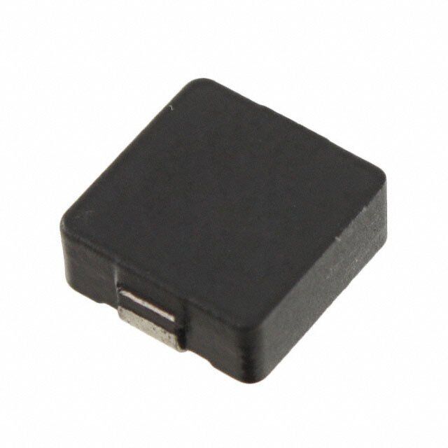
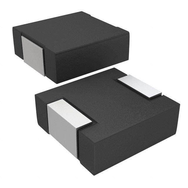
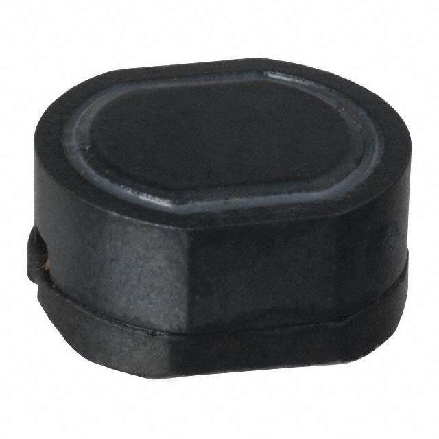
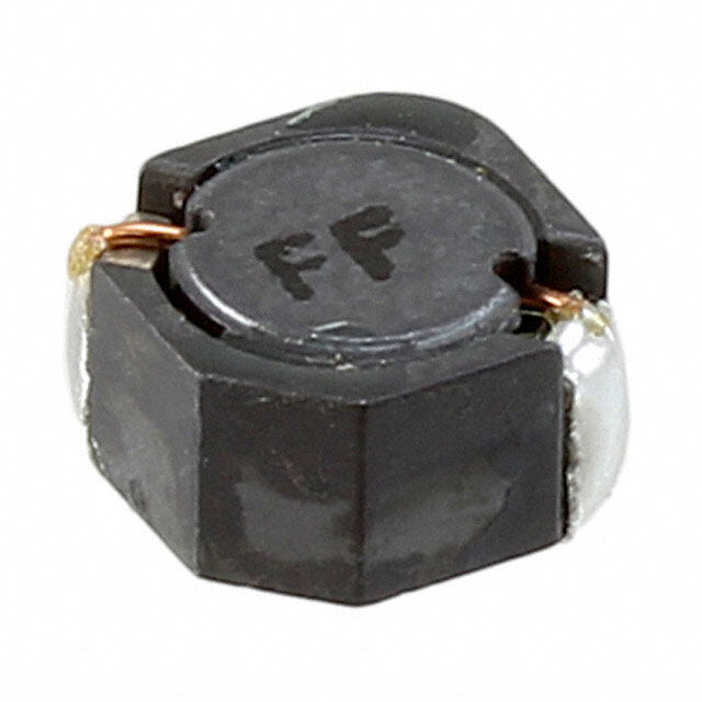
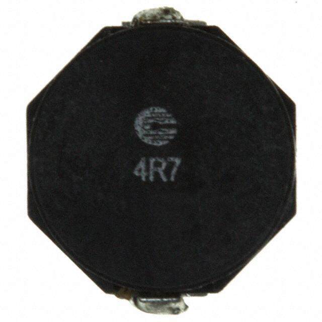
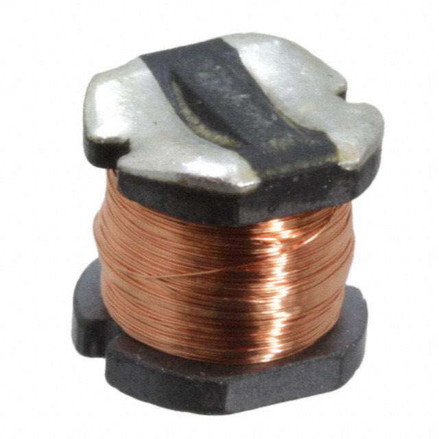
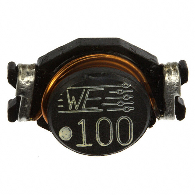
ICGOO电子元器件商城为您提供HCM1305-R47-R由Bussmann/Cooper设计生产,在icgoo商城现货销售,并且可以通过原厂、代理商等渠道进行代购。 HCM1305-R47-R价格参考。Bussmann/CooperHCM1305-R47-R封装/规格:固定值电感器, 470nH 屏蔽 绕线 电感器 38A 0.92 毫欧最大 非标准 。您可以下载HCM1305-R47-R参考资料、Datasheet数据手册功能说明书,资料中有HCM1305-R47-R 详细功能的应用电路图电压和使用方法及教程。
Eaton - Electronics Division 的固定值电感器型号 HCM1305-R47-R 是一款高性能磁性元件,广泛应用于电力电子领域。以下是其主要应用场景:

 1. 电源转换
   - 开关电源 (SMPS):HCM1305-R47-R 可用于 DC-DC 和 AC-DC 转换器中的滤波和储能环节,确保稳定的电流输出。
   - 逆变器:在光伏逆变器、UPS 系统等中,该电感器可用于平滑电流波动,提高效率。

 2. 滤波电路
   - EMI 滤波:作为共模或差模电感的一部分,用于抑制电磁干扰(EMI),保证设备符合 EMC 标准。
   - 信号滤波:在高频信号处理中,该电感器可滤除不需要的频率成分,提升信号质量。

 3. 电机驱动
   - 在电机控制电路中,HCM1305-R47-R 可用于电流平滑和功率因数校正(PFC),以减少电流纹波并提高系统稳定性。

 4. 汽车电子
   - 应用于车载电子系统,如信息娱乐系统、ADAS(高级驾驶辅助系统)和电动助力转向系统(EPS),提供高可靠性和抗振性能。

 5. 工业自动化
   - 在工业控制系统中,用于 PLC、变频器和伺服驱动器的电源模块,确保设备运行稳定。

 6. 通信设备
   - 在基站、路由器和其他通信设备中,该电感器可用于电源管理和信号完整性优化。

 特点与优势
- 高饱和电流:适用于大电流应用场合。
- 低直流电阻 (DCR):减少功耗,提高效率。
- 紧凑设计:适合空间受限的应用环境。
- 高可靠性:满足严苛的工作条件,如高温、高湿和振动环境。

总之,HCM1305-R47-R 以其出色的电气特性和机械性能,成为众多电力电子应用的理想选择。
| 参数 | 数值 |
| 产品目录 | |
| DC电阻(DCR) | 0.92 毫欧最大 |
| 描述 | INDUCTOR HIGH CURRENT 0.47UH SMD固定电感器 0.47uH 65A SMD HIGH CURRENT |
| 产品分类 | |
| 品牌 | Coiltronics / Eaton |
| 产品手册 | |
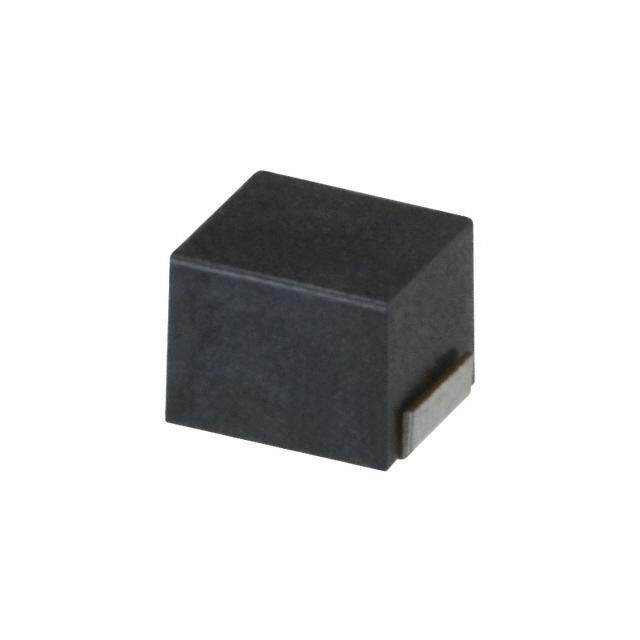
| 产品图片 |
|
| rohs | 符合RoHS无铅 / 符合限制有害物质指令(RoHS)规范要求 |
| 产品系列 | 固定电感器,Coiltronics / Eaton HCM1305-R47-RHCM1305 |
| 数据手册 | |
| 产品型号 | HCM1305-R47-R |
| 不同频率时的Q值 | - |
| 产品 | Power Inductors |
| 产品目录绘图 |
|
| 产品种类 | 固定电感器 |
| 供应商器件封装 | - |
| 其它名称 | 513-1709-6 |
| 包装 | Digi-Reel® |
| 单位重量 | 453.592 mg |
| 商标 | Coiltronics / Eaton |
| 外壳宽度 | 12.2 mm |
| 外壳长度 | 13.3 mm |
| 外壳高度 | 5 mm |
| 大小/尺寸 | 0.524" 长 x 0.480" 宽 (13.30mm x 12.20mm) |
| 安装类型 | 表面贴装 |
| 容差 | 20 % |
| 封装 | Reel |
| 封装/外壳 | 非标准 |
| 屏蔽 | Shielded |
| 工作温度 | -55°C ~ 125°C |
| 工作温度范围 | - 55 C to + 125 C |
| 工厂包装数量 | 400 |
| 最大直流电流 | 65 A |
| 最大直流电阻 | 920 uOhms |
| 材料-磁芯 | 铁粉 |
| 标准包装 | 1 |
| 测试频率 | 100 kHz |
| 电感 | 470 nH |
| 电流-饱和值 | 65A |
| 端接类型 | SMD/SMT |
| 类型 | High Current Inductor |
| 系列 | HCM1305 |
| 芯体材料 | Powdered Iron |
| 频率-测试 | 100kHz |
| 频率-自谐振 | - |
| 额定电流 | 38A |
| 高度-安装(最大值) | 0.197"(5.00mm) |


-R.jpg)


PDF Datasheet 数据手册内容提取
Effective September 2017 Technical Data 4371 Supersedes June 2014 HCM1305 High current power inductors Applications • Voltage Regulator Module (VRM) • Multi-phase regulators • Point-of-load modules • Desktop and server VRMs and EVRDs • Base station equipment • Notebook and laptop regulators • Battery power systems • Graphics cards • Data networking and storage systems Product features Environmental data • High current carrying capacity • Storage temperature range (component): -55 °C to +125 °C • Low core losses • Magnetically shielded, low EMI • Operating temperature range: -55 °C to +125 °C (ambient plus self-temperature rise) • Frequency range up to 5 MHz • Solder reflow temperature: • Inductance range from 0.10 µH to 33 µH J-STD-020 (latest revision) compliant • Current range from 5.2 A to 118 A • 13.8 mm x 12.5 mm footprint surface mount HALOGEN Pb HF package in a 5.0 mm height FREE • Iron powder core material
HCM1305 Technical Data 4371 High current power inductors Effective September 2017 Product specifications DCR (m(cid:49)) DCR (m(cid:49)) OCL1 FLL2 Min. I 3 I 4 @ +20 °C ± @ +20 °C rms sat Part Number6 (µH) ± 20% (µH) (A) (A) nominal maximum K-factor5 HCM1305-R10-R 0.10 0.064 55 118 0.52 0.59 848 HCM1305-R22-R 0.22 0.14 51 110 0.63 0.72 843 HCM1305-R33-R 0.33 0.21 42 80 0.80 0.92 506 HCM1305-R47-R 0.47 0.30 38 65 0.80 0.92 506 HCM1305-R56-R 0.56 0.36 36 55 1.15 1.33 500 HCM1305-R68-R 0.68 0.44 34 54 1.15 1.33 500 HCM1305-R82-R 0.82 0.52 31 53 1.40 1.61 358 HCM1305-1R0-R 1.00 0.64 29 50 2.10 2.42 275 HCM1305-1R5-R 1.50 0.96 23 48 2.75 3.16 225 HCM1305-1R8-R 1.80 1.15 21 40 4.00 4.60 216 HCM1305-2R2-R 2.20 1.41 20 32 4.60 5.29 191 HCM1305-3R3-R 3.30 2.11 15 32 7.70 9.20 170 HCM1305-4R7-R 4.70 3.01 12 27 11.0 12.7 161 HCM1305-5R6-R 5.60 3.58 11.5 22 12.0 13.8 142 HCM1305-6R8-R 6.80 4.35 11 21 13.0 15.0 129 HCM1305-7R8-R 7.80 4.99 10 18.5 16.8 19.4 117 HCM1305-8R2-R 8.20 5.25 9.5 18 17.5 20.1 117 HCM1305-100-R 10.0 6.40 9.0 16 19.0 21.9 90 HCM1305-150-R 15.0 9.60 7.7 13 29.0 33.4 74 HCM1305-220-R 22.0 14.1 6.2 10 45.0 51.8 63 HCM1305-330-R 33.0 21.1 5.2 8 74.5 85.5 48 1.Open Circuit Inductance (OCL) Test Parameters: 100 kHz, 0.25 V , 0.0 Adc, 4.I : Peak current for approximately 20% rolloff at +25 °C. rms sat +25 °C. 5.K-factor: Used to determine B for core loss (see graph). B = K * L * (cid:54)I. p-p p-p 2.Full Load Inductance (FLL) Test Parameters: 100 kHz, 0.25 V , I , @ +25 ° B : (Gauss), K: (K-factor from table), L: (Inductance in µH), (cid:54)I (Peak to peak rms sat p-p C. ripple current in amps). 3. Irms: DC current for an approximate temperature rise of 40 °C without core 6. Part Number Definition: HCM1305-yyy-R loss. Derating is necessary for AC currents. PCB layout, trace thickness and -HCM1305 = Product code and size width, air-flow, and proximity of other heat generating components will affect yyy= Inductance value in µH, R = decimal point, the temperature rise. It is recommended that the temperature of the part not if no R is present then third character = number of zeros. exceed +125 °C under worst case operating conditions verified in the end “-R” suffix = RoHS compliant application. 2 www.eaton.com/electronics
HCM1305 Technical Data 4371 High current power inductors Effective September 2017 Dimensions- mm Top View Side View Bottom View Recommended Pad Layout Schematic 13.3±0.5 5.0 max. 2.54±0.3 3.3 4.0±0.5 xxx 12.2±0.3 7.7 typ. 14.2 wlyy R 4.9 8.5 typ. Part Marking: xxx = Inductance value in µH, R = decimal point, if no R is present, third character = number of zeros, wlyy = (Date Code), R = (Revision Level) All soldering surfaces to be coplanar within 0.10 millimeters. Tolerances are ±0.3 millimeters unless stated otherwise. Color: Grey. Do not route traces or vias underneath the inductor Packaging information - mm Supplied in tape and reel packaging, 400 parts per 13” diameter reel. www.eaton.com/electronics 3
HCM1305 Technical Data 4371 High current power inductors Effective September 2017 Temperature rise vs. total loss 50.0 40.0 ) C ˚ ( e s Ri 30.0 e r u at r e 20.0 p m e T 10.0 0.0 0.0 0.2 0.4 0.6 0.8 1.0 1.2 1.4 1.6 1.8 2.0 Total Loss (W ) Core loss vs. Bp-p 10000 1MHz 500KH z 300KH z 200KH z 1000 100KH z ) W m ( s s o 100 L e r o C 10 1 100 1000 10000 Bp-p (Gauss) 4 www.eaton.com/electronics
HCM1305 Technical Data 4371 High current power inductors Effective September 2017 Inductance characteristics HCM1305-R33-R HCM1305-R47-R 110% 110% 100% 100% 90% 90% CL 80% CL 80% O O of of % 70% % 70% 60% 60% 50% 50% 40% 40% 0 20 40 60 80 100 120 140 0 20 40 60 80 100 120 Idc (A) Idc (A) HCM1305-R56-R HCM1305-R68-R 110% 110% 100% 100% 90% 90% CL 80% CL 80% O O % of 70% % of 70% 60% 60% 50% 50% 40% 40% 0 20 40 60 80 100 120 0 10 20 30 40 50 60 70 80 Idc (A) Idc (A) HCM1305-R82-R HCM1305-1R0-R 110% 110% 100% 100% 90% 90% CL 80% OCL 80% % of O70% % of 70% 60% 60% 50% 50% 40% 40% 0 10 20 30 40 50 60 70 0 10 20 30 40 50 60 70 80 Idc (A) Idc (A) www.eaton.com/electronics 5
HCM1305 Technical Data 4371 High current power inductors Effective September 2017 Inductance characteristics HCM1305-1R5-R HCM1305-1R8-R 110% 110% 100% 100% 90% 90% OCL 80% OCL 80% % of 70% % of 70% 60% 60% 50% 50% 40% 40% 0 5 10 15 20 25 30 35 40 45 50 55 60 0 5 10 15 20 25 30 35 40 45 50 55 60 Idc (A) Idc (A) HCM1305-2R2-R HCM1305-3R3-R 110% 110% 100% 100% 90% 90% CL 80% CL 80% O O % of 70% % of 70% 60% 60% 50% 50% 40% 40% 0 5 10 15 20 25 30 35 40 45 50 0 5 10 15 20 25 30 35 40 45 50 Idc (A) Idc (A) HCM1305-4R7-R HCM1305-5R6-R 110% 110% 100% 100% 90% 90% CL 80% CL 80% O O % of 70% % of 70% 60% 60% 50% 50% 40% 40% 0 5 10 15 20 25 30 35 0 5 10 15 20 25 30 Idc (A) Idc (A) 6 www.eaton.com/electronics
HCM1305 Technical Data 4371 High current power inductors Effective September 2017 Inductance characteristics HCM1305-6R8-R HCM1305-7R8-R 110% 110% 100% 100% 90% 90% CL 80% CL 80% O O % of 70% % of 70% 60% 60% 50% 50% 40% 40% 0 2 4 6 8 10 12 14 16 18 20 22 24 26 0 5 10 15 20 25 30 Idc (A) Idc (A) HCM1305-8R2-R HCM1305-100-R 110% 110% 100% 100% 90% 90% CL 80% CL 80% O O of of % 70% % 70% 60% 60% 50% 50% 40% 40% 0 2 4 6 8 10 12 14 16 18 20 22 24 26 0 2 4 6 8 10 12 14 16 18 20 22 24 26 Idc (A) Idc (A) HCM1305-150-R HCM1305-220-R 110% 110% 100% 100% 90% 90% CL 80% OCL 80% % of O 70% % of 70% 60% 60% 50% 50% 40% 40% 0 2 4 6 8 10 12 14 16 18 0 2 4 6 8 10 12 14 16 18 20 22 Idc (A) Idc (A) www.eaton.com/electronics 7
HCM1305 Technical Data 4371 High current power inductors Effective September 2017 Inductance characteristics HCM1305-330-R 110% 100% 90% CL 80% O % of 70% 60% 50% 40% 0 2 4 6 8 10 12 14 16 18 Idc (A) 8 www.eaton.com/electronics
HCM1305 Technical Data 4371 High current power inductors Effective September 2017 Solder Reflow Profile TP TTaabbllee 11 -- SSttaannddaarrdd SSnnPPbb SSoollddeerr ((TTcc)) TC -5°C Max. Ramp Up Rate = 3°C/s tP Volume Volume Max. Ramp Down Rate = 6°C/s Package mm3 mm3 Thickness <350 >_350 TL <2.5mm 235°C 220°C Preheat t A >_2.5mm 220°C 220°C e Tsmax atur TTaabbllee 22 -- LLeeaadd ((PPbb)) FFrreeee SSoollddeerr ((TTcc)) per Volume Volume Volume Tem Tsmin ts Package mm3 mm3 mm3 Thickness <350 350 - 2000 >2000 <1.6mm 260°C 260°C 260°C 1.6 – 2.5mm 260°C 250°C 245°C >2.5mm 250°C 245°C 245°C 25°C Time 25°C to Peak Time Reference JDEC J-STD-020 Profile Feature Standard SnPb Solder Lead (Pb) Free Solder Preheat and Soak (cid:129)Temperature min.(Tsmin) 100°C 150°C (cid:129)Temperature max.(Tsmax) 150°C 200°C (cid:129)Time (Tsminto Tsmax) (ts) 60-120 Seconds 60-120 Seconds Average ramp up rate Tsmaxto Tp 3°C/ Second Max. 3°C/ Second Max. Liquidous temperature (TL) 183°C 217°C Time at liquidous (tL) 60-150 Seconds 60-150 Seconds Peak package body temperature (TP)* Table 1 Table 2 Time (tp)** within 5 °C of the specified classification temperature (Tc) 20 Seconds** 30 Seconds** Average ramp-down rate (Tpto Tsmax) 6°C/ Second Max. 6°C/ Second Max. Time 25°C to Peak Temperature 6 Minutes Max. 8 Minutes Max. *Tolerance for peak profile temperature (Tp) is defined as a supplier minimum and a user maximum. ** Tolerance for time at peak profile temperature (tp) is defined as a supplier minimum and a user maximum. Life Support Policy: Eaton does not authorize the use of any of its products for use in life support devices or systems without the express written approval of an officer of the Company. Life support systems are devices which support or sustain life, and whose failure to perform, when properly used in accordance with instructions for use provided in the labeling, can be reasonably expected to result in significant injury to the user. Eaton reserves the right, without notice, to change design or construction of any products and to discontinue or limit distribution of any products. Eaton also reserves the right to change or update, without notice, any technical information contained in this bulletin. Eaton Electronics Division 1000 Eaton Boulevard Cleveland, OH 44122 United States www.eaton.com/electronics © 2017 Eaton All Rights Reserved Eaton is a registered trademark. Printed in USA Publication No. 4371 BU-SB14459 All other trademarks are property September 2017 of their respective owners.