ICGOO在线商城 > 传感器,变送器 > 光学传感器 - 环境光,IR,UV 传感器 > VCNL4000-GS08
 Datasheet下载
- 型号: VCNL4000-GS08
- 制造商: Vishay
- 库位|库存: xxxx|xxxx
- 要求:
| 数量阶梯 | 香港交货 | 国内含税 |
| +xxxx | $xxxx | ¥xxxx |
查看当月历史价格
查看今年历史价格
VCNL4000-GS08产品简介:
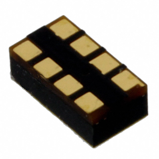
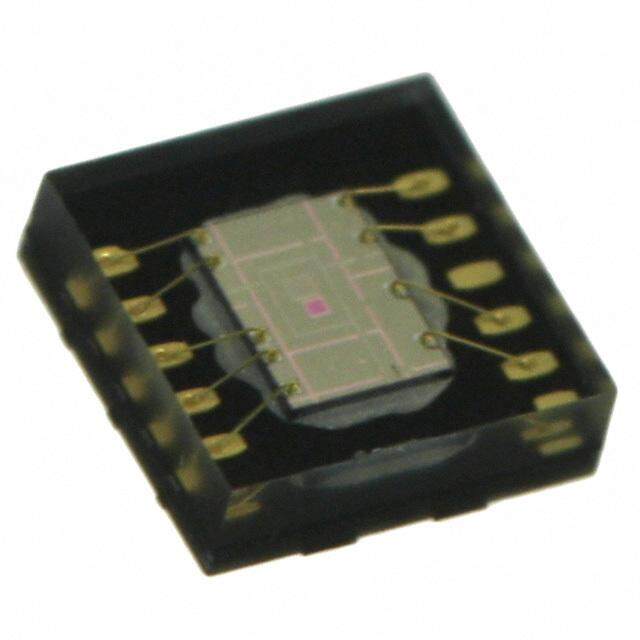
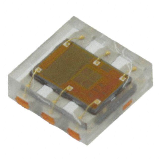
ICGOO电子元器件商城为您提供VCNL4000-GS08由Vishay设计生产,在icgoo商城现货销售,并且可以通过原厂、代理商等渠道进行代购。 VCNL4000-GS08价格参考。VishayVCNL4000-GS08封装/规格:光学传感器 - 环境光,IR,UV 传感器, Optical Sensor Ambient I²C 12-SMD, No Lead。您可以下载VCNL4000-GS08参考资料、Datasheet数据手册功能说明书,资料中有VCNL4000-GS08 详细功能的应用电路图电压和使用方法及教程。
Vishay Semiconductor Opto Division的VCNL4000-GS08是一款集成环境光和接近检测功能的光学传感器。其主要应用场景包括:

1. 智能手机和平板电脑:用于自动调节屏幕亮度,提升用户体验并节省电能;同时通过接近检测功能实现通话时关闭屏幕以防止误触。

2. 可穿戴设备:如智能手表和健身手环,用于环境光感应以优化显示效果并延长电池寿命。

3. 智能家居设备:如智能灯具和温控器,用于根据环境亮度自动调节设备运行状态。

4. 工业和消费类电子产品:如打印机、自动售货机和家电设备,用于节能控制和用户交互检测。

该传感器体积小巧、功耗低、集成度高,适合对空间和功耗敏感的应用场景。
| 参数 | 数值 |
| 产品目录 | |
| 描述 | IC OPTICAL SENSOR I2C 12-LLP近程传感器 Proximity/ALS sensor |
| 产品分类 | |
| 品牌 | Vishay Semiconductor Opto DivisionVishay Semiconductors |
| 产品手册 | http://www.vishay.com/doc?83798 |
| 产品图片 |
|
| rohs | 符合RoHS无铅 / 符合限制有害物质指令(RoHS)规范要求 |
| 产品系列 | Vishay Semiconductors VCNL4000-GS08- |
| 数据手册 | |
| 产品型号 | VCNL4000-GS08VCNL4000-GS08 |
| 产品种类 | 近程传感器 |
| 供应商器件封装 | 12-LLP(3.95x3.95) |
| 其它名称 | 751-1505-6 |
| 包装 | Digi-Reel® |
| 商标 | Vishay Semiconductors |
| 安装类型 | 表面贴装 |
| 安装风格 | SMD/SMT |
| 封装 | Reel |
| 封装/外壳 | 12-SMD,扁平引线 |
| 工作温度 | -25°C ~ 85°C |
| 带接近传感器 | 是 |
| 感应方式 | Optical |
| 感应距离 | 1 mm to 200 mm |
| 最大工作温度 | + 85 C |
| 最小工作温度 | - 25 C |
| 标准包装 | 1 |
| 波长 | - |
| 电压-电源 | 2.5 V ~ 3.6 V |
| 电源电压 | 3.6 V |
| 类型 | 环境 |
| 系列 | VCNL |
| 输出类型 | I²C |
| 输出配置 | Digital |
| 配用 | /product-detail/zh/VCNL4000DEMOKIT/VCNL4000DEMOKIT-ND/2640791 |


- 商务部:美国ITC正式对集成电路等产品启动337调查
- 曝三星4nm工艺存在良率问题 高通将骁龙8 Gen1或转产台积电
- 太阳诱电将投资9.5亿元在常州建新厂生产MLCC 预计2023年完工
- 英特尔发布欧洲新工厂建设计划 深化IDM 2.0 战略
- 台积电先进制程称霸业界 有大客户加持明年业绩稳了
- 达到5530亿美元!SIA预计今年全球半导体销售额将创下新高
- 英特尔拟将自动驾驶子公司Mobileye上市 估值或超500亿美元
- 三星加码芯片和SET,合并消费电子和移动部门,撤换高东真等 CEO
- 三星电子宣布重大人事变动 还合并消费电子和移动部门
- 海关总署:前11个月进口集成电路产品价值2.52万亿元 增长14.8%
PDF Datasheet 数据手册内容提取
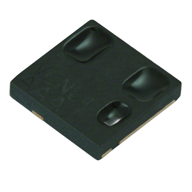
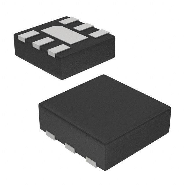
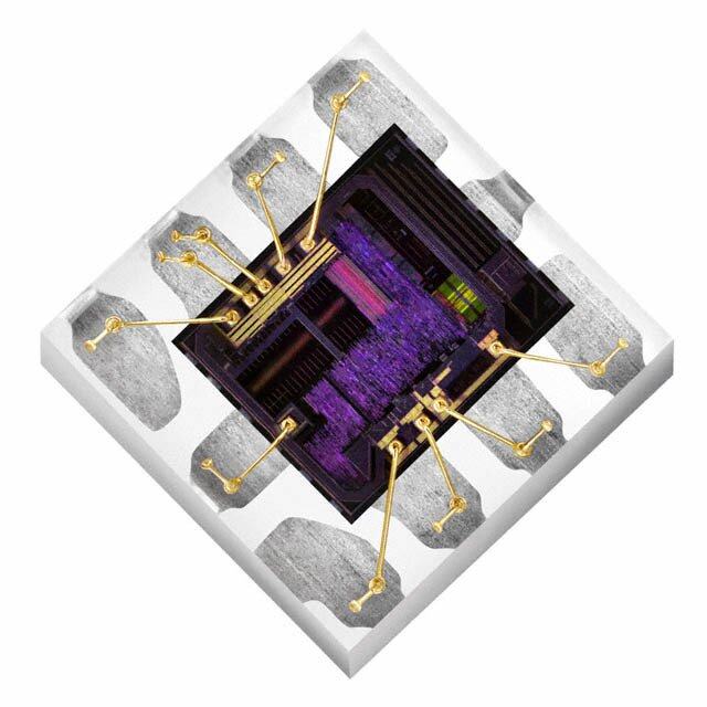
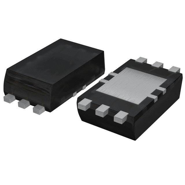
VCNL4000 www.vishay.com Vishay Semiconductors Fully Integrated Proximity and Ambient Light Sensor with Infrared Emitter and I2C Interface FEATURES • Package type: surface mount • Dimensions (L x W x H in mm): 3.95 x 3.95 x 0.75 • Integrated module with ambient light sensor, proximity sensor and signal conditioning IC • Supply voltage range V : 2.5 V to 3.6 V DD • Supply voltage range IR anode: 2.5 V to 5 V • Communication via I2C interface • I2C Bus H-level range: 1.7 V to 5 V • Floor life: 168 h, MSL 3, acc. J-STD-020 GND • Low stand by current consumption: 1.5 μA 12 • Material categorization: For definitions of compliance IR anode 1 11 nc please see www.vishay.com/doc?99912 IR cathode 2 10 nc PROXIMITY FUNCTION IR cathode 3 9 nc • Built in infrared LED and photo-pin-diode for proximity SDA 4 8 nc function SCL 5 7 V DD • 16 bit effective resolution for proximity detection range 6 ensures excellent cross talk immunity 22297-1 GND • Programmable LED drive current from 10 mA to 200 mA (in 10 mA steps) DESCRIPTION • Excellent ambient light suppression by signal modulation VCNL4000 is a fully integrated proximity and ambient light • Proximity distance up to 200 mm digital 16 bit resolution sensor in a miniature lead less package (LLP) for surface mounting. It includes a signal AMBIENT LIGHT FUNCTION processing IC and supports an easy to use I2C bus • Built in ambient light photo-pin-diode with close to human communication interface. eye sensitivity characteristic APPLICATIONS • 16 bit dynamic range for ambient light detection from 0.25 lx to 16 klx • Proximity sensor for mobile devices (e.g. smart phones, touch phones, PDA, GPS) for touch screen locking, power • 100 Hz and 120 Hz flicker noise rejection saving, etc. • Integrated ambient light function for display/keypad contrast control and dimming of mobile devices • Proximity/optical switch for consumer, computing and industrial devices and displays • Dimming control for consumer, computing and industrial displays PRODUCT SUMMARY OPERATING I2C BUS AMBIENT AMBIENT OPERATING LED PULSE VOLTAGE VOLTAGE LIGHT LIGHT OUTPUT PART NUMBER RANGE CURRENT (1) RANGE RANGE RANGE RESOLUTION CODE (mm) (mA) (V) (V) (lx) (lx) VCNL4000 1 to 200 2.5 to 3.6 1.7 to 5 10 to 200 0.25 to 16 383 0.25 16 bit, I2C Note (1) Adjustable through I2C interface Rev. 1.8, 10-May-12 1 Document Number: 83798 For technical questions, contact: sensorstechsupport@vishay.com THIS DOCUMENT IS SUBJECT TO CHANGE WITHOUT NOTICE. THE PRODUCTS DESCRIBED HEREIN AND THIS DOCUMENT ARE SUBJECT TO SPECIFIC DISCLAIMERS, SET FORTH AT www.vishay.com/doc?91000
VCNL4000 www.vishay.com Vishay Semiconductors ORDERING INFORMATION ORDERING CODE PACKAGING VOLUME (1) REMARKS VCNL4000-GS08 MOQ: 1800 pcs Tape and reel 3.95 mm x 3.95 mm x 0.75 mm VCNL4000-GS18 MOQ: 7000 pcs VCNL4000demokit (www.vishay.com/doc?83395) - MOQ: 1 pc - Note (1) MOQ: minimum order quantity ABSOLUTE MAXIMUM RATINGS (T = 25 °C, unless otherwise specified) amb PARAMETER TEST CONDITION SYMBOL MIN. MAX. UNIT Supply voltage V - 0.3 5.5 V DD Operation temperature range T - 25 + 85 °C amb Storage temperature range T - 40 + 85 °C stg Total power dissipation T ≤ 25 °C P 50 mW amb tot Junction temperature T 100 °C j BASIC CHARACTERISTICS (T = 25 °C, unless otherwise specified) amb PARAMETER TEST CONDITION SYMBOL MIN. TYP. MAX. UNIT Supply voltage V 2.5 3.6 V DD Supply voltage IR anode 2.5 5 V I2C Bus H-level range 1.7 5 V Standby current, Current consumption 1.5 2 μA no IRED-operation 2 measurements per second, 4 μA IRED current 20 mA 250 measurements per second, Current consumption 500 μA IRED current 20 mA proximity mode incl. IRED 2 measurements per second, (averaged) 31 μA IRED current 200 mA 250 measurements per second, 3.8 mA IRED current 200 mA 2 measurements per second 2.5 μA averaging = 1 8 measurements per second 10 μA Current consumption ambient averaging = 1 light mode 2 measurements per second 160 μA averaging = 64 8 measurements per second 635 μA averaging = 64 Ambient light resolution Digital resolution (LSB count ) 0.25 lx E = 100 lx Ambient light output V 400 counts averaging = 64 I2C clock rate range f 3400 kHz SCL Rev. 1.8, 10-May-12 2 Document Number: 83798 For technical questions, contact: sensorstechsupport@vishay.com THIS DOCUMENT IS SUBJECT TO CHANGE WITHOUT NOTICE. THE PRODUCTS DESCRIBED HEREIN AND THIS DOCUMENT ARE SUBJECT TO SPECIFIC DISCLAIMERS, SET FORTH AT www.vishay.com/doc?91000
VCNL4000 www.vishay.com Vishay Semiconductors CIRCUIT BLOCK DIAGRAM TEST CIRCUIT GND 12 30 mm x 30 mm IR anode 1 IRED PD 11 nc Kodak gray card IR cathode 2 Proxi 10 nc (18 % reflectivity) m IR cathode 3 9 nc m 0 PD 2 SDA 4 VCNL4000 8 nc d = ASIC Ambi SCL 5 7 V DD VCNL4000 IRED Proxi-PD 22300 6 22299 GND Note • nc must not be electrically connected Pads 8 to 11 are only considered as solder pads BASIC CHARACTERISTICS (T = 25 °C, unless otherwise specified) amb 2.4 100 000 A) μ LED current 200 mA e ( 2.2 d 10 000 Mo 2.0 s) Current Idle 11..86 VVVVDDDDDDDD ==== 3333....6531 VVVV VVDDDD == 22..57 VV mity Value (ct 1100000 LED current 100 mA ply 1.4 VDD = 2.9 V oxi LED current 20 mA p Pr u S 10 - 1.2 Media: Kodak gray card D D Mod. frequency = 390 kHz I 1.0 1 - 50 - 30 - 10 10 30 50 70 90 110 0.1 1 10 100 22301 Tamb - Ambient Temperature (°C) 22303 Distance to Reflecting Card (mm) Fig. 1 - Idle Current vs. Ambient Temperature Fig. 3 - Proximity Value vs. Distance 2.4 250 Mode (μA) 22..02 100 °C RED (mA) 200 VIRED = 2.5 V 128000 mmAA y Current Idle 11..68 852055 °°°CCC ward Current I 110500 8111100246 0000m mmmmAAAAA I - SupplDD 11..24 -- 1400 °°CC I - ForIRED 50 246000 mmmAAA 1.0 0 2.4 2.6 2.8 3.0 3.2 3.4 3.6 3.8 - 60 - 20 20 60 100 140 22302 VDD - Supply Voltage (V) 22304 Tamb - Ambient Temperature (°C) Fig. 2 - Idle Current vs. V Fig. 4 - Forward Current vs. Temperature DD Rev. 1.8, 10-May-12 3 Document Number: 83798 For technical questions, contact: sensorstechsupport@vishay.com THIS DOCUMENT IS SUBJECT TO CHANGE WITHOUT NOTICE. THE PRODUCTS DESCRIBED HEREIN AND THIS DOCUMENT ARE SUBJECT TO SPECIFIC DISCLAIMERS, SET FORTH AT www.vishay.com/doc?91000
VCNL4000 www.vishay.com Vishay Semiconductors 0° 20° 1.1 y 1.0 IF = 100 mA ve Radiant Intensit 00000.....68957 ative Sensitivity 0001....7890 40° ar Displacement - Relatiel 000...243 S - Relrel 0.6 60° ϕ - Angul Ie, r 0.1 80° 0 750 800 850 900 950 1000 1050 0.50.4 0.3 0.2 0.1 0 22305 λ - Wavelength (nm) 22308 Fig. 5 - Relative Radiant Intensity vs. Wavelength Fig. 8 - Relative Radiant Sensitivity vs. Angular Displacement 0° 20° 100 000 y - Relative Radiant Intensitel 00001.....67890 4600°° ϕ - Angular Displacement Ambient Light Signal (cts)101 10000010000 Ir 80° 1 0.50.4 0.3 0.2 0.1 0 0.1 1 10 100 1000 10 000 22306 E - Illuminance (lx) V Fig. 6 - Relative Radiant Intensity vs. Angular Displacement Fig. 9 - Ambient Light Value vs. Illuminance 1.1 y nsitivity 01..90 ponsivit 1.0 Human eye ectral Se 000...687 ctral Res 00..68 p e S p Relative 000...435 elative S 0.4 λS() - rel 00..021 λS() - Rrel 0.02 VCNL4000 400 500 600 700 800 900 1000 1100 400 500 600 700 800 900 1000 1100 22307 λ - Wavelength (nm) 22310 λ - Wavelength (nm) Fig. 7 - Relative Spectral Sensitivity vs. Wavelength Fig. 10 - Relative Spectral Sensitivity vs. Wavelength Rev. 1.8, 10-May-12 4 Document Number: 83798 For technical questions, contact: sensorstechsupport@vishay.com THIS DOCUMENT IS SUBJECT TO CHANGE WITHOUT NOTICE. THE PRODUCTS DESCRIBED HEREIN AND THIS DOCUMENT ARE SUBJECT TO SPECIFIC DISCLAIMERS, SET FORTH AT www.vishay.com/doc?91000
VCNL4000 www.vishay.com Vishay Semiconductors 0° 20° y 1.0 nt Sensitivit 00..89 VHeortriiczaolntal 40° placeme ve Dis ati 0.7 ar el ul S - Rrel 0.6 60° ϕ - Ang 80° 0.50.4 0.3 0.2 0.1 0 22311 Fig. 11 - Relative Radiant Sensitivity vs. Angular Displacement APPLICATION INFORMATION VCNL4000 is a cost effective solution of proximity and ambient light sensor with I2C Bus interface. The standard serial digital interface is easy to access “Proximity Signal” and “Light Intensity” without complex calculation and programming by external controller. 1. Application Circuit 2.5 V to 5 V C1 C2 22 μF 100 nF R1 IR Anode (1) 2.5 V to 3.6 V 10R C4 C3 VDD (7) 10 μF 100 nF Host VCNL4000 Micro Controller SCL (5) I2C Bus Clock SCL GND (6, 12) SDA (4) I2C Bus Data SDA 22312-1 Fig. 12 - Application Circuit (x) = Pin Number Rev. 1.8, 10-May-12 5 Document Number: 83798 For technical questions, contact: sensorstechsupport@vishay.com THIS DOCUMENT IS SUBJECT TO CHANGE WITHOUT NOTICE. THE PRODUCTS DESCRIBED HEREIN AND THIS DOCUMENT ARE SUBJECT TO SPECIFIC DISCLAIMERS, SET FORTH AT www.vishay.com/doc?91000
VCNL4000 www.vishay.com Vishay Semiconductors 2. I2C Interface The VCNL4000 contains twelve 8 bit registers for operation control, parameter setup and result buffering. All registers are accessible via I2C communication. Figure 13 shows the basic I2C communication with VCNL4000. The built in I2C interface is compatible with all I2C modes (standard, fast and high speed). I2C H-level range = 1.7 V to 5 V. Please refer to the I2C specification from NXP for details. Send byte Write command to VCNL4000 S Slave address Wr A Register address A Data byte A P Receive byte Read data from VCNL4000 S Slave address Wr A Register address A P S Slave address Rd A Data byte A P S = start condition Host action P = stop condition A = acknowledge VCNL4000 response 22313 Fig. 13 - Send Byte/Receive Byte Protocol Device Address Register Addresses The VCNL4000 has a fix slave address for the host VCNL4000 has twelve user accessible 8 bit registers. The programming and accessing selection. The predefined 7 bit register addresses are 80h (register #0) to 8Bh (register #11). I2C bus address is set to 0010 011 = 13h. The least significant bit (LSB) defines read or write mode. Accordingly the bus address is set to 0010 011x = 26h for write, 27h for read. REGISTER FUNCTIONS Register #0 Command Register Register address = 80h The register #0 is for starting ambient light or proximity measurements. This register contains 2 flag bits for data ready indication. TABLE 1 - COMMAND REGISTER #0 Bit 7 Bit 6 Bit 5 Bit 4 Bit 3 Bit 2 Bit 1 Bit 0 config_lock als_data_rdy prox_data_rdy als_od prox_od N/A N/A N/A Description config_lock Read only bit. Value = 1 Read only bit. Value = 1 when ambient light measurement data is available in the result registers. This bit als_data_rdy will be reset when one of the corresponding result registers (reg #5, reg #6) is read. Read only bit. Value = 1 when proximity measurement data is available in the result registers. This bit will prox_data_rdy be reset when one of the corresponding result registers (reg #7, reg #8) is read. R/W bit. Starts a single on-demand measurement for ambient light. If averaging is enabled, starts a als_od sequence of readings and stores the averaged result. Result is available at the end of conversion for reading in the registers #5(HB) and #6(LB). R/W bit. Starts a single on-demand measurement for proximity. prox_od Result is available at the end of conversion for reading in the registers #7(HB) and #8(LB). Notes • After a proximity start command [prox_od] a WAIT time of ≥ 400 μs should be inserted before any read out commands. • With setting bit 3 and bit 4 at the same write command, a simultaneously measurement of ambient light and proximity is done. Rev. 1.8, 10-May-12 6 Document Number: 83798 For technical questions, contact: sensorstechsupport@vishay.com THIS DOCUMENT IS SUBJECT TO CHANGE WITHOUT NOTICE. THE PRODUCTS DESCRIBED HEREIN AND THIS DOCUMENT ARE SUBJECT TO SPECIFIC DISCLAIMERS, SET FORTH AT www.vishay.com/doc?91000
VCNL4000 www.vishay.com Vishay Semiconductors Register #1 Product ID Revision Register Register address = 81h. This register contains information about product ID and product revision. Register data value of current revision = 11h. TABLE 2 - PRODUCT ID REVISION REGISTER #1 Bit 7 Bit 6 Bit 5 Bit 4 Bit 3 Bit 2 Bit 1 Bit 0 Product ID Revision ID Description Product ID Read only bits. Value = 1 Revision ID Register #2 without Function in Current Version Register address = 82h. Register #3 LED Current Setting for Proximity Mode Register address = 83h. This register is to set the LED current value for proximity measurement. The value is adjustable in steps of 10 mA from 0 mA to 200 mA. This register also contains information about the used device fuse program ID. TABLE 3 - IR LED CURRENT REGISTER #3 Bit 7 Bit 6 Bit 5 Bit 4 Bit 3 Bit 2 Bit 1 Bit 0 Fuse prog ID IR LED current value Description Read only bits. Fuse prog ID Information about fuse program revision used for initial setup/calibration of the device. R/W bits. IR LED current = Value (dec.) x 10 mA. IR LED current value Valid Range = 0 to 20d. e.g. 0 = 0 mA , 1 = 10 mA, …., 20 = 200 mA (2 = 20 mA = DEFAULT) LED Current is limited to 200 mA for values higher as 20d. Register #4 Ambient Light Parameter Register Register address = 84h. TABLE 4 - AMBIENT LIGHT PARAMETER REGISTER #4 Bit 7 Bit 6 Bit 5 Bit 4 Bit 3 Bit 2 Bit 1 Bit 0 Cont. conv. Auto offset Averaging function N/A mode compensation (number of measurements per run) Description R/W bit. Continuous conversion mode. Bit 7 Enable = 1; Disable = 0 = DEFAULT Cont. conversion mode This function can be used for performing faster ambient light measurements. Please refer to the application information chapter 3.3 for details about this function. R/W bit. Automatic offset compensation. Enable = 1 = DEFAULT; Disable = 0 Bit 3 In order to compensate a technology, package or temperature related drift of the ambient light values Auto offset compensation there is a built in automatic offset compensation function. With active auto offset compensation the offset value is measured before each ambient light measurement and subtracted automatically from actual reading. R/W bits. Averaging function. Bit values sets the number of single conversions done during one measurement cycle. Result is the Bit 0 to bit 2 average value of all conversions. Averaging function Number of conversions = 2decimal_value e.g. 0 = 1 conv., 1 = 2 conv, 2 = 4 conv., ….7 = 128 conv. DEFAULT = 32 conv. Rev. 1.8, 10-May-12 7 Document Number: 83798 For technical questions, contact: sensorstechsupport@vishay.com THIS DOCUMENT IS SUBJECT TO CHANGE WITHOUT NOTICE. THE PRODUCTS DESCRIBED HEREIN AND THIS DOCUMENT ARE SUBJECT TO SPECIFIC DISCLAIMERS, SET FORTH AT www.vishay.com/doc?91000
VCNL4000 www.vishay.com Vishay Semiconductors Register #5 and #6 Ambient Light Result Register Register address = 85h and 86h. These registers are the result registers for ambient light measurement readings. The result is a 16 bit value. The high byte is stored in register #5 and the low byte in register #6. TABLE 5 - AMBIENT LIGHT RESULT REGISTER #5 Bit 7 Bit 6 Bit 5 Bit 4 Bit 3 Bit 2 Bit 1 Bit 0 Description Read only bits. High byte (15:8) of ambient light measurement result TABLE 6 - AMBIENT LIGHT RESULT REGISTER #6 Bit 7 Bit 6 Bit 5 Bit 4 Bit 3 Bit 2 Bit 1 Bit 0 Description Read only bits. Low byte (7:0) of ambient light measurement result Register #7 and #8 Proximity Measurement Result Register Register address = 87h and 88h. These registers are the result registers for proximity measurement readings. The result is a 16 bit value. The high byte is stored in register #7 and the low byte in register #8. TABLE 7 - PROXIMITY RESULT REGISTER #7 Bit 7 Bit 6 Bit 5 Bit 4 Bit 3 Bit 2 Bit 1 Bit 0 Description Read only bits. High byte (15:8) of proximity measurement result TABLE 8 - PROXIMITY RESULT REGISTER #8 Bit 7 Bit 6 Bit 5 Bit 4 Bit 3 Bit 2 Bit 1 Bit 0 Description Read only bits. Low byte (7:0) of proximity measurement result Register #9 Proximity Measurement Signal Frequency Register address = 89h. TABLE 9 - PROXIMITY MEASUREMENT SIGNAL FREQUENCY #9 Bit 7 Bit 6 Bit 5 Bit 4 Bit 3 Bit 2 Bit 1 Bit 0 N/A Proximity frequency Description R/W bits. Setting the proximity IR test signal frequency. The proximity measurement is using a square IR signal as measurement signal. Four different values are possible: Bit 0 and 1 00 = 3.125 MHz Proximity frequency 01 = 1.5625 MHz 02 = 781.25 kHz (DEFAULT) 03 = 390.625 kHz Rev. 1.8, 10-May-12 8 Document Number: 83798 For technical questions, contact: sensorstechsupport@vishay.com THIS DOCUMENT IS SUBJECT TO CHANGE WITHOUT NOTICE. THE PRODUCTS DESCRIBED HEREIN AND THIS DOCUMENT ARE SUBJECT TO SPECIFIC DISCLAIMERS, SET FORTH AT www.vishay.com/doc?91000
VCNL4000 www.vishay.com Vishay Semiconductors Register #10 Proximity Modulator Timing Adjustment Register address = 8Ah. TABLE 10 - PROXIMITY MODULATOR TIMING ADJUSTMENT #10 Bit 7 Bit 6 Bit 5 Bit 4 Bit 3 Bit 2 Bit 1 Bit 0 Modulation delay time N/A Modulation dead Time Description R/W bits. Setting a delay time between IR LED signal and IR input signal evaluation. This function is for compensation of delays from IR LED and IR photo diode. Modulation delay time Also in respect to the possibility for setting different proximity signal frequency. Correct adjustment is optimizing measurement signal level. R/W bits. Setting a dead time in evaluation of IR signal at the slopes of the IR signal. Modulation dead Time This function is for reducing of possible disturbance effects. This function is reducing signal level and should be used carefully. Note • The settings for best performance will be provided by Vishay. With first samples this is evaluated to: delay time = 4 and dead time = 1, with that register #10 should be programmed with: 129 (dez.) Register #11 Ambient IR Light Level Register Register address = 8Bh. This register is not intended to be used by customer. 3. IMPORTANT APPLICATION HINTS AND EXAMPLES 3.1 Receiver standby mode In standby mode the receiver has the lowest current consumption of about 1.5 μA. In this mode only the I2C interface is active. This is always valid, when there are no measurement demands for proximity and ambient light executed. Also the current sink for the IR-LED is inactive, so there is no need for changing register #3 (IR LED current). 3.2 Data Read In order to get a certain register value, the register has to be addressed without data like shown in the following scheme. After this register addressing, the data from the addressed register is written after a subsequent read command. Receive byte Read data from VCNL4000 S Slave address Wr A Register address A P S Slave address Rd A Data byte A P S = start condition Host action P = stop condition A = acknowledge VCNL4000 response 22314 Fig. 14 - Send Byte/Receive Byte Protocol The stop condition between these write and read sequences is not mandatory. It works also with a repeated start condition. Note • For reading out 2 (or more) subsequent registers like the result registers, it is not necessary to address each of the registers separately. After one read command the internal register counter is increased automatically and any subsequent read command is accessing the next register. Example: read register “Ambient Light Result Register” #5 and #6: Addressing:command: 26h, 85h (VCNL4000_I2C_Bus_Write_Adr., Ambient Light Result Register #5 [85]) Read register #5:command: 27h, data (VCNL4000_I2C_Bus_Read_Adr., {High Byte Data of Ambient Light Result Register #5 [85])} Read register #6:command: 27h, data (VCNL4000_I2C_Bus_Read_Adr., {Low Byte Data of Ambient Light Result Register #6 [86])} Rev. 1.8, 10-May-12 9 Document Number: 83798 For technical questions, contact: sensorstechsupport@vishay.com THIS DOCUMENT IS SUBJECT TO CHANGE WITHOUT NOTICE. THE PRODUCTS DESCRIBED HEREIN AND THIS DOCUMENT ARE SUBJECT TO SPECIFIC DISCLAIMERS, SET FORTH AT www.vishay.com/doc?91000
VCNL4000 www.vishay.com Vishay Semiconductors 3.3 Continuous Conversion Mode in Ambient Light Measurement In the following is a detail description of the function “continuous conversion” (bit 7 of register #4) Standard mode (bit 7 of reg #4 = 0): In standard mode the ambient light measurement is done during a fixed time frame of 100 ms. The single measurement itself takes actually only appr. 300 μs. The following figures show examples of this measurement timing in standard mode using averaging function 2 and 8 as examples for illustration (possible values up to 128). Start Start 50ms 12.5 ms 100 ms 100ms 22316 22315 Fig. 15 - Ambient Light Measurement with Averaging = 2; Fig. 16 - Ambient Light Measurement with Averaging = 8; Final Measurement Result = Average of these 2 Measurements Final Measurement Result = Average of these 8 Measurements Note • ≥ Independent of setting of averaging the result is available only after 100 ms. Continuous conversion mode (bit7 of reg #4 = 1): In continuous conversion mode the single measurements are done directly subsequent after each other. See following examples in figure 17 and 18 Start Start 460 μs 460 μs 4.2 ms 1.5 ms 22317 22318 Fig. 17 - Ambient Light Measurement with Averaging = 2; Fig. 18 - Ambient Light Measurement with Averaging = 8; using Continuous Conversion Mode using Continuous Conversion Mode Rev. 1.8, 10-May-12 10 Document Number: 83798 For technical questions, contact: sensorstechsupport@vishay.com THIS DOCUMENT IS SUBJECT TO CHANGE WITHOUT NOTICE. THE PRODUCTS DESCRIBED HEREIN AND THIS DOCUMENT ARE SUBJECT TO SPECIFIC DISCLAIMERS, SET FORTH AT www.vishay.com/doc?91000
VCNL4000 www.vishay.com Vishay Semiconductors PACKAGE DIMENSIONS in millimeters 4 x 0.75 = 3 Cathode Emitter 0.35 ± 0.05 Anode Emitter SDA SCL 0.75 ± 0.05 0.475 0.475 Pinning 0.175 ± 0.05 Bottom view 0.175 ± 0.05 555 GND 0. GND 6 2 1. 8 1. 5 0 0. ± 0.05 0.545 0.4 ± ePleacdt rmicuasl tc noontn beceted VDD 4 0. VDD Pinning 0.175 ± 0.05 Top view 0.47 ± 0.05 technical drawings 0.475 according to DIN GND specifications GND 5 15 0.7 0. 3.95 SDA SCL Cathode Emitter 0.935 Anode Emitter Proposed PCB Footprint 0.2 (3.95) 0.2 5 9 3.205 3.355 3. 0.805 4 0. 4 5) 0. 9 735 (3. 0. 0.985 8 1. 26 2.615 1. 0.35 (10x) 05 8 0. 0.75 Drawing-No.: 6.550-5302.01-4 Not indicated tolerances ± 0.1 Issue: prel; 16.02.10 4 x 0.75 = 3 22320 Rev. 1.8, 10-May-12 11 Document Number: 83798 For technical questions, contact: sensorstechsupport@vishay.com THIS DOCUMENT IS SUBJECT TO CHANGE WITHOUT NOTICE. THE PRODUCTS DESCRIBED HEREIN AND THIS DOCUMENT ARE SUBJECT TO SPECIFIC DISCLAIMERS, SET FORTH AT www.vishay.com/doc?91000
VCNL4000 www.vishay.com Vishay Semiconductors TAPE AND REEL DIMENSIONS in millimeters X Unreel direction Reel size "Y" GS 08 Ø 180 ± 2 = 1800 pcs. GS 18 Ø 330 ± 2 = 7000 pcs. n. Tape position mi 0 coming out from reel Ø 6 2 ± 0. 5 Y Ø Not indicated tolerances ± 0.1 Ø 21 ± 0.8 Ø 13 ± 0.2 Label posted here 12.4 + 2 18.4 max. Parts mounted Empty Leader 400mm min. 100mm min. with cover tape Leader and trailer tape: Direction of pulling out Empty Trailer 200mm min. technical drawings according to DIN specifications X 2:1 4.25 0.9 8 Ø 1.5 4 5 0.3 2 1.7 5 3 5. 0. 5 ± 4.2 12 Drawing-No.: 9.800-510301-4 Issue: prel; 02.12.09 22319 Rev. 1.8, 10-May-12 12 Document Number: 83798 For technical questions, contact: sensorstechsupport@vishay.com THIS DOCUMENT IS SUBJECT TO CHANGE WITHOUT NOTICE. THE PRODUCTS DESCRIBED HEREIN AND THIS DOCUMENT ARE SUBJECT TO SPECIFIC DISCLAIMERS, SET FORTH AT www.vishay.com/doc?91000
VCNL4000 www.vishay.com Vishay Semiconductors SOLDER PROFILE DRYPACK Devices are packed in moisture barrier bags (MBB) to prevent the products from moisture absorption during 300 transportation and storage. Each bag contains a desiccant. max. 260 °C 255 °C 250 240 °C 245 °C FLOOR LIFE 217 °C C) 200 Floor life (time between soldering and removing from MBB) e (° max. 30 s must not exceed the time indicated on MBB label: ur 150 at Floor life: 168 h er max. 120 s max. 100 s mp 100 Conditions: Tamb < 30 °C, RH < 60 % e T Moisture sensitivity level 3, acc. to J-STD-020. 50 max. ramp up 3 °C/s max. ramp down 6 °C/s DRYING 0 0 50 100 150 200 250 300 In case of moisture absorption devices should be baked 19841 Time (s) before soldering. Conditions see J-STD-020 or label. Devices taped on reel dry using recommended conditions Fig. 19 - Lead (Pb)-free Reflow Solder Profile acc. J-STD-020 192 h at 40 °C (+ 5 °C), RH < 5 %. Rev. 1.8, 10-May-12 13 Document Number: 83798 For technical questions, contact: sensorstechsupport@vishay.com THIS DOCUMENT IS SUBJECT TO CHANGE WITHOUT NOTICE. THE PRODUCTS DESCRIBED HEREIN AND THIS DOCUMENT ARE SUBJECT TO SPECIFIC DISCLAIMERS, SET FORTH AT www.vishay.com/doc?91000