ICGOO在线商城 > USB-COM485-PLUS1
 Datasheet下载
- 型号: USB-COM485-PLUS1
- 制造商: FTDI
- 库位|库存: xxxx|xxxx
- 要求:
| 数量阶梯 | 香港交货 | 国内含税 |
| +xxxx | $xxxx | ¥xxxx |
查看当月历史价格
查看今年历史价格
USB-COM485-PLUS1产品简介:
ICGOO电子元器件商城为您提供USB-COM485-PLUS1由FTDI设计生产,在icgoo商城现货销售,并且可以通过原厂、代理商等渠道进行代购。 提供USB-COM485-PLUS1价格参考¥341.43-¥376.33以及FTDIUSB-COM485-PLUS1封装/规格参数等产品信息。 你可以下载USB-COM485-PLUS1参考资料、Datasheet数据手册功能说明书, 资料中有USB-COM485-PLUS1详细功能的应用电路图电压和使用方法及教程。
| 参数 | 数值 |
| 产品目录 | |
| 描述 | MOD USB RS485 CONVERTER 1 CH界面模块 USB to RS485 Convrtr Assembly 1 DB9 Port |
| 产品分类 | 适配器界面模块 |
| 品牌 | FTDI |
| 产品手册 | |
| 产品图片 |
|
| rohs | 符合RoHS无铅 / 符合限制有害物质指令(RoHS)规范要求 |
| 产品系列 | FTDI USB-COM485-PLUS1USB-COM-Plus |
| 数据手册 | |
| 产品型号 | USB-COM485-PLUS1 |
| 产品 | Converters |
| 产品目录页面 | |
| 产品种类 | 界面模块 |
| 其它名称 | 768-1038 |
| 商标 | FTDI |
| 封装 | Bulk |
| 尺寸 | 57 mm x 37 mm x 14 mm |
| 工作电源电压 | 5 V |
| 工厂包装数量 | 5 |
| 接口类型 | RS-485, USB |
| 数据速率 | 3 Mbps, 12 Mbps |
| 最大工作温度 | + 85 C |
| 最大数据速率 | 12 Mbit/s |
| 最小工作温度 | - 40 C |
| 标准包装 | 5 |
| 类型 | USB to RS-485 |
| 连接器类型 | USB-B 至 DB9 |
| 通道/端口数量 | 1 Port |
| 零件号别名 | USB-COM485-PLUS-1 |

/USB-COM485-PLUS-1.jpg)


- 商务部:美国ITC正式对集成电路等产品启动337调查
- 曝三星4nm工艺存在良率问题 高通将骁龙8 Gen1或转产台积电
- 太阳诱电将投资9.5亿元在常州建新厂生产MLCC 预计2023年完工
- 英特尔发布欧洲新工厂建设计划 深化IDM 2.0 战略
- 台积电先进制程称霸业界 有大客户加持明年业绩稳了
- 达到5530亿美元!SIA预计今年全球半导体销售额将创下新高
- 英特尔拟将自动驾驶子公司Mobileye上市 估值或超500亿美元
- 三星加码芯片和SET,合并消费电子和移动部门,撤换高东真等 CEO
- 三星电子宣布重大人事变动 还合并消费电子和移动部门
- 海关总署:前11个月进口集成电路产品价值2.52万亿元 增长14.8%


PDF Datasheet 数据手册内容提取
Future Technology Devices International Ltd USB-COM485-PLUS1 Datasheet Document Reference No.: FT_000132 Version 1.21 Issue Date: 2010-10-06 Future Technology Devices International Ltd (FTDI) Unit 1, 2 Seaward Place, Centurion Business Park, Glasgow, G41 1HH, United Kingdom Tel.: +44 (0) 141 429 2777 Fax: + 44 (0) 141 429 2758 E-Mail (Support): support1@ftdichip.com Web: http://www.ftdichip.com Neither the whole nor any part of the information contained in, or the product described in this manual, may be adapted or reproduced in any material or electronic form without the prior written consent of the copyright holder. This product and its documentation are supplied on an as-is basis and no warranty as to their suitability for any particular purpose is either made or implied. Future Technology Devices International Ltd will not accept any claim for damages howsoever arising as a result of use or failure of this product. Your statutory rights are not affected. This product or any variant of it is not intended for use in any medical appliance, device or system in which the failure of the product might reasonably be expected to result in personal injury. This document provides preliminary information that may be subject to change without notice. No freedom to use patents or other intellectual property rights is implied by the publication of this document. Future Technology Devices International Ltd, Unit1, 2 Seaward Place, Centurion Business Park, Glasgow, G41 1HH, United Kingdom. Scotland Registered Number: SC136640 Copyright © 2010 Future Technology Devices International Limited
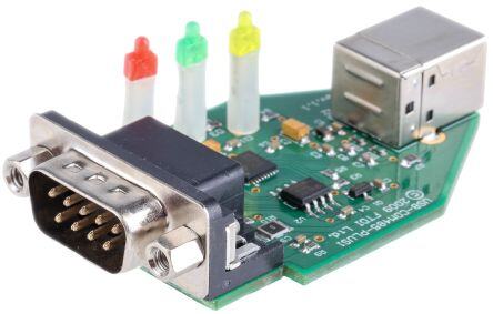
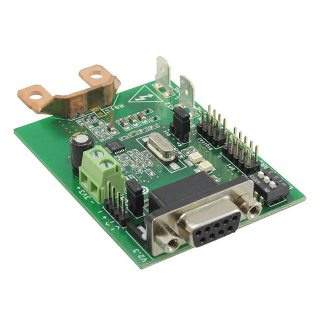
Document Reference No.: FT_000132 USB-COM485-PLUS1 Datasheet Version 1.21 Clearance No.: FTDI# 95 1 Introduction 1.1 Functional Description The USB-COM-Plus modules are a family of communication devices. This model, USB-COM485-Plus1, provides a simple method of adapting legacy serial devices with RS485 interfaces to modern USB ports. This is accomplished by incorporating the industry standard FTDI FT232R USB-Serial bridge chip. The integrated electronics of the USB-COM485-PLUS1 utilise the FTDI FT232R and includes RS485 level shifters plus TXD/RXD LEDs to provide a visual indication of data traffic through the module. Figure 1.1 USB-COM485-Plus1 The module uses a standard USB-B device connector for connection to an upstream host or hub port. RS485-level signals are available on an industry-standard DE-9P connector. The maximum RS485-level data rate is 3Mbps. Pin 9 of the DE-9P connector can provide +5V DC at 250mA. The USB-COM485-Plus1 module requires USB device drivers, available free from www.ftdichip.com, which are used to make the USB-COM485-Plus1 appear as a Virtual COM Port (VCP). This allows existing serial communications software, such as HyperTerminal, to exchange data through the USB-COM485-Plus1 to a legacy RS485 peripheral device. Copyright © 2010 Future Technology Devices International Limited 1
Document Reference No.: FT_000132 USB-COM485-PLUS1 Datasheet Version 1.21 Clearance No.: FTDI# 95 1.2 LED Description The USB-COM485-Plus1 uses three LEDs to indicate a valid link as well as data traffic according to the following table: LED Color Function Description Yellow Enumerated ON when USB-COM485-Plus1 is configured and ready Flashes when data is transmitted from the USB-COM485-Plus1 to the Green TxD Activity attached RS485 device Flashes when data is transmitted from the attached RS485 device to the Red RxD Activity USB-COM485-Plus1 Table 1.1 LED Description 1.3 Block Diagram USB B FTDI FT232R RS485 DE-9P Client USB Serial Bridge Level Shifter Connector Connector Figure 1.2 USB-COM485-Plus1 Block Diagram 1.3.1 Block description USB B Client Connector This connector provides the interface for connection to a USB Host or Hub port. The maximum cable length is 5 meters, according to the USB 2.0 specification. FTDI FT232R The FTDI FT232R provides the USB-to-Serial conversion. Operating system device drivers are required in order to work with the FT232R to provide the Virtual COM Port serial functionality. RS485 Level Shifter The RS485 level shifter converts the signals provided by the FT232R into the voltage levels required by RS485 devices. DE-9P Connector (Male) The DE-9P connector is configured in an industry standard (TIA/EIA-485) pin-out to provide connection to RS485 peripherals through standard cables. See section 3.1.2 Copyright © 2010 Future Technology Devices International Limited 2
Document Reference No.: FT_000132 USB-COM485-PLUS1 Datasheet Version 1.21 Clearance No.: FTDI# 95 1.4 Features Adds one RS-485 serial port by connecting to USB Easy plug & play installation and RS-485 device connection Works with USB 1.1 & 2.0 Host and Hub ports Industry Standard FTDI chip set & device drivers for maximum compatibility Microsoft Windows® WHQL-certified, Mac OS X, Linux and Windows CE device drivers Installs as a standard Windows COM port COM port number can be changed to any available COM port number, to support HyperTerminal, or any other serial communications software application running in Windows Supports Windows Server 2008, 2003, Vista, XP, 2000, Linux, Mac OS X FIFO: 128 byte transmit buffer, 256 byte receive buffer RS-485 data signals: Data+, Data-, GND Option to enable or disable local echo Powered by USB port. No external power adapter required. Pin 9 of DE-9P can provide +5VDC output at 250mA. Serial port speed up to 3Mbps Serial Communication Parameters o Parity: None, Even, Odd o Data bits: 7, 8 o Flow control: None One DE-9P male connector LEDs indicate USB Enumeration, RxD, TxD for monitoring port status & easy diagnostics Operating temperature of -40°C to +85°C 1.5 Performance Figures Parameter Performance USB Interface 12Mbps USB 2.0 Full-Speed Standard baud rates (300bps to 921.6Kbps) Custom baud rates (300bps to 3Mbps) through baud rate aliasing. See RS485 Interface FTDI Application Note: Configuring FT232R, FT2232 and FT232BM Baud Rates Max Cable Length USB = 5m, RS485 =1200m Table 1.2 Performance Figures Part Number Description USB-COM485-Plus1 USB-COM-Plus Full-Speed USB to 1-Port RS485 module Table 1.3 Ordering Information Copyright © 2010 Future Technology Devices International Limited 3
Document Reference No.: FT_000132 USB-COM485-PLUS1 Datasheet Version 1.21 Clearance No.: FTDI# 95 1 Introduction ................................................................................... 1 1.1 Functional Description .................................................................................. 1 1.2 LED Description ............................................................................................. 2 1.3 Block Diagram ............................................................................................... 2 1.3.1 Block description ....................................................................................... 2 1.4 Features ........................................................................................................ 3 1.5 Performance Figures ..................................................................................... 3 2 Installation ..................................................................................... 6 2.1 Example Applications and Configurations ..................................................... 6 2.1.1 Wiring ...................................................................................................... 6 2.2 Device Driver Installation ............................................................................. 7 2.2.1 Microsoft Windows ..................................................................................... 7 2.2.2 Mac OS X, Linux, Windows CE ................................................................... 10 2.3 Local Echo ................................................................................................... 10 3 Connections .................................................................................. 11 3.1 External Connectors .................................................................................... 11 3.1.1 USB ....................................................................................................... 11 3.1.2 RS485 .................................................................................................... 11 4 Electrical details ........................................................................... 12 4.1 USB ............................................................................................................. 12 4.2 RS485 ......................................................................................................... 12 4.3 Power Output .............................................................................................. 13 5 Mechanical Details ........................................................................ 14 5.1 Module Mechanical Dimensions ................................................................... 14 6 Physical Environment Details ....................................................... 15 6.1 Storage ....................................................................................................... 15 6.2 Operating .................................................................................................... 15 7 Environmental Approvals & Declarations ...................................... 16 7.1 EMI Compatibility ........................................................................................ 16 7.2 Safety.......................................................................................................... 16 7.3 Environmental ............................................................................................. 16 7.4 Reliability .................................................................................................... 16 7.4.1 MTTF ..................................................................................................... 16 7.5 Import / Export Information ....................................................................... 17 8 Troubleshooting ........................................................................... 18 8.1 Hardware .................................................................................................... 18 8.2 Device Driver .............................................................................................. 18 Copyright © 2010 Future Technology Devices International Limited 4
Document Reference No.: FT_000132 USB-COM485-PLUS1 Datasheet Version 1.21 Clearance No.: FTDI# 95 8.3 Technical Support ....................................................................................... 18 9 Contact Information ..................................................................... 20 Appendix A - List of Figures and tables .............................................. 22 Appendix B - Revision History ............................................................ 23 Copyright © 2010 Future Technology Devices International Limited 5
Document Reference No.: FT_000132 USB-COM485-PLUS1 Datasheet Version 1.21 Clearance No.: FTDI# 95 2 Installation 2.1 Example Applications and Configurations 2.1.1 Wiring Insert the A-plug into an available USB Host or Hub port. Insert the B-plug into the B-receptacle on the USB-COM485-Plus1. DTE Pin Number Signal Name Expected Connect Signal 1 DATA- = Transmit/Receive DATA- Data, negative polarity Pin 2 of 120R Terminating Resistor. Only Required if the USB- Also Terminator 2 COM485-PLUS1 is the first or last device in a multi-drop RS485 System, to meet RS485 Termination Requirements. 2 DATA+ = Transmit/Receive DATA+ Data, positive polarity 3 Terminator 1 Pin 1 of 120R Terminating Resistor. Only Required if the USB- COM485-PLUS1 is the first or last device in a multi-drop RS485 System, to meet RS485 Termination Requirements. 4 N/A N/A 5 GND = signal ground GND 6 N/A N/A 7 N/A N/A 8 N/A N/A 9 PWR = +5V DC output PWR Table 2.1 RS485 DTE to DCE connection Figure 2.1 USB-COM485-PLUS1 Termination resistor Copyright © 2010 Future Technology Devices International Limited 6
Document Reference No.: FT_000132 USB-COM485-PLUS1 Datasheet Version 1.21 Clearance No.: FTDI# 95 2.2 Device Driver Installation The USB-COM485-Plus1 module drivers are available for download from: www.ftdichip.com 2.2.1 Microsoft Windows With the device drivers being Windows Hardware Quality Labs (WHQL) certified, they are also available through download directly from the Microsoft® Windows® Update service. This is the best choice when connecting the USB-COM485-Plus1 to a computer running Windows Vista. Additional installation options are noted below: Installation Executable shown on Windows XP 1) Login to your system as Administrator, or a user with Administrator rights. 2) Prior to connecting the USB-COM485-Plus1 to the USB Host or Hub port, download the latest device driver version from the FTDIChip web site. 3) Run this executable to install the device drivers. 4) Connect the USB-COM485-Plus1 to your computer. A notification will appear near the task bar indicating that new hardware has been installed and is ready for use. It is normal if this notice appears twice. Figure 2.2 Hardware Ready Windows Update shown on Windows XP You must have an active Internet connection and the Windows Update Service enabled. 1) Connect the USB-COM485-Plus1 to your USB Host or Hub. 2) The “Found New Hardware” Wizard will appear. The first dialog should ask whether it is acceptable to use the Windows Update Service to find the device driver. Figure 2.3 Found New Hardware Wizard 3) Select one of the “Yes” choices and click “Next”. 4) The following screen appears: Copyright © 2010 Future Technology Devices International Limited 7
Document Reference No.: FT_000132 USB-COM485-PLUS1 Datasheet Version 1.21 Clearance No.: FTDI# 95 Figure 2.4 Automatic Install 5) Wait while the driver is found, downloaded, and installed. This step may take a couple minutes base on the Internet speed. 6) After the files are found and installed, click “Finish” to complete the installation. Figure 2.5 Complete Hardware Installation 7) Steps 2 through 6 will repeat. The first time installs the basic USB Serial Converter in the USB device tree. The second time installs the Virtual COM Port layer in the Ports tree and assigns the COM port number. 8) When both portions of the device driver have been installed successfully, the following message will appear, indicating that the device is ready. Figure 2.6 Hardware Ready COM Port Assignment Next, to determine which COM port has been assigned, open the Windows Device Manager from the System Control Panel. Copyright © 2010 Future Technology Devices International Limited 8
Document Reference No.: FT_000132 USB-COM485-PLUS1 Datasheet Version 1.21 Clearance No.: FTDI# 95 Figure 2.7 Device Manager Click on the Plus “+” sign next to the Ports tree to list the available COM port. You will see “USB Serial Port”, followed by a COMn assignment. In the figure below, the USB-COM485-Plus1 is assigned to COM3. Figure 2.8 COM Port Assignment Use this COM port number with your application software in order to access the USB-COM485-Plus1. If an application requires use of a different COM port number, the assignment may be changed through the Advanced Driver Options settings. From the Device Manager listing above, right-click on the USB Serial Port and select Properties. Figure 2.9 Access COM Port Properties Next, click on the “Port Settings” tab. Copyright © 2010 Future Technology Devices International Limited 9
Document Reference No.: FT_000132 USB-COM485-PLUS1 Datasheet Version 1.21 Clearance No.: FTDI# 95 Figure 2.10 Settings Tab Then click on the “Advanced…” button. Figure 2.11 Advanced Options This will display the various advanced settings. Note the COM port assignment in the upper left. Clicking on the drop-down list will display the available port numbers. Select one that is not in use and click OK on each dialog box to activate the selection. Windows will remember this COM port number. 2.2.2 Mac OS X, Linux, Windows CE Device drivers and FTDI installation guides for Mac OS X, Linux and Windows CE are available for download on the FTDIChip web sites. Follow the respective FTDI installation guides for the chosen operating system. 2.3 Local Echo The ability to enable or disable local echo on the RS485 data is controlled by the setting in the FT232R EEPROM. A free utility is provided to change the configuration. The default is for local echo to be disabled. Copyright © 2010 Future Technology Devices International Limited 10
Document Reference No.: FT_000132 USB-COM485-PLUS1 Datasheet Version 1.21 Clearance No.: FTDI# 95 3 Connections 3.1 External Connectors 3.1.1 USB The USB-COM485-Plus1 is a downstream USB 2.0 Device. A standard USB Series “B” receptacle is reference to USB-F-1001 to facilitate connection to an upstream USB Host or Hub. Pin Number Pin Type Description 1 Power VBUS = USB Power provided from upstream USB Host or Hub 2 Bidirectional D– = USB data signal, negative polarity 3 Bidirectional D+ = USB data signal, positive polarity 4 Ground GND = USB signal ground Shield Case Ground Drain = typically connected to the host PC case Table 3.1 USB "B" Receptacle Pin-Out 3.1.2 RS485 The RS485 port is configured as Data Terminal Equipment (DTE), with a 9-contact D-Sub Pin connector. Pin assignments are according to TIA/EIA-485. In addition, pin9 of DE-9P may be assigned to provide +5VDC to an external device with a maximum current draw of 250mA once the USB-COM485-Plus1 has been enumerated by the system. Pin Number Pin Type Description DATA- = Transmit/Receive Data, negative polarity Pin 2 of 120R Terminating Resistor. Only Required if the USB-COM485- 1 Input/Output PLUS1 is the first or last device in a multi-drop RS485 System, to meet RS485 Termination Requirements. 2 Input/Output DATA+ = Transmit/Receive Data, positive polarity Pin 1 of 120R Terminating Resistor. Only Required if the USB-COM485- 3 Input/Output PLUS1 is the first or last device in a multi-drop RS485 System, to meet RS485 Termination Requirements. 4 N/A N/A 5 Ground GND = signal ground 6 N/A N/A 7 N/A N/A 8 N/A N/A 9 Power provide +5VDC to an external device Table 3.2 DE-9P RS485 Pin-Out A 120R Resistor is connected internally between pin 1 and pin 3 of the 9 way D-type connector – see Figure 2.1 Copyright © 2010 Future Technology Devices International Limited 11
Document Reference No.: FT_000132 USB-COM485-PLUS1 Datasheet Version 1.21 Clearance No.: FTDI# 95 4 Electrical details 4.1 USB Parameter Description Minimum Typical Maximum Units Conditions *Present when USB cable is attached and USB_VCC Input Power Voltage* 4.25 5.0* 5.25 V USB Host or Hub powered. ***Does not include power supplied to I USB current*** 30 50 mA cc external device connected to pin 9 Table 4.1 USB Electrical Details 4.2 RS485 Parameter Description Minimum Typical Maximum Units Conditions Receiver Input VCM Common-mode input -7 +12 V voltage range IN Input Current 1.0 VIN = +12V mA -0.8 VIN = -7V Differential Threshold VTH -0.2 +0.2 V Voltage VIHYST Input Hysteresis 20 mV RIN Input Resistance, RIN 12 15 kΩ Transmitter Output Differential Output With RL = 54Ω. VOD Voltage 1.5 5 V CL = 50pF * ESD Tolerance RS485 Inputs and ESD HBM Outputs ±15 kV EN61000-4-2 RS-485 Inputs and Contact Discharge Outputs ±8 kV EN61000-4-2 Air RS-485 Inputs and Gap Discharge Outputs ±15 kV Table 4.2 RS485 Electrical Details * - The 54 ohms is the equivalent of two 120 ohm termination resistors placed on each side of the Copyright © 2010 Future Technology Devices International Limited 12
Document Reference No.: FT_000132 USB-COM485-PLUS1 Datasheet Version 1.21 Clearance No.: FTDI# 95 transmission line and the input impedance of 32 receivers on the line. 4.3 Power Output The USB-COM485-Plus1 assign pin9 of DE-9P to provide +5V DC for an external device that requires power. The maximum allowable current is 500mA, including the circuitry of the USB-COM485-Plus1 itself. Up to 250mA may be used by the external device. Parameter Description Minimum Typical Maximum Units Conditions VCC_5V Output Power Voltage 4.25 5.0 5.25 V N/A I Output Power Current 0 250 mA N/A O Table 4.3 Power Output for USB-COM485-Plus1 Copyright © 2010 Future Technology Devices International Limited 13
Document Reference No.: FT_000132 USB-COM485-PLUS1 Datasheet Version 1.21 Clearance No.: FTDI# 95 5 Mechanical Details 5.1 Module Mechanical Dimensions 18 mm 6 5 m m 2 1 32 mm 30 mm m m 27 mm 24 m m 57 mm mm mm mm 14 9 16 2.5 m 3 1 m 1 2 13 mm 12 mm 37 mm Figure 5.1 USB-COM485-Plus1 PCB Dimensions Copyright © 2010 Future Technology Devices International Limited 14
Document Reference No.: FT_000132 USB-COM485-PLUS1 Datasheet Version 1.21 Clearance No.: FTDI# 95 6 Physical Environment Details 6.1 Storage Parameter Description Minimum Typical Maximum Units Conditions Storage Temperature T -65 +150 oC Range Table 6.1 Storage Temperature 6.2 Operating Parameter Description Minimum Typical Maximum Units Conditions Operating Temperature 5% to 95% RH, T –40 +85 oC Range non condensing Table 6.2 Operating Temperature Copyright © 2010 Future Technology Devices International Limited 15
Document Reference No.: FT_000132 USB-COM485-PLUS1 Datasheet Version 1.21 Clearance No.: FTDI# 95 7 Environmental Approvals & Declarations 7.1 EMI Compatibility FCC and CE The USB-COM485-Plus1 has been tested to be compliant with both FCC Part 15 Subpart B and European EMC Directive. NOTE: This is a Class B product. In a domestic environment, this product may cause radio interference, in which case the user may be required to take adequate measures. NOTE: This equipment has been tested and found to comply with the limits for a Class B digital device, pursuant to Part 15 of the FCC Rules. These limits are designed to provide reasonable protection against harmful interference in a residential installation. This equipment generates, uses and can radiate radio frequency energy and, if not installed and used in accordance with the instructions, may cause harmful interference to radio communications. However, there is no guarantee that interference will not occur in a particular installation. If this equipment does cause harmful interference to radio or television reception, which can be determined by turning the equipment off and on, the user is encouraged to try to correct the interference by one or more of the following measures: Reorient or relocate the receiving antenna. Increase the separation between the equipment and receiver. Connect the equipment into an outlet on a circuit different from that to which the receiver is connected. Consult the dealer or an experienced radio/TV technician for help. 7.2 Safety The USB-COM485-Plus1 is defined as Limited Power Supply (LPS) device, with operating voltages under 60VDC. 7.3 Environmental The USB-COM485-Plus1 is a lead-free device that complies with the following environmental directives: RoHS, WEEE, REACH, PFOS and DecaBDE. 7.4 Reliability The USB-COM485-Plus1 is designed as a robust USB-Serial module for use in many environments. There are no user-serviceable parts. Any failure will require a replacement of the unit. 7.4.1 MTTF The Mean Time To Failure is calculated at TBD hours. Copyright © 2010 Future Technology Devices International Limited 16
Document Reference No.: FT_000132 USB-COM485-PLUS1 Datasheet Version 1.21 Clearance No.: FTDI# 95 7.5 Import / Export Information Import / Export Information Country of Origin China Harmonized Code TBD Product Description USB to RS485 Development Module, Single Port USA ECCN EAR99 – No License Required Table 7.1 Import / Export Information Copyright © 2010 Future Technology Devices International Limited 17
Document Reference No.: FT_000132 USB-COM485-PLUS1 Datasheet Version 1.21 Clearance No.: FTDI# 95 8 Troubleshooting 8.1 Hardware Cables are the most common sources of trouble with external devices. Check the following: - USB cable is properly inserted at both ends - Computer power is ON - Computer is not in Sleep or Standby - If a USB Hub is used, be sure it is set for “Self-Powered” operation - If a USB Hub is used, be sure all cables are properly inserted - If all the above are OK, the Yellow LED should be lit, indicating the device has been recognized by the USB subsystem. RS485 cables – check the following: - Check for specific handshake requirements of your RS485 peripheral. - Because there is no handshake signals, ensure the application is set to “No Hardware Handshake”, or equivalent. 8.2 Device Driver Ensure the latest device driver is in use. See www.ftdichip.com If other devices with FTDI chips are installed in the system, check with all manufacturers of these devices for the latest device drivers. See the FTDI installation guides for additional details: http://ftdichip.com/Documents/InstallGuides.htm Common Windows Device Driver Troubles: DEVICE TIMES OUT: The default settings of the device driver assume typical data transfers of hundreds to thousands or more bytes at a given time. Some applications, such as a GPS device, only send data in short packets, often only a few bytes. If this is the case, it may be necessary to adjust the driver buffer size and/or latency timer to smaller values. These values can be adjusted through the Advanced driver options as noted in Figure 2.13. The buffer size can be reduced to 64 bytes. The latency timer can be set as low as 2ms. A setting of 1ms will cause unnecessary USB traffic and could adversely affect data transmission. ERRATIC MOUSE POINTER: The device driver defaults to query an attached device to find out whether it is a mouse or modem, consistent with native COM port operation. Some RS485 peripherals constantly send short packets of data, causing the host system to “think” a mouse or modem has been attached. These short packets will interfere with normal mouse operation causing the pointer to jump around the screen. If this happens, disconnect the RS485 device and uncheck the Serial Enumerator option, also found on the Advanced driver options screen in Figure 2.13. COM PORT IN USE: Windows keeps track of all COM port assignments. If multiple FTDIChip products have been connected to a single system, the COM port number will increase, even if the other devices are not attached. If the higher COM port assignments are not acceptable for the application, known unused COM port numbers should be uninstalled according to the FTDI installation guide: http://ftdichip.com/Documents/InstallGuides.htm. 8.3 Technical Support Copyright © 2010 Future Technology Devices International Limited 18
Document Reference No.: FT_000132 USB-COM485-PLUS1 Datasheet Version 1.21 Clearance No.: FTDI# 95 Technical support may be obtained from your nearest FTDIChip office: United Kingdom: support1@ftdichip.com United States: us.support@ftdichip.com China: cn.support@ftdichip.com Taiwan tw.support1@ftdichip.com Copyright © 2010 Future Technology Devices International Limited 19
Document Reference No.: FT_000132 USB-COM485-PLUS1 Datasheet Version 1.21 Clearance No.: FTDI# 95 9 Contact Information Head Office – Glasgow, UK Future Technology Devices International Limited Unit 1, 2 Seaward Place, Centurion Business Park Glasgow G41 1HH United Kingdom Tel: +44 (0) 141 429 2777 Fax: +44 (0) 141 429 2758 E-mail (Sales) sales1@ftdichip.com E-mail (Support) support1@ftdichip.com E-mail (General Enquiries) admin1@ftdichip.com Web Site URL http://www.ftdichip.com Web Shop URL http://www.ftdichip.com Branch Office – Shanghai, China Future Technology Devices International Limited (China) Room 408, 317 Xianxia Road, ChangNing District, ShangHai, China Tel: +86 (21) 62351596 Fax: +86(21) 62351595 E-Mail (Sales): cn.sales@ftdichip.com E-Mail (Support): cn.support@ftdichip.com E-Mail (General Enquiries): cn.admin1@ftdichip.com Web Site URL: http://www.ftdichip.com Branch Office – Taipei, Taiwan Future Technology Devices International Limited (Taiwan) 2F, No 516, Sec. 1 NeiHu Road Neihu District Taipei 114 Taiwan, R.O.C. Tel: +886 (02) 8797 1330 Fax: +886 (02) 8751 9737 E-mail (Sales) tw.sales1@ftdichip.com E-mail (Support) tw.support1@ftdichip.com E-mail (General Enquiries) tw.admin1@ftdichip.com Web Site URL http://www.ftdichip.com Branch Office – Hillsboro, Oregon, USA Future Technology Devices International Limited (USA) 7235 NW Evergreen Parkway, Suite 600 Hillsboro, OR 97123-5803 USA Tel: +1 (503) 547 0988 Fax: +1 (503) 547 0987 E-Mail (Sales) us.sales@ftdichip.com E-Mail (Support) us.support@ftdichip.com E-mail (General Enquiries) us.admin@ftdichip.com Web Site URL http://www.ftdichip.com Copyright © 2010 Future Technology Devices International Limited 20
Document Reference No.: FT_000132 USB-COM485-PLUS1 Datasheet Version 1.21 Clearance No.: FTDI# 95 Distributor and Sales Representatives Please visit the Sales Network page of the FTDI Web site for the contact details of our distributor(s) and sales representative(s) in your country. Vinculum is part of Future Technology Devices International Ltd. Neither the whole nor any part of the information contained in, or the product described in this manual, may be adapted or reproduced in any material or electronic form without the prior written consent of the copyright holder. This product and its documentation are supplied on an as-is basis and no warranty as to their suitability for any particular purpose is either made or implied. Future Technology Devices International Ltd will not accept any claim for damages howsoever arising as a result of use or failure of this product. Your statutory rights are not affected. This product or any variant of it is not intended for use in any medical appliance, device or system in which the failure of the product might reasonably be expected to result in personal injury. This document provides preliminary information that may be subject to change without notice. No freedom to use patents or other intellectual property rights is implied by the publication of this document. Future Technology Devices International Ltd, Unit 1, 2 Seaward Place, Centurion Business Park, Glasgow G41 1HH United Kingdom. Scotland Registered Number: SC136640 Copyright © 2010 Future Technology Devices International Limited 21
Document Reference No.: FT_000132 USB-COM485-PLUS1 Datasheet Version 1.21 Clearance No.: FTDI# 95 Appendix A - List of Figures and tables List of Figures: Figure 1.1 USB-COM485-Plus1 ....................................................................................................................... 1 Figure 1.2 USB-COM485-Plus1 Block Diagram ............................................................................................ 2 Figure 2.1 Hardware Ready ............................................................................................................................ 7 Figure 2.2 Found New Hardware Wizard ....................................................................................................... 7 Figure 2.3 Automatic Install ............................................................................................................................ 8 Figure 2.4 Complete Hardware Installation ................................................................................................... 8 Figure 2.5 Hardware Ready ............................................................................................................................ 8 Figure 2.6 Device Manager ............................................................................................................................. 9 Figure 2.7 COM Port Assignment .................................................................................................................. 9 Figure 2.8 Access COM Port Properties ........................................................................................................ 9 Figure 2.9 Settings Tab ................................................................................................................................. 10 Figure 2.10 Advanced Options ..................................................................................................................... 10 Figure 5.1 USB-COM485-Plus1 PCB Dimensions ...................................................................................... 14 List of tables: Table 1.1 LED Description .............................................................................................................................. 2 Table 1.2 Performance Figures ...................................................................................................................... 3 Table 1.3 Ordering Information ...................................................................................................................... 3 Table 2.1 RS485 DTE to DCE connection ...................................................................................................... 6 Table 3.1 USB "B" Receptacle Pin-Out ........................................................................................................ 11 Table 3.2 DE-9P RS485 Pin-Out .................................................................................................................... 11 Table 4.1 USB Electrical Details ................................................................................................................... 12 Table 4.2 RS485 Electrical Details ............................................................................................................... 12 Table 4.3 Power Output for USB-COM485-Plus1 ........................................................................................ 13 Table 6.1 Storage Temperature .................................................................................................................... 15 Table 6.2 Operating Temperature ................................................................................................................ 15 Table 7.1 Import / Export Information .......................................................................................................... 17 Copyright © 2010 Future Technology Devices International Limited 22
Document Reference No.: FT_000132 USB-COM485-PLUS1 Datasheet Version 1.21 Clearance No.: FTDI# 95 Appendix B - Revision History Version Draft First Draft 13 March 2009 2nd Draft 18 March 2009 Version 1.0 text, and update photo of PCB 04 June 2009 Version 1.0 Released 09 June 2009 Version 1.01 Added detail of 120R termination resistor 11 June 2009 Version 1.02 removed debug suggestion to fit a loopback connector Corrected max power available from 450mA to 250mA Added section 2.3 for local echo 21 Aug 2009 Version 1.2 Edited Section 1.3.1, Removed the statement “A standard “A to B” cable is provided” 12th April 2010 Version 1.21 Edited table 1.2, RS485 cable length 06th Oct 2010 Copyright © 2010 Future Technology Devices International Limited 23
Mouser Electronics Authorized Distributor Click to View Pricing, Inventory, Delivery & Lifecycle Information: F TDI: USB-COM485-PLUS1