ICGOO在线商城 > 集成电路(IC) > PMIC - 稳压器 - DC DC 切换控制器 > UCC28C40DGK
 Datasheet下载
- 型号: UCC28C40DGK
- 制造商: Texas Instruments
- 库位|库存: xxxx|xxxx
- 要求:
| 数量阶梯 | 香港交货 | 国内含税 |
| +xxxx | $xxxx | ¥xxxx |
查看当月历史价格
查看今年历史价格
UCC28C40DGK产品简介:
ICGOO电子元器件商城为您提供UCC28C40DGK由Texas Instruments设计生产,在icgoo商城现货销售,并且可以通过原厂、代理商等渠道进行代购。 UCC28C40DGK价格参考¥4.96-¥11.16。Texas InstrumentsUCC28C40DGK封装/规格:PMIC - 稳压器 - DC DC 切换控制器, 升压,反激,正激转换器 稳压器 正 输出 升压,升压/降压 DC-DC 控制器 IC 8-VSSOP。您可以下载UCC28C40DGK参考资料、Datasheet数据手册功能说明书,资料中有UCC28C40DGK 详细功能的应用电路图电压和使用方法及教程。
UCC28C40DGK是Texas Instruments(德州仪器)生产的一款PMIC(电源管理集成电路),具体分类为DC-DC切换控制器。它主要应用于需要高效、稳定电源转换的电子设备中,特别是在那些对功率密度和效率要求较高的应用场景。

 应用场景

1. 消费类电子产品:
   - 笔记本电脑适配器:UCC28C40DGK可以用于设计高效的电源适配器,提供稳定的电压输出,确保笔记本电脑在不同负载条件下都能正常工作。
   - 智能手机充电器:该芯片能够帮助实现快速充电功能,通过高效转换减少能量损失,提升充电速度并延长电池寿命。

2. 工业应用:
   - 工业自动化设备:如PLC(可编程逻辑控制器)、传感器和执行器等设备,这些设备通常需要高可靠性和低功耗的电源管理方案,UCC28C40DGK能够满足这些需求。
   - 电机驱动器:在电机控制系统中,UCC28C40DGK可以用于电源转换部分,确保电机驱动器获得稳定的电源输入,从而提高系统的整体性能。

3. 通信设备:
   - 基站电源:在无线通信基站中,UCC28C40DGK可以用于设计高效的电源模块,确保基站能够在长时间运行中保持稳定的性能。
   - 路由器和交换机:这些网络设备需要高效的电源管理来支持其持续工作,UCC28C40DGK可以帮助降低功耗并提高系统可靠性。

4. 汽车电子:
   - 车载充电器:随着电动汽车和混合动力汽车的发展,车载充电器的需求增加。UCC28C40DGK可以用于设计高效的车载充电器,确保车辆电池能够快速且安全地充电。
   - 娱乐系统:车内的多媒体娱乐系统也需要稳定的电源供应,UCC28C40DGK可以确保这些系统在各种环境下都能正常工作。

5. 医疗设备:
   - 便携式医疗设备:如血糖仪、血压计等,这些设备需要小巧且高效的电源管理方案,UCC28C40DGK能够提供紧凑的设计和高效的电源转换,延长电池续航时间。

总之,UCC28C40DGK凭借其高效、稳定和灵活的特点,广泛应用于各类需要高性能电源管理的场景中,特别适合对功率密度和效率有较高要求的应用。
| 参数 | 数值 |
| 产品目录 | 集成电路 (IC)半导体 |
| 描述 | IC OFFLINE CTRLR PWM UVLO 8VSSOP开关控制器 BiCMOS Low-Power Current Mode |
| 产品分类 | |
| 品牌 | Texas Instruments |
| 产品手册 | |
| 产品图片 |
|
| rohs | 符合RoHS无铅 / 符合限制有害物质指令(RoHS)规范要求 |
| 产品系列 | 电源管理 IC,开关控制器 ,Texas Instruments UCC28C40DGK- |
| 数据手册 | |
| 产品型号 | UCC28C40DGK |
| 上升时间 | 25 ns |
| 下降时间 | 20 ns |
| 产品目录页面 | |
| 产品种类 | 开关控制器 |
| 供应商器件封装 | 8-VSSOP |
| 其它名称 | 296-12570-5 |
| 功率(W) | - |
| 包装 | 管件 |
| 单位重量 | 26 mg |
| 占空比-最大 | 100 % |
| 商标 | Texas Instruments |
| 安装风格 | SMD/SMT |
| 封装 | Tube |
| 封装/外壳 | 8-TSSOP,8-MSOP(0.118",3.00mm 宽) |
| 封装/箱体 | VSSOP-8 |
| 工作温度 | -40°C ~ 105°C |
| 工厂包装数量 | 80 |
| 开关频率 | 1000 kHz |
| 拓扑结构 | Boost, Flyback, Forward |
| 最大工作温度 | + 105 C |
| 最小工作温度 | - 40 C |
| 标准包装 | 80 |
| 电压-击穿 | - |
| 电压-输入 | 6.6 V ~ 20 V |
| 电压-输出 | 最高 18V |
| 类型 | Current Mode PWM Controllers |
| 系列 | UCC28C40 |
| 输出电压 | 18 V |
| 输出电流 | 200 mA |
| 输出端数量 | 1 |
| 输出隔离 | 隔离 |
| 频率范围 | 1MHz |


- 商务部:美国ITC正式对集成电路等产品启动337调查
- 曝三星4nm工艺存在良率问题 高通将骁龙8 Gen1或转产台积电
- 太阳诱电将投资9.5亿元在常州建新厂生产MLCC 预计2023年完工
- 英特尔发布欧洲新工厂建设计划 深化IDM 2.0 战略
- 台积电先进制程称霸业界 有大客户加持明年业绩稳了
- 达到5530亿美元!SIA预计今年全球半导体销售额将创下新高
- 英特尔拟将自动驾驶子公司Mobileye上市 估值或超500亿美元
- 三星加码芯片和SET,合并消费电子和移动部门,撤换高东真等 CEO
- 三星电子宣布重大人事变动 还合并消费电子和移动部门
- 海关总署:前11个月进口集成电路产品价值2.52万亿元 增长14.8%


PDF Datasheet 数据手册内容提取
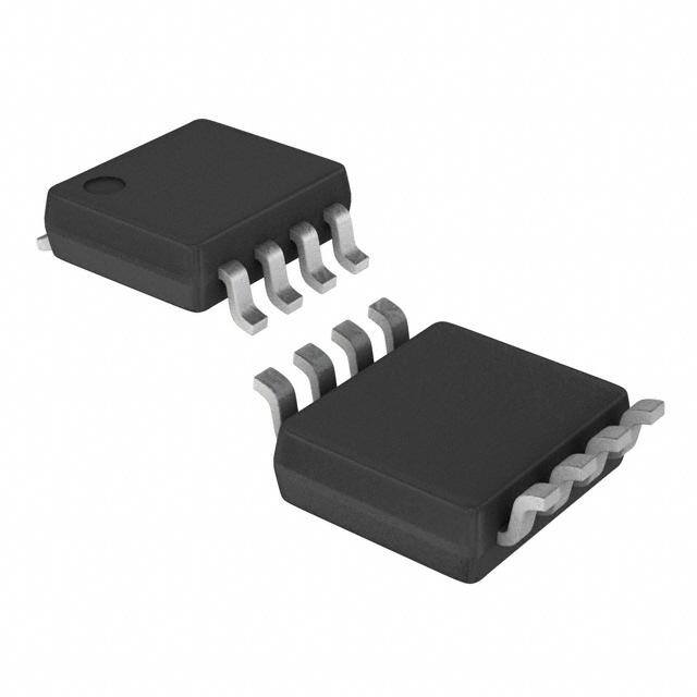
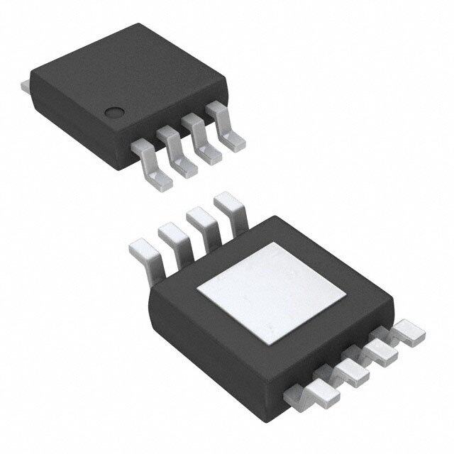
Product Order Technical Tools & Support & Reference Folder Now Documents Software Community Design UCC28C40,UCC28C41,UCC28C42,UCC28C43,UCC28C44,UCC28C45 UCC38C40,UCC38C41,UCC38C42,UCC38C43,UCC38C44,UCC38C45 SLUS458G–JULY2000–REVISEDJANUARY2017 UCCx8C4x BiCMOS Low-Power Current-Mode PWM Controller 1 Features Providing necessary features to control fixed frequency, peak current-mode power supplies, this • EnhancedReplacementforUCx84xand 1 family offers the following performance advantages. UCx84xAFamilyWithPin-to-PinCompatibility The device offers high-frequency operation up to 1 • 1-MHzOperation MHz, suitable for high speed applications. The • 50-µAStandbyCurrent,100-µAMaximum trimmed discharge current enables more precise programming of the maximum duty cycle and dead- • LowOperatingCurrentof2.3mAat52kHz time limit when compared to the UCx84x family. • Fast35-nsCycle-by-CycleOver-CurrentLimiting Reduced start-up and operating currents minimizes • ±1-APeakOutputCurrent start-up loss and low operating power consumption for improved efficiency. The device also features a • Rail-to-RailOutputSwingswith25-nsRiseand fast current-sense-to-output delay time of 35 ns for 20-nsFallTimes superior overload protection at the power switch, and • ±1%InitialTrimmed2.5-VErrorAmplifier a ±1-A peak output current capability with improved Reference rise and fall times for driving large external MOSFETs • TrimmedOscillatorDischargeCurrent directly. • NewUndervoltageLockoutVersions The UCC38C4x family is offered in 8-pin VSSOP • VSSOP-8PackageMinimizesBoardSpace (DGK),8-pinSOIC(D),and8-pinPDIP(P)packages. 2 Applications DeviceInformation(1) PARTNUMBER PACKAGE BODYSIZE(NOM) • Switch-ModePowerSupplies SOIC(8) 3.91mm×4.90mm • GeneralPurposeDC-DCorOff-LineIsolated UCC28C4x, PDIP(8) 6.35mm×9.81mm PowerConverters UCC38C4x VSSOP(8) 3.00mm×3.00mm • BoardMountPowerModules (1) For all available packages, see the orderable addendum at theendofthedatasheet. 3 Description UCCx8C4x family are high-performance, current- SimplifiedSchematic mode PWM controllers. The UCCx8C4x is an enhanced BiCMOS version with pin-for-pin VIN VOUT compatibility to the industry standard UCx84xA family and UCx84x family of PWM controllers. The BiCMOS technology offers lower power consumption to VDD OUT improve efficiency as well as faster current sense and oscillator frequency. In addition, lower startup voltage VREF CS versions of 7 V are offered as UCCx8C40 and UCC28C43 UCCx8C41 for use in battery systems. The FB UCC28C4x series is specified for operation from RT/CT –40°C to 105°C, and the UCC38C4x series is GND COMP specifiedforoperationfrom0°Cto70°C. Copyright © 2016, Texas Instruments Incorporated 1 An IMPORTANT NOTICE at the end of this data sheet addresses availability, warranty, changes, use in safety-critical applications, intellectualpropertymattersandotherimportantdisclaimers.PRODUCTIONDATA.
UCC28C40,UCC28C41,UCC28C42,UCC28C43,UCC28C44,UCC28C45 UCC38C40,UCC38C41,UCC38C42,UCC38C43,UCC38C44,UCC38C45 SLUS458G–JULY2000–REVISEDJANUARY2017 www.ti.com Table of Contents 1 Features.................................................................. 1 9 ApplicationandImplementation........................ 22 2 Applications........................................................... 1 9.1 ApplicationInformation............................................22 3 Description............................................................. 1 9.2 TypicalApplication..................................................24 4 RevisionHistory..................................................... 2 10 PowerSupplyRecommendations..................... 35 5 DeviceComparisonTable..................................... 3 11 Layout................................................................... 35 6 PinConfigurationandFunctions......................... 3 11.1 LayoutGuidelines.................................................35 11.2 LayoutExample....................................................37 7 Specifications......................................................... 4 12 DeviceandDocumentationSupport................. 38 7.1 AbsoluteMaximumRatings......................................4 7.2 ESDRatings..............................................................4 12.1 DeviceSupport......................................................38 7.3 RecommendedOperatingConditions.......................4 12.2 DocumentationSupport........................................38 7.4 ThermalInformation..................................................5 12.3 RelatedLinks........................................................38 7.5 ElectricalCharacteristics...........................................5 12.4 ReceivingNotificationofDocumentationUpdates38 7.6 TypicalCharacteristics..............................................7 12.5 CommunityResources..........................................38 12.6 Trademarks...........................................................39 8 DetailedDescription............................................ 11 12.7 ElectrostaticDischargeCaution............................39 8.1 Overview.................................................................11 12.8 Glossary................................................................39 8.2 FunctionalBlockDiagram.......................................12 13 Mechanical,Packaging,andOrderable 8.3 FeatureDescription.................................................12 Information........................................................... 39 8.4 DeviceFunctionalModes........................................21 4 Revision History NOTE:Pagenumbersforpreviousrevisionsmaydifferfrompagenumbersinthecurrentversion. ChangesfromRevisionF(August2016)toRevisionG Page • ChangedV equation.............................................................................................................................................. 26 REFLECTED • ChangedD equation. ..................................................................................................................................................... 26 MAX ChangesfromRevisionE(October2010)toRevisionF Page • AddedDeviceInformationtable,PinConfigurationandFunctionssection,Specificationssection,ESDRatingstable, DetailedDescriptionsection,ApplicationandImplementationsection,PowerSupplyRecommendationssection, Layoutsection,DeviceandDocumentationSupportsection,andMechanical,Packaging,andOrderableInformation section.................................................................................................................................................................................... 1 • AddedThermalInformationtable........................................................................................................................................... 5 ChangesfromRevisionD(December2006)toRevisionE Page • UpdatedAvailableOptionsTableheadingfromT toT =T ............................................................................................... 3 A A J • UpdatedOperatingJunctionTemperatureintheRecommendedOperatingConditionsTable,from–55to150to–40 to105...................................................................................................................................................................................... 4 2 SubmitDocumentationFeedback Copyright©2000–2017,TexasInstrumentsIncorporated ProductFolderLinks:UCC28C40 UCC28C41 UCC28C42 UCC28C43 UCC28C44 UCC28C45UCC38C40 UCC38C41 UCC38C42 UCC38C43 UCC38C44 UCC38C45
UCC28C40,UCC28C41,UCC28C42,UCC28C43,UCC28C44,UCC28C45 UCC38C40,UCC38C41,UCC38C42,UCC38C43,UCC38C44,UCC38C45 www.ti.com SLUS458G–JULY2000–REVISEDJANUARY2017 5 Device Comparison Table UVLO TURNONAT14.5V TURNONAT8.4V TURNONAT7V MAXIMUM TURNOFFAT9V TURNOFFAT7.6V TURNOFFAT6.6V TEMPERATURE(TJ) DUTY SUITABLEFOROFF-LINE SUITABLEFORDC/DC SUITABLEFORBATTERY CYCLE APPLICATIONS APPLICATIONS APPLICATIONS UCC28C42 UCC28C43 UCC28C40 –40ºCTO105ºC 100% UCC38C42 UCC38C43 UCC38C40 0ºCto70ºC UCC28C44 UCC28C45 UCC28C41 –40ºCTO105ºC 50% UCC38C44 UCC38C45 UCC38C41 0ºCto70ºC 6 Pin Configuration and Functions DandPPackages DGKPackage 8-PinSOICandPDIP 8-PinVSSOP TopView TopView COMP 1 8 VREF COMP 1 8 VREF FB 2 7 VDD FB 2 7 VDD CS 3 6 OUT CS 3 6 OUT RT/CT 4 5 GND RT/CT 4 5 GND Not to scale Not to scale PinFunctions PIN I/O DESCRIPTION NAME NO. Thispinprovidestheoutputoftheerroramplifierforcompensation.Inaddition,theCOMPpinisfrequently usedasacontrolport,byutilizingasecondary-sideerroramplifiertosendanerrorsignalacrossthe COMP 1 O secondary-primaryisolationboundarythroughanopto-isolator.Theerroramplifierisinternallycurrentlimited sotheusercancommandzerodutycyclebyexternallyforcingCOMPtoGND. Thispinistheinvertinginputtotheerroramplifier.FBisusedtocontrolthepowerconvertervoltage-feedback FB 2 I loopforstability.Thenoninvertinginputtotheerroramplifierisinternallytrimmedto2.5V±1%. Primary-sidecurrentsensepin.ThecurrentsensepinisthenoninvertinginputtothePWMcomparator. Connecttocurrentsensingresistor.Thissignaliscomparedtoasignalproportionaltotheerroramplifier CS 3 I outputvoltage.ThePWMusesthistoterminatetheOUTswitchconduction.Avoltagerampcanbeappliedto thispintorunthedevicewithavoltagemodecontrolconfiguration. Fixedfrequencyoscillatorsetpoint.Connecttimingresistor(R )toVREFandtimingcapacitor(C )toGND RT CT fromthispintosettheswitchingfrequency.Forbestperformance,keepthetimingcapacitorleadtothedevice GNDasshortanddirectaspossible.Ifpossible,useseparategroundtracesforthetimingcapacitorandall RT/CT 4 I/O otherfunctions.Theswitchingfrequency(f )oftheUCCx8C40,UCCx8C42,andUCCx8C43gatedriveis SW equaltof ;theswitchingfrequencyoftheUCCx8C41,UCCx8C44,andUCCx8C45isequaltohalfofthe OSC f . OSC GND 5 — Groundreturnpinfortheoutputdriverstageandthelogiclevelcontrollersection. Theoutputoftheon-chipdrivestage.OUTisintendedtodirectlydriveaMOSFET.TheOUTpininthe UCCx8C40,UCCx8C42,andUCCx8C43isthesamefrequencyastheoscillator,andcanoperatenear100% OUT 6 O dutycycle.IntheUCCx8C41,UCCx8C44,andUCCx8C45,thefrequencyofOUTisone-halfthatofthe oscillatorduetoaninternalTflipflop.Thislimitsthemaximumdutycycleto<50%.Peakcurrentsofupto1A aresourcedandsunkbythispin.OUTisactivelyheldlowwhenVDDisbelowtheturnonthreshold. Analogcontrollerbiasinputthatprovidespowertothedevice.TotalVDDcurrentisthesumofthequiescent VDDcurrentandtheaverageOUTcurrent.Abypasscapacitor,typically0.1µF,connecteddirectlytoGND VDD 7 I withminimaltracelength,isrequiredonthispin.Additionalcapacitanceatleast10timesgreaterthanthegate capacitanceofthemainswitchingFETusedinthedesignisalsorequiredonVDD. Copyright©2000–2017,TexasInstrumentsIncorporated SubmitDocumentationFeedback 3 ProductFolderLinks:UCC28C40 UCC28C41 UCC28C42 UCC28C43 UCC28C44 UCC28C45UCC38C40 UCC38C41 UCC38C42 UCC38C43 UCC38C44 UCC38C45
UCC28C40,UCC28C41,UCC28C42,UCC28C43,UCC28C44,UCC28C45 UCC38C40,UCC38C41,UCC38C42,UCC38C43,UCC38C44,UCC38C45 SLUS458G–JULY2000–REVISEDJANUARY2017 www.ti.com PinFunctions(continued) PIN I/O DESCRIPTION NAME NO. 5-Vreferencevoltage.VREFisusedtoprovidechargingcurrenttotheoscillatortimingcapacitorthroughthe timingresistor.ItisimportantforreferencestabilitythatVREFisbypassedtoGNDwithaceramiccapacitor VREF 8 O connectedasclosetothepinaspossible.Aminimumvalueof0.1µFceramicisrequired.AdditionalVREF bypassingisrequiredforexternalloadsonVREF. 7 Specifications 7.1 Absolute Maximum Ratings overoperatingfree-airtemperaturerange(unlessotherwisenoted)(1)(2) MIN MAX UNIT Inputvoltage VDD 20 V Inputcurrent VDD 30 mA Outputdrivecurrent(peak) ±1 A Outputenergy(capacitiveload),E 5 µJ OUT Analoginputvoltage COMP,CS,FB,RT/CT –0.3 6.3 Outputdrivervoltage OUT –0.3 20 V Referencevoltage VREF 7 Erroramplifieroutputsinkcurrent COMP 10 mA Dpackage 50 TotalpowerdissipationatT =25°C DGKpackage 120 °C/W A Ppackage 65 Leadtemperature(soldering,10s),T 300 °C LEAD Operatingjunctiontemperature,T –55 150 °C J Storagetemperature,T –65 150 °C stg (1) StressesbeyondthoselistedunderAbsoluteMaximumRatingsmaycausepermanentdamagetothedevice.Thesearestressratings only,whichdonotimplyfunctionaloperationofthedeviceattheseoranyotherconditionsbeyondthoseindicatedunderRecommended OperatingConditions.Exposuretoabsolute-maximum-ratedconditionsforextendedperiodsmayaffectdevicereliability. (2) AllvoltagesarewithrespecttoGNDpin.Currentsarepositiveintoandnegativeoutofthespecifiedterminals. 7.2 ESD Ratings VALUE UNIT Human-bodymodel(HBM),perANSI/ESDA/JEDECJS-001(1) ±2500 V Electrostaticdischarge V (ESD) Charged-devicemodel(CDM),perJEDECspecificationJESD22-C101(2) ±1500 (1) JEDECdocumentJEP155statesthat500-VHBMallowssafemanufacturingwithastandardESDcontrolprocess. (2) JEDECdocumentJEP157statesthat250-VCDMallowssafemanufacturingwithastandardESDcontrolprocess. 7.3 Recommended Operating Conditions overoperatingfree-airtemperaturerange(unlessotherwisenoted) MIN MAX UNIT V Inputvoltage 18 V VDD V Outputdrivervoltage 18 V OUT I Averageoutputdrivercurrent(1) 200 mA OUT I Referenceoutputcurrent(1) –20 mA OUT(VREF) UCC28C4x –40 105 T Operatingjunctiontemperature(1) °C J UCC38C4x 0 70 (1) TIrecommendsagainstoperatingthedeviceunderconditionsbeyondthosespecifiedinthistableforextendedperiodsoftime. 4 SubmitDocumentationFeedback Copyright©2000–2017,TexasInstrumentsIncorporated ProductFolderLinks:UCC28C40 UCC28C41 UCC28C42 UCC28C43 UCC28C44 UCC28C45UCC38C40 UCC38C41 UCC38C42 UCC38C43 UCC38C44 UCC38C45
UCC28C40,UCC28C41,UCC28C42,UCC28C43,UCC28C44,UCC28C45 UCC38C40,UCC38C41,UCC38C42,UCC38C43,UCC38C44,UCC38C45 www.ti.com SLUS458G–JULY2000–REVISEDJANUARY2017 7.4 Thermal Information UCC28C4x,UCC38C4x THERMALMETRIC(1) D(SOIC) P(PDIP) DGK(VSSOP) UNIT 8PINS 8PINS 8PINS R Junction-to-ambientthermalresistance 107.7 63.4 159.9 °C/W θJA R Junction-to-case(top)thermalresistance 52.7 57.3 53 °C/W θJC(top) R Junction-to-boardthermalresistance 48.3 40.6 80.5 °C/W θJB ψ Junction-to-topcharacterizationparameter 11.3 27.7 6.2 °C/W JT ψ Junction-to-boardcharacterizationparameter 47.8 40.5 79.1 °C/W JB (1) Formoreinformationabouttraditionalandnewthermalmetrics,seetheSemiconductorandICPackageThermalMetricsapplication report. 7.5 Electrical Characteristics V =15V(1),R =10kΩ,C =3.3nF,C =0.1µFandnoloadontheoutputs,T =–40°Cto105°CfortheUCC28C4x VDD RT CT VDD A andT =0°Cto70°CfortheUCC38C4x,T =T (unlessotherwisenoted). A J A PARAMETER TESTCONDITIONS MIN TYP MAX UNIT REFERENCE V VREFvoltage,initialaccuracy T =25°C,I =1mA 4.9 5 5.1 V VREF A OUT Lineregulation V =12Vto18V 0.2 20 mV VDD Loadregulation 1mAto20mA 3 25 mV Temperaturestability See (2) 0.2 0.4 mV/°C Totaloutputvariation See (2) 4.82 5.18 V VREFnoisevoltage 10Hzto10kHz,T =25°C,see (2) 50 µV A Longtermstability 1000hours,T =125°C,see (2) 5 25 mV A I Outputshortcircuit –30 –45 –55 mA VREF OSCILLATOR f Initialaccuracy T =25°C,see (3) 50.5 53 55 kHz OSC A Voltagestability 12V≤V ≤18V 0.2% 1% VDD Temperaturestability T toT ,see (2) 1% 2.5% A(MIN) A(MAX) Amplitude RT/CTpinpeak-to-peakvoltage 1.9 V T =25°C,V =2V,see (4) 7.7 8.4 9 A RT/CT Dischargecurrent mA V =2V,see (4) 7.2 8.4 9.5 RT/CT ERRORAMPLIFIER V Feedbackinputvoltage,initialaccuracy V =2.5V,T =25°C 2.475 2.5 2.525 V FB COMP A Feedbackinputvoltage,totalvariation V =2.5V 2.45 2.5 2.55 V COMP I Inputbiascurrent V =5V –0.1 –2 µA FB FB A Open-loopvoltagegain 2V≤V ≤4V 65 90 dB VOL OUT Unitygainbandwidth See (2) 1 1.5 MHz PSRR Powersupplyrejectionratio 12V≤V ≤18V 60 dB VDD Outputsinkcurrent V =2.7V,V =1.1V 2 14 mA FB COMP Outputsourcecurrent V =2.3V,V =5V –0.5 –1 mA FB COMP VOH High-levelCOMPvoltage V =2.7V,R =15kΩCOMPtoGND 5 6.8 V FB COMP VOL Low-levelCOMPvoltage V =2.7V,R =15kΩCOMPtoVREF 0.1 1.1 V FB COMP (1) AdjustV abovethestartthresholdbeforesettingat15.5V. VDD (2) Ensuredbydesign.Notproductiontested. (3) OutputfrequenciesoftheUCCx8C41,UCCx8C44,andtheUCCx8C45arehalftheoscillatorfrequency. (4) OscillatordischargecurrentismeasuredwithR =10kΩtoVREF. RT Copyright©2000–2017,TexasInstrumentsIncorporated SubmitDocumentationFeedback 5 ProductFolderLinks:UCC28C40 UCC28C41 UCC28C42 UCC28C43 UCC28C44 UCC28C45UCC38C40 UCC38C41 UCC38C42 UCC38C43 UCC38C44 UCC38C45
UCC28C40,UCC28C41,UCC28C42,UCC28C43,UCC28C44,UCC28C45 UCC38C40,UCC38C41,UCC38C42,UCC38C43,UCC38C44,UCC38C45 SLUS458G–JULY2000–REVISEDJANUARY2017 www.ti.com Electrical Characteristics (continued) V =15V(1),R =10kΩ,C =3.3nF,C =0.1µFandnoloadontheoutputs,T =–40°Cto105°CfortheUCC28C4x VDD RT CT VDD A andT =0°Cto70°CfortheUCC38C4x,T =T (unlessotherwisenoted). A J A PARAMETER TESTCONDITIONS MIN TYP MAX UNIT CURRENTSENSE A Gain See (5)(6) 2.85 3 3.15 V/V CS V Maximuminputsignal V <2.4V 0.9 1 1.1 V CS FB PSRR Powersupplyrejectionratio V =12Vto18V(2)(5) 70 dB VDD I Inputbiascurrent –0.1 –2 µA CS t CStooutputdelay 35 70 ns D COMPtoCSoffset V =0V 1.15 V CS OUTPUT V R pulldown I =200mA 5.5 15 Ω OUT(low) DS(on) SINK V R pullup I =200mA 10 25 Ω OUT(high) DS(on) SOURCE t RisetIme T =25°C,C =1nF 25 50 ns RISE A OUT t FalltIme T =25°C,C =1nF 20 40 ns FALL A OUT UNDERVOLTAGELOCKOUT UCCx8C42,UCCx8C44 13.5 14.5 15.5 VDD Startthreshold UCCx8C43,UCCx8C45 7.8 8.4 9 V ON UCCx8C40,UCCx8C41 6.5 7 7.5 UCCx8C42,UCCx8C44 8 9 10 VDD Minimumoperatingvoltage UCCx8C43,UCCx8C45 7 7.6 8.2 V OFF UCCx8C40,UCCx8C41 6.1 6.6 7.1 PWM UCCx8C42,UCCx8C43,UCCx8C40,V <2.4V 94% 96% FB D Maximumdutycycle MAX UCCx8C44,UCCx8C45,UCCx8C41,V <2.4V 47% 48% FB D Minimumdutycycle V >2.6V 0% MIN FB CURRENTSUPPLY I Start-upcurrent V =VDD –0.5V 50 100 µA START-UP VDD ON I Operatingsupplycurrent V =V =0V 2.3 3 mA VDD FB CS (5) ParametermeasuredattrippointoflatchwithV =0V. FB (6) GainisdefinedasA =ΔV /ΔV ,0V≤V ≤900mV CS COMP CS CS 6 SubmitDocumentationFeedback Copyright©2000–2017,TexasInstrumentsIncorporated ProductFolderLinks:UCC28C40 UCC28C41 UCC28C42 UCC28C43 UCC28C44 UCC28C45UCC38C40 UCC38C41 UCC38C42 UCC38C43 UCC38C44 UCC38C45
UCC28C40,UCC28C41,UCC28C42,UCC28C43,UCC28C44,UCC28C45 UCC38C40,UCC38C41,UCC38C42,UCC38C43,UCC38C44,UCC38C45 www.ti.com SLUS458G–JULY2000–REVISEDJANUARY2017 7.6 Typical Characteristics 1000 9.5 A kHz) nt--m 9.0 ncy ( 100 Curre ue ge 8.5 or Freq Dischar at or 8.0 Oscill 10 220 pF scillat f OSC 41247 ..n270F nn pFFF I--ODISCH 7.5 1 7.0 1 10 100 --50 --25 0 25 50 75 100 125 RRT Timing Resistance (k:) D001 TJ--Temperature--°C Figure1.OscillatorFrequencyvsTimingResistance Figure2.OscillatorDischargeCurrentvsTemperature andCapacitance 100 200 1.8 90 180 1.6 80 160 1.4 GAIN 70 140°)( 1.2 -- dB) 5600 112000Margin toCS 1.0 ain--( 40 80 Phase COMP 0.8 G 0.6 30 60 PHASE 20 MARGIN 40 0.4 10 20 0.2 0 0 0.0 1 10 100 1k 10k 100k 1M 10M --50 --25 0 25 50 75 100 125 f--Frequency--Hz TJ--Temperature--°C V =0V CS Figure3.ErrorAmplifierFrequencyResponse Figure4.COMPtoCSOffsetVoltagevsTemperature 5.05 2.55 V 5.04 -- 2.54 e g a V 5.03 olt 2.53 -- V ceVoltage 55..0012 Reference 22..5521 eferen 5.00 plifier 2.50 R 4.99 m 2.49 -- A VREF 4.98 Error 2.48 4.97 -- 2.47 EF R 4.96 EA 2.46 V 4.95 2.45 --50 --25 0 25 50 75 100 125 --50 --25 0 25 50 75 100 125 TJ--Temperature--°C TJ--Temperature--°C Figure5.ReferenceVoltagevsTemperature Figure6.ErrorAmplifierReferenceVoltagevsTemperature Copyright©2000–2017,TexasInstrumentsIncorporated SubmitDocumentationFeedback 7 ProductFolderLinks:UCC28C40 UCC28C41 UCC28C42 UCC28C43 UCC28C44 UCC28C45UCC38C40 UCC38C41 UCC38C42 UCC38C43 UCC38C44 UCC38C45
UCC28C40,UCC28C41,UCC28C42,UCC28C43,UCC28C44,UCC28C45 UCC38C40,UCC38C41,UCC38C42,UCC38C43,UCC38C44,UCC38C45 SLUS458G–JULY2000–REVISEDJANUARY2017 www.ti.com Typical Characteristics (continued) --35 200 A --m --37 nA 150 uitCurrent ----4319 Current-- 100 Circ --43 Bias 50 Short --45 Input 0 erence --47 mplifier --50 ef --49 A --RSC --51 Error --100 I --53 --S --150 A BI I --55 --200 --50 --25 0 25 50 75 100 125 --50 --25 0 25 50 75 100 125 TJ--Temperature--°C TJ--Temperature--°C Figure7.ReferenceShort-CircuitCurrentvsTemperature Figure8.ErrorAmplifierInputBiasCurrentvsTemperature 16 9.0 UVLO 15 8.8 ON 14 V 8.6 V e-- Voltage-- 1132 UOVLNO OVoltag 88..42 VLO 11 UOVFLFO UVL 8.0 U -- V--UVLO 109 VUVLO 77..86 8 7.4 7 7.2 UVLO OFF 6 7.0 --50 --25 0 25 50 75 100 125 --50 --25 0 25 50 75 100 125 TJ--Temperature--°C TJ--Temperature--°C UCCx8C42andUCCx8C44 UCCx8C43andUCCx8C45 Figure9.UndervoltageLockoutvsTemperature Figure10.UndervoltageLockoutvsTemperature 7.3 25 7.2 UVLO ON 1-nFLOAD 7.1 A 20 m --V 7.0 nt-- e e oltag 6.9 Curr 15 V y O 6.8 pl --UVLVLO 6.7 --SupDD 10 NOLOAD VU 6.6 I 6.5 5 UVLO 6.4 OFF 6.3 0 --50 --25 0 25 50 75 100 125 0k 200k 400k 600k 800k 1M TJ--Temperature--°C f--Frequency--Hz UCCx8C40andUCCx8C41 Figure11.UndervoltageLockoutvsTemperature Figure12.SupplyCurrentvsOscillatorFrequency 8 SubmitDocumentationFeedback Copyright©2000–2017,TexasInstrumentsIncorporated ProductFolderLinks:UCC28C40 UCC28C41 UCC28C42 UCC28C43 UCC28C44 UCC28C45UCC38C40 UCC38C41 UCC38C42 UCC38C43 UCC38C44 UCC38C45
UCC28C40,UCC28C41,UCC28C42,UCC28C43,UCC28C44,UCC28C45 UCC38C40,UCC38C41,UCC38C42,UCC38C43,UCC38C44,UCC38C45 www.ti.com SLUS458G–JULY2000–REVISEDJANUARY2017 Typical Characteristics (continued) 3.0 40 10%to90% 2.9 VDD=12V 35 2.8 s tr mA 2.7 e--n (1nF) -- m 30 urrent 2.6 FallTI (1tnfF) SupplyC 22..45 NOLOAD Riseand 25 I--DD 2.3 Output 20 2.2 15 2.1 2.0 10 --50 --25 0 25 50 75 100 125 --50 --25 0 25 50 75 100 125 TJ--Temperature--°C TJ--Temperature--°C Figure13.SupplyCurrentvsTemperature Figure14.OutputRiseTimeandFallTimevsTemperature 100 100 UCC38C40 UCC38C42 CT=220pF UCC38C43 90 98 % -- e --% 80 Cycl 96 Cycle Duty Duty 70 CT=1nF mum 94 xi a M 60 92 50 90 0 500 1000 1500 2000 2500 --50 --25 0 25 50 75 100 125 f--Frequency--kHz TJ--Temperature--°C Figure15.MaximumDutyCyclevsOscillatorFrequency Figure16.MaximumDutyCyclevsTemperature 50 1.10 UCC38C41 UCC38C44 s UCC38C45 V me--n 49 hold-- 1.05 TI es Fall 48 Thr d e sean Sens 1.00 Ri nt put 47 urre ut C O 46 --S_th 0.95 C V 45 0.90 --50 --25 0 25 50 75 100 125 --50 --25 0 25 50 75 100 125 TJ--Temperature--°C TJ--Temperature--°C Figure17.MaximumDutyCyclevsTemperature Figure18.CurrentSenseThresholdVoltagevsTemperature Copyright©2000–2017,TexasInstrumentsIncorporated SubmitDocumentationFeedback 9 ProductFolderLinks:UCC28C40 UCC28C41 UCC28C42 UCC28C43 UCC28C44 UCC28C45UCC38C40 UCC38C41 UCC38C42 UCC38C43 UCC38C44 UCC38C45
UCC28C40,UCC28C41,UCC28C42,UCC28C43,UCC28C44,UCC28C45 UCC38C40,UCC38C41,UCC38C42,UCC38C43,UCC38C44,UCC38C45 SLUS458G–JULY2000–REVISEDJANUARY2017 www.ti.com Typical Characteristics (continued) 70 65 s 60 n -- e m 55 Ti y a el 50 D T U O 45 o t S C 40 -- D t 35 30 --50 --25 0 25 50 75 100 125 TJ--Temperature--°C Figure19.CurrentSensetoOutputDelayTimevsTemperature 10 SubmitDocumentationFeedback Copyright©2000–2017,TexasInstrumentsIncorporated ProductFolderLinks:UCC28C40 UCC28C41 UCC28C42 UCC28C43 UCC28C44 UCC28C45UCC38C40 UCC38C41 UCC38C42 UCC38C43 UCC38C44 UCC38C45
UCC28C40,UCC28C41,UCC28C42,UCC28C43,UCC28C44,UCC28C45 UCC38C40,UCC38C41,UCC38C42,UCC38C43,UCC38C44,UCC38C45 www.ti.com SLUS458G–JULY2000–REVISEDJANUARY2017 8 Detailed Description 8.1 Overview The UCCx8C4x series of control integrated circuits provide the features necessary to implement AC-DC or DC‑to-DC fixed-frequency current-mode control schemes with a minimum number of external components. Protection circuitry includes undervoltage lockout (UVLO) and current limiting. Internally implemented circuits include a start-up current of less than 100 µA, a precision reference trimmed for accuracy at the error amplifier input, logic to ensure latched operation, a pulse-width modulation (PWM) comparator that also provides current- limit control, and an output stage designed to source or sink high-peak current. The output stage, suitable for driving N-channel MOSFETs, is low when it is in the OFF state. The oscillator contains a trimmed discharge current that enables accurate programming of the maximum duty cycle and dead time limit, making this device suitableforhigh-speedapplications. Major differences between members of this series are the UVLO thresholds, acceptable ambient temperature range, and maximum duty cycle. Typical UVLO thresholds of 14.5 V (ON) and 9 V (OFF) on the UCCx8C42 and UCCx8C44 devices make them ideally suited to off-line AC-DC applications. The corresponding typical thresholds for the UCCx8C43 and UCCx8C45 devices are 8.4 V (ON) and 7.6 V (OFF), making them ideal for use with regulated input voltages used in DC-DC applications. The UCCx8C40 and UCCx8C41 feature a start-up threshold of 7 V and a turnoff threshold of 6.6 V (OFF), which makes them suitable for battery-powered applications. The UCCx8C40, UCCx8C42, and UCCx8C43 devices operate to duty cycles approaching 100%. The UCCx8C41, UCCx8C44, and UCCx8C45 obtain a duty cycle from 0% to 50% by the addition of an internal toggle flip-flop, which blanks the output off every other clock cycle. The UCC28C4x series is specified for operationfrom–40°Cto105°C,andtheUCC38C4xseriesisspecifiedforoperationfrom0°Cto70°C. The UCC28C4x and UCC38C4x series are an enhanced replacement with pin-to-pin compatibility to the bipolar UC284x, UC384x, UC284xA, and UC384xA families. The new series offers improved performance when compared to older bipolar devices and other competitive BiCMOS devices with similar functionality. These improvements generally consist of tighter specification limits that are a subset of the older product ratings, maintaining drop-in capability. In new designs, these improvements can reduce the component count or enhance circuitperformancewhencomparedtothepreviouslyavailabledevices. Copyright©2000–2017,TexasInstrumentsIncorporated SubmitDocumentationFeedback 11 ProductFolderLinks:UCC28C40 UCC28C41 UCC28C42 UCC28C43 UCC28C44 UCC28C45UCC38C40 UCC38C41 UCC38C42 UCC38C43 UCC38C44 UCC38C45
UCC28C40,UCC28C41,UCC28C42,UCC28C43,UCC28C44,UCC28C45 UCC38C40,UCC38C41,UCC38C42,UCC38C43,UCC38C44,UCC38C45 SLUS458G–JULY2000–REVISEDJANUARY2017 www.ti.com 8.2 Functional Block Diagram VDD UVLO EN VREF 5 V VREF VREF Good Logic RT/CT Osc OUT T (NOTE) 2.5 V 2R S + E/A PWM GND FB R Latch R 1 V PWM COMP Comparator CS Copyright © 2016, Texas Instruments Incorporated Toggleflip-flopusedonlyinUCCx8C41,UCCx8C44,andUCCx8C45 8.3 Feature Description The BiCMOS design allows operation at high frequencies that were not feasible in the predecessor bipolar devices. First, the output stage has been redesigned to drive the external power switch in approximately half the time of the earlier devices. Second, the internal oscillator is more robust, with less variation as frequency increases.Thisfasteroscillatormakesthisdevicesuitableforhighspeedapplicationsandthetrimmeddischarge current enables precise programming of the maximum duty cycle and dead-time limit. In addition, the current sense to output delay has been reduced by a factor of three, to 45 ns (typical). The reduced delay times in the current sense results in superior overload protection at the power switch. The reduced start-up current of this device minimizes steady state power dissipation in the startup resistor, and the low operating current maximizes efficiency while running, increasing the total circuit efficiency, whether operating off-line, DC input, or battery operatedcircuits.Thesefeaturescombinetoprovideadevicecapableofreliable,high-frequencyoperation. Table1.ImprovedKeyParameters PARAMETER UCCx8C4x UCx84x Supplycurrentat50kHz 2.3mA 11mA Start-upcurrent 50µA 1mA Overcurrentpropagationdelay 50ns 150ns Referencevoltageaccuracy ±1% ±2% Erroramplifierreferencevoltageaccuracy ±25mV ±80mV Maximumoscillatorfrequency >1MHz 500kHz Outputrise/falltimes 25ns 50ns UVLOturnonaccuracy ±1V ±1.5V Smallestpackageoption MSOP-8 SOIC-8 12 SubmitDocumentationFeedback Copyright©2000–2017,TexasInstrumentsIncorporated ProductFolderLinks:UCC28C40 UCC28C41 UCC28C42 UCC28C43 UCC28C44 UCC28C45UCC38C40 UCC38C41 UCC38C42 UCC38C43 UCC38C44 UCC38C45
UCC28C40,UCC28C41,UCC28C42,UCC28C43,UCC28C44,UCC28C45 UCC38C40,UCC38C41,UCC38C42,UCC38C43,UCC38C44,UCC38C45 www.ti.com SLUS458G–JULY2000–REVISEDJANUARY2017 8.3.1 DetailedPinDescription 8.3.1.1 COMP TheerroramplifierintheUCCx8C4xfamilyhasaunity-gainbandwidthof1.5MHz.TheCOMPterminalcanboth sourceandsinkcurrent.Theerroramplifierisinternallycurrent-limited,sothatonecancommandzerodutycycle byexternallyforcingCOMPtoGND. 8.3.1.2 FB FB is the inverting input of the error amplifier. The noninverting input to the error amplifier is internally trimmed to 2.5 V ± 1%. FB is used to control the power converter voltage-feedback loop for stability. For best stability, keep FBleadlengthasshortaspossibleandFBstraycapacitanceassmallaspossible. 8.3.1.3 CS The UCCx8C4x current sense input connects directly to the PWM comparator. Connect CS to the MOSFET source current sense resistor. The PWM uses this signal to terminate the OUT switch conduction. A voltage ramp can be applied to this pin to run the device with a voltage mode control configuration or to add slope compensation. To prevent false triggering due to leading edge noises, an RC current sense filter may be required.Thegainofthecurrentsenseamplifieristypically3V/V. 8.3.1.4 RT/CT RT/CT is the oscillator timing pin. For fixed frequency operation, set the timing capacitor charging current by connecting a resistor from VREF to RT/CT. Set the frequency by connecting timing capacitor from RT/CT to GND. For the best performance, keep the timing capacitor lead to GND as short and direct as possible. If possible,useseparategroundtracesforthetimingcapacitorandallotherfunctions. The UCCx8C4x’s oscillator allows for operation to 1 MHz. The device uses an external resistor to set the charging current for the external capacitor, which determines the oscillator frequency. TI recommends timing resistor values from 1 kΩ to 100 kΩ and timing capacitor values from 220 pF to 4.7 nF. The UCCx8C4x oscillator is true to the curves of the original bipolar devices at lower frequencies, yet extends the frequency programmability range to at least 1 MHz. This allows the device to offer pin-to-pin capability where required, yet capable of extending the operational range to the higher frequencies. See Figure 1 for component values for settingtheoscillatorfrequency. 8.3.1.5 GND GND is the signal and power returning ground. TI recommends separating the signal return path and the high currentgatedriverpathsothatthesignalisnotaffectedbytheswitchingcurrent. 8.3.1.6 OUT The high-current output stage of the UCCx8C4x has been redesigned to drive the external power switch in approximately half the time of the earlier devices. To drive a power MOSFET directly, the totem-pole OUT driver sinks or source up to 1 A peak of current. The OUT of the UCCx8C40, UCCx8C42, and UCCx8C43 devices switch at the same frequency as the oscillator and can operate near 100% duty cycle. In the UCCx8C41, UCCx8C44,andUCCx8C45,theswitchingfrequencyofOUTisone-halfthatoftheoscillatorduetoaninternalT flip-flop.ThislimitsthemaximumdutycycleintheUCCx8C41,UCCx8C44,andUCCx8C45to <50%. The UCCx8C4x family houses unique totem pole drivers exhibiting a 10-Ω impedance to the upper rail and a 5.5‑Ω impedance to ground, typically. This reduced impedance on the low-side switch helps minimize turnoff losses at the power MOSFET, whereas the higher turnon impedance of the high-side is intended to better match the reverse recovery characteristics of many high-speed output rectifiers. Transition times, rising and falling edges,aretypically25nanosecondsand20nanoseconds,respectively,fora10%to90%changeinvoltage. A low impedance MOS structure in parallel with a bipolar transistor, or BiCMOS construction, comprises the totem-pole output structure. This more efficient utilization of silicon delivers the high peak current required along with sharp transitions and full rail-to-rail voltage swings. Furthermore, the output stage is self-biasing, active low duringunder-voltagelockouttype.WithnoVDDsupplyvoltagepresent,theoutputactivelypullslowifanattempt is made to pull the output high. This condition frequently occurs at initial power-up with a power MOSFET as the driverload. Copyright©2000–2017,TexasInstrumentsIncorporated SubmitDocumentationFeedback 13 ProductFolderLinks:UCC28C40 UCC28C41 UCC28C42 UCC28C43 UCC28C44 UCC28C45UCC38C40 UCC38C41 UCC38C42 UCC38C43 UCC38C44 UCC38C45
UCC28C40,UCC28C41,UCC28C42,UCC28C43,UCC28C44,UCC28C45 UCC38C40,UCC38C41,UCC38C42,UCC38C43,UCC38C44,UCC38C45 SLUS458G–JULY2000–REVISEDJANUARY2017 www.ti.com 8.3.1.7 VDD VDD is the power input connection for this device. In normal operation, power VDD through a current limiting resistor. The absolute maximum supply voltage is 20 V, including any transients that may be present. If this voltage is exceeded, device damage is likely. This is in contrast to the predecessor bipolar devices, which could survive up to 30 V on the input bias pin. Also, because no internal clamp is included in the device, the VDD pin must be protected from external sources which could exceed the 20 V level. If containing the start-up and bootstrap supply voltage from the auxiliary winding N below 20 V under all line and load conditions can not be A achieved, use a zener protection diode from VDD to GND. Depending on the impedance and arrangement of the bootstrap supply, this may require adding a resistor, R , in series with the auxiliary winding to limit the current VDD into the zener as shown in Figure 20. Insure that over all tolerances and temperatures, the minimum zener voltage is higher than the highest UVLO upper turnon threshold. To ensure against noise related problems, filter VDD with a ceramic bypass capacitor to GND. The VDD pin must be decoupled as close to the GND pin as possible. N N P S R START To R DBIAS NA VDD Input VDD OUT CVCC CVDDbp GND DZCLAMP 0.1 PF R CS Figure20. VDDProtection AlthoughquiescentVDDcurrentisonly100 µA,thetotalsupplycurrentishigher,dependingontheOUTcurrent. Total VDD current is the sum of quiescent VDD current and the average OUT current. Knowing the operating frequencyandtheMOSFETgatecharge(Q ),averageOUTcurrentcanbecalculatedfromEquation1. g I = Q (cid:215)f OUT g SW (1) 8.3.1.8 VREF VREF is the voltage reference for the error amplifier and also for many other internal circuits in the IC. The 5-V reference tolerance is ±1% for the UCCx8C4x family. The high-speed switching logic uses VREF as the logic power supply. The reference voltage is divided down internally to 2.5 V ±1% and connected to the error amplifier's noninverting input for accurate output voltage regulation. The reference voltage sets the internal bias currentsandthresholdsforfunctionssuchastheoscillatorupperandlowerthresholdsalongwiththeovercurrent limiting threshold. The output short-circuit current is 55 mA (maximum). To avoid device over-heating and damage, do not pull VREF to ground as a means to terminate switching. For reference stability and to prevent noise problems with high-speed switching transients, bypass VREF to GND with a ceramic capacitor close to the IC package. A minimum of 0.1-µF ceramic capacitor is required. Additional VREF bypassing is required for externalloadsonthereference.Anelectrolyticcapacitormayalsobeusedinadditiontotheceramiccapacitor. 14 SubmitDocumentationFeedback Copyright©2000–2017,TexasInstrumentsIncorporated ProductFolderLinks:UCC28C40 UCC28C41 UCC28C42 UCC28C43 UCC28C44 UCC28C45UCC38C40 UCC38C41 UCC38C42 UCC38C43 UCC38C44 UCC38C45
UCC28C40,UCC28C41,UCC28C42,UCC28C43,UCC28C44,UCC28C45 UCC38C40,UCC38C41,UCC38C42,UCC38C43,UCC38C44,UCC38C45 www.ti.com SLUS458G–JULY2000–REVISEDJANUARY2017 8.3.2 UndervoltageLockout Three sets of UVLO thresholds are available with turnon and turnoff thresholds of: (14.5 V and 9 V), (8.4 V and 7.6 V), and (7 V and 6.6 V) respectively. The first set is primarily intended for off-line and 48-V distributed power applications, where the wider hysteresis allows for lower frequency operation and longer soft-starting time of the converter. The second group of UVLO options is ideal for high frequency DC-DC converters typically running from a 12-VDC input. The third, and newest, set has been added to address battery powered and portable applications.Table2showsthemaximumdutycycleandUVLOthresholdsbydevice. Table2.UVLOOptions MAXIMUMDUTYCYCLE UVLOON UVLOOFF PARTNUMBER 100% 14.5V 9V UCCx8C42 100% 8.4V 7.6V UCCx8C43 100% 7V 6.6V UCCx8C40 50% 14.5V 9V UCCx8C44 50% 8.4V 7.6V UCCx8C45 50% 7V 6.6V UCCx8C41 During UVLO the IC draws less than 100 µA of supply current. Once crossing the turnon threshold the IC supply current increases to a maximum of 3 mA, typically 2.3 mA. This low start-up current allows the power supply designer to optimize the selection of the startup resistor value to provide a more efficient design. In applications where low component cost overrides maximum efficiency, the low run current of 2.3 mA (typical) allows the control device to run directly through the single resistor to (+) rail, rather than requiring a bootstrap winding on the power transformer, along with a rectifier. The start and run resistor for this case must also pass enough currenttoallowdrivingtheprimaryswitchingMOSFET,whichmaybeafewmilliampsinsmalldevices. < 3 mA I VDD < 100 µA VOFF VON V VDD Figure21. UVLOONandOFFProfile 8.3.3 ±1%InternalReferenceVoltage The BiCMOS internal reference of 2.5 V has an enhanced design, and uses production trim to allow initial accuracyof±1%atroomtemperatureand ±2%overthefulltemperaturerange.Thiscanbeusedtoeliminatean externalreferenceinapplicationsthatdonotrequiretheextremeaccuracyaffordedbytheadditionaldevice.This is useful for nonisolated DC-DC applications, where the control device is referenced to the same common as the output. It is also applicable in off-line designs that regulate on the primary side of the isolation boundary by lookingataprimarybiaswinding,orfromawindingontheoutputinductorofabuck-derivedcircuit. 8.3.4 CurrentSenseandOvercurrentLimit An external series resistor (R ) senses the current and converts this current into a voltage that becomes the CS input to the CS pin. The CS pin is the noninverting input to the PWM comparator. The CS input is compared to a signal proportional to the error amplifier output voltage; the gain of the current sense amplifier is typically 3 V/V. ThepeakI currentisdeterminedusingEquation2 SENSE Copyright©2000–2017,TexasInstrumentsIncorporated SubmitDocumentationFeedback 15 ProductFolderLinks:UCC28C40 UCC28C41 UCC28C42 UCC28C43 UCC28C44 UCC28C45UCC38C40 UCC38C41 UCC38C42 UCC38C43 UCC38C44 UCC38C45
UCC28C40,UCC28C41,UCC28C42,UCC28C43,UCC28C44,UCC28C45 UCC38C40,UCC38C41,UCC38C42,UCC38C43,UCC38C44,UCC38C45 SLUS458G–JULY2000–REVISEDJANUARY2017 www.ti.com V CS I = SENSE R CS (2) The typical value for V is 1 V. A small RC filter (R and C ) may be required to suppress switch transients CS CSF CSF caused by the reverse recovery of a secondary side diode or equivalent capacitive loading in addition to parasitic circuit impedances. The time constant of this filter should be considerably less than the switching period of the converter. Error Amplifier 2 R COMP R 1 V I PWM SENSE Comparator R CSF CS R C CS CSF GND Copyright © 2016, Texas Instruments Incorporated Figure22. Current-SenseCircuitSchematic Cycle-by-cycle pulse width modulation performed at the PWM comparator essentially compares the error amplifier output to the current sense input. This is not a direct volt-to-volt comparison, as the error amplifier output network incorporates two diodes in series with a resistive divider network before connecting to the PWM comparator. The two-diode drop adds an offset voltage that enables zero duty cycle to be achieved with a low amplifier output. The 2R/R resistive divider facilitates the use of a wider error amplifier output swing that can be moresymmetricallycenteredonthe2.5-Vnoninvertinginputvoltage. The 1-V zener diode associated with the PWM comparator’s input from the error amplifier is not an actual diode in the device’s design, but an indication that the maximum current sense input amplitude is 1 V (typical). When this threshold is reached, regardless of the error amplifier output voltage, cycle-by-cycle current limiting occurs, and the output pulse width is terminated within 35 ns (typical). The minimum value for this current limit threshold is 0.9 V with a 1.1-V maximum. In addition to the tolerance of this parameter, the accuracy of the current sense resistor, or current sense circuitry, must be taken into account. It is advised to factor in the worst case of primary and secondary currents when sizing the ratings and worst-case conditions in all power semiconductors and magneticcomponents. 8.3.5 Reduced-DischargeCurrentVariation The UCCx8C4x oscillator design incorporates a trimmed discharge current to accurately program maximum duty cycle and operating frequency. In its basic operation, a timing capacitor (C ) is charged by a current source, CT formed by the timing resistor (R ) connected to the device’s reference voltage (VREF). The oscillator design RT incorporates comparators to monitor the amplitude of the timing capacitor’s voltage. The exponentially shaped waveform charges up to a specific amplitude representing the oscillator’s upper threshold of 3 V. Once reached, an internal current sink to ground is turned on and the capacitor begins discharging. This discharge continues until the oscillator’s lower threshold has reached 0.7 V at which point the current sink is turned off. Next, the timingcapacitorstartschargingagainandanewswitchingcyclebegins. 16 SubmitDocumentationFeedback Copyright©2000–2017,TexasInstrumentsIncorporated ProductFolderLinks:UCC28C40 UCC28C41 UCC28C42 UCC28C43 UCC28C44 UCC28C45UCC38C40 UCC38C41 UCC38C42 UCC38C43 UCC38C44 UCC38C45
UCC28C40,UCC28C41,UCC28C42,UCC28C43,UCC28C44,UCC28C45 UCC38C40,UCC38C41,UCC38C42,UCC38C43,UCC38C44,UCC38C45 www.ti.com SLUS458G–JULY2000–REVISEDJANUARY2017 VDD ON VDD VREF OFF R RT CCT RT/CT CCT t ON GND t OFF 8.4 mA t PERIOD Copyright © 2016, Texas Instruments Incorporated Figure23. OscillatorCircuit While the device is discharging the timing capacitor, resistor R is also still trying to charge C . It is the exact RT CT ratio of these two currents, the discharging versus the charging current, which specifies the maximum duty cycle. During the discharge time of C , the device’s output is always off. This represents an ensured minimum off time CT of the switch, commonly referred to as dead-time. To program an accurate maximum duty cycle, use the information provided in Figure 15 for maximum duty cycle versus oscillator frequency. Any number of maximum duty cycles can be programmed for a given frequency by adjusting the values of R and C . Once R is RT CT RT selected, the oscillator timing capacitor can be found using the curves in Figure 1. However, because resistors are available in more precise increments, typically 1%, and capacitors are only available in 5% accuracy, it might bemorepracticaltoselecttheclosestcapacitorvaluefirstandthencalculatethetimingresistorvaluenext. 8.3.6 OscillatorSynchronization Synchronization is best achieved by forcing the timing capacitor voltage above the oscillator's internal upper threshold. A small resistor is placed in series with C to GND. This resistor serves as the input for the sync CT pulse which raises the C voltage above the oscillator’s internal upper threshold. The PWM is allowed to run at CT the frequency set by R and C until the sync pulse appears. This scheme offers several advantages including RT CT having the local ramp available for slope compensation. The UCCx8C4x oscillator must be set to a lower frequencythanthesyncpulsestream,typically20percentwitha0.5-Vpulseappliedacrosstheresistor. Copyright©2000–2017,TexasInstrumentsIncorporated SubmitDocumentationFeedback 17 ProductFolderLinks:UCC28C40 UCC28C41 UCC28C42 UCC28C43 UCC28C44 UCC28C45UCC38C40 UCC38C41 UCC38C42 UCC38C43 UCC38C44 UCC38C45
UCC28C40,UCC28C41,UCC28C42,UCC28C43,UCC28C44,UCC28C45 UCC38C40,UCC38C41,UCC38C42,UCC38C43,UCC38C44,UCC38C45 SLUS458G–JULY2000–REVISEDJANUARY2017 www.ti.com VREF R RT C + SYNC CT CCT RT/CT SYNC SYNC 50 (cid:13)(cid:3) GND C CT Copyright © 2016, Texas Instruments Incorporated Figure24. OscillatorSynchronizationCircuit 8.3.7 SoftStart Soft start is the technique to gradually power up the converter in a well-controlled fashion by slowly increasing the effective duty cycle starting at zero and gradually rising. Following start-up of the PWM, the error amplifier inverting input is low, commanding the error amplifier’s output to go high. The output stage of the amplifier can source1mAtypically,whichisenoughtodrivemosthighimpedancecompensationnetworks,butnotenoughfor driving large loads quickly. Soft start is achieved by charging a fairly large value, >1-µF, capacitor (C ) SS connectedtotheerroramplifieroutputthroughaPNPtransistorasshowninFigure25 VREF R SS COMP Z F 2N2907 + C SS FB Z I To VOUT Figure25. Soft-StartImplementation The limited charging current of the amplifier into the capacitor translates into a dv/dt limitation on the error amplifier output. This directly corresponds to some maximum rate of change of primary current in a current mode controlled system as one of the PWM comparator’s inputs gradually rises. The values of R and C must be SS SS selected to bring the COMP pin up at a controlled rate, limiting the peak current supplied by the power stage. After the soft-start interval is complete, the capacitor continues to charge to VREF, effectively removing the PNP transistor from the circuit consideration. Soft start performs a different, frequently preferred function in current modecontrolledsystemsthanitdoesinvoltagemodecontrol.Incurrentmode,softstartcontrolstherisingofthe peak switch current. In voltage mode control, soft start gradually widens the duty cycle, regardless of the primary currentorrateoframp-up. 18 SubmitDocumentationFeedback Copyright©2000–2017,TexasInstrumentsIncorporated ProductFolderLinks:UCC28C40 UCC28C41 UCC28C42 UCC28C43 UCC28C44 UCC28C45UCC38C40 UCC38C41 UCC38C42 UCC38C43 UCC38C44 UCC38C45
UCC28C40,UCC28C41,UCC28C42,UCC28C43,UCC28C44,UCC28C45 UCC38C40,UCC38C41,UCC38C42,UCC38C43,UCC38C44,UCC38C45 www.ti.com SLUS458G–JULY2000–REVISEDJANUARY2017 ThepurposeoftheresistorR anddiodeistotakethesoft-startcapacitoroutoftheerroramplifier’spathduring SS normaloperation,oncesoftstartiscompleteandthecapacitorisfullycharged.Theoptionaldiodeinparallelwith the resistor forces a soft start each time the PWM goes through UVLO condition that forces VREF to go low. Without the diode, the capacitor remains charged during a brief loss of supply or brown-out, and no soft start is enableduponre-applicationofVDD. 8.3.8 EnableandDisable There are a few ways to enable or disable the UCCx8C4x devices, depending on which type of restart is required. The two basic techniques use external transistors to either pull the error amplifier output low (< 2 V ) BE or pull the current sense input high (> 1.1 V). Application of the disable signal causes the output of the PWM comparator to be high. The PWM latch is reset dominant so that the output remains low until the next clock cycle after the shutdown condition at the COMP or CS pin is removed. Another choice for restart without a soft start is to pull the current sense input above the cycle-by-cycle current limiting threshold. A logic level P-channel FET fromthereferencevoltagetothecurrentsenseinputcanbeused. COMP DISABLE Figure26. DisableCircuit 8.3.9 SlopeCompensation Withcurrentmodecontrol,slopecompensationisrequiredtostabilizetheoverallloopwithdutycyclesexceeding 50%. Although not required, slope compensation also improves stability in applications using below a 50% maximum duty cycle. Slope compensation is introduced by injecting a portion of the oscillator waveform to the actual sensed primary current. The two signals are summed together at the current sense input (CS) connection at the filter capacitor. To minimize loading on the oscillator, it is best to buffer the timing capacitor waveform with asmalltransistorwhosecollectorisconnectedtothereferencevoltage. Copyright©2000–2017,TexasInstrumentsIncorporated SubmitDocumentationFeedback 19 ProductFolderLinks:UCC28C40 UCC28C41 UCC28C42 UCC28C43 UCC28C44 UCC28C45UCC38C40 UCC38C41 UCC38C42 UCC38C43 UCC38C44 UCC38C45
UCC28C40,UCC28C41,UCC28C42,UCC28C43,UCC28C44,UCC28C45 UCC38C40,UCC38C41,UCC38C42,UCC38C43,UCC38C44,UCC38C45 SLUS458G–JULY2000–REVISEDJANUARY2017 www.ti.com VREF 0.1 µF R RT RT/CT C CT R RAMP I R SENSE CSF CS R C CS CSF Copyright © 2016, Texas Instruments Incorporated Figure27. SlopeCompensationCircuit 8.3.10 VoltageMode In certain applications, voltage mode control may be a preferred control strategy for a variety of reasons. Voltage mode control is easily executable with any current mode controller, especially the UCCx8C4x family members. Implementation requires generating a 0-V to 0.9-V sawtooth shaped signal to input to the current sense pin (CS) which is also one input to the PWM comparator. This is compared to the divided down error amplifier output voltage at the other input of the PWM comparator. As the error amplifier output is varied, it intersects the sawtooth waveform at different points in time, thereby generating different pulse widths. This is a straightforward methodoflinearlygeneratingapulsewhosewidthisproportionaltotheerrorvoltage. Implementation of voltage mode control is possible by using a fraction of the oscillator timing capacitor (C ) CT waveform. This can be divided down and fed to the current sense pin as shown in Figure 28. The oscillator timing components must be selected to approximate as close to a linear sawtooth waveform as possible. Although exponentially charged, large values of timing resistance and small values of timing capacitance help approximateamorelinearshapedwaveform.Asmalltransistorisusedtobuffertheoscillatortimingcomponents from the loading of the resistive divider network. Due to the offset of the oscillator’s lower timing threshold, a DC blockingcapacitorisadded. 20 SubmitDocumentationFeedback Copyright©2000–2017,TexasInstrumentsIncorporated ProductFolderLinks:UCC28C40 UCC28C41 UCC28C42 UCC28C43 UCC28C44 UCC28C45UCC38C40 UCC38C41 UCC38C42 UCC38C43 UCC38C44 UCC38C45
UCC28C40,UCC28C41,UCC28C42,UCC28C43,UCC28C44,UCC28C45 UCC38C40,UCC38C41,UCC38C42,UCC38C43,UCC38C44,UCC38C45 www.ti.com SLUS458G–JULY2000–REVISEDJANUARY2017 VREF R RT 2N2222 RT/CT CS C CT Figure28. CurrentModePWMUsedasaVoltageModePWM 8.4 Device Functional Modes 8.4.1 NormalOperation During normal operating mode, the controller can be used in peak current mode or voltage mode control. When the converter is operating in peak current mode, the controller regulates the converter's peak current and duty cycle. When used in voltage mode control, the controller regulates the power converter's duty cycle. The regulation of the system's peak current and duty cycle can be achieved with the use of the integrated error amplifierandexternalfeedbackcircuitry. 8.4.2 UVLOMode During the system start-up, VDD voltage starts to rise from 0 V. Before the VDD voltage reaches its corresponding turnon threshold, the IC is operating in UVLO mode. In this mode, the VREF pin voltage is not generated. When VDD is above 1 V and below the turnon threshold, the VREF pin is actively pulled low. This way, VREF can be used as a logic signal to indicate UVLO mode. If the bias voltage to VDD drops below the UVLO-OFF threshold, the PWM switching stops and VREF returns to 0 V. The device can be restarted by applyingavoltagegreaterthantheUVLO-ONthresholdtotheVDDpin. Copyright©2000–2017,TexasInstrumentsIncorporated SubmitDocumentationFeedback 21 ProductFolderLinks:UCC28C40 UCC28C41 UCC28C42 UCC28C43 UCC28C44 UCC28C45UCC38C40 UCC38C41 UCC38C42 UCC38C43 UCC38C44 UCC38C45
UCC28C40,UCC28C41,UCC28C42,UCC28C43,UCC28C44,UCC28C45 UCC38C40,UCC38C41,UCC38C42,UCC38C43,UCC38C44,UCC38C45 SLUS458G–JULY2000–REVISEDJANUARY2017 www.ti.com 9 Application and Implementation NOTE Information in the following applications sections is not part of the TI component specification, and TI does not warrant its accuracy or completeness. TI’s customers are responsible for determining suitability of components for their purposes. Customers should validateandtesttheirdesignimplementationtoconfirmsystemfunctionality. 9.1 Application Information The UCCx8C4x controllers are peak current mode pulse width modulators. These controllers have an onboard amplifier and can be used in isolated and nonisolated power supply designs. There is an onboard totem pole gatedrivercapableofdelivering1Aofpeakcurrent.Thisisahigh-speedPWMcapableofoperatingatswitching frequenciesupto1MHz.Figure29showsatypicaloff-lineapplication. D50 F1 12V T1 OUT R10 100 VEAAMCCI I–Fnip2ltu4et0r VAC + BR1 R11 C12 CD32 D51 C52 L50 R56 C55 Required C1A C18 5V R12 OUT RT1 C53 C54 D6 R55 C5 SEC COMMON R6 R50 UCC38C44 R16 IC2 1 COMP REF 8 Q1 2 FB VCC 7 IC2 C13 C50 R52 R53 3 CS OUT 6 4 RT/CT GND 5 R50 C51 K IC3 A R R54 Copyright © 2016,Texas Instruments Incorporated Figure29. TypicalOff-LineApplication Figure 30 shows a forward converter with synchronous rectification. This application provides 48 V to 3.3 V at 10 A with over 85% efficiency, and uses the UCC38C42 as the secondary-side controller and UCC3961 as the primary-sidestartupcontroldevice. 22 SubmitDocumentationFeedback Copyright©2000–2017,TexasInstrumentsIncorporated ProductFolderLinks:UCC28C40 UCC28C41 UCC28C42 UCC28C43 UCC28C44 UCC28C45UCC38C40 UCC38C41 UCC38C42 UCC38C43 UCC38C44 UCC38C45
UCC28C40,UCC28C41,UCC28C42,UCC28C43,UCC28C44,UCC28C45 UCC38C40,UCC38C41,UCC38C42,UCC38C43,UCC38C44,UCC38C45 www.ti.com SLUS458G–JULY2000–REVISEDJANUARY2017 L1 4.7uH 3r3V C2 C18 1nF T1 4700pF + R20 C17 Q4 C21 VinP 10Rk7 D2 10 4700pF R2110 47C0u1F9 4C7200uF + 0.1uF Q3 PWRGND R1 32.4k C25 R27 0.047uF R26 4.7 + 4.7 C1 D1 R2 470uF 1.2k Q1 R4 1.5k R5 D5 R19 76.8k 20 BAR74 R3 2.4k VinN D3 R28 TPS2U8342 R8 R9 BAR74 100 1 IN BOOT 8 5.1k 0.33 2 7 U1 PGND HIDR 1 OVS UVS 14 R6 3 DT BTLO 6 2Cu2F6 C3 10nF 2 SD UCC3961 ST 13 Q2 4.7 4.7Cn2F2 R40223 4 VCC LODR 5 3 12 SS VDD C4 R10 0.22uF 4 FB OUT 11 C9 1k R16 21.5k C24 C8 0.1uF C23 680pF 0.1uF 5 RT PGND 10 1uF 1 U2 8 C13 46.R4k11 6 REF CS 9 R201k7 C51.66nF 2 COMP REF 7 0.22uF R10202 FB VCC C5 7 8 0.1uF AGND VS C6 R5105k 3 CS UCC38C4x OUT 6 C14 D6 +C15 C7 470pF 4 5 1uF 1uF RT/CT GND 100pF R24 C12 BZX84C15LT1 20k 3300pF R14 R18 20k40% 7.5k 1 T2 3 C11 R12 C10 R25 1500pF 200 R13 2.7nF 20k 2 4 300 Copyright © 2016,Texas Instruments Incorporated Figure30. ForwardConverterwithSynchronousRectificationUsingtheUCC38C42astheSecondary-SideController Copyright©2000–2017,TexasInstrumentsIncorporated SubmitDocumentationFeedback 23 ProductFolderLinks:UCC28C40 UCC28C41 UCC28C42 UCC28C43 UCC28C44 UCC28C45UCC38C40 UCC38C41 UCC38C42 UCC38C43 UCC38C44 UCC38C45
UCC28C40,UCC28C41,UCC28C42,UCC28C43,UCC28C44,UCC28C45 UCC38C40,UCC38C41,UCC38C42,UCC38C43,UCC38C44,UCC38C45 SLUS458G–JULY2000–REVISEDJANUARY2017 www.ti.com 9.2 Typical Application A typical application for the UCC28C42 in an off-line flyback converter is shown in Figure 31. The UCC28C42 uses an inner current control loop that contains a small current sense resistor which senses the primary inductor current ramp. This current sense resistor transforms the inductor current waveform to a voltage signal that is input directly into the primary side PWM comparator. This inner loop determines the response to input voltage changes. An outer voltage control loop involves comparing a portion of the output voltage to a reference voltage at the input of an error amplifier. When used in an off-line isolated application, the voltage feedback of the isolated output is accomplished using a secondary-side error amplifier and adjustable voltage reference, such as the TL431. The error signal crosses the primary to secondary isolation boundary using an opto-isolator whose collector is connected to the VREF pin and the emitter is connected to FB. The outer voltage control loop determinestheresponsetoloadchanges. DCLAMP VtINo 2=6 855 V VAACC ~ C1S0N nUFB R50SN kU(cid:13)B(cid:3) DOUT – DBRIDGE + CSS ~ C1I8N0 µF R4S2T0Ak RT(cid:13)(cid:3) DBIAS R2V2D (cid:13)D(cid:3) NP NS 2C20O0UT µF V41O 2AU VT, NA RSS CVDD LP=1.5 mH 120 µF NP:NS = 10 NP:NA = 10 UCC28C42 RCOMPp CCOMPp 1 COMP VREF 8 10 k(cid:13)(cid:3) 10 nF 2 FB VDD 7 RG RRT 3 CS OUT 6 10 (cid:13)(cid:3) 15.4 k(cid:13)(cid:3) QSW 4 RT/CT GND 5 DZ CVDDbp CVREF RBLEEDER RCS CRAMP C1C0T00 pF RCSF 18 V 0.1 µF 1 µF 10 k(cid:13)(cid:3) 0.75 (cid:13)(cid:3) 1R.3L EkD(cid:13)(cid:3) 1R kT(cid:13)Lb(cid:3)ias 10 nF 3.8 k(cid:13)(cid:3) RRAMP 24.9 k(cid:13)(cid:3) OPTO- 10 V CCSF Not PRoPpulated COUPLER 9R.F5BU3 k(cid:13)(cid:3) 100 pF RFBG 4.99 k(cid:13)(cid:3) RCOMPz CCOMPz 88.7 k(cid:13)(cid:3)0.01 µF ROPTO 1 k(cid:13)(cid:3) TL431 RFBB 2.49 k(cid:13)(cid:3) Copyright © 2016, Texas Instruments Incorporated Figure31. TypicalApplicationDesignSchematic 24 SubmitDocumentationFeedback Copyright©2000–2017,TexasInstrumentsIncorporated ProductFolderLinks:UCC28C40 UCC28C41 UCC28C42 UCC28C43 UCC28C44 UCC28C45UCC38C40 UCC38C41 UCC38C42 UCC38C43 UCC38C44 UCC38C45
UCC28C40,UCC28C41,UCC28C42,UCC28C43,UCC28C44,UCC28C45 UCC38C40,UCC38C41,UCC38C42,UCC38C43,UCC38C44,UCC38C45 www.ti.com SLUS458G–JULY2000–REVISEDJANUARY2017 Typical Application (continued) 9.2.1 DesignRequirements Table 3 shows a typical set of performance requirements for an off-line flyback converter capable of providing 48 W at 12-V output voltage from a universal AC input. The design uses peak primary current control in a continuouscurrentmodePWMconverter. Table3.DesignParameters PARAMETER TESTCONDITIONS MIN NOM MAX UNIT V InputVoltage 85 115/230 265 V IN RMS f LineFrequency 47 50/60 63 Hz LINE V OutputVoltage I ≤I ≤I 11.75 12 12.25 V OUT VOUT(min) VOUT VOUT(max) V OutputRippleVoltage I ≤I ≤I 100 mVpp RIPPLE VOUT(min) VOUT VOUT(max) I OutputCurrent 0 4 A VOUT f SwitchingFrequency 110 kHz SW η Efficiency 85% 9.2.2 DetailedDesignProcedure This procedure outlines the steps to design an off-line universal input continuous current mode (CCM) flyback converterusingtheUCC28C42.SeeFigure31forcomponentnamesreferredtointhedesignprocedure. 9.2.2.1 InputBulkCapacitorandMinimumBulkVoltage Bulk capacitance may consist of one or more capacitors connected in parallel, often with some inductance between them to suppress differential-mode conducted noise. The value of the input capacitor sets the minimum bulk voltage; setting the bulk voltage lower by using minimal input capacitance results in higher peak primary currents leading to more stress on the MOSFET switch, the transformer, and the output capacitors. Setting the bulk voltage higher by using a larger input capacitor results in higher peak current from the input source and the capacitor itself is physically larger. Compromising between size and component stresses determines the acceptable minimum input voltage. The total required value for the primary-side bulk capacitance (C ) is IN selected based upon the power level of the converter (P ), the efficiency target (η), the minimum input voltage OUT (V ),andischosentomaintainanacceptableminimumbulkvoltagelevel(V ),usingEquation3. IN(min) BULK(min) 1 VBULK(min) 2(cid:215)P (cid:215) 0.25+ (cid:215)arcsin IN F N F(cid:190)2(cid:215)V GG C = IN(min) IN k2(cid:215)V2 FV2 o(cid:215)f IN(min) BULK(min) LINE(min) where • V istheRMSvalueoftheminimumACinputvoltage(85VRMS)whoseminimumlinefrequencyis IN(min) denotedasf ,equalto47Hz (3) LINE(min) Based on Equation 3, to achieve a minimum bulk voltage of 75 V, assuming 85% converter efficiency, the bulk capacitor must be larger than 126 µF; 180 µF was chosen for the design, taking into consideration component tolerancesandefficiencyestimation. 9.2.2.2 TransformerTurnsRatioandMaximumDutyCycle The transformer design starts with selecting a suitable switching frequency for the given application. The UCC28C42 is capable of switching up to 1 MHz but considerations such as overall converter size, switching losses, core loss, system compatibility, and interference with communication frequency bands generally determine an optimum frequency that should be used. For this off-line converter, the switching frequency (f ) is SW selected to be 110 kHz as a compromise to minimize the transformer size and the EMI filter size, and still have acceptablelosses. The transformer primary to secondary turns ratio (N ) can be selected based on the desired MOSFET voltage PS rating and the secondary diode voltage rating. Because the maximum input voltage is 265 VRMS, the peak bulk inputvoltagecanbecalculatedasshowninEquation4. Copyright©2000–2017,TexasInstrumentsIncorporated SubmitDocumentationFeedback 25 ProductFolderLinks:UCC28C40 UCC28C41 UCC28C42 UCC28C43 UCC28C44 UCC28C45UCC38C40 UCC38C41 UCC38C42 UCC38C43 UCC38C44 UCC38C45
UCC28C40,UCC28C41,UCC28C42,UCC28C43,UCC28C44,UCC28C45 UCC38C40,UCC38C41,UCC38C42,UCC38C43,UCC38C44,UCC38C45 SLUS458G–JULY2000–REVISEDJANUARY2017 www.ti.com V = (cid:190)2(cid:215)V N 375 V BULK(max) IN(max) (4) To minimize the cost of the system, a readily available 650V MOSFET is selected. Derating the maximum voltage stress on the drain to 80% of its rated value and allowing for a leakage inductance voltage spike of up to 30% of the maximum bulk input voltage, the reflected output voltage must be less than 130 V as shown in Equation5. (cid:11) (cid:12) V 0.8u V (cid:16)1.3uV 130.2V REFLECTED DS(rated) BULK(max) (5) Themaximumprimarytosecondarytransformerturnsratio(N )fora12Voutputcanbeselectedas PS V REFLECTED N = = 10.85 PS V OUT (6) AturnsratioofN =10isusedinthedesignexample. PS The auxiliary winding is used to supply bias voltage to the UCC28C42. Maintaining the bias voltage above the VDD minimum operating voltage after turnon is required for stable operation. The minimum VDD operating voltage for the UCC28C42 version of the controller is 10 V. The auxiliary winding is selected to support a 12 V bias voltage so that it is above the minimum operating level but still keeps the losses low in the IC. The primary toauxiliaryturnsratio(N )canbecalculatedfromEquation7: PA V OUT N = N (cid:215) = 10 PA PS V BIAS (7) Theoutputdiodeexperiencesavoltagestressthatisequaltotheoutputvoltageplusthereflectedinputvoltage: V V = BULK:max; +V = 49.5 V DIODE N OUT PS (8) TI recommends a Schottky diode with a rated blocking voltage greater than 60 V to allow for voltage spikes due toringing.Theforwardvoltagedrop(V )ofthisdiodeisestimatedtobeequalto0.6V F To avoid high peak currents, the flyback converter in this design operates in continuous conduction mode. Once N is determined, the maximum duty cycle (D ) can be calculated using the transfer function for a CCM PS MAX flybackconverter: V +V 1 D OUT F = (cid:215) MAX V lN p l1 D p BULK:min; PS F MAX (9) N u(cid:11)V (cid:14)V (cid:12) D PS OUT F 0.627 MAX V (cid:14)N u(cid:11)V (cid:14)V (cid:12) BULK(min) PS OUT F (10) Because the maximum duty cycle exceeds 50%, and the design is an off-line (AC-input) application, the UCC28C42isbestsuitedforthisapplication. 9.2.2.3 TransformerInductanceandPeakCurrents For this design example, the transformer magnetizing inductance is selected based upon the CCM condition. An inductance value that allows the converter to stay in CCM over a wider operating range before transitioning into discontinuous current mode is used to minimize losses due to otherwise high currents and also to decrease the output ripple. The design of the transformer in this example sizes the inductance so the converter enters CCM operationatapproximately10%loadandminimumbulkvoltagetominimizeoutputripple. Theinductor(L )foraCCMflybackcanbecalculatedusingEquation11. P V 2 (cid:215) NPS (cid:215)VOUT 2 1 k BULK:min;o lV +N (cid:215)V p L = (cid:215) BULK:min; PS OUT P 2 0.1(cid:215)P (cid:215)f IN SW where • P isestimatedbydividingthemaximumoutputpower(P )bythetargetefficiency(η) IN OUT • f istheswitchingfrequencyoftheconverter (11) SW 26 SubmitDocumentationFeedback Copyright©2000–2017,TexasInstrumentsIncorporated ProductFolderLinks:UCC28C40 UCC28C41 UCC28C42 UCC28C43 UCC28C44 UCC28C45UCC38C40 UCC38C41 UCC38C42 UCC38C43 UCC38C44 UCC38C45
UCC28C40,UCC28C41,UCC28C42,UCC28C43,UCC28C44,UCC28C45 UCC38C40,UCC38C41,UCC38C42,UCC38C43,UCC38C44,UCC38C45 www.ti.com SLUS458G–JULY2000–REVISEDJANUARY2017 For the UCC28C42 the switching frequency is equal to the oscillator frequency and is set to 110 kHz. Selecting f to be 110 kHz provides a good compromise between size of magnetics, switching losses, and places the first SW harmonic below the 150-kHz lower limit of EN55022. Therefore, the transformer inductance must be approximately1.8mH.A1.5mHinductanceischosenasthemagnetizinginductance,L ,valueforthisdesign. P Based on calculated inductor value and the switching frequency, the current stress of the MOSFET and output diodecanbecalculated. Thepeakcurrentintheprimary-sideMOSFETofaCCMflybackcanbecalculatedasshowninEquation12. N (cid:215)V PS OUT P V V +:N (cid:215)V ; I = IN + BULK(min)(cid:215) BULK:min; PS OUT PKMOSFET N (cid:215)V 2(cid:215)L f V (cid:215) PS OUT m SW BULK:min; V +:N (cid:215)V ; n r BULK:min; PS OUT (12) The MOSFET peak current is 1.36 A. The RMS current of the MOSFET is calculated to be 0.97 A as shown in Equation13.Therefore,IRFB9N65Aisselectedtobeusedastheprimary-sideswitch. D 3 V 2 D 2 (cid:215)I (cid:215)V I = MAX (cid:215) BULK(min) MAX PKMOSFET BULK(min) + D (cid:215)I 2 RMSMOSFET ¤ 3 l LP (cid:215)fSW p FF LP (cid:215)fSW G k MAX PKMOSFET o (13) TheoutputdiodepeakcurrentisequaltotheMOSFETpeakcurrentreflectedtothesecondaryside. I = N (cid:215)I = 13.634 A PKDIODE PS PKMOSFET (14) The diode average current is equal to the total output current (4 A) combined with a required 60-V rating and 13.6-Apeakcurrentrequirement,a48CTQ060-1isselectedfortheoutputdiode. 9.2.2.4 OutputCapacitor The total output capacitance is selected based upon the output voltage ripple requirement. In this design, 0.1% voltage ripple is assumed. Based on the 0.1% ripple requirement, the capacitor value can be selected using Equation15. N (cid:215)V I (cid:215) PS OUT OUT V +N (cid:215)V C R BULK:min; PS OUT = 1865 JF OUT 0.001(cid:215)V (cid:215)f OUT SW (15) Todesignfordevicetolerances,a2200-µFcapacitorwasselected. 9.2.2.5 CurrentSensingNetwork The current sensing network consists of the primary-side current sensing resistor (R ), filtering components CS R and C , and optional R . Typically, the direct current sense signal contains a large amplitude leading CSF CSF P edge spike associated with the turnon of the main power MOSFET, reverse recovery of the output rectifier, and other factors including charging and discharging of parasitic capacitances. Therefore, C and R form a low- CSF CSF pass filter that provides immunity to suppress the leading edge spike. For this converter, C is chosen to be CSF 100pF. Without R , R sets the maximum peak current in the transformer primary based on the maximum amplitude of P CS the CS pin, which is specified to be 1 V. To achieve 1.36-A primary side peak current, a 0.75-Ω resistor is chosenforR . CS The high current sense threshold of CS helps to provide better noise immunity to the system but also results in higher losses in the current sense resistor. These current sense losses can be minimized by injecting an offset voltage into the current sense signal using R . R and R form a resistor divider network from the current P P CSF sense signal to the device’s reference voltage (V ) which adds an offset to the current sense voltage. This VREF technique still achieves current mode control with cycle-by-cycle over-current protection. To calculate required offsetvalue(V ),useEquation16. OFFSET R V = CSF (cid:215)V OFFSET R +R REF CSF P (16) Copyright©2000–2017,TexasInstrumentsIncorporated SubmitDocumentationFeedback 27 ProductFolderLinks:UCC28C40 UCC28C41 UCC28C42 UCC28C43 UCC28C44 UCC28C45UCC38C40 UCC38C41 UCC38C42 UCC38C43 UCC38C44 UCC38C45
UCC28C40,UCC28C41,UCC28C42,UCC28C43,UCC28C44,UCC28C45 UCC38C40,UCC38C41,UCC38C42,UCC38C43,UCC38C44,UCC38C45 SLUS458G–JULY2000–REVISEDJANUARY2017 www.ti.com OnceR isadded,adjusttheR accordingly. P CS 9.2.2.6 GateDriveResistor R is the gate driver resistor for the power switch (Q ). The selection of this resistor value must be done in G SW conjunction with EMI compliance testing and efficiency testing. Using a larger resistor value for R slows down G the turnon and turnoff of the MOSFET. A slower switching speed reduces EMI but also increases the switching loss. A tradeoff between switching loss and EMI performance must be carefully performed. For this design, a 10‑Ωresistorwaschosenforthegatedriveresistor. 9.2.2.7 VREFCapacitor A precision 5-V reference voltage performs several important functions. The reference voltage is divided down internally to 2.5 V and connected to the error amplifier’s noninverting input for accurate output voltage regulation. Other duties of the reference voltage are to set internal bias currents and thresholds for functions such as the oscillator upper and lower thresholds. Therefore, the reference voltage must be bypassed with a ceramic capacitor. A 1-µF, 16-V ceramic capacitor was selected for this converter. Placement of this capacitor on the physicalprinted-circuitboardlayoutmustbeascloseaspossibletotherespectiveVREFandGNDpins. 9.2.2.8 RT/CT The internal oscillator uses a timing capacitor (C ) and a timing resistor (R ) to program the oscillator CT RT frequency and maximum duty cycle. The operating frequency can be programmed based the curves in Figure 1, where the timing resistor can be found once the timing capacitor is selected. It is best for the timing capacitor to have a flat temperature coefficient, typical of most COG or NPO type capacitors. For this converter, 15.4 kΩ and 1000pFwereselectedforR andC tooperateat110-kHzswitching. RT CT 9.2.2.9 Start-UpCircuit At start-up, the IC gets its power directly from the high-voltage bulk, through a high-voltage resistor (R ). The START selectionofthestart-upresistoristhetradeoffbetweenpowerlossandstart-uptime.Thecurrentflowingthrough R at the minimum input voltage must be higher than the VDD current under UVLO conditions (100 µA at its START maximum value). A resistance of 420-kΩ was chosen for R , providing 250 µA of start-up current at low-line START conditions.Thestart-upresistorisphysicallycomprisedoftwo210-kΩresistorsinseriestomeetthehighvoltage requirementsandpowerratingathigh-line. After VDD is charged up above the UVLO-ON threshold, the UCC28C42 starts to consume full operating current. The VDD capacitor is required to provide enough energy to prevent its voltage from dropping below the UVLO- OFF threshold during start-up, before the output is able to reach its regulated level. A large bulk capacitance would hold more energy but would result in slower start-up time. In this design, a 120-µF capacitor is chosen to provide enough energy and maintain a start-up time of approximately 7 seconds. For faster start-up, the bulk capacitorvaluemaybedecreasedortheR resistormodifiedtoalowervalue. START 9.2.2.10 VoltageFeedbackCompensation Feedback compensation, also called closed-loop control, can reduce or eliminate steady state error, reduce the sensitivity of the system to parametric changes, change the gain or phase of a system over some desired frequency range, reduce the effects of small signal load disturbances and noise on system performance, and create a stable system from an unstable system. A system is stable if its response to a perturbation is that the perturbation eventually dies out. A peak current mode flyback uses an outer voltage feedback loop to stabilize the converter. To adequately compensate the voltage loop, the open-loop parameters of the power stage must bedetermined. 9.2.2.10.1 PowerStagePolesandZeroes The first step in compensating a fixed frequency flyback is to verify if the converter is continuous conduction mode (CCM) or discontinuous conduction mode (DCM). If the primary inductance (L ) is greater than the P inductance for DCM or CCM boundary mode operation, called the critical inductance (L ), then the converter Pcrit operatesinCCM: L > L ,then CCM P Pcrit (17) 28 SubmitDocumentationFeedback Copyright©2000–2017,TexasInstrumentsIncorporated ProductFolderLinks:UCC28C40 UCC28C41 UCC28C42 UCC28C43 UCC28C44 UCC28C45UCC38C40 UCC38C41 UCC38C42 UCC38C43 UCC38C44 UCC38C45
UCC28C40,UCC28C41,UCC28C42,UCC28C43,UCC28C44,UCC28C45 UCC38C40,UCC38C41,UCC38C42,UCC38C43,UCC38C44,UCC38C45 www.ti.com SLUS458G–JULY2000–REVISEDJANUARY2017 R (cid:215):N ;2 V 2 L = OUT PS (cid:215) IN Pcrit 2(cid:215)f lV +V (cid:215)N p SW IN OUT PS (18) For the entire input voltage range, the selected inductor has a value larger than the critical inductor. Therefore, theconverteroperatesinCCMandthecompensationlooprequiresdesignbasedonCCMflybackequations. The current-to-voltage conversion is done externally with the ground-referenced R and the internal 2R/R CS resistor divider which sets up the internal current sense gain, A = 3. The exact value of these internal resistors CS isnotcriticalbuttheICprovidestightcontroloftheresistordividerratio,soregardlessoftheactualresistorvalue variationstheirrelativevaluetoeachotherismaintained. The DC open-loop gain (G ) of the fixed-frequency voltage control loop of a peak current mode control CCM O flyback converter shown in Equation 19 is approximated by first using the output load (R ), the primary to OUT secondaryturnsratio(N ),andthemaximumdutycycle(D)ascalculatedinEquation20. PS R (cid:215)N 1 G = OUT PS (cid:215) O R (cid:215)A :1FD;2 CS CS +:2(cid:215)M;+1 R L (19) In Equation 19, D is calculated with Equation 20, τ is calculated with Equation 21, and M is calculated with L Equation22. N (cid:215)V D = PS OUT V +:N (cid:215)V ; BULKmin PS OUT (20) 2(cid:215)L (cid:215)f P SW R = L R (cid:215):N ;2 OUT PS (21) V (cid:215)N OUT PS M = V BULKmin (22) For this design, a converter with an output voltage (V ) of 12 V, and 48 W relates to an output load (R ) OUT OUT equal to 3 Ω at full load. With a maximum duty cycle of 0.627, a current sense resistance of 0.75 Ω, and a primarytosecondaryturns-ratioof10,theopen-loopgaincalculatesto3.082or9.776dB. A CCM flyback has two zeroes that are of interest. The ESR and the output capacitance contribute a left-half plane zero (ω ) to the power stage, and the frequency of this zero (f ), are calculated with Equation 23 and ESRz ESRz Equation24. 1 X = ESRz R (cid:215)C ESR OUT (23) 1 f = ESRz 2(cid:215)N(cid:215)R (cid:215)C ESR OUT (24) Thef zeroforanoutputcapacitanceof2200µFandatotalESRof43mΩislocatedat1.682kHz. ESRz CCM flyback converters have a zero in the right-half plane (RHP) in their transfer function. A RHP zero has the same 20 dB per decade rising gain magnitude with increasing frequency just like a left-half plane zero, but it adds a 90° phase lag instead of lead. This phase lag tends to limit the overall loop bandwidth. The frequency location (f ) of the RHP zero (ω ) is a function of the output load, the duty cycle, the primary inductance RHPz RHPz (L ),andtheprimarytosecondarysideturnsratio(N ). P PS R (cid:215):1FD;2 (cid:215):N ;2 X = OUT PS RHPz L (cid:215)D P (25) R (cid:215):1FD;2 (cid:215):N ;2 OUT PS f = RHPz 2(cid:215)N(cid:215)L (cid:215)D P (26) The right-half plane zero frequency increases with higher input voltage and lighter load. Generally, the design requires consideration of the worst case of the lowest right-half plane zero frequency and the converter must be compensated at the minimum input and maximum load condition. With a primary inductance of 1.5 mH, at 75-V DCinput,theRHPzerofrequency(f )isequalto7.07kHzatmaximumdutycycle,fullload. RHPz Copyright©2000–2017,TexasInstrumentsIncorporated SubmitDocumentationFeedback 29 ProductFolderLinks:UCC28C40 UCC28C41 UCC28C42 UCC28C43 UCC28C44 UCC28C45UCC38C40 UCC38C41 UCC38C42 UCC38C43 UCC38C44 UCC38C45
UCC28C40,UCC28C41,UCC28C42,UCC28C43,UCC28C44,UCC28C45 UCC38C40,UCC38C41,UCC38C42,UCC38C43,UCC38C44,UCC38C45 SLUS458G–JULY2000–REVISEDJANUARY2017 www.ti.com The power stage has one dominate pole (ω ) which is in the region of interest, located at a lower frequency P1 (f ); which is related to the duty cycle, the output load, and the output capacitance, and calculated with P1 Equation 28. There is also a double pole placed at half the switching frequency of the converter (f ) calculated P2 withEquation30.Forthisexample,polef islocatedat40.37Hzandf isat55kHz. P1 P2 :1FD;3 +1+D R X = L P1 R (cid:215)C OUT OUT (27) :1FD;3 +1+D R f = L P1 2(cid:215)N(cid:215)R (cid:215)C OUT OUT (28) X = N(cid:215)f P2 SW (29) f SW f = P2 2 (30) 9.2.2.10.2 SlopeCompensation Slope compensation is the large signal subharmonic instability that can occur with duty cycles that may extend beyond 50% where the rising primary side inductor current slope may not match the falling secondary side current slope. The subharmonic oscillation would result in an increase in the output voltage ripple and may even limitthepowerhandlingcapabilityoftheconverter. The target of slope compensation is to achieve an ideal quality coefficient (Q ), equal to 1 at half of the switching P frequency.TheQ iscalculatedwithEquation31. P 1 Q = P N(cid:215)>M (cid:215):1FD;F0.5? C where • Distheprimarysideswitchdutycycle • M istheslopecompensationfactor,whichisdefinedwithEquation32 (31) C S M = e +1 C S n where • S isthecompensationrampslope e • S istheinductorrisingslope (32) n The optimal goal of the slope compensation is to achieve Q = 1; upon rearranging Equation 32 the ideal value P ofslopecompensationfactorisdetermined: 1 +0.5 N M = ideal 1FD (33) For this design to have adequate slope compensation, M must be 2.193 when D reaches it maximum value of C 0.627. Theinductorrisingslope(S )attheCSpiniscalculatedwithEquation34. n V (cid:215)R V INmin CS S = = 0.038 n L Js P (34) Thecompensationslope(S )iscalculatedwithEquation35. e mV S = :M F1;(cid:215)S = 44.74 e C n Js (35) 30 SubmitDocumentationFeedback Copyright©2000–2017,TexasInstrumentsIncorporated ProductFolderLinks:UCC28C40 UCC28C41 UCC28C42 UCC28C43 UCC28C44 UCC28C45UCC38C40 UCC38C41 UCC38C42 UCC38C43 UCC38C44 UCC38C45
UCC28C40,UCC28C41,UCC28C42,UCC28C43,UCC28C44,UCC28C45 UCC38C40,UCC38C41,UCC38C42,UCC38C43,UCC38C44,UCC38C45 www.ti.com SLUS458G–JULY2000–REVISEDJANUARY2017 The compensation slope is added into the system through R and R . The C is an AC-coupling RAMP CSF RAMP capacitor that allows the voltage ramp of the oscillator to be used without adding an offset to the current sense; select a value to approximate a high-frequency short circuit, such as 10 nF, as a starting point and make adjustments if required. The R and R resistors form a voltage divider from the oscillator charge slope and RAMP CSF this proportional ramp is injected into the CS pin to add slope compensation. Choose the value of R to be RAMP much larger than the R resistor so that it does not load down the internal oscillator and result in a frequency RT shift. The oscillator charge slope is calculated using the peak-to-peak voltage of the RT/CT sawtooth waveform (V )equalto1.9V,andtheminimumONtime,asshowninEquation37. OSCpp D t = ONmin f SW (36) V 1.9 V mV S = OSCpp = = 333 OSC t 5.7 Js Js ONmin (37) To achieve a 44.74-mV/µs compensation slope, R is calculated with Equation 38. In this design, R is CSF RAMP selectedas24.9kΩ,a3.8-kΩresistorwasselectedforR . CSF R RAMP R = CSF S OSC F1 S e (38) 9.2.2.10.3 Open-LoopGain Once the power stage poles and zeros are calculated and the slope compensation is determined, the power stage open-loop gain and phase of the CCM flyback converter can be plotted as a function of frequency. The powerstagetransferfunctioncanbecharacterizedwithEquation39. s:f; s:f; 1+ (cid:215) 1 l X p l FX p 1 H :s; = G (cid:215) ESRz RHPz (cid:215) OPEN 0 s:f; s:f; s:f;2 1+ 1+ + X X (cid:215)Q :X ;2 P1 P2 P P2 (39) Thebodefortheopen-loopgainandphasecanbeplottedbyusingEquation40. Gain :s; = 20(cid:215)log:(cid:1)H :s;(cid:1); OPEN OPEN (40) SeeFigure32andFigure33. 10 0 5 -45 0 ain (dB) -1-50 qhase () -90 G P -15 -135 -20 -25 -180 1 10 100 1000 10000 100000 1 10 100 1000 10000 100000 frequency (Hz) frequency (Hz) D001 D002 Figure32.ConverterOpen-LoopBodePlot-Gain Figure33.ConverterOpen-LoopBodePlot-Phase 9.2.2.10.4 CompensationLoop The design of the compensation loop involves selecting the appropriate components so that the required gain, poles, and zeros can be designed to result in a stable system over the entire operating range. There are three distinct portions of the loop: the TL431, the opto-coupler, and the error amplifier. Each of these stages combines withthepowerstagetoresultinastablerobustsystem. Copyright©2000–2017,TexasInstrumentsIncorporated SubmitDocumentationFeedback 31 ProductFolderLinks:UCC28C40 UCC28C41 UCC28C42 UCC28C43 UCC28C44 UCC28C45UCC38C40 UCC38C41 UCC38C42 UCC38C43 UCC38C44 UCC38C45
UCC28C40,UCC28C41,UCC28C42,UCC28C43,UCC28C44,UCC28C45 UCC38C40,UCC38C41,UCC38C42,UCC38C43,UCC38C44,UCC38C45 SLUS458G–JULY2000–REVISEDJANUARY2017 www.ti.com For good transient response, the bandwidth of the finalized design must be as large as possible. The bandwidth ofaCCMflyback,f ,islimitedto¼oftheRHPzerofrequency,orapproximately1.77kHzusingEquation41. BW f RHPz f = BW 4 (41) The gain of the open-loop power stage at f can be calculated using Equation 40 or can be observed on the BW Bodeplot(Figure32)andisequalto–19.55dBandthephaseatf isequalto–58°. BW The secondary side portion of the compensation loop begins with establishing the regulated steady state output voltage.Tosettheregulatedoutputvoltage,aTL431adjustableprecisionshuntregulatorisideallysuitedforuse on the secondary side of isolated converters due to its accurate voltage reference and internal op-amp. The resistors used in the divider from the output terminals of the converter to the TL431 REF pin are selected based upon the desired power consumption. Because the REF input current for the TL431 is only 2 µA, selecting the resistors for a divider current (I ) of 1 mA results in minimal error. The top divider resistor (R ) is FB_REF FBU calculated: V FREF R = OUT TL431 FBU I FB_REF (42) The TL431 reference voltage (REF ) has a typical value of 2.495 V. A 9.53-kΩ resistor is chosen for R . To TL431 FBU settheoutputvoltageto12V,2.49kΩisusedforR . FBB REF TL431 R = (cid:215)R FBB V FREF FBU OUT TL431 (43) For good phase margin, a compensator zero (f ) is required and should be placed at 1/10th the desired COMPz bandwidth: f BW f = COMPz 10 (44) X = 2(cid:215)N(cid:215)f COMPz COMPz (45) With this converter, f should be set at approximately 177 Hz. A series resistor (R ) and capacitor COMPz COMPz (C ) placed across the TL431 cathode to REF sets the compensator zero location. Setting C to COMPz COMPz 0.01µF,R iscalculated: COMPz 1 R = COMPz X (cid:215)C COMPz COMPz (46) Usingastandardvalueof88.7kΩforR anda0.01 µFforC resultsinazeroplacedat179Hz. Z Z In Figure 31, R provides cathode current to the TL431 from the regulated voltage provided from the Zener TLbias diode(D ).Forrobustperformance,10mAisprovidedtobiastheTL431bywayofthe10-VZeneranda1-kΩ REG resistorisusedforR . TLbias ThegainoftheTL431portionofthecompensationloopiscalculatedwithEquation47. 1 1 G :s; = R + (cid:215) TL431 l COMPz s(f)(cid:215)C p R ZCOMPz FBU (47) A compensation pole is required at the frequency of right half plane zero or the ESR zero, whichever is lowest. Based previous the analysis, the right half plane zero (f ) is located at 7.07 kHz and the ESR zero (f ) is at RHPz ESRz 1.68 kHz; therefore, for this design, the compensation pole must be put at 1.68 kHz. The opto-coupler contains a parasitic pole that is difficult to characterize over frequency so the opto-coupler is set up with a pull-down resistor (R ) equal to 1 kΩ, which moves the parasitic opto-coupler pole further out and beyond the range of interest OPTO forthisdesign. The required compensation pole can be added to the primary side error amplifier using R and C . COMPp COMPp ChoosingR as10kΩ,therequiredvalueofC isdeterminedusingEquation48. COMPp COMPp 1 C = = 9.46 nF COMPp 2(cid:215)N(cid:215)f (cid:215)R ESRz COMPp (48) A10-nFcapacitorisusedforC settingthecompensationpoleat1.59kHz. COMPp 32 SubmitDocumentationFeedback Copyright©2000–2017,TexasInstrumentsIncorporated ProductFolderLinks:UCC28C40 UCC28C41 UCC28C42 UCC28C43 UCC28C44 UCC28C45UCC38C40 UCC38C41 UCC38C42 UCC38C43 UCC38C44 UCC38C45
UCC28C40,UCC28C41,UCC28C42,UCC28C43,UCC28C44,UCC28C45 UCC38C40,UCC38C41,UCC38C42,UCC38C43,UCC38C44,UCC38C45 www.ti.com SLUS458G–JULY2000–REVISEDJANUARY2017 Adding a DC gain to the primary-side error amplifier may be required to obtain the required bandwidth and helps to adjust the loop gain as needed. Using 4.99 kΩ for R sets the DC gain on the error amplifier to 2. At this FBG point the gain transfer function of the error amplifier stage (G (s)) of the compensation loop can be EA characterizedusingEquation49. R 1 G s = COMPp (cid:215) EA: ; l R p F1+s f (cid:215)C (cid:215)R G FBG : ; COMPp COMPp (49) Using an opto-coupler whose current transfer ratio (CTR) is typically at 100% in the frequency range of interest sothatCTR=1,thetransferfunctionoftheopto-couplerstage(G (s))isfoundusingEquation50. OPTO CTR(cid:215)R G (s) = OPTO OPTO R LED (50) The bias resistor (R ) to the internal diode of the opto-coupler and the pull-down resistor on the opto emitter LED (R ) sets the gain across the isolation boundary. R has already been set to 1 kΩ but the value of R OPTO OPTO LED hasnotyetbeendetermined. The total closed loop gain (G (s)) is the combination of the open-loop power stage (H (s)), the opto gain TOTAL o (G (s)), the error amplifier gain (G (s)), and the gain of the TL431 stage (G (s)), as shown in OPTO EA TL431 Equation51. G :s; = (cid:1)H :s;(cid:1)(cid:215)(cid:1)G :s;(cid:1)(cid:215)(cid:1)G :s;(cid:1)(cid:215)(cid:1)G :s;(cid:1) TOTAL OPEN OPTO EA TL431 (51) TherequiredvalueforR canbeselectedtoachievethedesiredcrossoverfrequency(f ).Bysettingthetotal LED BW loop gain equal to 1 at the desired crossover frequency and rearranging Equation 51, the optimal value for R LED canbedetermined,asshowninEquation52. R Q (cid:1)H :s;(cid:1)(cid:215)(cid:1)CTR(cid:215)C (cid:1)(cid:215)(cid:1)G :s;(cid:1)(cid:215)(cid:1)G :s;(cid:1) LED OPEN OPTO EA TL431 (52) A1.3-kΩresistorsuitstherequirementforR . LED Based on the compensation loop structure, the entire compensation loop transfer function is written as Equation53. CTR(cid:215)R R 1 OPTO COMPp G s = H s (cid:215) (cid:215) (cid:215) CLOSED : ; OPEN: ; R R F1+ s(cid:215)C (cid:215)R G LED FBG COMPp COMPp l p l p 1 k o R + (cid:215) COMPz @s(cid:215)CCOMPz A R FBU n r (53) The final closed-loop bode plots are show in Figure 34 and Figure 35. The converter achieves a crossover frequencyofapproximately1.8kHzandhasaphasemarginofapproximately67°. TI recommends checking the loop stability across all the corner cases including component tolerances to ensure systemstability. Copyright©2000–2017,TexasInstrumentsIncorporated SubmitDocumentationFeedback 33 ProductFolderLinks:UCC28C40 UCC28C41 UCC28C42 UCC28C43 UCC28C44 UCC28C45UCC38C40 UCC38C41 UCC38C42 UCC38C43 UCC38C44 UCC38C45
UCC28C40,UCC28C41,UCC28C42,UCC28C43,UCC28C44,UCC28C45 UCC38C40,UCC38C41,UCC38C42,UCC38C43,UCC38C44,UCC38C45 SLUS458G–JULY2000–REVISEDJANUARY2017 www.ti.com 80 0 60 -45 40 ain (dB) 20 qgrees () -90 G e D 0 -135 -20 -40 -180 1 10 100 1000 10000 100000 1 10 100 1000 10000 100000 frequency (Hz) frequency (Hz) D003 DD000014 Figure34.ConverterClosed-LoopBodePlot–Gain Figure35.ConverterClosed-LoopBodePlot–Phase 9.2.3 ApplicationCurves Figure36.PrimarySideMOSFETDraintoSourceVoltage Figure37.PrimarySideMOSFETDraintoSourceVoltage at240-VACInput(100V/div) at120-VACInput(100V/div) CH1:OutputVoltageACCoupled,200mV/div CH4:OutputCurrent,1A/div Figure38.OutputVoltageDuring0.9-Ato2.7-ALoad Figure39.OutputVoltageRippleatFullLoad(100mV/div) Transient 34 SubmitDocumentationFeedback Copyright©2000–2017,TexasInstrumentsIncorporated ProductFolderLinks:UCC28C40 UCC28C41 UCC28C42 UCC28C43 UCC28C44 UCC28C45UCC38C40 UCC38C41 UCC38C42 UCC38C43 UCC38C44 UCC38C45
UCC28C40,UCC28C41,UCC28C42,UCC28C43,UCC28C44,UCC28C45 UCC38C40,UCC38C41,UCC38C42,UCC38C43,UCC38C44,UCC38C45 www.ti.com SLUS458G–JULY2000–REVISEDJANUARY2017 Figure40.OutputVoltageBehavioratFullLoadStart-up(5V/div) 10 Power Supply Recommendations The absolute maximum supply voltage is 20 V, including any transients that may be present. If this voltage is exceeded, device damage is likely. This is in contrast to the predecessor bipolar devices, which could survive up to 30 V. Thus, the supply pin must be decoupled as close to the GND pin as possible. Also, because no clamp is included in the device, the supply pin must be protected from external sources which could exceed the 20-V level. To prevent false triggering due to leading edge noises, an RC current sense filter may be required on CS. Keep thetimeconstantoftheRCfilterwellbelowtheminimumon-timepulsewidth. To prevent noise problems with high-speed switching transients, bypass VREF to ground with a ceramic capacitor close to the IC package. A minimum of 0.1-µF ceramic capacitor is required. Additional VREF bypassing is required for external loads on the reference. An electrolytic capacitor may also be used in addition totheceramiccapacitor. 11 Layout 11.1 Layout Guidelines 11.1.1 Precautions Careful layout of the printed board is a necessity for high-frequency power supplies. As the device-switching speedsandoperatingfrequenciesincrease,thelayoutoftheconverterbecomesincreasinglyimportant. This8-pindevicehasonlyasinglegroundforthelogicandpowerconnections.Thisforcesthegate-drivecurrent pulses to flow through the same ground that the control circuit uses for reference. Thus, the interconnect inductance must be minimized as much as possible. One implication is to place the device (gate driver) circuitry close to the MOSFET it is driving. This can conflict with the need for the error amplifier and the feedback path to beawayfromthenoisegeneratingcomponents. The single most critical item in a PWM controlled printed-circuit board layout is the placement of the timing capacitor. While both the supply and reference bypass capacitor locations are important, the timing capacitor placement is far more critical. Any noise spikes on the C waveform due to lengthy printed circuit trace CT inductance or pick-up noise from being in proximity to high power switching noise causes a variety of operational problems. Dilemmas vary from incorrect operating frequency caused by pre-triggering the oscillator due to noise spikes to frequency jumping with varying duty cycles, also caused by noise spikes. The placement of the timing capacitor must be treated as the most important layout consideration. Keep PC traces as short as possible to minimizeaddedseriesinductance. Copyright©2000–2017,TexasInstrumentsIncorporated SubmitDocumentationFeedback 35 ProductFolderLinks:UCC28C40 UCC28C41 UCC28C42 UCC28C43 UCC28C44 UCC28C45UCC38C40 UCC38C41 UCC38C42 UCC38C43 UCC38C44 UCC38C45
UCC28C40,UCC28C41,UCC28C42,UCC28C43,UCC28C44,UCC28C45 UCC38C40,UCC38C41,UCC38C42,UCC38C43,UCC38C44,UCC38C45 SLUS458G–JULY2000–REVISEDJANUARY2017 www.ti.com Layout Guidelines (continued) 11.1.2 FeedbackTraces Try to run the feedback trace as far from the inductor and noisy power traces as possible. You would also like the feedback trace to be as direct as possible and somewhat thick. These two sometimes involve a trade-off, but keeping it away from EMI and other noise sources is the more critical of the two. If possible, run the feedback traceonthesideofthePCBoppositeoftheinductorwithagroundplaneseparatingthetwo. 11.1.3 BypassCapacitors When using a low value ceramic bypass capacitor, it must be placed as close to the VDD pin of the device as possible. This eliminates as much trace inductance effects as possible and give the internal device rail a cleaner voltage supply. Using surface mount capacitors also reduces lead length and lessens the chance of noise couplingintotheeffectiveantennacreatedbythrough-holecomponents. 11.1.4 CompensationComponents For best stability, external compensation components must be placed close to the IC. Keep FB lead length as short as possible and FB stray capacitance as small as possible. TI recommends surface mount components here as well for the same reasons discussed for the filter capacitors. These must not be placed very close to traceswithhighswitchingnoise. 11.1.5 TracesandGroundPlanes Make all of the power (high current) traces as short, direct, and thick as possible. It is good practice on a standard PCB board to make the traces an absolute minimum of 15 mils (0.381 mm) per ampere. The inductor, output capacitors, and output diode must be as close to each other possible. This helps reduce the EMI radiated by the power traces due to the high switching currents through them. This also reduces lead inductance and resistanceaswell,whichinturnreducesnoisespikes,ringing,andresistivelossesthatproducevoltageerrors. The grounds of the IC, input capacitors, output capacitors, and output diode, if applicable, must be connected close together directly to a ground plane. It would also be a good idea to have a ground plane on both sides of the PCB. This reduces noise as well by reducing ground loop errors as well as by absorbing more of the EMI radiated by the inductor. For multi-layer boards with more than two layers, a ground plane can be used to separate the power plane, where the power traces and components are, and the signal plane, where the feedback and compensation and components are, for improved performance. On multi-layer boards the use of vias is required to connect traces and different planes. It is good practice to use one standard via per 200 mA of currentifthetraceconductsasignificantamountofcurrentfromoneplanetotheother. Arrange the components so that the switching current loops curl in the same direction. Due to the way switching regulators operate, there are two power states. One state when the switch is ON and one when the switch is OFF. During each state there is a current loop made by the power components that are currently conducting. Place the power components so that during each of the two states the current loop is conducting in the same direction. This prevents magnetic field reversal caused by the traces between the two half-cycles and reduces radiatedEMI. 36 SubmitDocumentationFeedback Copyright©2000–2017,TexasInstrumentsIncorporated ProductFolderLinks:UCC28C40 UCC28C41 UCC28C42 UCC28C43 UCC28C44 UCC28C45UCC38C40 UCC38C41 UCC38C42 UCC38C43 UCC38C44 UCC38C45
UCC28C40,UCC28C41,UCC28C42,UCC28C43,UCC28C44,UCC28C45 UCC38C40,UCC38C41,UCC38C42,UCC38C43,UCC38C44,UCC38C45 www.ti.com SLUS458G–JULY2000–REVISEDJANUARY2017 11.2 Layout Example MOSFET Heatsink Track To TO-220FP Bottom View <= %XON(cid:3)&DS(cid:3)¯ RCS1 S G 6 ½ RCS2 P Track To R Transformer => I W FBead in D d in g RSNUB ½ P R Track To CSNUB I Win <= Bulk Cap + d in g 4 22AWG Jumper T Wire R RCSF A N CCSF S F O CCT R M > GND RT/CT CRAMP E = R = RG OUT CS RRAMP n UCCx8C4x o CVDDbp VDD FB 2 CVDD i t c VREF COMP A e U ir CVREF CCOMPp Aux Cap X W D in er RRT RCOMPp din g ld RP RFBG CVDD1 1 o S ROPTO e v 22AWG Jumper a Wires E K W OPTO-ISOLATOR C A PCB Bottom-side View Copyright © 2016, Texas Instruments Incorporated Figure41. UCCx8C4xLayoutExample Copyright©2000–2017,TexasInstrumentsIncorporated SubmitDocumentationFeedback 37 ProductFolderLinks:UCC28C40 UCC28C41 UCC28C42 UCC28C43 UCC28C44 UCC28C45UCC38C40 UCC38C41 UCC38C42 UCC38C43 UCC38C44 UCC38C45
UCC28C40,UCC28C41,UCC28C42,UCC28C43,UCC28C44,UCC28C45 UCC38C40,UCC38C41,UCC38C42,UCC38C43,UCC38C44,UCC38C45 SLUS458G–JULY2000–REVISEDJANUARY2017 www.ti.com 12 Device and Documentation Support 12.1 Device Support 12.1.1 Third-PartyProductsDisclaimer TI'S PUBLICATION OF INFORMATION REGARDING THIRD-PARTY PRODUCTS OR SERVICES DOES NOT CONSTITUTE AN ENDORSEMENT REGARDING THE SUITABILITY OF SUCH PRODUCTS OR SERVICES OR A WARRANTY, REPRESENTATION OR ENDORSEMENT OF SUCH PRODUCTS OR SERVICES, EITHER ALONEORINCOMBINATIONWITHANYTIPRODUCTORSERVICE. 12.2 Documentation Support 12.2.1 RelatedDocumentation Forrelateddocumentationseethefollowing: UC384xProvidesLow-CostCurrent-ModeControl(SLUA143) 12.3 Related Links The table below lists quick access links. Categories include technical documents, support and community resources,toolsandsoftware,andquickaccesstosampleorbuy. Table4.RelatedLinks TECHNICAL TOOLS& SUPPORT& PARTS PRODUCTFOLDER SAMPLE&BUY DOCUMENTS SOFTWARE COMMUNITY UCC28C40 Clickhere Clickhere Clickhere Clickhere Clickhere UCC28C41 Clickhere Clickhere Clickhere Clickhere Clickhere UCC28C42 Clickhere Clickhere Clickhere Clickhere Clickhere UCC28C43 Clickhere Clickhere Clickhere Clickhere Clickhere UCC28C44 Clickhere Clickhere Clickhere Clickhere Clickhere UCC28C45 Clickhere Clickhere Clickhere Clickhere Clickhere UCC38C40 Clickhere Clickhere Clickhere Clickhere Clickhere UCC38C41 Clickhere Clickhere Clickhere Clickhere Clickhere UCC38C42 Clickhere Clickhere Clickhere Clickhere Clickhere UCC38C43 Clickhere Clickhere Clickhere Clickhere Clickhere UCC38C44 Clickhere Clickhere Clickhere Clickhere Clickhere UCC38C45 Clickhere Clickhere Clickhere Clickhere Clickhere 12.4 Receiving Notification of Documentation Updates To receive notification of documentation updates, navigate to the device product folder on ti.com. In the upper right corner, click on Alert me to register and receive a weekly digest of any product information that has changed.Forchangedetails,reviewtherevisionhistoryincludedinanyreviseddocument. 12.5 Community Resources The following links connect to TI community resources. Linked contents are provided "AS IS" by the respective contributors. They do not constitute TI specifications and do not necessarily reflect TI's views; see TI's Terms of Use. TIE2E™OnlineCommunity TI'sEngineer-to-Engineer(E2E)Community.Createdtofostercollaboration amongengineers.Ate2e.ti.com,youcanaskquestions,shareknowledge,exploreideasandhelp solveproblemswithfellowengineers. DesignSupport TI'sDesignSupport QuicklyfindhelpfulE2Eforumsalongwithdesignsupporttoolsand contactinformationfortechnicalsupport. 38 SubmitDocumentationFeedback Copyright©2000–2017,TexasInstrumentsIncorporated ProductFolderLinks:UCC28C40 UCC28C41 UCC28C42 UCC28C43 UCC28C44 UCC28C45UCC38C40 UCC38C41 UCC38C42 UCC38C43 UCC38C44 UCC38C45
UCC28C40,UCC28C41,UCC28C42,UCC28C43,UCC28C44,UCC28C45 UCC38C40,UCC38C41,UCC38C42,UCC38C43,UCC38C44,UCC38C45 www.ti.com SLUS458G–JULY2000–REVISEDJANUARY2017 12.6 Trademarks E2EisatrademarkofTexasInstruments. Allothertrademarksarethepropertyoftheirrespectiveowners. 12.7 Electrostatic Discharge Caution Thesedeviceshavelimitedbuilt-inESDprotection.Theleadsshouldbeshortedtogetherorthedeviceplacedinconductivefoam duringstorageorhandlingtopreventelectrostaticdamagetotheMOSgates. 12.8 Glossary SLYZ022—TIGlossary. Thisglossarylistsandexplainsterms,acronyms,anddefinitions. 13 Mechanical, Packaging, and Orderable Information The following pages include mechanical, packaging, and orderable information. This information is the most current data available for the designated devices. This data is subject to change without notice and revision of thisdocument.Forbrowser-basedversionsofthisdatasheet,refertotheleft-handnavigation. Copyright©2000–2017,TexasInstrumentsIncorporated SubmitDocumentationFeedback 39 ProductFolderLinks:UCC28C40 UCC28C41 UCC28C42 UCC28C43 UCC28C44 UCC28C45UCC38C40 UCC38C41 UCC38C42 UCC38C43 UCC38C44 UCC38C45
PACKAGE OPTION ADDENDUM www.ti.com 24-Aug-2018 PACKAGING INFORMATION Orderable Device Status Package Type Package Pins Package Eco Plan Lead/Ball Finish MSL Peak Temp Op Temp (°C) Device Marking Samples (1) Drawing Qty (2) (6) (3) (4/5) UCC28C40D ACTIVE SOIC D 8 75 Green (RoHS CU NIPDAU Level-1-260C-UNLIM -40 to 105 28C40 & no Sb/Br) UCC28C40DG4 ACTIVE SOIC D 8 75 Green (RoHS CU NIPDAU Level-1-260C-UNLIM -40 to 105 28C40 & no Sb/Br) UCC28C40DGK ACTIVE VSSOP DGK 8 80 Green (RoHS CU NIPDAUAG Level-2-260C-1 YEAR -40 to 105 28C40 & no Sb/Br) UCC28C40DGKR ACTIVE VSSOP DGK 8 2500 Green (RoHS CU NIPDAUAG Level-2-260C-1 YEAR -40 to 85 28C40 & no Sb/Br) UCC28C40DR ACTIVE SOIC D 8 2500 Green (RoHS CU NIPDAU Level-1-260C-UNLIM -40 to 105 28C40 & no Sb/Br) UCC28C40P ACTIVE PDIP P 8 50 Green (RoHS CU NIPDAU N / A for Pkg Type -40 to 105 UCC28C40P & no Sb/Br) UCC28C41D ACTIVE SOIC D 8 75 Green (RoHS CU NIPDAU Level-1-260C-UNLIM -40 to 105 28C41 & no Sb/Br) UCC28C41DG4 ACTIVE SOIC D 8 75 Green (RoHS CU NIPDAU Level-1-260C-UNLIM -40 to 105 28C41 & no Sb/Br) UCC28C41DGK ACTIVE VSSOP DGK 8 100 Green (RoHS CU NIPDAUAG Level-2-260C-1 YEAR -40 to 105 28C41 & no Sb/Br) UCC28C41DGKR ACTIVE VSSOP DGK 8 2500 Green (RoHS CU NIPDAUAG Level-2-260C-1 YEAR -40 to 105 28C41 & no Sb/Br) UCC28C41DR ACTIVE SOIC D 8 2500 Green (RoHS CU NIPDAU Level-1-260C-UNLIM -40 to 105 28C41 & no Sb/Br) UCC28C42D ACTIVE SOIC D 8 75 Green (RoHS CU NIPDAU Level-1-260C-UNLIM -40 to 105 28C42 & no Sb/Br) UCC28C42DG4 ACTIVE SOIC D 8 75 Green (RoHS CU NIPDAU Level-1-260C-UNLIM -40 to 105 28C42 & no Sb/Br) UCC28C42DGK ACTIVE VSSOP DGK 8 100 Green (RoHS CU NIPDAUAG Level-2-260C-1 YEAR -40 to 105 28C42 & no Sb/Br) UCC28C42DGKR ACTIVE VSSOP DGK 8 2500 Green (RoHS CU NIPDAUAG Level-2-260C-1 YEAR -40 to 105 28C42 & no Sb/Br) UCC28C42DR ACTIVE SOIC D 8 2500 Green (RoHS CU NIPDAU Level-1-260C-UNLIM -40 to 105 28C42 & no Sb/Br) UCC28C42DRG4 ACTIVE SOIC D 8 2500 Green (RoHS CU NIPDAU Level-1-260C-UNLIM -40 to 105 28C42 & no Sb/Br) Addendum-Page 1
PACKAGE OPTION ADDENDUM www.ti.com 24-Aug-2018 Orderable Device Status Package Type Package Pins Package Eco Plan Lead/Ball Finish MSL Peak Temp Op Temp (°C) Device Marking Samples (1) Drawing Qty (2) (6) (3) (4/5) UCC28C42P ACTIVE PDIP P 8 50 Green (RoHS CU NIPDAU N / A for Pkg Type -40 to 105 UCC28C42P & no Sb/Br) UCC28C43D ACTIVE SOIC D 8 75 Green (RoHS CU NIPDAU Level-1-260C-UNLIM -40 to 105 28C43 & no Sb/Br) UCC28C43DG4 ACTIVE SOIC D 8 75 Green (RoHS CU NIPDAU Level-1-260C-UNLIM -40 to 105 28C43 & no Sb/Br) UCC28C43DGK ACTIVE VSSOP DGK 8 80 Green (RoHS CU NIPDAUAG Level-2-260C-1 YEAR -40 to 105 28C43 & no Sb/Br) UCC28C43DGKR ACTIVE VSSOP DGK 8 2500 Green (RoHS CU NIPDAUAG Level-2-260C-1 YEAR -40 to 105 28C43 & no Sb/Br) UCC28C43DGKRG4 ACTIVE VSSOP DGK 8 2500 Green (RoHS CU NIPDAUAG Level-2-260C-1 YEAR -40 to 105 28C43 & no Sb/Br) UCC28C43DR ACTIVE SOIC D 8 2500 Green (RoHS CU NIPDAU Level-1-260C-UNLIM -40 to 105 28C43 & no Sb/Br) UCC28C43DRG4 ACTIVE SOIC D 8 2500 Green (RoHS CU NIPDAU Level-1-260C-UNLIM -40 to 105 28C43 & no Sb/Br) UCC28C43P ACTIVE PDIP P 8 50 Green (RoHS CU NIPDAU N / A for Pkg Type -40 to 105 UCC28C43P & no Sb/Br) UCC28C44D ACTIVE SOIC D 8 75 Green (RoHS CU NIPDAU Level-1-260C-UNLIM -40 to 105 28C44 & no Sb/Br) UCC28C44DG4 ACTIVE SOIC D 8 75 Green (RoHS CU NIPDAU Level-1-260C-UNLIM -40 to 105 28C44 & no Sb/Br) UCC28C44DGK ACTIVE VSSOP DGK 8 80 Green (RoHS CU NIPDAUAG Level-2-260C-1 YEAR -40 to 105 28C44 & no Sb/Br) UCC28C44DGKG4 ACTIVE VSSOP DGK 8 80 Green (RoHS CU NIPDAUAG Level-2-260C-1 YEAR -40 to 85 28C44 & no Sb/Br) UCC28C44DGKR ACTIVE VSSOP DGK 8 2500 Green (RoHS CU NIPDAUAG Level-2-260C-1 YEAR -40 to 105 28C44 & no Sb/Br) UCC28C44DR ACTIVE SOIC D 8 2500 Green (RoHS CU NIPDAU Level-1-260C-UNLIM -40 to 105 28C44 & no Sb/Br) UCC28C44DRG4 ACTIVE SOIC D 8 2500 Green (RoHS CU NIPDAU Level-1-260C-UNLIM -40 to 105 28C44 & no Sb/Br) UCC28C44P ACTIVE PDIP P 8 50 Green (RoHS CU NIPDAU N / A for Pkg Type -40 to 105 UCC28C44P & no Sb/Br) UCC28C45D ACTIVE SOIC D 8 75 Green (RoHS CU NIPDAU Level-1-260C-UNLIM -40 to 105 28C45 & no Sb/Br) Addendum-Page 2
PACKAGE OPTION ADDENDUM www.ti.com 24-Aug-2018 Orderable Device Status Package Type Package Pins Package Eco Plan Lead/Ball Finish MSL Peak Temp Op Temp (°C) Device Marking Samples (1) Drawing Qty (2) (6) (3) (4/5) UCC28C45DGK ACTIVE VSSOP DGK 8 80 Green (RoHS CU NIPDAUAG Level-2-260C-1 YEAR -40 to 105 28C45 & no Sb/Br) UCC28C45DGKR ACTIVE VSSOP DGK 8 2500 Green (RoHS CU NIPDAUAG Level-2-260C-1 YEAR -40 to 105 28C45 & no Sb/Br) UCC28C45DR ACTIVE SOIC D 8 2500 Green (RoHS CU NIPDAU Level-1-260C-UNLIM -40 to 105 28C45 & no Sb/Br) UCC28C45DRG4 ACTIVE SOIC D 8 2500 Green (RoHS CU NIPDAU Level-1-260C-UNLIM -40 to 105 28C45 & no Sb/Br) UCC28C45P ACTIVE PDIP P 8 50 Green (RoHS CU NIPDAU N / A for Pkg Type -40 to 105 UCC28C45P & no Sb/Br) UCC38C40D ACTIVE SOIC D 8 75 Green (RoHS CU NIPDAU Level-1-260C-UNLIM 0 to 70 38C40 & no Sb/Br) UCC38C40DGK ACTIVE VSSOP DGK 8 80 Green (RoHS CU NIPDAUAG Level-2-260C-1 YEAR 0 to 70 38C40 & no Sb/Br) UCC38C40DGKR ACTIVE VSSOP DGK 8 2500 Green (RoHS CU NIPDAUAG Level-2-260C-1 YEAR 0 to 70 38C40 & no Sb/Br) UCC38C40DR ACTIVE SOIC D 8 2500 Green (RoHS CU NIPDAU Level-1-260C-UNLIM 0 to 70 38C40 & no Sb/Br) UCC38C40P ACTIVE PDIP P 8 50 Green (RoHS CU NIPDAU N / A for Pkg Type 0 to 70 UCC38C40P & no Sb/Br) UCC38C41D ACTIVE SOIC D 8 75 Green (RoHS CU NIPDAU Level-1-260C-UNLIM 0 to 70 38C41 & no Sb/Br) UCC38C41DGK ACTIVE VSSOP DGK 8 100 Green (RoHS CU NIPDAUAG Level-2-260C-1 YEAR 0 to 70 38C41 & no Sb/Br) UCC38C41DR ACTIVE SOIC D 8 2500 Green (RoHS CU NIPDAU Level-1-260C-UNLIM 0 to 70 38C41 & no Sb/Br) UCC38C41DRG4 ACTIVE SOIC D 8 2500 Green (RoHS CU NIPDAU Level-1-260C-UNLIM 0 to 70 38C41 & no Sb/Br) UCC38C41P ACTIVE PDIP P 8 50 Green (RoHS CU NIPDAU N / A for Pkg Type 0 to 70 UCC38C41P & no Sb/Br) UCC38C42D ACTIVE SOIC D 8 75 Green (RoHS CU NIPDAU Level-1-260C-UNLIM 0 to 70 38C42 & no Sb/Br) UCC38C42DG4 ACTIVE SOIC D 8 75 Green (RoHS CU NIPDAU Level-1-260C-UNLIM 0 to 70 38C42 & no Sb/Br) UCC38C42DGK ACTIVE VSSOP DGK 8 100 Green (RoHS CU NIPDAUAG Level-2-260C-1 YEAR 0 to 70 38C42 & no Sb/Br) Addendum-Page 3
PACKAGE OPTION ADDENDUM www.ti.com 24-Aug-2018 Orderable Device Status Package Type Package Pins Package Eco Plan Lead/Ball Finish MSL Peak Temp Op Temp (°C) Device Marking Samples (1) Drawing Qty (2) (6) (3) (4/5) UCC38C42DGKR ACTIVE VSSOP DGK 8 2500 Green (RoHS CU NIPDAUAG Level-2-260C-1 YEAR 0 to 70 38C42 & no Sb/Br) UCC38C42DR ACTIVE SOIC D 8 2500 Green (RoHS CU NIPDAU Level-1-260C-UNLIM 0 to 70 38C42 & no Sb/Br) UCC38C42DRG4 ACTIVE SOIC D 8 2500 Green (RoHS CU NIPDAU Level-1-260C-UNLIM 0 to 70 38C42 & no Sb/Br) UCC38C42P ACTIVE PDIP P 8 50 Green (RoHS CU NIPDAU N / A for Pkg Type 0 to 70 UCC38C42P & no Sb/Br) UCC38C43D ACTIVE SOIC D 8 75 Green (RoHS CU NIPDAU Level-1-260C-UNLIM 0 to 70 38C43 & no Sb/Br) UCC38C43DG4 ACTIVE SOIC D 8 75 Green (RoHS CU NIPDAU Level-1-260C-UNLIM 0 to 70 38C43 & no Sb/Br) UCC38C43DGK ACTIVE VSSOP DGK 8 80 Green (RoHS CU NIPDAUAG Level-2-260C-1 YEAR 0 to 70 38C43 & no Sb/Br) UCC38C43DGKR ACTIVE VSSOP DGK 8 2500 Green (RoHS CU NIPDAUAG Level-2-260C-1 YEAR 0 to 70 38C43 & no Sb/Br) UCC38C43DGKRG4 ACTIVE VSSOP DGK 8 2500 Green (RoHS CU NIPDAUAG Level-2-260C-1 YEAR 0 to 70 38C43 & no Sb/Br) UCC38C43DR ACTIVE SOIC D 8 2500 Green (RoHS CU NIPDAU Level-1-260C-UNLIM 0 to 70 38C43 & no Sb/Br) UCC38C43P ACTIVE PDIP P 8 50 Green (RoHS CU NIPDAU N / A for Pkg Type 0 to 70 UCC38C43P & no Sb/Br) UCC38C43PG4 ACTIVE PDIP P 8 50 Green (RoHS CU NIPDAU N / A for Pkg Type 0 to 70 UCC38C43P & no Sb/Br) UCC38C44D ACTIVE SOIC D 8 75 Green (RoHS CU NIPDAU Level-1-260C-UNLIM 0 to 70 38C44 & no Sb/Br) UCC38C44DG4 ACTIVE SOIC D 8 75 Green (RoHS CU NIPDAU Level-1-260C-UNLIM 0 to 70 38C44 & no Sb/Br) UCC38C44DGK ACTIVE VSSOP DGK 8 80 Green (RoHS CU NIPDAUAG Level-2-260C-1 YEAR 0 to 70 38C44 & no Sb/Br) UCC38C44DGKR ACTIVE VSSOP DGK 8 2500 Green (RoHS CU NIPDAUAG Level-2-260C-1 YEAR 0 to 70 38C44 & no Sb/Br) UCC38C44DR ACTIVE SOIC D 8 2500 Green (RoHS CU NIPDAU Level-1-260C-UNLIM 0 to 70 38C44 & no Sb/Br) UCC38C44P ACTIVE PDIP P 8 50 Green (RoHS CU NIPDAU N / A for Pkg Type 0 to 70 UCC38C44P & no Sb/Br) Addendum-Page 4
PACKAGE OPTION ADDENDUM www.ti.com 24-Aug-2018 Orderable Device Status Package Type Package Pins Package Eco Plan Lead/Ball Finish MSL Peak Temp Op Temp (°C) Device Marking Samples (1) Drawing Qty (2) (6) (3) (4/5) UCC38C45D ACTIVE SOIC D 8 75 Green (RoHS CU NIPDAU Level-1-260C-UNLIM 0 to 70 38C45 & no Sb/Br) UCC38C45DG4 ACTIVE SOIC D 8 75 Green (RoHS CU NIPDAU Level-1-260C-UNLIM 0 to 70 38C45 & no Sb/Br) UCC38C45DGK ACTIVE VSSOP DGK 8 80 Green (RoHS CU NIPDAUAG Level-2-260C-1 YEAR 0 to 70 38C45 & no Sb/Br) UCC38C45DGKR ACTIVE VSSOP DGK 8 2500 Green (RoHS CU NIPDAUAG Level-2-260C-1 YEAR 0 to 70 38C45 & no Sb/Br) UCC38C45DR ACTIVE SOIC D 8 2500 Green (RoHS CU NIPDAU Level-1-260C-UNLIM 0 to 70 38C45 & no Sb/Br) UCC38C45DRG4 ACTIVE SOIC D 8 2500 Green (RoHS CU NIPDAU Level-1-260C-UNLIM 0 to 70 38C45 & no Sb/Br) UCC38C45P ACTIVE PDIP P 8 50 Green (RoHS CU NIPDAU N / A for Pkg Type 0 to 70 UCC38C45P & no Sb/Br) (1) The marketing status values are defined as follows: ACTIVE: Product device recommended for new designs. LIFEBUY: TI has announced that the device will be discontinued, and a lifetime-buy period is in effect. NRND: Not recommended for new designs. Device is in production to support existing customers, but TI does not recommend using this part in a new design. PREVIEW: Device has been announced but is not in production. Samples may or may not be available. OBSOLETE: TI has discontinued the production of the device. (2) RoHS: TI defines "RoHS" to mean semiconductor products that are compliant with the current EU RoHS requirements for all 10 RoHS substances, including the requirement that RoHS substance do not exceed 0.1% by weight in homogeneous materials. Where designed to be soldered at high temperatures, "RoHS" products are suitable for use in specified lead-free processes. TI may reference these types of products as "Pb-Free". RoHS Exempt: TI defines "RoHS Exempt" to mean products that contain lead but are compliant with EU RoHS pursuant to a specific EU RoHS exemption. Green: TI defines "Green" to mean the content of Chlorine (Cl) and Bromine (Br) based flame retardants meet JS709B low halogen requirements of <=1000ppm threshold. Antimony trioxide based flame retardants must also meet the <=1000ppm threshold requirement. (3) MSL, Peak Temp. - The Moisture Sensitivity Level rating according to the JEDEC industry standard classifications, and peak solder temperature. (4) There may be additional marking, which relates to the logo, the lot trace code information, or the environmental category on the device. (5) Multiple Device Markings will be inside parentheses. Only one Device Marking contained in parentheses and separated by a "~" will appear on a device. If a line is indented then it is a continuation of the previous line and the two combined represent the entire Device Marking for that device. Addendum-Page 5
PACKAGE OPTION ADDENDUM www.ti.com 24-Aug-2018 (6) Lead/Ball Finish - Orderable Devices may have multiple material finish options. Finish options are separated by a vertical ruled line. Lead/Ball Finish values may wrap to two lines if the finish value exceeds the maximum column width. Important Information and Disclaimer:The information provided on this page represents TI's knowledge and belief as of the date that it is provided. TI bases its knowledge and belief on information provided by third parties, and makes no representation or warranty as to the accuracy of such information. Efforts are underway to better integrate information from third parties. TI has taken and continues to take reasonable steps to provide representative and accurate information but may not have conducted destructive testing or chemical analysis on incoming materials and chemicals. TI and TI suppliers consider certain information to be proprietary, and thus CAS numbers and other limited information may not be available for release. In no event shall TI's liability arising out of such information exceed the total purchase price of the TI part(s) at issue in this document sold by TI to Customer on an annual basis. OTHER QUALIFIED VERSIONS OF UCC28C40, UCC28C41, UCC28C42, UCC28C43, UCC28C44, UCC28C45 : •Automotive: UCC28C40-Q1, UCC28C41-Q1, UCC28C42-Q1, UCC28C43-Q1, UCC28C44-Q1, UCC28C45-Q1 •Enhanced Product: UCC28C43-EP, UCC28C45-EP NOTE: Qualified Version Definitions: •Automotive - Q100 devices qualified for high-reliability automotive applications targeting zero defects •Enhanced Product - Supports Defense, Aerospace and Medical Applications Addendum-Page 6
PACKAGE MATERIALS INFORMATION www.ti.com 10-Jan-2017 TAPE AND REEL INFORMATION *Alldimensionsarenominal Device Package Package Pins SPQ Reel Reel A0 B0 K0 P1 W Pin1 Type Drawing Diameter Width (mm) (mm) (mm) (mm) (mm) Quadrant (mm) W1(mm) UCC28C40DGKR VSSOP DGK 8 2500 330.0 12.4 5.3 3.4 1.4 8.0 12.0 Q1 UCC28C40DR SOIC D 8 2500 330.0 12.4 6.4 5.2 2.1 8.0 12.0 Q1 UCC28C41DGKR VSSOP DGK 8 2500 330.0 12.4 5.3 3.4 1.4 8.0 12.0 Q1 UCC28C41DR SOIC D 8 2500 330.0 12.4 6.4 5.2 2.1 8.0 12.0 Q1 UCC28C42DGKR VSSOP DGK 8 2500 330.0 12.4 5.3 3.4 1.4 8.0 12.0 Q1 UCC28C42DR SOIC D 8 2500 330.0 12.4 6.4 5.2 2.1 8.0 12.0 Q1 UCC28C43DGKR VSSOP DGK 8 2500 330.0 12.4 5.3 3.4 1.4 8.0 12.0 Q1 UCC28C43DR SOIC D 8 2500 330.0 12.4 6.4 5.2 2.1 8.0 12.0 Q1 UCC28C44DGKR VSSOP DGK 8 2500 330.0 12.4 5.3 3.4 1.4 8.0 12.0 Q1 UCC28C44DR SOIC D 8 2500 330.0 12.4 6.4 5.2 2.1 8.0 12.0 Q1 UCC28C45DGKR VSSOP DGK 8 2500 330.0 12.4 5.3 3.4 1.4 8.0 12.0 Q1 UCC28C45DR SOIC D 8 2500 330.0 12.4 6.4 5.2 2.1 8.0 12.0 Q1 UCC38C40DGKR VSSOP DGK 8 2500 330.0 12.4 5.3 3.4 1.4 8.0 12.0 Q1 UCC38C40DR SOIC D 8 2500 330.0 12.4 6.4 5.2 2.1 8.0 12.0 Q1 UCC38C41DR SOIC D 8 2500 330.0 12.4 6.4 5.2 2.1 8.0 12.0 Q1 UCC38C42DGKR VSSOP DGK 8 2500 330.0 12.4 5.3 3.4 1.4 8.0 12.0 Q1 UCC38C42DR SOIC D 8 2500 330.0 12.4 6.4 5.2 2.1 8.0 12.0 Q1 UCC38C43DGKR VSSOP DGK 8 2500 330.0 12.4 5.3 3.4 1.4 8.0 12.0 Q1 PackMaterials-Page1
PACKAGE MATERIALS INFORMATION www.ti.com 10-Jan-2017 Device Package Package Pins SPQ Reel Reel A0 B0 K0 P1 W Pin1 Type Drawing Diameter Width (mm) (mm) (mm) (mm) (mm) Quadrant (mm) W1(mm) UCC38C43DR SOIC D 8 2500 330.0 12.4 6.4 5.2 2.1 8.0 12.0 Q1 UCC38C44DGKR VSSOP DGK 8 2500 330.0 12.4 5.3 3.4 1.4 8.0 12.0 Q1 UCC38C44DR SOIC D 8 2500 330.0 12.4 6.4 5.2 2.1 8.0 12.0 Q1 UCC38C45DGKR VSSOP DGK 8 2500 330.0 12.4 5.3 3.4 1.4 8.0 12.0 Q1 UCC38C45DR SOIC D 8 2500 330.0 12.4 6.4 5.2 2.1 8.0 12.0 Q1 *Alldimensionsarenominal Device PackageType PackageDrawing Pins SPQ Length(mm) Width(mm) Height(mm) UCC28C40DGKR VSSOP DGK 8 2500 366.0 364.0 50.0 UCC28C40DR SOIC D 8 2500 340.5 338.1 20.6 UCC28C41DGKR VSSOP DGK 8 2500 367.0 367.0 35.0 UCC28C41DR SOIC D 8 2500 340.5 338.1 20.6 UCC28C42DGKR VSSOP DGK 8 2500 367.0 367.0 35.0 UCC28C42DR SOIC D 8 2500 340.5 338.1 20.6 UCC28C43DGKR VSSOP DGK 8 2500 367.0 367.0 35.0 UCC28C43DR SOIC D 8 2500 340.5 338.1 20.6 UCC28C44DGKR VSSOP DGK 8 2500 366.0 364.0 50.0 UCC28C44DR SOIC D 8 2500 340.5 338.1 20.6 UCC28C45DGKR VSSOP DGK 8 2500 366.0 364.0 50.0 UCC28C45DR SOIC D 8 2500 340.5 338.1 20.6 PackMaterials-Page2
PACKAGE MATERIALS INFORMATION www.ti.com 10-Jan-2017 Device PackageType PackageDrawing Pins SPQ Length(mm) Width(mm) Height(mm) UCC38C40DGKR VSSOP DGK 8 2500 367.0 367.0 35.0 UCC38C40DR SOIC D 8 2500 340.5 338.1 20.6 UCC38C41DR SOIC D 8 2500 340.5 338.1 20.6 UCC38C42DGKR VSSOP DGK 8 2500 367.0 367.0 35.0 UCC38C42DR SOIC D 8 2500 340.5 338.1 20.6 UCC38C43DGKR VSSOP DGK 8 2500 367.0 367.0 35.0 UCC38C43DR SOIC D 8 2500 340.5 338.1 20.6 UCC38C44DGKR VSSOP DGK 8 2500 367.0 367.0 35.0 UCC38C44DR SOIC D 8 2500 340.5 338.1 20.6 UCC38C45DGKR VSSOP DGK 8 2500 367.0 367.0 35.0 UCC38C45DR SOIC D 8 2500 340.5 338.1 20.6 PackMaterials-Page3
PACKAGE OUTLINE D0008A SOIC - 1.75 mm max height SCALE 2.800 SMALL OUTLINE INTEGRATED CIRCUIT C SEATING PLANE .228-.244 TYP [5.80-6.19] .004 [0.1] C A PIN 1 ID AREA 6X .050 [1.27] 8 1 2X .189-.197 [4.81-5.00] .150 NOTE 3 [3.81] 4X (0 -15 ) 4 5 8X .012-.020 B .150-.157 [0.31-0.51] .069 MAX [3.81-3.98] .010 [0.25] C A B [1.75] NOTE 4 .005-.010 TYP [0.13-0.25] 4X (0 -15 ) SEE DETAIL A .010 [0.25] .004-.010 0 - 8 [0.11-0.25] .016-.050 [0.41-1.27] DETAIL A (.041) TYPICAL [1.04] 4214825/C 02/2019 NOTES: 1. Linear dimensions are in inches [millimeters]. Dimensions in parenthesis are for reference only. Controlling dimensions are in inches. Dimensioning and tolerancing per ASME Y14.5M. 2. This drawing is subject to change without notice. 3. This dimension does not include mold flash, protrusions, or gate burrs. Mold flash, protrusions, or gate burrs shall not exceed .006 [0.15] per side. 4. This dimension does not include interlead flash. 5. Reference JEDEC registration MS-012, variation AA. www.ti.com
EXAMPLE BOARD LAYOUT D0008A SOIC - 1.75 mm max height SMALL OUTLINE INTEGRATED CIRCUIT 8X (.061 ) [1.55] SYMM SEE DETAILS 1 8 8X (.024) [0.6] SYMM (R.002 ) TYP [0.05] 5 4 6X (.050 ) [1.27] (.213) [5.4] LAND PATTERN EXAMPLE EXPOSED METAL SHOWN SCALE:8X SOLDER MASK SOLDER MASK METAL OPENING OPENING METAL UNDER SOLDER MASK EXPOSED METAL EXPOSED METAL .0028 MAX .0028 MIN [0.07] [0.07] ALL AROUND ALL AROUND NON SOLDER MASK SOLDER MASK DEFINED DEFINED SOLDER MASK DETAILS 4214825/C 02/2019 NOTES: (continued) 6. Publication IPC-7351 may have alternate designs. 7. Solder mask tolerances between and around signal pads can vary based on board fabrication site. www.ti.com
EXAMPLE STENCIL DESIGN D0008A SOIC - 1.75 mm max height SMALL OUTLINE INTEGRATED CIRCUIT 8X (.061 ) [1.55] SYMM 1 8 8X (.024) [0.6] SYMM (R.002 ) TYP [0.05] 5 4 6X (.050 ) [1.27] (.213) [5.4] SOLDER PASTE EXAMPLE BASED ON .005 INCH [0.125 MM] THICK STENCIL SCALE:8X 4214825/C 02/2019 NOTES: (continued) 8. Laser cutting apertures with trapezoidal walls and rounded corners may offer better paste release. IPC-7525 may have alternate design recommendations. 9. Board assembly site may have different recommendations for stencil design. www.ti.com
None
None
None
IMPORTANTNOTICEANDDISCLAIMER TIPROVIDESTECHNICALANDRELIABILITYDATA(INCLUDINGDATASHEETS),DESIGNRESOURCES(INCLUDINGREFERENCE DESIGNS),APPLICATIONOROTHERDESIGNADVICE,WEBTOOLS,SAFETYINFORMATION,ANDOTHERRESOURCES“ASIS” ANDWITHALLFAULTS,ANDDISCLAIMSALLWARRANTIES,EXPRESSANDIMPLIED,INCLUDINGWITHOUTLIMITATIONANY IMPLIEDWARRANTIESOFMERCHANTABILITY,FITNESSFORAPARTICULARPURPOSEORNON-INFRINGEMENTOFTHIRD PARTYINTELLECTUALPROPERTYRIGHTS. TheseresourcesareintendedforskilleddevelopersdesigningwithTIproducts.Youaresolelyresponsiblefor(1)selectingtheappropriate TIproductsforyourapplication,(2)designing,validatingandtestingyourapplication,and(3)ensuringyourapplicationmeetsapplicable standards,andanyothersafety,security,orotherrequirements.Theseresourcesaresubjecttochangewithoutnotice.TIgrantsyou permissiontousetheseresourcesonlyfordevelopmentofanapplicationthatusestheTIproductsdescribedintheresource.Other reproductionanddisplayoftheseresourcesisprohibited.NolicenseisgrantedtoanyotherTIintellectualpropertyrightortoanythird partyintellectualpropertyright.TIdisclaimsresponsibilityfor,andyouwillfullyindemnifyTIanditsrepresentativesagainst,anyclaims, damages,costs,losses,andliabilitiesarisingoutofyouruseoftheseresources. TI’sproductsareprovidedsubjecttoTI’sTermsofSale(www.ti.com/legal/termsofsale.html)orotherapplicabletermsavailableeitheron ti.comorprovidedinconjunctionwithsuchTIproducts.TI’sprovisionoftheseresourcesdoesnotexpandorotherwisealterTI’sapplicable warrantiesorwarrantydisclaimersforTIproducts. MailingAddress:TexasInstruments,PostOfficeBox655303,Dallas,Texas75265 Copyright©2019,TexasInstrumentsIncorporated