ICGOO在线商城 > 集成电路(IC) > PMIC - 稳压器 - DC DC 开关稳压器 > TPS62051DGS
 Datasheet下载
- 型号: TPS62051DGS
- 制造商: Texas Instruments
- 库位|库存: xxxx|xxxx
- 要求:
| 数量阶梯 | 香港交货 | 国内含税 |
| +xxxx | $xxxx | ¥xxxx |
查看当月历史价格
查看今年历史价格
TPS62051DGS产品简介:
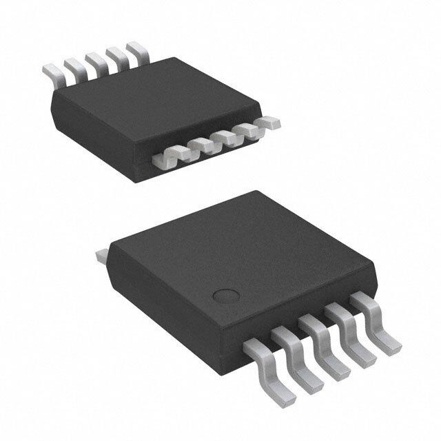
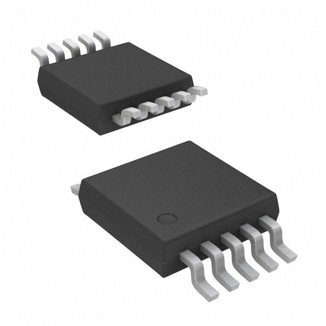
ICGOO电子元器件商城为您提供TPS62051DGS由Texas Instruments设计生产,在icgoo商城现货销售,并且可以通过原厂、代理商等渠道进行代购。 TPS62051DGS价格参考¥10.78-¥19.23。Texas InstrumentsTPS62051DGS封装/规格:PMIC - 稳压器 - DC DC 开关稳压器, 可调式 降压 开关稳压器 IC 正 0.7V 1 输出 800mA 10-TFSOP,10-MSOP(0.118",3.00mm 宽)。您可以下载TPS62051DGS参考资料、Datasheet数据手册功能说明书,资料中有TPS62051DGS 详细功能的应用电路图电压和使用方法及教程。
TPS62051DGS 是 Texas Instruments(德州仪器)生产的一款高效、低功耗的 DC-DC 降压型开关稳压器,广泛应用于对效率和空间有较高要求的便携式电子设备中。

其主要应用场景包括:

1. 便携式电子产品:如智能手机、平板电脑、PDA 等,TPS62051DGS 具有高效率和小封装特性,适合电池供电设备中为处理器、内存等关键部件提供稳定电压。

2. 无线通信设备:用于无线模块、射频收发器等设备中的电源管理,支持宽输入电压范围,适应不同电池配置。

3. 传感器系统:在工业自动化和物联网(IoT)设备中,作为传感器节点的电源调节器,提供稳定的工作电压,延长电池寿命。

4. 嵌入式控制系统:如工控主板、智能仪表等,用于将较高的电池或电源电压转换为芯片所需的 1.8V、2.5V 或 3.3V 等标准电压。

5. 汽车电子:适用于车载信息娱乐系统、驾驶辅助模块等场景,在较宽温度范围内保持稳定输出。

该器件采用小型 TSSOP 封装,具备轻载高效模式、快速瞬态响应和过温保护等功能,适用于需要高效能与可靠性的多种低功耗应用。
| 参数 | 数值 |
| 产品目录 | 集成电路 (IC)半导体 |
| 描述 | IC REG BUCK SYNC ADJ 0.8A 10MSOP稳压器—开关式稳压器 Adj 800-mA 10V Vin Step-Down Converter |
| 产品分类 | |
| 品牌 | Texas Instruments |
| 产品手册 | |
| 产品图片 |
|
| rohs | 符合RoHS无铅 / 符合限制有害物质指令(RoHS)规范要求 |
| 产品系列 | 电源管理 IC,稳压器—开关式稳压器,Texas Instruments TPS62051DGS- |
| 数据手册 | |
| 产品型号 | TPS62051DGS |
| PCN设计/规格 | |
| PWM类型 | 电压模式 |
| 产品目录页面 | |
| 产品种类 | 稳压器—开关式稳压器 |
| 供应商器件封装 | 10-VSSOP |
| 其它名称 | 296-14209-5 |
| 包装 | 管件 |
| 单位重量 | 23.700 mg |
| 同步整流器 | 是 |
| 商标 | Texas Instruments |
| 安装类型 | 表面贴装 |
| 安装风格 | SMD/SMT |
| 宽度 | 3 mm |
| 封装 | Tube |
| 封装/外壳 | 10-TFSOP,10-MSOP(0.118",3.00mm 宽) |
| 封装/箱体 | VSSOP-10 |
| 工作温度 | -40°C ~ 85°C |
| 工作温度范围 | - 40 C to + 85 C |
| 工厂包装数量 | 80 |
| 开关频率 | 850 kHz |
| 拓扑结构 | Buck |
| 最大工作温度 | + 85 C |
| 最大输入电压 | 10 V |
| 最小工作温度 | - 40 C |
| 最小输入电压 | 2.7 V |
| 标准包装 | 80 |
| 电压-输入 | 2.7 V ~ 10 V |
| 电压-输出 | 0.7 V ~ 6 V |
| 电流-输出 | 800mA |
| 类型 | 降压(降压) |
| 系列 | TPS62051 |
| 负载调节 | 0.0045 % / mA |
| 输入电压 | 2.7 V to 10 V |
| 输出数 | 1 |
| 输出电压 | 0.7 V to 6 V |
| 输出电流 | 800 mA |
| 输出端数量 | 1 Output |
| 输出类型 | 可调式 |
| 频率-开关 | 850kHz |


- 商务部:美国ITC正式对集成电路等产品启动337调查
- 曝三星4nm工艺存在良率问题 高通将骁龙8 Gen1或转产台积电
- 太阳诱电将投资9.5亿元在常州建新厂生产MLCC 预计2023年完工
- 英特尔发布欧洲新工厂建设计划 深化IDM 2.0 战略
- 台积电先进制程称霸业界 有大客户加持明年业绩稳了
- 达到5530亿美元!SIA预计今年全球半导体销售额将创下新高
- 英特尔拟将自动驾驶子公司Mobileye上市 估值或超500亿美元
- 三星加码芯片和SET,合并消费电子和移动部门,撤换高东真等 CEO
- 三星电子宣布重大人事变动 还合并消费电子和移动部门
- 海关总署:前11个月进口集成电路产品价值2.52万亿元 增长14.8%


PDF Datasheet 数据手册内容提取
Product Sample & Technical Tools & Support & Folder Buy Documents Software Community TPS62050,TPS62051,TPS62052,TPS62054,TPS62056 SLVS432F–SEPTEMBER2002–REVISEDJUNE2015 TPS6205x 800-mA Synchronous Step-Down Converter 1 Features 3 Description • High-EfficiencySynchronousStep-Down The TPS6205x devices are a family of high-efficiency 1 synchronous step-down DC-DC converters that are ConverterWithupto95%Efficiency ideally suited for systems powered from a 1- or 2-cell • 12-µAQuiescentCurrent(Typical) Li-Ion battery or from a 3- to 5-cell NiCd, NiMH, or • 2.7-Vto10-VOperatingInputVoltageRange alkalinebattery. • AdjustableOutputVoltageRange:0.7Vto6V The TPS6205x devices are synchronous pulse width • FixedOutputVoltageOptionsAvailableWith modulation (PWM) converters with integrated N- and 1.5V,1.8V,and3.3V P-channel power MOSFET switches. Synchronous rectification increases efficiency and reduces external • SynchronizabletoExternalClock:Upto1.2MHz component count. To achieve highest efficiency over • High-EfficiencyOveraWideLoadCurrentRange a wide load current range, the converter enters a inPower-SaveMode power-saving pulse frequency modulation (PFM) • 100%MaximumDutyCycleforLowestDropout mode at light load currents. Operating frequency is typically 850 kHz, allowing the use of small inductor • Low-NoiseOperationinForcedFixed- and capacitor values. The device can be FrequencyPWMOperationMode synchronized to an external clock signal in the range • InternalSoftstart of 600 kHz to 1.2 MHz. For low noise operation, the • OvertemperatureandOvercurrentProtected converter can be programmed into forced-fixed frequency in PWM mode. In shutdown mode, the • Availablein10-PinMicro-SmallOutline current consumption is reduced to less than 2 µA. PackageMSOP The TPS6205x devices are available in the 10-pin (DGS) micro-small outline package (MSOP) and 2 Applications operates over a free air temperature range of –40°C • CellularPhones to85°C. • Organizers,PDAs,andHandheldPCs DeviceInformation(1) • Low-PowerDSPSupplies PARTNUMBER PACKAGE BODYSIZE(NOM) • DigitalCamerasandHardDisks TPS62050 TPS62051 TPS62052 VSSOP(10) 3.00mm×3.00mm TPS62054 TPS62056 (1) For all available packages, see the orderable addendum at theendofthedatasheet. 4 Typical Application Schematic EfficiencyvsOutputCurrent VI= 3.3 V to 10 V 1 VIN SW 9 L1 = 10µH VO= 1.5 V / 800 mA 100 90 8 5 80 EN FB 70 TPS62052 Ci= 10µF 6 LBI PG 4 y–% 60 Co= 22µF nc 50 7 SYNC LBO 2 Efficie 40 GND PGND 30 3 10 20 VI=7.2V, VO=5V, 10 SYNC=L 0 0.01 0.1 1 10 100 1k IO–Output Current–mA 1 An IMPORTANT NOTICE at the end of this data sheet addresses availability, warranty, changes, use in safety-critical applications, intellectualpropertymattersandotherimportantdisclaimers.PRODUCTIONDATA.
TPS62050,TPS62051,TPS62052,TPS62054,TPS62056 SLVS432F–SEPTEMBER2002–REVISEDJUNE2015 www.ti.com Table of Contents 1 Features.................................................................. 1 9.4 DeviceFunctionalModes........................................10 2 Applications........................................................... 1 10 ApplicationandImplementation........................ 12 3 Description............................................................. 1 10.1 ApplicationInformation..........................................12 4 TypicalApplicationSchematic............................. 1 10.2 TypicalApplications..............................................12 10.3 SystemExamples.................................................19 5 RevisionHistory..................................................... 2 11 PowerSupplyRecommendations..................... 20 6 DeviceComparisonTable..................................... 3 12 Layout................................................................... 20 7 PinConfigurationandFunctions......................... 3 12.1 LayoutGuidelines.................................................20 8 Specifications......................................................... 4 12.2 LayoutExample....................................................20 8.1 AbsoluteMaximumRatings......................................4 13 DeviceandDocumentationSupport................. 22 8.2 ESDRatings..............................................................4 13.1 DeviceSupport......................................................22 8.3 RecommendedOperatingConditions.......................4 13.2 RelatedLinks........................................................22 8.4 ThermalInformation..................................................4 13.3 CommunityResource............................................22 8.5 ElectricalCharacteristics...........................................5 13.4 Trademarks...........................................................22 8.6 TypicalCharacteristics..............................................6 13.5 ElectrostaticDischargeCaution............................22 9 DetailedDescription.............................................. 7 13.6 Glossary................................................................22 9.1 Overview...................................................................7 14 Mechanical,Packaging,andOrderable 9.2 FunctionalBlockDiagram.........................................7 Information........................................................... 22 9.3 FeatureDescription...................................................8 5 Revision History NOTE:Pagenumbersforpreviousrevisionsmaydifferfrompagenumbersinthecurrentversion. ChangesfromRevisionE(June2011)toRevisionF Page • AddedPinConfigurationandFunctionssection,ESDRatingstable,FeatureDescriptionsection,DeviceFunctional Modes,ApplicationandImplementationsection,PowerSupplyRecommendationssection,Layoutsection,Device andDocumentationSupportsection,andMechanical,Packaging,andOrderableInformationsection .............................. 1 ChangesfromRevisionD(October2003)toRevisionE Page • ChangedtoRevisionE,June2011........................................................................................................................................ 1 • Changedformatting................................................................................................................................................................ 1 • Changed"goesactivehigh"to"floats"inTerminalFunctionstable,rowPG,description..................................................... 3 • Changed"becomesactive"to"floats"inlastparagraphofPowerGoodComparatorsection............................................ 10 2 SubmitDocumentationFeedback Copyright©2002–2015,TexasInstrumentsIncorporated ProductFolderLinks:TPS62050 TPS62051 TPS62052 TPS62054 TPS62056
TPS62050,TPS62051,TPS62052,TPS62054,TPS62056 www.ti.com SLVS432F–SEPTEMBER2002–REVISEDJUNE2015 6 Device Comparison Table PACKAGEDDEVICES OUTPUTVOLTAGE LBI/LBOFUNCTIONALITY PLASTICMSOP(1)(DGS) TPS62050DGS Adjustable0.7Vto6V Standard TPS62051DGS Adjustable0.7Vto6V Enhanced TPS62052DGS 1.5V Standard TPS62054DGS 1.8V Standard TPS62056DGS 3.3V Standard (1) TheDGSpackagesareavailabletapedandreeled.AddanRsuffixtothedevicetype(thatis,TPS62050DGSR)toorderquantitiesof 2500devicesperreel. 7 Pin Configuration and Functions DGSPackage 10-PinVSSOP TopView VIN 1 10 PGND LBO 2 9 SW GND 3 8 EN PG 4 7 SYNC FB 5 6 LBI PinFunctions PIN I/O DESCRIPTION NAME NO. EN 8 I Enable.Alogichighenablestheconverter,logiclowforcesthedeviceintoshutdownmode,reducingthesupply currenttolessthan2µA. FB 5 I Feedbackpinforthefixedoutputvoltageoption.Fortheadjustableversion,anexternalresistivedivideris connectedtothispin.Theinternalvoltagedividerisdisabledfortheadjustableversion. GND 3 I Ground LBI 6 I Lowbatteryinput. LBO 2 O Open-drainlowbatteryoutput.Logiclowsignalindicatesalowbatteryvoltage. PG 4 O Powergoodcomparatoroutput.Thisisanopen-drainoutput.ApullupresistormustbeconnectedbetweenPG andVOUT.Theoutputfloatswhentheoutputvoltageisgreaterthan95%ofthenominalvalue. PGND 10 I Powerground.Connectallpowergroundstothispin. SW 9 O Connecttheinductortothispin.Thispinistheswitchpinandconnectedtothedrainoftheinternalpower MOSFETS. SYNC 7 I Inputforsynchronizationtotheexternalclocksignal.Thisinputcanbeconnectedtoanexternalclockorpulledto GNDorV.Whenanexternalclocksignalisapplied,thedevicesynchronizestothisexternalclockandthedevice I operatesinfixedPWMmode.WhenthepinispulledtoeitherGNDorV,theinternaloscillatorisusedandthe I logicleveldeterminesifthedeviceoperatesinfixedPWMorPWM/PFMmode. SYNC=HIGH:Low-noisemodeenabled,fixed-frequencyPWMoperationisforced. SYNC=LOW(GND):Powersavemodeenabled,PFM/PWMmodeenabled. VIN 1 I Supplyvoltageinput. Copyright©2002–2015,TexasInstrumentsIncorporated SubmitDocumentationFeedback 3 ProductFolderLinks:TPS62050 TPS62051 TPS62052 TPS62054 TPS62056
TPS62050,TPS62051,TPS62052,TPS62054,TPS62056 SLVS432F–SEPTEMBER2002–REVISEDJUNE2015 www.ti.com 8 Specifications 8.1 Absolute Maximum Ratings Overoperatingfree-airtemperaturerangeunlessotherwisenoted(1) MIN MAX UNIT V Supplyvoltage –0.3 11 V I VoltageatEN,SYNC –0.3 V V I VoltageatLBI,FB,LBO,PG –0.3 7 V VoltageatSW –0.3 11(2) V I Outputcurrent 850 mA O T Maximumjunctiontemperature 150 °C J T Operatingfree-airtemperature –40 85 °C A Leadtemperature1.6mm(1/16inch)fromcasefor10seconds 300 °C T Storagetemperature –65 150 °C stg (1) StressesbeyondthoselistedunderAbsoluteMaximumRatingsmaycausepermanentdamagetothedevice.Thesearestressratings only,whichdonotimplyfunctionaloperationofthedeviceattheseoranyotherconditionsbeyondthoseindicatedunderRecommended OperatingConditions.Exposuretoabsolute-maximum-ratedconditionsforextendedperiodsmayaffectdevicereliability. (2) ThevoltageattheSWpinissampledinPFMmode15µsafterthePMOShasswitchedoff.DuringthistimethevoltageatSWislimited to7Vmaximum.Therefore,theoutputvoltageoftheconverterislimitedto7Vmaximum. 8.2 ESD Ratings VALUE UNIT Humanbodymodel(HBM),perANSI/ESDA/JEDECJS-001,allpins(1) ±2000 V(ESD) Electrostaticdischarge Chargeddevicemodel(CDM),perJEDECspecificationJESD22-C101, V allpins(2) ±500 (1) JEDECdocumentJEP155statesthat500-VHBMallowssafemanufacturingwithastandardESDcontrolprocess. (2) JEDECdocumentJEP157statesthat250-VCDMallowssafemanufacturingwithastandardESDcontrolprocess. 8.3 Recommended Operating Conditions MIN NOM MAX UNIT SupplyvoltageatV 2.7 10 V I VoltageatPG,LBO 6 V Maximumoutputcurrent 800(1) mA Operatingjunctiontemperature –40 125 °C (1) Assumingnothermallimitation 8.4 Thermal Information TPS6205x THERMALMETRIC(1) DGS(VSSOP) UNIT 10PINS R Junction-to-ambientthermalresistance 154 °C/W θJA R Junction-to-case(top)thermalresistance 50.6 °C/W θJC(top) R Junction-to-boardthermalresistance 73.6 °C/W θJB ψ Junction-to-topcharacterizationparameter 5.1 °C/W JT ψ Junction-to-boardcharacterizationparameter 72.4 °C/W JB (1) Formoreinformationabouttraditionalandnewthermalmetrics,seetheSemiconductorandICPackageThermalMetricsapplication report,SPRA953. 4 SubmitDocumentationFeedback Copyright©2002–2015,TexasInstrumentsIncorporated ProductFolderLinks:TPS62050 TPS62051 TPS62052 TPS62054 TPS62056
TPS62050,TPS62051,TPS62052,TPS62054,TPS62056 www.ti.com SLVS432F–SEPTEMBER2002–REVISEDJUNE2015 8.5 Electrical Characteristics V =7.2V,V =3.3V,I =300mA,EN=V,T =–40°Cto85°C(unlessotherwisenoted) I O O I A PARAMETER TESTCONDITIONS MIN TYP MAX UNIT SUPPLYCURRENT VI Inputvoltage 2.7 10 V I(Q) Operatingquiescentcurrent IO=0mA,SYNC=GND,VI=7.2V 12 20 µA EN=GND 1.5 5 I(SD) Shutdowncurrent µA EN=GND,TA=25°C 1.5 3 QuiescentcurrentwithenhancedLBIcomparator IQ(LBI) version. EN=VI,LBI=GND,TPS62051only 5 µA ENABLE VIH ENhighlevelinputvoltage 1.3 V VIL ENlowlevelinputvoltage 0.3 V ENtrippointhysteresis 100 mV Ilkg ENinputleakagecurrent EN=GNDorVIN,VI=7.2V 0.01 0.2 µA I(EN) ENinputcurrent 0.6V≤V(EN)≤4V 2 µA V(UVLO) Undervoltagelockoutthreshold 1.6 V POWERSWITCH VI≥5.4V;IO=300mA 400 650 RDS(ON) P-channelMOSFETON-resistance mΩ VI=2.7V;IO=300mA 600 850 P-channelMOSFETleakagecurrent VDS=10V 1 µA P-channelMOSFETcurrentlimit VI=7.2V,VO=3.3V 1000 1200 1400 mA VI≥5.4V;IO=300mA 300 450 RDS(ON) N-channelMOSFETON-resistance mΩ VI=2.7V;IO=300mA 450 550 N-channelMOSFETleakagecurrent VDS=6V 1 µA POWERGOODOUTPUT,LBI,LBO V(PG) Powergoodtripvoltage Vml–2% V VOrampingpositive 50 Powergooddelaytime µs VOrampingnegative 200 VOL PG,LBOoutputlowvoltage V(FB)=0.8×VOnominal,I(sink)=1mA 0.3 V PG,LBOoutputleakagecurrent V(FB)=VOnominal,V(LBI)=VI 0.01 0.25 µA Minimumsupplyvoltageforvalidpowergood,LBO 2.3 V signal V(LBI) Low-batteryinputtripvoltage Inputvoltagefalling 1.21 V Low-batteryinputtrippointaccuracy 1.5% V(LBI,HYS) Low-batteryinputhysteresis 15 mV Ilkg(LBI) LBIleakagecurrent 0.01 0.1 µA OSCILLATOR fS Oscillatorfrequency 600 850 1000 kHz f(SYNC) Synchronizationrange 600 1200 kHz VIH SYNChigh-levelinputvoltage 1.5 V VIL SYNClow-levelinputvoltage 0.3 V Ilkg SYNCinputleakagecurrent SYNC=GNDorVIN 0.01 0.1 µA SYNCtrippointhysteresis 100 mV Dutycycleofexternalclocksignal 20% 90% OUTPUT VO Adjustableoutputvoltage TPS62050,TPS62051 0.7 6 V V(FB) Feedbackvoltage TPS62050,TPS62051 0.5 V FBleakagecurrent TPS62050,TPS62051 0.02 0.1 µA Feedbackvoltagetolerance TPS62050,TPS62051 VI=2.7Vto10V,0mA<IO<600mA –3% 3% Copyright©2002–2015,TexasInstrumentsIncorporated SubmitDocumentationFeedback 5 ProductFolderLinks:TPS62050 TPS62051 TPS62052 TPS62054 TPS62056
TPS62050,TPS62051,TPS62052,TPS62054,TPS62056 SLVS432F–SEPTEMBER2002–REVISEDJUNE2015 www.ti.com Electrical Characteristics (continued) V =7.2V,V =3.3V,I =300mA,EN=V,T =–40°Cto85°C(unlessotherwisenoted) I O O I A PARAMETER TESTCONDITIONS MIN TYP MAX UNIT TPS62052 VI=2.7Vto10V,0mA<IO<600mA –3% 3% Fixedoutputvoltage tolerance(1) TPS62054 VI=2.7Vto10V,0mA<IO<600mA –3% 3% TPS62056 VI=3.75Vto10V,0mA<IO<600mA –3% 3% Resistanceofinternalvoltagedividerforfixed-voltage 700 1000 1300 kΩ versions Lineregulation VO=3.3V,VI=5Vto10V,IO=600mA 5.2 mV/V Loadregulation VI=7.2V;IO=10mAto600mA 0.0045 %/mA VI=5V;VO=3.3V;IO=300mA 93% η Efficiency VI=3.6V;VO=2.5V;IO=200mA 93% Dutycyclerangeformainswitches 100% Minimumtontimeformainswitch 100 ns Shutdowntemperature 145 °C Start-uptime IO=200mA,VI=5V,Vo=3.3V, 1 ms Co=22µF,L=10µH (1) TheworstcaseR ofthePMOSin100%modeforaninputvoltageof3.3Vis0.75Ω.Thisvaluecanbeusedtodeterminethe DS(ON) minimuminputvoltageiftheoutputcurrentislessthan600mAwiththeTPS62056. 8.6 Typical Characteristics 900 2.7V 890 3.6V 880 Hz k 870 − cy 860 5V n e qu 850 e g Fr 840 7.2V n hi 830 c wit 820 S 810 800 −40 −20 0 20 40 60 80 100 TA−Free-Air Temperature−°C Figure1.SwitchingFrequencyvsFree-AirTemperature 6 SubmitDocumentationFeedback Copyright©2002–2015,TexasInstrumentsIncorporated ProductFolderLinks:TPS62050 TPS62051 TPS62052 TPS62054 TPS62056
TPS62050,TPS62051,TPS62052,TPS62054,TPS62056 www.ti.com SLVS432F–SEPTEMBER2002–REVISEDJUNE2015 9 Detailed Description 9.1 Overview The TPS6205x family of devices are synchronous step-down converters that operate with a 850-kHz fixed- frequencypulsewidthmodulation(PWM)atmoderatetoheavyloadcurrentsandentersthepowersavemodeat lightloadcurrent. During PWM operation, the converter uses a unique fast response voltage mode control scheme with input voltage feed forward to achieve good line and load regulation with the use of small ceramic input and output capacitors. At the beginning of each clock cycle initiated by the clock signal (S), the P-channel MOSFET switch is turned on and the inductor current ramps up until the voltage comparator trips and the control logic turns the switch off. Also the switch is turned off by the current limit comparator if the current limit of the P-channel switch is exceeded. After the dead time preventing current shoot through, the N-channel MOSFET rectifier is turned on and the inductor current ramps down. The next cycle is initiated by the clock signal again, turning off the N- channelrectifierandturningontheP-channelswitch. The error amplifier as well as the input voltage determines the rise time of the saw tooth generator; therefore, any change in input voltage or output voltage directly controls the duty cycle of the converter giving a very good lineandloadtransientregulation. 9.2 Functional Block Diagram VI Current Limit Comparator + Undervoltage Lockout – REF Bias Supply SYNC Soft Start + I(AVG) Comparator – REF V I 850 kHz V(COMP) Oscillator P-Channel Comparator Power MOSFET S + Saw Tooth R Control Driver SW – Shoot-Through Generator Logic Comparator High Logic N-Channel Comparator Low Power MOSFET Comparator High2 Load Comparator + SKIP Comparator – PG Error Amp Comparator High + LBO Compensation R1 – – Comparator Low R2 + + Comparator Low2 VREF = 0.5 V _ See Note 1.21 V EN FB LBI PGND GND NOTE:Fortheadjustableversions(TPS62050,TPS62051devices),theinternalfeedbackdriverisdisabledandthe FBpinisdirectlyconnectedtotheGMamplifier. Copyright©2002–2015,TexasInstrumentsIncorporated SubmitDocumentationFeedback 7 ProductFolderLinks:TPS62050 TPS62051 TPS62052 TPS62054 TPS62056
TPS62050,TPS62051,TPS62052,TPS62054,TPS62056 SLVS432F–SEPTEMBER2002–REVISEDJUNE2015 www.ti.com 9.3 Feature Description 9.3.1 EnableandOvertemperatureProtection A logic low on EN forces the TPS6205x devices into shutdown. In shutdown, the power switch, drivers, voltage reference, oscillator, and all other functions are turned off. The supply current is reduced to less than 2 µA in the shutdown mode. When the device is in thermal shutdown, the bandgap is forced to stay on even if the device is set into shutdown by pulling EN to GND. As soon as the temperature drops below the threshold, the device automaticallystartsagain. If an output voltage is present when the device is disabled, which could be an external voltage source or super cap,thereverseleakagecurrentisspecifiedunderElectricalCharacteristics.Pullingtheenablepinhighstartsup the TPS6205x devices with the soft-start as described in Soft-Start. If the EN pin is connected to any voltage otherthanV orGND,anincreasedleakagecurrentoftypically10 µAandupto20 µAcanoccur. I VIN VIN 0 m A for VEN < 0.6 V Typically 0.3 m A to 5 m Afor VEN < 4 V 5 V Vt = 0.7 V EN Enable to Internal Circuitry Figure2. InternalCircuitoftheENABLEPin The EN pin can be used in a pushbutton configuration as shown in Figure 3. The external resistor to GND must be capable of sinking 0.3 µA with a minimum voltage drop of 1.3 V to keep the system enabled when both switches are open. When the ON-button is pressed, the device is enabled and the current through the external resistor keeps the voltage level high to ensure that the device stays on when the ON-button is released. When the OFF-button is pressed, the device is switched off and the current through the external resistor is zero. The devicethereforestaysoffevenwhentheOFF-buttonisreleased. VIN ON TPS6205x EN 0.3 m A, min OFF R >1.3 V/0.3 m A Figure3. PushbuttonConfigurationfortheEN-Pin 9.3.2 Low-BatteryDetector(StandardVersion) The low-battery output (LBO) is an open-drain type which goes low when the voltage at the low battery input (LBI)fallsbelowthetrippointof1.21V ±1.5%.Thevoltageatwhichthelow-batterywarningisissuedisadjusted with a resistive divider as shown in Figure 5. TI recommends the sum of the resistors R1 and R2 to be in the 100-kΩ to 1-MΩ range for high-efficiency at low output current. An external pullup resistor at LBO can either be connected to OUT, or any other voltage rail in the voltage range of 0 V to 6 V. During start-up, the LBO output signal is invalid for the first 500 µs. LBO is high impedance when the device is disabled. If the low-battery comparator function is not used, connect LBI to ground. The low-battery detector is disabled when the device is disabled.LeavetheLBOpinunconnected,orconnecttoGNDwhennotused. 8 SubmitDocumentationFeedback Copyright©2002–2015,TexasInstrumentsIncorporated ProductFolderLinks:TPS62050 TPS62051 TPS62052 TPS62054 TPS62056
TPS62050,TPS62051,TPS62052,TPS62054,TPS62056 www.ti.com SLVS432F–SEPTEMBER2002–REVISEDJUNE2015 Feature Description (continued) 9.3.3 ENABLE/Low-BatteryDetector(EnhancedVersion)TPS62051Only The TPS62051 device offers an enhanced LBI functionality to provide a precise, user-programmable undervoltageshutdown.Noadditionalsupplyvoltagesupervisor(SVS)isneededtoprovidethisfunction. When the enable (EN) pin is pulled high, only the internal bandgap voltage reference is switched on to provide a reference source for the LBI comparator. As long as the voltage at LBI is less than the LBI trip point, all other internal circuits are shut down, reducing the supply current to 5 µA. As soon as input voltage at LBI rises above theLBItrippointof1.21V,thedeviceiscompletelyenabledandstartsswitching. VIN ENABLE Bandgap Enable to Internal Circuitry LBI LBI LBO Comparator Figure4. BlockDiagramofENABLE/LBIFunctionalityforTPS62051 ThelogicleveloftheLBOpinisnotdefinedforthefirst500 µsafterENispulledhigh. When the enhanced LBI is used to supervise the battery voltage and shut down the TPS62051 at low input voltages, the battery voltage rises again when the current drops to zero. The implemented hysteresis on the LBI pin may not be sufficient for all types of batteries. Figure 5 shows how an additional external hysteresis can be implemented. L1 = 10 m H VO = 2.5 V / 600 mA 1 9 VIN SW 8 5 EN FB R3 R4 R1 R5 TPS62051 C(ff) = 6.8 pF 1 Cell Li-lon Ci = 10 m F 6 LBI PG 4 R2 7 2 R6 SYNC LBO Co = 22 m F GND PGND 3 10 R7 Figure5. EnhancedLBIWithIncreasedHysteresis AMATHCAD®filetocalculateR7canbedownloadedfromtheproductfolder ontheTIweb. 9.3.4 UndervoltageLockout The undervoltage lockout (UVLO) circuit prevents the device from misoperation at low input voltages. The circuit preventstheconverterfromturningontheswitchorrectifierMOSFETunderundefinedconditions. Copyright©2002–2015,TexasInstrumentsIncorporated SubmitDocumentationFeedback 9 ProductFolderLinks:TPS62050 TPS62051 TPS62052 TPS62054 TPS62056
TPS62050,TPS62051,TPS62052,TPS62054,TPS62056 SLVS432F–SEPTEMBER2002–REVISEDJUNE2015 www.ti.com Feature Description (continued) 9.3.5 PowerGoodComparator Thepowergood(PG)comparatorhasanopen-drainoutputcapableofsinkingtypically1mA.ThePGfunctionis only active when the device is enabled (EN = high). When the device is disabled (EN = low), the PG pin is pulled toGND. The PG output is only valid after a 250-µs delay after the device is enabled and the supply voltage is greater than2.7V.Powergoodislowduringthefirst250µsaftershutdownandinshutdown. The PG pin floats high when the output voltage exceeds typically 98.5% of its nominal value. Leave the PG pin unconnected,orconnectittoGNDwhennotused. 9.3.6 Synchronization If no clock signal is applied, the converter operates with a typical switching frequency of 850 kHz. It is possible to synchronize the converter to an external clock within a frequency range from 600 kHz to 1200 kHz. The device automaticallydetectstherisingedgeofthefirstclockandsynchronizestotheexternalclock.Iftheclocksignalis stopped, the converter automatically switches back to the internal clock and continues operation. The switchover is initiated if no rising edge on the SYNC pin is detected for a duration of four clock cycles. Therefore, the maximum delay time can be 8.3 µs if the internal clock has its minimum frequency of 600 kHz. During this time, there is no clock signal available. The device stops switching until the internal circuitry is switched to the internal clocksource. When the device is switched between internal synchronization and external synchronization during operation, the output voltage may show transient overshoot or undershoot during switchover. The voltage transients are minimized by using 850 kHz as an initial external frequency, and changing the frequency slowly (>1 ms) to the value desired. The voltage drop at the output when the device is switched from external synchronization to internalsynchronizationcanbereducedbyincreasingtheoutputcapacitorvalue. If the device is synchronized to an external clock, the power-save mode is disabled and the device stays in forcedPWMmode. Connecting the SYNC pin to the GND pin enables the power-save mode. The converter operates in the PWM modeatmoderatetoheavyloadsandinthePFMmodeduringlightloadsmaintaininghigh-efficiencyoverawide loadcurrentrange. 9.4 Device Functional Modes 9.4.1 Soft-Start The TPS6205x device have an internal soft-start circuit that limits the inrush current during start-up. This prevents possible voltage drops of the input voltage if a battery or a high impedance power source is connected totheinputoftheTPS6205xdevices. The soft-start is implemented as a digital circuit increasing the switch current in steps of 200 mA, 400 mA, 800 mA and then the typical switch current limit of 1.2 A. Therefore the start-up time mainly depends on the output capacitor and load current. Typical start-up time with a 22-µF output capacitor and a 200-mA load current is 1 ms. 9.4.2 ConstantFrequencyModeOperation(SYNC=HIGH) In the constant frequency mode, the output voltage is regulated by varying the duty cycle of the PWM signal in the range of 100% to 10%. Connecting the SYNC pin to a voltage greater than 1.5 V forces the converter to operate permanently in the PWM mode even at light or no load currents. The advantage is the converter operateswithafixedswitchingfrequencythatallowssimplefilteringoftheswitchingfrequencyfornoisesensitive applications. In this mode, the efficiency is lower compared to the power-save mode during light loads (see Figure 7). The N-MOSFET of the devices stays on even when the current into the output drops to zero. This prevents the device from going into discontinuous mode. The device transfers unused energy back to the input. Therefore, there is no ringing at the output that usually occurs in the discontinuous mode. The duty cycle range inconstantfrequencymodeis100%to10%. 10 SubmitDocumentationFeedback Copyright©2002–2015,TexasInstrumentsIncorporated ProductFolderLinks:TPS62050 TPS62051 TPS62052 TPS62054 TPS62056
TPS62050,TPS62051,TPS62052,TPS62054,TPS62056 www.ti.com SLVS432F–SEPTEMBER2002–REVISEDJUNE2015 Device Functional Modes (continued) ItispossibletoswitchfromforcedPWMmodetothepower-savemodeduringoperationbypullingtheSYNCpin low.TheflexibleconfigurationoftheSYNCpinduringoperationofthedeviceallowsefficientpowermanagement byadjustingtheoperationoftheTPS6205xdevicestothespecificsystemrequirements. 9.4.3 Power-SaveModeOperation(SYNC=LOW) As the load current decreases, the converter enters the power-save mode operation. During power-save mode the converter operates with reduced switching frequency in PFM and with a minimum quiescent current to maintain high-efficiency. Whenever the average output current goes below the skip threshold, the converter enters the power-save mode. The average current depends on the input voltage. The current is 100 mA at low input voltages and up to 200mA with maximum input voltage. The average output current must be less than the thresholdforatleast32clockcycles(t )toenterthepower-savemode.Duringthepowersavemode,theoutput cy voltage is monitored with a comparator. When the output voltage falls below the comparator low threshold set to 0.8% above V nominal, the P-channel switch turns on. The P-channel switch turns off as the peak switch O current of typically 200 mA is reached. The N-channel rectifier turns on and the inductor current ramps down. As the inductor current approaches zero, the N-channel rectifier is turned off and the switch is turned on starting the next pulse. When the output voltage can not be reached with a single pulse, the device continues to switch with its normal operating frequency, until the comparator detects the output voltage to be 1.6% above the nominal output voltage. The converter wakes up again when the output voltage falls below the comparator low threshold. This control method reduces the quiescent current to typically to 12 µA and the switching frequency to a minimum achieving the highest converter efficiency. Having these skip current thresholds 0.8% and 1.6% above the nominal output voltage gives a lower absolute voltage drop during a load transient as anticipated with a standardconverteroperatinginthismode. 9.4.4 100%DutyCycleLowDropoutOperation The TPS6205x devices offer the lowest possible input to output voltage difference while still maintaining operation with the use of the 100% duty cycle mode. In this mode, the P-channel switch is constantly turned on. This is particularly useful in battery-powered applications to achieve longest operation time by taking full advantage of the whole battery voltage range. The minimum input voltage to maintain regulation depends on the loadcurrentandoutputvoltageandcanbecalculatedusingEquation1. ( ) V(min)=V (max)+I (max)´ R (max)+R I O O DS(ON) L I (max)=Maximumoutputcurrentplusinductorripplecurrent O R (max)=MaximumP-Channelswitchresistance DS(ON) R =DCresistanceoftheinductor L V (max)=Nominaloutputvoltageplusmaximumoutputvoltagetolerance O (1) 9.4.5 NoLoadOperation If the converter operates in the forced PWM mode and there is no load connected to the output, the converter regulatestheoutputvoltagebyallowingtheinductorcurrenttoreverseforashortperiodoftime. Copyright©2002–2015,TexasInstrumentsIncorporated SubmitDocumentationFeedback 11 ProductFolderLinks:TPS62050 TPS62051 TPS62052 TPS62054 TPS62056
TPS62050,TPS62051,TPS62052,TPS62054,TPS62056 SLVS432F–SEPTEMBER2002–REVISEDJUNE2015 www.ti.com 10 Application and Implementation NOTE Information in the following applications sections is not part of the TI component specification, and TI does not warrant its accuracy or completeness. TI’s customers are responsible for determining suitability of components for their purposes. Customers should validateandtesttheirdesignimplementationtoconfirmsystemfunctionality. 10.1 Application Information The TPS6205x family of devices are high-efficiency synchronous step-down DC-DC converters ideally suited for systemspoweredfroma1-cellor2-cellLi-Ionbatteryorfroma3-cellto5-cellNiCd,NiMH,oralkalinebattery. 10.2 Typical Applications 10.2.1 StandardCircuitforAdjustableVersion WE PD 744 777 10 VI 1 9 L1 = 10mH VO= 5 V VIN SW R5 8 5 R3 R4 130 kW EN FB 1 M 1 M C(ff)= 6.8 pF TPS62050 R1 = Ci= 10mF 6 4 820 kW C3216X5R1A1T0D6MK R6 LBI PG Co= 22mF 100 kW 7 2 TaiyoYuden SYNC LBO R2 = 91 kW JMK316BJ226ML GND PGND 3 10 Quiescent Current Measurements and Efficiency WereTaken With: R5 = Open, R4 = Open, LBI Connected to GND. Figure6. StandardCircuitforAdjustableVersion 10.2.1.1 DesignRequirements The design guidelines provide a component selection to operate the adjustable device within the Recommended OperatingConditions. Table1.BillofMaterialsforAdjustableVersion REFERENCE PARTNUMBER VALUE MANUFACTURER Ci C3216X5R1A106M 10µF TDK Co JMK316BJ226ML 22µF TaiyoYuden L1 WEPD74477710 10µH Wurth IC1 TPS62050 - TexasInstruments genericmetalfilmresistor; 820kΩ(dependingondesired R1 — tolerance1% outputvoltage) genericmetalfilmresistor; 91kΩ(dependingondesired R2 — tolerance1% outputvoltage) genericmetalfilmresistor; R3,R4 1MΩ — tolerance1% genericmetalfilmresistor; R5 130kΩ — tolerance1% 12 SubmitDocumentationFeedback Copyright©2002–2015,TexasInstrumentsIncorporated ProductFolderLinks:TPS62050 TPS62051 TPS62052 TPS62054 TPS62056
TPS62050,TPS62051,TPS62052,TPS62054,TPS62056 www.ti.com SLVS432F–SEPTEMBER2002–REVISEDJUNE2015 Typical Applications (continued) Table1.BillofMaterialsforAdjustableVersion(continued) REFERENCE PARTNUMBER VALUE MANUFACTURER genericmetalfilmresistor; R6 100kΩ — tolerance1% C(ff) genericceramiccapacitor;COG 6.8pF — 10.2.1.2 DetailedDesignProcedure All graphs have been generated using the circuit as shown unless otherwise noted. For output voltages other than 5 V, the fixed-voltage versions were used. The resistors R1, R2, and the feed forward capacitor (C ) are ff removedandthefeedbackpinisdirectlyconnectedtotheoutput. (cid:4)V (cid:5) VO(cid:3)VFB(cid:1)R1R(cid:2)2R2 R1(cid:3)R2(cid:1) VO –R2 VFB(cid:3)0.5V FB (2) Table2.ValuesforResistorCombinationsandFeedbackCapacitors NOMINALOUTPUTVOLTAGE EQUATION POSSIBLERESISTORCOMBINATION TYPICALFEEDBACKCAPACITOR 0.7V R1=0.4×R2 R1=270k,R2=680k C =22pF (ff) 1.2V R1=1.4×R2 R1=510k,R2=360k(1.21V) C =6.8pF (ff) 1.5V R1=2×R2 R1=300k,R2=150k(1.5V) C =6.8pF (ff) 1.8V R1=2.6×R2 R1=390k,R2=150k(1.80V) C =6.8pF (ff) 2.5V R1=4×R2 R1=680k,R2=169k(2.51V) C =6.8pF (ff) 3.3V R1=5.6×R2 R1=560k,R2=100k(3.3V) C =6.8pF (ff) 5V R1=9×R2 R1=820k,R2=91k(5V) C =6.8pF (ff) 10.2.1.2.1 InductorSelection A 10-µH minimum inductor must be used with the TPS6205x family of devices. Values larger than 22 µH or smaller than 10 µH may cause stability problems due to the internal compensation of the regulator. After choosing the inductor value of typically 10 µH, two additional inductor parameters must be considered: the current rating of the inductor and the DC resistance. The DC resistance of the inductance directly influences the efficiency of the converter. Therefore, an inductor with lowest DC resistance must be selected for highest efficiency. To avoid saturation of the inductor, the inductor must be rated at least for the maximum output current plushalftheinductorripplecurrentwhichiscalculatedusingEquation3. V 1(cid:3) O V (cid:1)I (cid:4)V (cid:1) I I (max)(cid:4)I (max)(cid:2)(cid:1)IL L O L(cid:1)f L O 2 f = Switching frequency (850 kHz typical) L = Inductor value D IL = Peak-to-peak inductor ripple current I (max) = Maximum inductor current L (3) The highest inductor current occurs at maximum VIN . A more conservative approach is to select the inductor current rating just for the maximum switch current of the TPS6205x device, which is 1.4 A maximum. See Table3forinductorsthathavebeentestedforoperationwiththeTPS6205xdevices. Table3.Inductors MANUFACTURER TYPE INDUCTANCE DCRESISTANCE SATURATIONCURRENT SLF7032T- 10µH±20% 53mΩ±20% 1.4A 100M1R4SLF7032T- 22µH±20% 110mΩ±20% 0.96A TDK 220M96SLF7045T- 10µH±20% 36mΩ±20% 1.3A 100M1R3SLF7045T- 100MR90 22µH±20% 61mΩ±20% 0.9A Copyright©2002–2015,TexasInstrumentsIncorporated SubmitDocumentationFeedback 13 ProductFolderLinks:TPS62050 TPS62051 TPS62052 TPS62054 TPS62056
TPS62050,TPS62051,TPS62052,TPS62054,TPS62056 SLVS432F–SEPTEMBER2002–REVISEDJUNE2015 www.ti.com Table3.Inductors(continued) MANUFACTURER TYPE INDUCTANCE DCRESISTANCE SATURATIONCURRENT CDR74B 10µH 70mΩ 1.65A CDR74B 22µH 130mΩ 1.12A CDH74 10µH 49mΩ 1.8A CDH74 22µH 110mΩ 1.23A Sumida CDR63B 10µH 140mΩ 1A CDRH4D28 10µH 128mΩ 1A CDRH5D28 10µH 48mΩ 1.3A CDRH5D18 10µH 92mΩ 1.2A DT3316P-153 15µH 60mΩ 1.8A Coilcraft DT3316P-223 22µH 84mΩ 1.5A WE-PD74477810 10µH 72mΩ 1.68A WE-PD74477710 10µH 49mΩ 1.84A Wuerth WE-PD744778122 22µH 190mΩ 1.07A WE-PD744777122 22µH 110mΩ 1.23A 10.2.1.2.2 OutputCapacitorSelection The output capacitor must have a minimum value of 22 µF. For best performance, a low ESR ceramic output capacitorisneeded. Forcompleteness,useEquation4tocalculatetheRMSripplecurrent. V O 1– V I 1 IRMS(Co)(cid:2)VO (cid:1) L(cid:1)f (cid:1)2(cid:1)(cid:3)3 (4) The overall output ripple voltage is the sum of the voltage spike caused by the output capacitor ESR plus the voltageripplecausedbychargeanddischargingtheoutputcapacitor,asshowninEquation5. V O 1(cid:3) V (cid:1)VO(cid:4)VO (cid:1) L(cid:1)fI (cid:1)(cid:5)8(cid:1)C1o(cid:1)f(cid:2)RESR(cid:6) (5) ThehighestoutputvoltagerippleoccursatthehighestinputvoltageV. I 10.2.1.2.3 InputCapacitorSelection Because the buck converter has a pulsating input current, a low ESR input capacitor is required for best input voltage filtering and minimizing the interference with other circuits caused by high input voltage spikes. The input capacitor must have a minimum value of 10 µF and can be increased without any limit for better input voltage filtering.Theinputcapacitormustberatedforthemaximuminputripplecurrentcalculatedas: (cid:6)V (cid:4) V (cid:5) O O IRMS(cid:3)IO(max) (cid:1) V (cid:1) 1(cid:2) V I I (6) Theworst-caseRMSripplecurrentoccursatD=0.5andiscalculatedas:I =I /2.Ceramiccapacitorshavea RMS O good performance because of their low ESR value and they are less sensitive to voltage transients compared to tantalum capacitors. Place the input capacitor as close as possible to the input pin of the IC for best performance. 14 SubmitDocumentationFeedback Copyright©2002–2015,TexasInstrumentsIncorporated ProductFolderLinks:TPS62050 TPS62051 TPS62052 TPS62054 TPS62056
TPS62050,TPS62051,TPS62052,TPS62054,TPS62056 www.ti.com SLVS432F–SEPTEMBER2002–REVISEDJUNE2015 Table4.Capacitors MANUFACTURER PARTNUMBER SIZE VOLTAGE CAPACITANCE TYPE JMK212BJ106MG 0805 6.3V 10µF Ceramic JMK316BJ106ML 1206 6.3V 10µF Ceramic JMK316BJ226ML 1206 6.3V 22µF Ceramic TaiyoYuden LMK316BJ475ML 1206 10V 4.7µF(1) Ceramic EMK316BJ475ML 1206 16V 4.7µF(1) Ceramic EMK325BJ106KN-T 1210 16V 10µF Ceramic Kemet C1206C106M9PAC 1206 6.3V 10µF Ceramic C2012X5R0J106M 0805 6.3V 10µF Ceramic TDK C3216X5R0J226M 1206 6.3V 22µF Ceramic C3216X5R1A106M 1206 10V 10µF Ceramic (1) Connecttwoinparallel. 10.2.1.2.4 FeedforwardCapacitor The feedforward capacitor (C shown in Figure 5) improves the performance in SKIP mode. The comparator is (ff) faster; therefore, there is less voltage ripple at the output in SKIP mode. Use the values listed in Table 2. Larger values decrease stability in fixed frequency PWM mode. If the TPS6205x devices are only operated in fixed frequencyPWMmode,thefeedforwardcapacitorisnotneeded. 1.6% 0.8% VO, nominal –1.6% t Figure7. Power-SaveModeOutputVoltageThresholds The converter enters the fixed frequency PWM mode again as soon as the output voltage falls below the comparatorlow2thresholdsetto1.6%belowV ,nominal. O Copyright©2002–2015,TexasInstrumentsIncorporated SubmitDocumentationFeedback 15 ProductFolderLinks:TPS62050 TPS62051 TPS62052 TPS62054 TPS62056
TPS62050,TPS62051,TPS62052,TPS62054,TPS62056 SLVS432F–SEPTEMBER2002–REVISEDJUNE2015 www.ti.com 10.2.1.3 ApplicationCurves 100 100 VI=5.5V VI=3.5V 90 90 80 VI=6.5V 80 70 VI=7.2V 70 VI=5V % % − 60 − 60 VI=7.2V y y nc 50 VI=8.4V nc 50 cie 40 cie 40 VI=10V fi fi Ef 30 VI=10V Ef 30 20 SYNC=L 20 SYNC=L VO=5V VO=3.3V 10 TA=25°C 10 TA=25°C 0 0 0.01 0.1 1 10 100 1k 0.01 0.1 1 10 100 1k IL−Load Current−mA IL−Load Current−mA Figure8.TPS62050EfficiencyvsLoadCurrent Figure9.TPS62056EfficiencyvsLoadCurrent 100 100 VI=2.7V VI=5.5V 90 90 80 80 VI=6.5V 70 VI=3.3V 70 VI=7.2V % % 60 60 − − cy 50 VI=5V cy 50 VI=8.4V n n e e ci 40 ci 40 VI=10V Effi VI=7.2V Effi 30 30 20 VI=10V SVYON=C1.=5LV 20 SVYON=C5=VH 10 TA=25°C 10 TA=25°C 0 0 0.01 0.1 1 10 100 1k 0.01 0.1 1 10 100 1k IL−Load Current−mA IL−Load Current−mA Figure10.TPS62052EfficiencyvsLoadCurrent Figure11.TPS62050EfficiencyvsLoadCurrent 100 100 90 VI=3.5V 90 VI=2.7V 80 VI=5V 80 VI=3.3V % 70 VI=7.2V % 70 VI=5V 60 60 − − cy 50 cy 50 VI=7.2V n n e e ci 40 ci 40 Effi 30 VI=10V Effi 30 VI=10V 20 SYNC=H 20 SYNC=H VO=3.3V VO=1.5V 10 TA=25°C 10 TA=25°C 0 0 0.01 0.1 1 10 100 1k 0.01 0.1 1 10 100 1k IL−Load Current−mA IL−Load Current−mA Figure12.TPS62056EfficiencyvsLoadCurrent Figure13.TPS62052EfficiencyvsLoadCurrent 16 SubmitDocumentationFeedback Copyright©2002–2015,TexasInstrumentsIncorporated ProductFolderLinks:TPS62050 TPS62051 TPS62052 TPS62054 TPS62056
TPS62050,TPS62051,TPS62052,TPS62054,TPS62056 www.ti.com SLVS432F–SEPTEMBER2002–REVISEDJUNE2015 OutputVoltage VI=7.2V,VO=3.3V OutputVoltage VI=7.2V VO=3.3V div v IO=800mA V/ di m V/ 0 m 1 0 1 v v di di V/ V/ 2 2 VoltageatSWPin IO=20mA VoltageatSWPin 10(cid:3)ms/div 1(cid:3)ms/div Figure14.OutputVoltageRippleinSkipMode Figure15.OutputVoltageRippleinPWMMode VI=4.5Vto5.5Vto4.5V VI=5V VO=3.3V OutputVoltage v mv/di V/div m 0 50 50 v VO LoadStep=60mAto540mA v di di V/ A/ m m 0 0 1 0 5 1ms/div 50ms/div Figure16.LineTransientResponseinPWMMode Figure17.LoadTransientResponse VoltageatSWPin EN v v di di V/ V/ 5 5 VI=5V InductorCurrent IO=100mA VO v di V/ 1 v v di di mA/ II mA/ 100 VI=5V 100 RL=2.7W 5ms/div 200ms/div Figure18.V(SWITCH)andIL Figure19.Start-upTiming (InductorCurrent)inSkipMode Copyright©2002–2015,TexasInstrumentsIncorporated SubmitDocumentationFeedback 17 ProductFolderLinks:TPS62050 TPS62051 TPS62052 TPS62054 TPS62056
TPS62050,TPS62051,TPS62052,TPS62054,TPS62056 SLVS432F–SEPTEMBER2002–REVISEDJUNE2015 www.ti.com 10.2.2 StandardCircuitforFixedVoltageVersion VI = 2.7 V to 10 V 1 9 L1 = 10 m H VO = 1.8 V / 600 mA VIN SW R5 8 5 EN FB R3 R4 TPS62054 Ci = 10 m F 6 4 R6 LBI PG Co = 22 m F 7 2 SYNC LBO GND PGND 3 10 Figure20. StandardCircuitforFixedVoltageVersion 10.2.2.1 DesignRequirements The design guidelines provide a component selection to operate the device within the Recommended Operating Conditions. Table5.BillofMaterialsforFixedVoltageVersions REFERENCE PARTNUMBER VALUE MANUFACTURER Ci C3216X5R1A106M 10µF TDK Co JMK316BJ226ML 22µF TaiyoYuden L1 WEPD74477710 10µH Wurth IC1 TPS62054 — TexasInstruments genericmetalfilmresistor;tolerance R3,R4 1MΩ — 1% genericmetalfilmresistor;tolerance R5 130kΩ — 1% genericmetalfilmresistor;tolerance R6 100kΩ — 1% 18 SubmitDocumentationFeedback Copyright©2002–2015,TexasInstrumentsIncorporated ProductFolderLinks:TPS62050 TPS62051 TPS62052 TPS62054 TPS62056
TPS62050,TPS62051,TPS62052,TPS62054,TPS62056 www.ti.com SLVS432F–SEPTEMBER2002–REVISEDJUNE2015 10.2.2.2 DetailedDesignProcedure Connect the feedback pin (FB) to the pad of the output capacitor. The pullup resistors for pins PG and LBO are typicallychosenas100kΩ each.TheinputcapacitormustbeplacedasclosetotheVINpinaspossible. 10.2.2.3 ApplicationCurves 100 100 VI=2.7V VI=2.7V 90 90 80 80 VI=3.3V 70 VI=3.3V 70 VI=5V % % 60 60 cy− 50 VI=5V cy− 50 VI=7.2V en VI=7.2V en ci 40 ci 40 Effi VI=10V Effi VI=10V 30 30 20 SYNC=L 20 SYNC=H VO=1.8V VO=1.8V 10 TA=25°C 10 TA=25°C 0 0 0.01 0.1 1 10 100 1k 0.01 0.1 1 10 100 1k IL−Load Current−mA IL−Load Current−mA Figure21.TPS62054EfficiencyvsLoadCurrentinPFM Figure22.TPS62054EfficiencyvsLoadCurrentinPWM Mode Mode 10.3 System Examples TheTPS62050deviceisusedtogenerateanoutputvoltageof0.7V.Withsuchlowoutputvoltages,theinductor discharges very slowly. This leads to a high-output voltage ripple in power-save mode (SYNC = GND). Therefore, TI recommends using a larger output capacitor to keep the output ripple low. With an output capacitor of47µF,theoutputvoltagerippleislessthan40mV . PP VI = 2.7 V to 7 V 1 9 L1 = 10 m H VO = 0.7 V / 600 mA VIN SW R1 = 270 kW 8 5 C(ff) = 22 pF EN FB TPS62050 Ci = 10 m F 6 4 LBI PG R2 = 680 kW Co = 47 m F 7 2 SYNC LBO GND PGND 3 10 Figure23. Converterfor0.7-VOutputVoltage Copyright©2002–2015,TexasInstrumentsIncorporated SubmitDocumentationFeedback 19 ProductFolderLinks:TPS62050 TPS62051 TPS62052 TPS62054 TPS62056
TPS62050,TPS62051,TPS62052,TPS62054,TPS62056 SLVS432F–SEPTEMBER2002–REVISEDJUNE2015 www.ti.com 11 Power Supply Recommendations The TPS6205x family of devices has no special requirements for its power supply. The output current of the power supply must be rated according to the supply voltage, output voltage, and output current of the TPS6205x devices. 12 Layout 12.1 Layout Guidelines AllcapacitorsmustbesolderedascloseaspossibletotheIC. ForinformationonthePCBlayout,seetheuser'sguide,SLVU081. Keep the feedback track as short as possible. Any coupling to the FB pin may cause additional output voltage ripple. The feedback connection from the output capacitor C4 to R1 of the feedback network is made directly from the pad of C4 as shown by the via. The connection of GND with PGND is done similarly directly at the PGND pad of C4. Uncritical signals like the connections for LBI, LBO, and PG are not shown for better readability. 12.2 Layout Example V PGND V I O to GND to R1 C4 Figure24. Layout 20 SubmitDocumentationFeedback Copyright©2002–2015,TexasInstrumentsIncorporated ProductFolderLinks:TPS62050 TPS62051 TPS62052 TPS62054 TPS62056
TPS62050,TPS62051,TPS62052,TPS62054,TPS62056 www.ti.com SLVS432F–SEPTEMBER2002–REVISEDJUNE2015 Layout Example (continued) V = 2.7V to 10V L1 = 10 uH I 1 VIN SW 9 VO= 0.7V to 6V C1 R1 C3 8 EN 10µF 5 FB C4 R2 TPS62050 22µF 6 LBI 4 PG 7 LBO 2 SYNC 3 10 GND PGND Figure25. AssociatedLayoutSchematic Copyright©2002–2015,TexasInstrumentsIncorporated SubmitDocumentationFeedback 21 ProductFolderLinks:TPS62050 TPS62051 TPS62052 TPS62054 TPS62056
TPS62050,TPS62051,TPS62052,TPS62054,TPS62056 SLVS432F–SEPTEMBER2002–REVISEDJUNE2015 www.ti.com 13 Device and Documentation Support 13.1 Device Support TPS6205xEVMUser'sGuide,SLVU081 13.1.1 Third-PartyProductsDisclaimer TI'S PUBLICATION OF INFORMATION REGARDING THIRD-PARTY PRODUCTS OR SERVICES DOES NOT CONSTITUTE AN ENDORSEMENT REGARDING THE SUITABILITY OF SUCH PRODUCTS OR SERVICES OR A WARRANTY, REPRESENTATION OR ENDORSEMENT OF SUCH PRODUCTS OR SERVICES, EITHER ALONEORINCOMBINATIONWITHANYTIPRODUCTORSERVICE. 13.2 Related Links Table 6 lists quick access links. Categories include technical documents, support and community resources, toolsandsoftware,andquickaccesstosampleorbuy. Table6.RelatedLinks TECHNICAL TOOLS& SUPPORT& PARTS PRODUCTFOLDER SAMPLE&BUY DOCUMENTS SOFTWARE COMMUNITY TPS62050 Clickhere Clickhere Clickhere Clickhere Clickhere TPS62051 Clickhere Clickhere Clickhere Clickhere Clickhere TPS62052 Clickhere Clickhere Clickhere Clickhere Clickhere TPS62054 Clickhere Clickhere Clickhere Clickhere Clickhere TPS62056 Clickhere Clickhere Clickhere Clickhere Clickhere 13.3 Community Resource The following links connect to TI community resources. Linked contents are provided "AS IS" by the respective contributors. They do not constitute TI specifications and do not necessarily reflect TI's views; see TI's Terms of Use. TIE2E™OnlineCommunity TI'sEngineer-to-Engineer(E2E)Community.Createdtofostercollaboration amongengineers.Ate2e.ti.com,youcanaskquestions,shareknowledge,exploreideasandhelp solveproblemswithfellowengineers. DesignSupport TI'sDesignSupport QuicklyfindhelpfulE2Eforumsalongwithdesignsupporttoolsand contactinformationfortechnicalsupport. 13.4 Trademarks E2EisatrademarkofTexasInstruments. MATHCADisaregisteredtrademarkofMathsoftIncorporated. Allothertrademarksarethepropertyoftheirrespectiveowners. 13.5 Electrostatic Discharge Caution Thesedeviceshavelimitedbuilt-inESDprotection.Theleadsshouldbeshortedtogetherorthedeviceplacedinconductivefoam duringstorageorhandlingtopreventelectrostaticdamagetotheMOSgates. 13.6 Glossary SLYZ022—TIGlossary. Thisglossarylistsandexplainsterms,acronyms,anddefinitions. 14 Mechanical, Packaging, and Orderable Information The following pages include mechanical, packaging, and orderable information. This information is the most current data available for the designated devices. This data is subject to change without notice and revision of thisdocument.Forbrowser-basedversionsofthisdatasheet,refertotheleft-handnavigation. 22 SubmitDocumentationFeedback Copyright©2002–2015,TexasInstrumentsIncorporated ProductFolderLinks:TPS62050 TPS62051 TPS62052 TPS62054 TPS62056
PACKAGE OPTION ADDENDUM www.ti.com 6-Feb-2020 PACKAGING INFORMATION Orderable Device Status Package Type Package Pins Package Eco Plan Lead/Ball Finish MSL Peak Temp Op Temp (°C) Device Marking Samples (1) Drawing Qty (2) (6) (3) (4/5) TPS62050DGS ACTIVE VSSOP DGS 10 80 Green (RoHS NIPDAUAG Level-1-260C-UNLIM -40 to 85 BFM & no Sb/Br) TPS62050DGSG4 ACTIVE VSSOP DGS 10 80 Green (RoHS NIPDAUAG Level-1-260C-UNLIM -40 to 85 BFM & no Sb/Br) TPS62050DGSR ACTIVE VSSOP DGS 10 2500 Green (RoHS NIPDAUAG Level-1-260C-UNLIM -40 to 85 BFM & no Sb/Br) TPS62050DGSRG4 ACTIVE VSSOP DGS 10 2500 Green (RoHS NIPDAUAG Level-1-260C-UNLIM -40 to 85 BFM & no Sb/Br) TPS62051DGS ACTIVE VSSOP DGS 10 80 Green (RoHS NIPDAU | NIPDAUAG Level-1-260C-UNLIM -40 to 85 BGB & no Sb/Br) TPS62051DGSR ACTIVE VSSOP DGS 10 2500 Green (RoHS NIPDAU | NIPDAUAG Level-1-260C-UNLIM -40 to 85 BGB & no Sb/Br) TPS62051DGSRG4 ACTIVE VSSOP DGS 10 2500 Green (RoHS NIPDAUAG Level-1-260C-UNLIM -40 to 85 BGB & no Sb/Br) TPS62052DGS ACTIVE VSSOP DGS 10 80 Green (RoHS NIPDAU Level-1-260C-UNLIM -40 to 85 BGC & no Sb/Br) TPS62052DGSG4 ACTIVE VSSOP DGS 10 80 Green (RoHS NIPDAU Level-1-260C-UNLIM -40 to 85 BGC & no Sb/Br) TPS62052DGSR ACTIVE VSSOP DGS 10 2500 Green (RoHS NIPDAU Level-1-260C-UNLIM -40 to 85 BGC & no Sb/Br) TPS62054DGS ACTIVE VSSOP DGS 10 80 Green (RoHS NIPDAU | NIPDAUAG Level-1-260C-UNLIM -40 to 85 BGE & no Sb/Br) TPS62054DGSR ACTIVE VSSOP DGS 10 2500 Green (RoHS NIPDAU | NIPDAUAG Level-1-260C-UNLIM -40 to 85 BGE & no Sb/Br) TPS62056DGS ACTIVE VSSOP DGS 10 80 Green (RoHS NIPDAU | NIPDAUAG Level-1-260C-UNLIM -40 to 85 BGG & no Sb/Br) TPS62056DGSG4 ACTIVE VSSOP DGS 10 80 Green (RoHS NIPDAUAG Level-1-260C-UNLIM -40 to 85 BGG & no Sb/Br) TPS62056DGSR ACTIVE VSSOP DGS 10 2500 Green (RoHS NIPDAU | NIPDAUAG Level-1-260C-UNLIM -40 to 85 BGG & no Sb/Br) TPS62056DGSRG4 ACTIVE VSSOP DGS 10 2500 Green (RoHS NIPDAUAG Level-1-260C-UNLIM -40 to 85 BGG & no Sb/Br) (1) The marketing status values are defined as follows: ACTIVE: Product device recommended for new designs. Addendum-Page 1
PACKAGE OPTION ADDENDUM www.ti.com 6-Feb-2020 LIFEBUY: TI has announced that the device will be discontinued, and a lifetime-buy period is in effect. NRND: Not recommended for new designs. Device is in production to support existing customers, but TI does not recommend using this part in a new design. PREVIEW: Device has been announced but is not in production. Samples may or may not be available. OBSOLETE: TI has discontinued the production of the device. (2) RoHS: TI defines "RoHS" to mean semiconductor products that are compliant with the current EU RoHS requirements for all 10 RoHS substances, including the requirement that RoHS substance do not exceed 0.1% by weight in homogeneous materials. Where designed to be soldered at high temperatures, "RoHS" products are suitable for use in specified lead-free processes. TI may reference these types of products as "Pb-Free". RoHS Exempt: TI defines "RoHS Exempt" to mean products that contain lead but are compliant with EU RoHS pursuant to a specific EU RoHS exemption. Green: TI defines "Green" to mean the content of Chlorine (Cl) and Bromine (Br) based flame retardants meet JS709B low halogen requirements of <=1000ppm threshold. Antimony trioxide based flame retardants must also meet the <=1000ppm threshold requirement. (3) MSL, Peak Temp. - The Moisture Sensitivity Level rating according to the JEDEC industry standard classifications, and peak solder temperature. (4) There may be additional marking, which relates to the logo, the lot trace code information, or the environmental category on the device. (5) Multiple Device Markings will be inside parentheses. Only one Device Marking contained in parentheses and separated by a "~" will appear on a device. If a line is indented then it is a continuation of the previous line and the two combined represent the entire Device Marking for that device. (6) Lead/Ball Finish - Orderable Devices may have multiple material finish options. Finish options are separated by a vertical ruled line. Lead/Ball Finish values may wrap to two lines if the finish value exceeds the maximum column width. Important Information and Disclaimer:The information provided on this page represents TI's knowledge and belief as of the date that it is provided. TI bases its knowledge and belief on information provided by third parties, and makes no representation or warranty as to the accuracy of such information. Efforts are underway to better integrate information from third parties. TI has taken and continues to take reasonable steps to provide representative and accurate information but may not have conducted destructive testing or chemical analysis on incoming materials and chemicals. TI and TI suppliers consider certain information to be proprietary, and thus CAS numbers and other limited information may not be available for release. In no event shall TI's liability arising out of such information exceed the total purchase price of the TI part(s) at issue in this document sold by TI to Customer on an annual basis. Addendum-Page 2
PACKAGE MATERIALS INFORMATION www.ti.com 12-Feb-2019 TAPE AND REEL INFORMATION *Alldimensionsarenominal Device Package Package Pins SPQ Reel Reel A0 B0 K0 P1 W Pin1 Type Drawing Diameter Width (mm) (mm) (mm) (mm) (mm) Quadrant (mm) W1(mm) TPS62050DGSR VSSOP DGS 10 2500 330.0 12.4 5.3 3.4 1.4 8.0 12.0 Q1 TPS62051DGSR VSSOP DGS 10 2500 330.0 12.4 5.3 3.4 1.4 8.0 12.0 Q1 TPS62052DGSR VSSOP DGS 10 2500 330.0 12.4 5.3 3.4 1.4 8.0 12.0 Q1 TPS62054DGSR VSSOP DGS 10 2500 330.0 12.4 5.3 3.4 1.4 8.0 12.0 Q1 TPS62054DGSR VSSOP DGS 10 2500 330.0 12.4 5.3 3.4 1.4 8.0 12.0 Q1 TPS62056DGSR VSSOP DGS 10 2500 330.0 12.4 5.3 3.4 1.4 8.0 12.0 Q1 PackMaterials-Page1
PACKAGE MATERIALS INFORMATION www.ti.com 12-Feb-2019 *Alldimensionsarenominal Device PackageType PackageDrawing Pins SPQ Length(mm) Width(mm) Height(mm) TPS62050DGSR VSSOP DGS 10 2500 350.0 350.0 43.0 TPS62051DGSR VSSOP DGS 10 2500 350.0 350.0 43.0 TPS62052DGSR VSSOP DGS 10 2500 350.0 350.0 43.0 TPS62054DGSR VSSOP DGS 10 2500 358.0 335.0 35.0 TPS62054DGSR VSSOP DGS 10 2500 350.0 350.0 43.0 TPS62056DGSR VSSOP DGS 10 2500 350.0 350.0 43.0 PackMaterials-Page2
PACKAGE OUTLINE DGS0010A VSSOP - 1.1 mm max height SCALE 3.200 SMALL OUTLINE PACKAGE C 5.05 4.75 TYP SEATING PLANE A PIN 1 ID 0.1 C AREA 8X 0.5 10 1 3.1 2X 2.9 NOTE 3 2 5 6 0.27 10X 0.17 B 3.1 0.1 C A B 1.1 MAX 2.9 NOTE 4 0.23 TYP SEE DETAIL A 0.13 0.25 GAGE PLANE 0.15 0.7 0 - 8 0.05 0.4 DETAIL A TYPICAL 4221984/A 05/2015 NOTES: 1. All linear dimensions are in millimeters. Any dimensions in parenthesis are for reference only. Dimensioning and tolerancing per ASME Y14.5M. 2. This drawing is subject to change without notice. 3. This dimension does not include mold flash, protrusions, or gate burrs. Mold flash, protrusions, or gate burrs shall not exceed 0.15 mm per side. 4. This dimension does not include interlead flash. Interlead flash shall not exceed 0.25 mm per side. 5. Reference JEDEC registration MO-187, variation BA. www.ti.com
EXAMPLE BOARD LAYOUT DGS0010A VSSOP - 1.1 mm max height SMALL OUTLINE PACKAGE 10X (1.45) 10X (0.3) SYMM (R0.05) TYP 1 10 SYMM 8X (0.5) 5 6 (4.4) LAND PATTERN EXAMPLE SCALE:10X SOOPLEDNEINRG MASK METAL MSOELTDAEL RU NMDAESRK SOOPLEDNEINRG MASK 0.05 MAX 0.05 MIN ALL AROUND ALL AROUND NON SOLDER MASK SOLDER MASK DEFINED DEFINED SOLDER MASK DETAILS NOT TO SCALE 4221984/A 05/2015 NOTES: (continued) 6. Publication IPC-7351 may have alternate designs. 7. Solder mask tolerances between and around signal pads can vary based on board fabrication site. www.ti.com
EXAMPLE STENCIL DESIGN DGS0010A VSSOP - 1.1 mm max height SMALL OUTLINE PACKAGE 10X (1.45) SYMM (R0.05) TYP 10X (0.3) 1 10 SYMM 8X (0.5) 5 6 (4.4) SOLDER PASTE EXAMPLE BASED ON 0.125 mm THICK STENCIL SCALE:10X 4221984/A 05/2015 NOTES: (continued) 8. Laser cutting apertures with trapezoidal walls and rounded corners may offer better paste release. IPC-7525 may have alternate design recommendations. 9. Board assembly site may have different recommendations for stencil design. www.ti.com
IMPORTANTNOTICEANDDISCLAIMER TI PROVIDES TECHNICAL AND RELIABILITY DATA (INCLUDING DATASHEETS), DESIGN RESOURCES (INCLUDING REFERENCE DESIGNS), APPLICATION OR OTHER DESIGN ADVICE, WEB TOOLS, SAFETY INFORMATION, AND OTHER RESOURCES “AS IS” AND WITH ALL FAULTS, AND DISCLAIMS ALL WARRANTIES, EXPRESS AND IMPLIED, INCLUDING WITHOUT LIMITATION ANY IMPLIED WARRANTIES OF MERCHANTABILITY, FITNESS FOR A PARTICULAR PURPOSE OR NON-INFRINGEMENT OF THIRD PARTY INTELLECTUAL PROPERTY RIGHTS. These resources are intended for skilled developers designing with TI products. You are solely responsible for (1) selecting the appropriate TI products for your application, (2) designing, validating and testing your application, and (3) ensuring your application meets applicable standards, and any other safety, security, or other requirements. These resources are subject to change without notice. TI grants you permission to use these resources only for development of an application that uses the TI products described in the resource. Other reproduction and display of these resources is prohibited. No license is granted to any other TI intellectual property right or to any third party intellectual property right. TI disclaims responsibility for, and you will fully indemnify TI and its representatives against, any claims, damages, costs, losses, and liabilities arising out of your use of these resources. TI’s products are provided subject to TI’s Terms of Sale (www.ti.com/legal/termsofsale.html) or other applicable terms available either on ti.com or provided in conjunction with such TI products. TI’s provision of these resources does not expand or otherwise alter TI’s applicable warranties or warranty disclaimers for TI products. Mailing Address: Texas Instruments, Post Office Box 655303, Dallas, Texas 75265 Copyright © 2020, Texas Instruments Incorporated