ICGOO在线商城 > SMV1213-004LF

 Datasheet下载
- 型号: SMV1213-004LF
- 制造商: SKYWORKS
- 库位|库存: xxxx|xxxx
- 要求:
| 数量阶梯 | 香港交货 | 国内含税 |
| +xxxx | $xxxx | ¥xxxx |
查看当月历史价格
查看今年历史价格
SMV1213-004LF产品简介:
ICGOO电子元器件商城为您提供SMV1213-004LF由SKYWORKS设计生产,在icgoo商城现货销售,并且可以通过原厂、代理商等渠道进行代购。 提供SMV1213-004LF价格参考以及SKYWORKSSMV1213-004LF封装/规格参数等产品信息。 你可以下载SMV1213-004LF参考资料、Datasheet数据手册功能说明书, 资料中有SMV1213-004LF详细功能的应用电路图电压和使用方法及教程。
| 参数 | 数值 |
| 产品目录 | |
| 描述 | DIODE VARACTOR 12V 20MA SOT23-3变容二极管 Ls=1.4nH SOT-23 Common Cathode |
| 产品分类 | 可变电容二极管(可变电容二极管,变容二极管)分离式半导体 |
| 品牌 | Skyworks Solutions, Inc. |
| 产品手册 | |
| 产品图片 |
|
| rohs | 符合RoHS无铅 / 符合限制有害物质指令(RoHS)规范要求 |
| 产品系列 | 二极管与整流器,变容二极管,Skyworks Solutions, Inc. SMV1213-004LF- |
| 数据手册 | |
| 产品型号 | SMV1213-004LF |
| 不同Vr、F时的Q值 | - |
| 不同 Vr、F时的电容 | 5.5pF @ 4V,50MHz |
| 二极管类型 | 1 对共阴极 |
| 产品 | General Purpose Diodes |
| 产品培训模块 | http://www.digikey.cn/PTM/IndividualPTM.page?site=cn&lang=zhs&ptm=25107 |
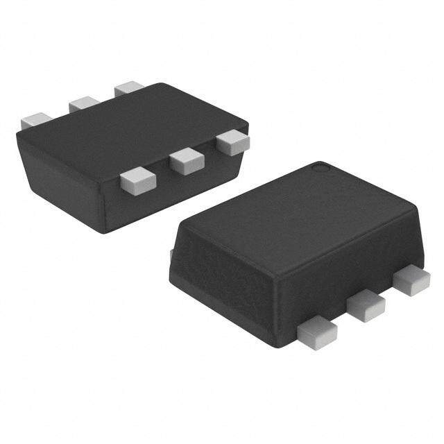
| 产品目录绘图 |
|
| 产品目录页面 | |
| 产品种类 | 变容二极管 |
| 供应商器件封装 | SOT-23-3 |
| 其它名称 | 863-1128-1 |
| 包装 | 剪切带 (CT) |
| 反向电压 | 12 V |
| 商标 | Skyworks Solutions, Inc. |
| 安装类型 | 表面贴装 |
| 封装 | Reel |
| 封装/外壳 | TO-236-3,SC-59,SOT-23-3 |
| 封装/箱体 | SOT-23 |
| 工厂包装数量 | 3000 |
| 最大工作温度 | + 125 C |
| 最小工作温度 | - 55 C |
| 标准包装 | 1 |
| 正向连续电流 | 20 mA |
| 电压-峰值反向(最大值) | 12V |
| 电容 | 18.1 pF |
| 电容比 | 5 |
| 电容比条件 | C1/C4 |
| 端接类型 | SMD/SMT |
| 配置 | Common Cathode |


PDF Datasheet 数据手册内容提取
DATA SHEET SMV121x Series: Hyperabrupt Junction Tuning Varactors Applications Low tuning voltage VCOs High-volume commercial systems Features High capacitance ratio: C1V/C4V = 5 typical Packages rated MSL1, 260 °C per JEDEC J-STD-020 Skyworks GreenTM products are compliant with Description all applicable legislation and are halogen-free. For additional information, refer to Skyworks The SMV121x series of silicon hyperabrupt junction varactor Definition of GreenTM, document number diodes are designed for use in Voltage Controlled Oscillators SQ04–0074. (VCOs) with a low tuning voltage operation. This family of varactors is characterized for capacitance and resistance over temperature. Table 1 describes the various packages and markings of the SMV121x varactors. Skyworks Solutions, Inc. • Phone [781] 376-3000 • Fax [781] 376-3100 • sales@skyworksinc.com • www.skyworksinc.com 200057T • Skyworks Proprietary Information • Products and Product Information are Subject to Change Without Notice • July 28, 2016 1
DATA SHEET • SMV121x VARACTORS Table 1. Packaging and Marking Single Single Common Cathode Single SC-79 SOT-23 SOT-23 SOD-882 Green™ Green™ SMV1212-079LF SMV1212-001LF Marking: Cathode and HA Green™ Marking: EB1 SMV1213-079LF ♦SMV1213-001LF SMV1213-004LF SMV1213-004LF Marking: Cathode and HC Green™ Green™ Marking: J Marking: D86 Marking: GD3 SMV1215-001LF Green™ Marking: DM1 LS = 0.7 nH LS = 1.5 nH LS = 1.4 nH LS = 0.45 nH The Pb-free symbol or “LF” in the part number denotes a lead-free, RoHS-compliant package unless otherwise noted as Green™. Tin/lead (Sn/Pb) packaging is not recommended for new designs. Electrical and Mechanical Specifications Package and Handling Information The absolute maximum ratings of the SMV121x varactors are Instructions on the shipping container label regarding exposure to provided in Table 2. Electrical specifications are provided in moisture after the container seal is broken must be followed. Table 3. Typical capacitance values are listed in Table 4. Typical Otherwise, problems related to moisture absorption may occur performance characteristics of the SMV121x varactors are when the part is subjected to high temperature during solder illustrated in Figures 1 through 4. assembly. The SPICE model for the SMV121x varactors is shown in Figure 5 The SMV121x series of varactors are rated to Moisture Sensitivity and the associated model parameters are provided in Table 6. Level 1 (MSL1) at 260 C. They can be used for lead or lead-free soldering. For additional information, refer to the Skyworks Application Note, Solder Reflow Information, document number Package Dimensions 200164. Package dimensions are shown in Figures 6 to 10 (even Care must be taken when attaching this product, whether it is numbers), and tape and reel dimensions are provided in Figures 7 done manually or in a production solder reflow environment. to 11 (odd numbers). Production quantities of this product are shipped in a standard tape and reel format. Skyworks Solutions, Inc. • Phone [781] 376-3000 • Fax [781] 376-3100 • sales@skyworksinc.com • www.skyworksinc.com 2 July 28, 2016 • Skyworks Proprietary Information • Products and Product Information are Subject to Change Without Notice • 200057T
DATA SHEET • SMV121x VARACTORS Table 2. SMV121x Varactors Absolute Maximum Ratings1 Parameter Symbol Minimum Maximum Units Reverse voltage VR 12 V Forward current IF 20 mA Power dissipation PDIS 250 mW Operating temperature TOP –55 +125 C Storage temperature TSTG –55 +150 C Electrostatic discharge: ESD Charged Device Model (CDM), Class 3 1000 V Human Body Model (HBM), Class 1B 500 V Machine Model (MM), Class A 100 V 1 Exposure to maximum rating conditions for extended periods may reduce device reliability. There is no damage to device with only one parameter set at the limit and all other parameters set at or below their nominal value. Exceeding any of the limits listed here may result in permanent damage to the device. ESD HANDLING: Although this device is designed to be as robust as possible, electrostatic discharge (ESD) can damage this device. This device must be protected at all times from ESD when handling or transporting. Static charges may easily produce potentials of several kilovolts on the human body or equipment, which can discharge without detection. Industry-standard ESD handling precautions should be used at all times. Table 3. SMV121x Varactors Electrical Specifications1 (TOP = 25 C, Unless Otherwise Noted) CT @ 1 V CT @ 1 V RS @ 4 V, CT @ 1 V CT @ 2.5 V CT @ 4 V CT @ 2.5 V CT @ 4 V 500 MHz (pF) (pF) (pF) (Ratio) (Ratio) (Ω) Part Number Min Typ Min Max Typ Max Typ Typ Typ SMV1212 42.0 50.0 18.0 27.0 9 12.0 2 5 0.8 SMV1213 17.0 22.0 8.5 10.5 4 5.5 2 5 1.4 SMV1214 14.5 16.0 6.5 7.8 3 4.8 2 5 1.7 SMV1215 8.7 9.5 4.3 5.5 2 2.9 2 5 2.8 1 Performance is guaranteed only under the conditions listed in this table. Reverse voltage Vr (Ir = 10 μA) = 12 V minimum Reverse current Ir (Vr = 8 V) = 20 nA maximum Skyworks Solutions, Inc. • Phone [781] 376-3000 • Fax [781] 376-3100 • sales@skyworksinc.com • www.skyworksinc.com 200057T • Skyworks Proprietary Information • Products and Product Information are Subject to Change Without Notice • July 28, 2016 3
DATA SHEET • SMV121x VARACTORS Table 4. Typical Capacitance Values CT (pF) VR (V) SMV1212 SMV1213 SMV1214 SMV1215 0 72.4 30.0 26.0 14.8 0.5 55.3 22.8 19.6 11.3 1.0 44.9 18.1 15.6 9.1 1.5 36.9 15.3 12.4 7.5 2.0 29.9 12.3 9.6 6.0 2.5 22.9 9.2 6.8 4.5 3.0 16.3 6.4 4.7 3.1 3.5 11.8 4.5 3.5 2.3 4.0 9.3 3.5 2.9 1.9 4.5 7.9 3.0 2.5 1.7 5.0 7.0 2.6 2.3 1.5 5.5 6.4 2.4 2.1 1.4 6.0 6.0 2.2 2.0 1.3 6.5 5.7 2.1 1.9 1.3 7.0 5.5 2.0 1.8 1.2 7.5 5.3 1.9 1.8 1.2 8.0 5.1 1.9 1.7 1.2 Skyworks Solutions, Inc. • Phone [781] 376-3000 • Fax [781] 376-3100 • sales@skyworksinc.com • www.skyworksinc.com 4 July 28, 2016 • Skyworks Proprietary Information • Products and Product Information are Subject to Change Without Notice • 200057T
DATA SHEET • SMV121x VARACTORS Typical Performance Characteristics 200057-001 200057-002 Figure 1. Capacitance vs Reverse Voltage Figure 2. Series Resistance vs Reverse Voltage @ 500 MHz +3 +15 +2 +10 %) VR = 1 V %) e ( +1 e ( +5 g g n n a a h h C 0 C 0 e e g g a a nt –1 nt –5 e e c c er er P ––32 VR = 4 V 200057-003 P ––1150 200057-004 –40 –20 0 +20 +40 +60 +80 –40 –20 0 +20 +40 +60 +80 Temperature (°C) Temperature (°C) Figure 3. Relative Capacitance Change vs Temperature Figure 4. Relative Series Resistance Change vs Temperature @ 500 MHz Skyworks Solutions, Inc. • Phone [781] 376-3000 • Fax [781] 376-3100 • sales@skyworksinc.com • www.skyworksinc.com 200057T • Skyworks Proprietary Information • Products and Product Information are Subject to Change Without Notice • July 28, 2016 5
DATA SHEET • SMV121x VARACTORS PORT P_anode port = 1 IND L = LLSS DIODEM FC = 0.5 Diode_Model BV = VB IS = 1.00e-14 IBV = 1e-3 RS = 0 ISR = 0 N = 1 NR = 2 R =R ERRSSS CCCAP =P CP CTMVJTJ O=== = MV0 JCJO ININKBBBFV LVV= L== =0 01 1 DIODE EG = 1.11 TBV1 = 0 Varactor_Diode XTI = 3 TNOM = 27 AREA = 1 KF =0 FFE = 1 MODEL = Diode_Model AF =1 MODE = nonlinear PORT P_Cathode port = 2 200057-005 Figure 5. SPICE Model Table 5. SPICE Model Parameters1 CJO VJ CP RS Part Number (pF) (V) M (pF) (Ω) SMV1212 72.47 110 67 4.5 0.8 SMV1213 28.90 190 105 2.2 1.4 SMV1214 22.74 190 106 1.5 1.7 SMV1215 14.36 190 115 1.1 2.8 1 Values extracted from measured performance. For package inductance (LS, refer to Table 1. For more details, refer to the Skyworks Application Note, Varactor SPICE Model for Approved RF VCO Applications, document number 200315. Skyworks Solutions, Inc. • Phone [781] 376-3000 • Fax [781] 376-3100 • sales@skyworksinc.com • www.skyworksinc.com 6 July 28, 2016 • Skyworks Proprietary Information • Products and Product Information are Subject to Change Without Notice • 200057T
DATA SHEET • SMV121x VARACTORS Box or Polarity Bar Indicator Area 0.006 (0.15 mm) Min 0.010 1 2 0.028 (0.25 mm) Min (0.70 mm) Min 0.014 0.035 (0.35 mm) Max (0.90 mm) Max 0.060 (1.50 mm) Min 0.067 (1.70 mm) Max 0.043 (1.10 mm) Min 0.051 (1.30 mm) Max 10° Max 0.020 (0.50 mm) Min 0.003 0.028 (0.07 mm) Min (0.70 mm) Max 0.008 (0.20 mm) Max 10° Max Dimensions are in inches (millimeters shown in parentheses) 200057-006 Figure 6. SC-79 Package Dimensions Ø1.50± 0.10 4.00 ± 0.10 4.00 ± 0.10 2.00 ± 0.05 0.229 ± 0.02 (T) B 1.75 ± 0.10 2° Max 1.95 ± 0.05 (Bo) 1.40 ± 0.05 A A 3.50 ± 0.05 8.00 ± 0.20 B Pin 1 Indicator 0.80 ± 0.05 (Ko) Ø0.50± 0.05 Section B 0.39 ± 0.05 2o Max 0.90 ± 0.05 (Ao) Section A Notes: 1. Carrier tape: black conductive polycarbonate or polystyrene. 2. Cover tape material: transparent conductive PSA. 3. Cover tape size: 5.4 mm width. 4. ESD-surface resistivity is ≤1 x 10⁸ Ohms/square per EIA, JEDEC TNR Specification. 200057-007 5. All measurements are in millimeters. Figure 7. SC-79 Tape and Reel Dimensions Skyworks Solutions, Inc. • Phone [781] 376-3000 • Fax [781] 376-3100 • sales@skyworksinc.com • www.skyworksinc.com 200057T • Skyworks Proprietary Information • Products and Product Information are Subject to Change Without Notice • July 28, 2016 7
DATA SHEET • SMV121x VARACTORS 0.110 (2.80 mm) Min 0.120 (3.04 mm) Max 0.012 (0.30 mm) Min 0.020 (0.50 mm) Max 3 0.083 (2.10 mm) Min 0.047 (1.20 mm) Min 0.104 (2.64 mm) Max 0.055 (1.40 mm) Max 1 2 0.037 (0.95 mm) Ref 0.020 (0.51 mm) Ref 0.076 (1.92 mm) Ref 0.035 (0.89 mm) Min 0.003 (0.080 mm) Min 0.044 (1.12 mm) Max 0.008 (0.20 mm) Max 8° Max. 0.0005 (0.01 mm) Min 0.004 (0.10 mm) Max 0.022 (0.55 mm) Ref Dimensions are in inches (millimeters shown in parentheses) 200057-008 Figure 8. SOT-23 Package Dimensions 4.00 2.00 ± 0.05 0.25 ± 0.05 ø1.00 Min ø1.5 + 0.1/–0 1.75 ± 0.10 4.00 A (See Note 5) 50 ± 0.05 + 0.3/–0.1 2.70 (Bo) 3. 0 0 8. R 0.3 Max 2.2 A 1.0 1.20 (Ko) R 0.5 Typ Pin 1 Indicator 3.10 (Ao) 0.8 ± 0.05 Section A Notes: 1. Carrier tape: black conductive polycarbonate. 2. Cover tape material: transparent conductive PSA. 3. Cover tape size: 5.40 mm width. 4. Tolerance ±0.10 mm. 5. Ten sprocket hole pitch cumulative tolerance: ±0.2 mm. 6. All measurements are in millimeters. 7. Alternative carrier tape dimensions are: Ao = 3.3 200057-009 Bo = 2.9 Ko = 1.22 Figure 9. SOT-23 Tape and Reel Dimensions Skyworks Solutions, Inc. • Phone [781] 376-3000 • Fax [781] 376-3100 • sales@skyworksinc.com • www.skyworksinc.com 8 July 28, 2016 • Skyworks Proprietary Information • Products and Product Information are Subject to Change Without Notice • 200057T
DATA SHEET • SMV121x VARACTORS 0.03 C Seating Plane 0.05/0.00 5 Pin 1 Indicator 2X 0.25 ± 0.05 C 2X 0.05 0.10 M A B 0.325 Terminal 1 1.000 0.650 B A 0.600 2X 0.50 ± 0.05 0.46 + 0.04 4 0.05 –0.06 0.10 M A B 2X Notes: 1. All measurements are in millimeters. 2. Dimensions and tolerances according to ASME Y14.5M-1994. 3. These packages are used principally for discrete devices. 4. This dimension includes stand-off height and package body thickness, but does not include attached features, e.g., external heatsink or chip capacitors. An integral heatslug is not considered an attached feature. 200057-010 5. This dimension is primarily terminal plating, but does not include small metal protrusion. Figure 10. SOD-882 Package Dimensions 2.00 ± 0.05 4.00 ± 0.10 ICnadtihcaotdoer ∅1.55 ± 0.05 (D0) 0.20 A 1.75 ± 0.10 5 ± 0.05 (Bo) 3.50 ± 0.0 8.00 ± 0.1 5 1.1 ∅0.40 ± 0.05 (D1) 0.47 ± 0.05 (Ko) B B A 2.00 ± 0.05 Section A 0.70 ± 0.05 (A0) Notes: 1. Carrier tape: black conductive polycarbonate. 2. Cover tape: transparent conductive material. 3. Cover tape size: 5.4 mm width. Section B 4. ESD surface resistivity is ≥1 x 10⁴ ~ ≤ 1 x 10⁸ Ohms/square. 200057-011 5. All dimensions are in millimeters. Figure 11. SOD-882 Tape and Reel Dimensions Skyworks Solutions, Inc. • Phone [781] 376-3000 • Fax [781] 376-3100 • sales@skyworksinc.com • www.skyworksinc.com 200057T • Skyworks Proprietary Information • Products and Product Information are Subject to Change Without Notice • July 28, 2016 9
DATA SHEET • SMV121x VARACTORS Copyright © 2002-2007, 2009-2016 Skyworks Solutions, Inc. All Rights Reserved. Information in this document is provided in connection with Skyworks Solutions, Inc. (“Skyworks”) products or services. These materials, including the information contained herein, are provided by Skyworks as a service to its customers and may be used for informational purposes only by the customer. Skyworks assumes no responsibility for errors or omissions in these materials or the information contained herein. Skyworks may change its documentation, products, services, specifications or product descriptions at any time, without notice. Skyworks makes no commitment to update the materials or information and shall have no responsibility whatsoever for conflicts, incompatibilities, or other difficulties arising from any future changes. No license, whether express, implied, by estoppel or otherwise, is granted to any intellectual property rights by this document. Skyworks assumes no liability for any materials, products or information provided hereunder, including the sale, distribution, reproduction or use of Skyworks products, information or materials, except as may be provided in Skyworks Terms and Conditions of Sale. THE MATERIALS, PRODUCTS AND INFORMATION ARE PROVIDED “AS IS” WITHOUT WARRANTY OF ANY KIND, WHETHER EXPRESS, IMPLIED, STATUTORY, OR OTHERWISE, INCLUDING FITNESS FOR A PARTICULAR PURPOSE OR USE, MERCHANTABILITY, PERFORMANCE, QUALITY OR NON-INFRINGEMENT OF ANY INTELLECTUAL PROPERTY RIGHT; ALL SUCH WARRANTIES ARE HEREBY EXPRESSLY DISCLAIMED. SKYWORKS DOES NOT WARRANT THE ACCURACY OR COMPLETENESS OF THE INFORMATION, TEXT, GRAPHICS OR OTHER ITEMS CONTAINED WITHIN THESE MATERIALS. SKYWORKS SHALL NOT BE LIABLE FOR ANY DAMAGES, INCLUDING BUT NOT LIMITED TO ANY SPECIAL, INDIRECT, INCIDENTAL, STATUTORY, OR CONSEQUENTIAL DAMAGES, INCLUDING WITHOUT LIMITATION, LOST REVENUES OR LOST PROFITS THAT MAY RESULT FROM THE USE OF THE MATERIALS OR INFORMATION, WHETHER OR NOT THE RECIPIENT OF MATERIALS HAS BEEN ADVISED OF THE POSSIBILITY OF SUCH DAMAGE. Skyworks products are not intended for use in medical, lifesaving or life-sustaining applications, or other equipment in which the failure of the Skyworks products could lead to personal injury, death, physical or environmental damage. Skyworks customers using or selling Skyworks products for use in such applications do so at their own risk and agree to fully indemnify Skyworks for any damages resulting from such improper use or sale. Customers are responsible for their products and applications using Skyworks products, which may deviate from published specifications as a result of design defects, errors, or operation of products outside of published parameters or design specifications. Customers should include design and operating safeguards to minimize these and other risks. Skyworks assumes no liability for applications assistance, customer product design, or damage to any equipment resulting from the use of Skyworks products outside of stated published specifications or parameters. Skyworks and the Skyworks symbol are trademarks or registered trademarks of Skyworks Solutions, Inc., in the United States and other countries. Third-party brands and names are for identification purposes only, and are the property of their respective owners. Additional information, including relevant terms and conditions, posted at www.skyworksinc.com, are incorporated by reference. Skyworks Solutions, Inc. • Phone [781] 376-3000 • Fax [781] 376-3100 • sales@skyworksinc.com • www.skyworksinc.com 10 July 28, 2016 • Skyworks Proprietary Information • Products and Product Information are Subject to Change Without Notice • 200057T
Mouser Electronics Authorized Distributor Click to View Pricing, Inventory, Delivery & Lifecycle Information: S kyworks: SMV1212-001LF SMV1213-004LF SMV1213-040LF SMV1213-079LF SMV1215-001LF SMV1214-001LF SMV1212-004LF SMV1213-001LF SMV1212-074LF SMV1212-079LF SMV1213-074LF