ICGOO在线商城 > SM802116UMG

 Datasheet下载
- 型号: SM802116UMG
- 制造商: Micrel
- 库位|库存: xxxx|xxxx
- 要求:
| 数量阶梯 | 香港交货 | 国内含税 |
| +xxxx | $xxxx | ¥xxxx |
查看当月历史价格
查看今年历史价格
SM802116UMG产品简介:
ICGOO电子元器件商城为您提供SM802116UMG由Micrel设计生产,在icgoo商城现货销售,并且可以通过原厂、代理商等渠道进行代购。 提供SM802116UMG价格参考以及MicrelSM802116UMG封装/规格参数等产品信息。 你可以下载SM802116UMG参考资料、Datasheet数据手册功能说明书, 资料中有SM802116UMG详细功能的应用电路图电压和使用方法及教程。
SM802116UMG 是 Microchip Technology 推出的一款高性能、低抖动时钟发生器(Clock Generator),集成 PLL 和分数分频频率合成器,采用 40 引脚 QFN 封装(UMG)。其典型应用场景包括:

- 通信基础设施:用于 5G 基站、光模块(如 SFP+/QSFP)、PTN/OTN 设备中,为 SerDes、FPGA、ASIC 提供多路低抖动参考时钟(支持 100 MHz、125 MHz、156.25 MHz 等常用速率),满足 IEEE 802.3、ITU-T G.8262 等抖动规范。

- 数据中心与高速互连:为 PCIe Gen4/Gen5、CXL、USB4、SATA/SAS 控制器提供可编程时钟源,支持动态频率切换与扩频调制(SSC),降低 EMI。

- 工业与嵌入式系统:在高端 PLC、医疗成像设备(如超声前端)、测试测量仪器(示波器、逻辑分析仪)中,为 ADC/DAC、FPGA 或 SoC 提供高精度、多相位同步时钟,支持 I²C 配置与故障监控(LOS、CLKOK 输出)。

- 汽车电子(车载信息娱乐及 ADAS):符合 AEC-Q100 Grade 2(–40°C 至 +105°C),适用于车载摄像头模组、域控制器等对时序稳定性要求严苛的场景。

该器件支持最多 6 路 LVDS/LVPECL/HCSL 差分输出或 12 路 LVCMOS 单端输出,具备优异的相位噪声(–156 dBc/Hz @ 1 MHz offset)和 RMS 抖动(< 150 fs),适合高带宽、低延迟系统。
| 参数 | 数值 |
| 产品目录 | 集成电路 (IC) |
| 描述 | IC SYNTHSZR 106.25/212.5MHZ 24QF |
| 产品分类 | |
| 品牌 | Micrel Inc |
| 数据手册 | |
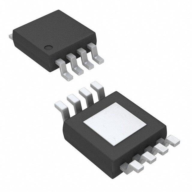
| 产品图片 |
|
| 产品型号 | SM802116UMG |
| PLL | 带旁路 |
| rohs | 无铅 / 符合限制有害物质指令(RoHS)规范要求 |
| 产品系列 | ClockWorks™, RotaryWave™ |
| 供应商器件封装 | 24-QFN(4x4) |
| 其它名称 | 576-3977 |
| 分频器/倍频器 | 是/无 |
| 包装 | 管件 |
| 安装类型 | 表面贴装 |
| 封装/外壳 | 24-VFQFN 裸露焊盘 |
| 工作温度 | -40°C ~ 85°C |
| 差分-输入:输出 | 无/是 |
| 标准包装 | 75 |
| 比率-输入:输出 | 2:2 |
| 电压-电源 | 2.375 V ~ 3.465 V |
| 电路数 | 1 |
| 类型 | 时钟/频率合成器 |
| 输入 | LVCMOS,晶体 |
| 输出 | LVDS |
| 频率-最大值 | 212.5MHz |
.jpg)


- 商务部:美国ITC正式对集成电路等产品启动337调查
- 曝三星4nm工艺存在良率问题 高通将骁龙8 Gen1或转产台积电
- 太阳诱电将投资9.5亿元在常州建新厂生产MLCC 预计2023年完工
- 英特尔发布欧洲新工厂建设计划 深化IDM 2.0 战略
- 台积电先进制程称霸业界 有大客户加持明年业绩稳了
- 达到5530亿美元!SIA预计今年全球半导体销售额将创下新高
- 英特尔拟将自动驾驶子公司Mobileye上市 估值或超500亿美元
- 三星加码芯片和SET,合并消费电子和移动部门,撤换高东真等 CEO
- 三星电子宣布重大人事变动 还合并消费电子和移动部门
- 海关总署:前11个月进口集成电路产品价值2.52万亿元 增长14.8%


PDF Datasheet 数据手册内容提取
SM802XXX Flexible Ultra-Low Jitter Clock Synthesizer Features General Description • 115fs at 156.25MHz (1.875MHz to 20MHz) The SM802xxx series is a member of the ClockWorks® • 265fs at 156.25MHz (12kHz to 20MHz) family of devices from Microchip and provide an extremely low-noise timing solution for applications • On-Chip Power Supply Regulation for Excellent such as (1-100) Gigabit Ethernet, SONET, wireless Board-Level Power Supply Noise Immunity base station, satellite communication, Fibre Channel, • Generates up to 8 Combinations of Differential or SAS/SATA, and PCIe. It is based upon a unique PLL 16 Single-Ended Clock Outputs architecture that provides less than 250fs phase jitter. - LVPECL, LVDS, HCSL, LVCMOS (SE or Diff) The devices operate from a 2.5V or 3.3V power supply • Selectable Input: and synthesize up to 8 different combinations - Crystal: 11.4MHz to 27MHz (LVPECL, LVDS, HCSL) of differential or 16 - Reference Input: 11.4MHz to 80MHz single-ended output clocks. The devices accept an • No External Crystal Oscillator Capacitors external reference clock or crystal input. Required The SM802xxx series is fully programmable and a web • 2.5V or 3.3V Operating Power Supply tool is available to configure a part for samples at the • Available in Industrial Temperature Range ClockWorks Configurator tool. • Available in Green, RoHS, and PFOS Compliant QFN Packages: - 44-pin, 7mm × 7mm - 32-pin, 5mm × 5mm - 24-pin, 4mm × 4mm - 16-pin, 3mm × 3.5mm Applications • 1/10/40/100 Gigabit Ethernet (GbE) • SONET/SDH • PCI Express • CPRI/OBSAI – Wireless Base Station • Fibre Channel • SAS/SATA • DIMM 2019 Microchip Technology Inc. DS20006176A-page 1
SM802XXX Package Types SM802XXX SM802XXX Option 1: 44-Pin 7mm x 7mm QFN Option 2: 32-Pin 5mm x 5mm QFN (Top View) (Top View) VDDO2VDDO2QE/QEVSSO2VSSO1VDDO1VDDO1QD/QDTEST VDDO2QE/QEVSSO2VSSO1VDDO1QD/QD 32 31 30 29 28 27 26 25 4443424140393837363534 /QF 1 33 QC VDDO2 1 24 TEST QF 2 32 /QC VSSO2 2 23 VDDO1 VSSO2 3 31 VDDO1 /QG 3 22 QB /QG 4 30 TEST QG 4 21 /QB QG 5 29 QB VSSO2 6 28 /QB PLL_BYPASS 5 20 TEST /QH 7 27 TEST XTAL_SEL 6 19 VSSO1 QH 8 26 QA TEST 7 18 VSS PLL_BYPASS 9 25 /QA VDD 8 17 VSS XTAL_SEL 10 24 VSSO1 TEST 11 23 VSS 9 10 11 12 13 14 15 16 1213141516171819202122 DL1NNTT2 VDDVDDFSELOE1DDO2EF_INXINXOUTTESTVSSOE2 VDFSEOEREF_IXIXOUTESOE VR SM802XXX SM802XXX Option 3: 24-Pin 4mm x 4mm QFN Option 4: 24-Pin 4mm x 4mm QFN (Top View) (Top View) QE /QE VSSO1 /QD QD TEST VDDO2 QE /QE VSSO1 QD /QD 24 23 22 21 20 19 24 23 22 21 20 19 VDDO2 1 18 VDDO1 VDD 1 18 TEST VSSO2 2 17 QB VSSO2 2 17 VDDO1 /QG 3 16 /QB PLL_BYPASS 3 16 TEST QG 4 15 TEST XTAL_SEL 4 15 VSS PLL_BYPASS 5 14 VSS TEST 5 14 VSS XTAL_SEL 6 13 VSS FSEL 6 13 VSS 7 8 9 10 11 12 7 8 9 10 11 12 TEST VDD REF_IN XIN XOUT TEST OE1 REF_IN XIN XOUT TEST OE2 SM802XXX SM802XXX Option 5: 16-Pin 3mm x 3.5mm QFN Option 6: 16-Pin 3mm x 3.5mm QFN (Top View) (Top View) 2 2 1/ 1/ VDDO QD /QD TEST VDDO QD /QD TEST 16 15 14 13 16 15 14 13 /QF 1 12 VSS /QF 1 12 VSS QF 2 11 TEST QF 2 11 TEST VSS 3 10 VSS VSS 3 10 VSS TEST 4 9 VSS TEST 4 9 VSS 5 6 7 8 5 6 7 8 D L N T D N T T VD FSE EF_I TES VD XI XOU TES R DS20006176A-page 2 2019 Microchip Technology Inc.
SM802XXX Block Diagram V V D D V V D D S D O O S D 2 1 VDD Power Rail Regulation QA 1 QB Div 1 QC ÷ 0 QD REFIN 0 PLL 1 QE XO 1 1 QF Div 2 ÷ QG XTAL_SEL 0 INTERNAL PULL-UP QH P UIN LT INTERNAL L-DER ON PULL-UPS WA NL F O O P V V S E E L S S E 2 1 L S S L _B O O Y 2 1 P A S S 2019 Microchip Technology Inc. DS20006176A-page 3
SM802XXX 1.0 ELECTRICAL CHARACTERISTICS Absolute Maximum Ratings † Supply Voltage (V , V ).................................................................................................................................+4.6V DD DDO1/2 Input Voltage (V ).............................................................................................................................–0.5V to V + 0.5V IN DD Operating Ratings †† Supply Voltage (V , V )..........................................................................................................+2.375V to +3.465V DD DDO1/2 † Notice: Exceeding the absolute maximum ratings may damage the device. †† Notice: The data sheet limits are not guaranteed if the device is operated beyond the operating ratings. DC ELECTRICAL CHARACTERISTICS (Note 1) Electrical Characteristics: V = V = 3.3V ±5% or 2.5V ±5%; V = 3.3V ±5%, V = 3.3V ±5% or 2.5V DD DDO1/2 DD DDO1/2 ±5%; T = –40°C to +85°C. A Parameter Symbol Min. Typ. Max. Units Conditions 3.3V Operating Voltage V 3.135 3.3 3.465 DD, V V = V 2.5V Operating Voltage VDDO1/2 2.375 2.5 2.625 DDO1 DDO2 8 LVPECL, 312.5MHz (44-pin QFN) — 275 345 Outputs open 4 HCSL (PCIe), 100MHz (32-pin or Total Supply Current, — 150 185 24-pin QFN) I mA V + V DD Outputs 50Ω to V DD DDO SS 2 LVCMOS, 125MHz — 70 90 (16-pin QFN) Outputs open Note 1: The circuit is designed to meet the AC and DC specifications shown in the Electrical Characteristics tables after thermal equilibrium has been established. LVCMOS INPUTS (OE1, OE2, PLL_BYPASS, XTAL_SEL, FSEL) DC ELECTRICAL CHARACTERISTICS (Note 1) Electrical Characteristics: V = 3.3V ±5% or 2.5V ±5%; T = –40°C to +85°C. DD A Parameter Symbol Min. Typ. Max. Units Conditions Input High Voltage V 2 — V + V — IH DD 0.3 Input Low Voltage V –0.3 — 0.8 V — IL Input High Current I — — 150 µA V = V = 3.465V IH DD IN Input Low Current I –150 — — µA V = 3.465V, V = 0V IL DD IN Note 1: The circuit is designed to meet the AC and DC specifications shown in the Electrical Characteristics tables after thermal equilibrium has been established. DS20006176A-page 4 2019 Microchip Technology Inc.
SM802XXX LVDS OUTPUT DC ELECTRICAL CHARACTERISTICS (Note 1) Electrical Characteristics: V = V = 3.3V ±5% or 2.5V ±5%; V = 3.3V ±5%, V = 3.3V ±5% or 2.5V DD DDO1/2 DD DDO1/2 ±5%; T = –40°C to +85°C. R = 100Ω across Q1 and /Q1. A L Parameter Symbol Min. Typ. Max. Units Conditions Differential Output Voltage V 275 350 475 mV Figure5-8 OD V Magnitude Change ∆V — — 40 mV — OD OD Offset Voltage V 1.15 1.25 1.50 V — OS V Magnitude Change ∆V — — 50 mV — OS OS Note 1: The circuit is designed to meet the AC and DC specifications shown in the Electrical Characteristics tables after thermal equilibrium has been established. HCSL OUTPUT DC ELECTRICAL CHARACTERISTICS (Note 1) Electrical Characteristics: V = V = 3.3V ±5% or 2.5V ±5%; V = 3.3V ±5%, V = 3.3V ±5% or 2.5V DD DDO1/2 DD DDO1/2 ±5%; T = –40°C to +85°C. R = 50Ω to V . A L SS Parameter Symbol Min. Typ. Max. Units Conditions Output High Voltage V 660 700 850 mV — OH Output Low Voltage V –150 0 27 mV — OL Output Voltage Swing V 250 350 550 mV — SWING Note 1: The circuit is designed to meet the AC and DC specifications shown in the Electrical Characteristics tables after thermal equilibrium has been established. LVPECL OUTPUT DC ELECTRICAL CHARACTERISTICS (Note 1) Electrical Characteristics: V = V = 3.3V ±5% or 2.5V ±5%; V = 3.3V ±5%, V = 3.3V ±5% or 2.5V DD DDO1/2 DD DDO1/2 ±5%; T = –40°C to +85°C. R = 50Ω to V –2V. A L DDO Parameter Symbol Min. Typ. Max. Units Conditions Output High Voltage V V – V – V – V — OH DDO DDO DDO 1.145 0.97 0.845 Output Low Voltage V V – V – V – V — OL DDO DDO DDO 1.945 1.77 1.645 Output Voltage Swing V 0.6 0.8 1.0 V — SWING Note 1: The circuit is designed to meet the AC and DC specifications shown in the Electrical Characteristics tables after thermal equilibrium has been established. LVCMOS OUTPUT DC ELECTRICAL CHARACTERISTICS (Note 1) Electrical Characteristics: V = V = 3.3V ±5% or 2.5V ±5%; V = 3.3V ±5%, V = 3.3V ±5% or 2.5V DD DDO1/2 DD DDO1/2 ±5%; T = –40°C to +85°C. R = 50Ω to V /2. A L DDO Parameter Symbol Min. Typ. Max. Units Conditions Output High Voltage V V – — — V Figure5-9 OH DDO 0.7 Output Low Voltage V — — 0.6 V Figure5-9 OL Note 1: The circuit is designed to meet the AC and DC specifications shown in the Electrical Characteristics tables after thermal equilibrium has been established. 2019 Microchip Technology Inc. DS20006176A-page 5
SM802XXX REF_IN DC ELECTRICAL CHARACTERISTICS (Note 1) Electrical Characteristics: V = 3.3V ±5% or 2.5V ±5%; T = –40°C to +85°C. DD A Parameter Symbol Min. Typ. Max. Units Conditions Input High Voltage V 1.1 — V + V — IH DD 0.3 Input Low Voltage V –0.3 — 0.6 V — IL Input Current I –5 — 5 µA XTAL_SEL = V , V = 0V to V IN IL IN DD — 20 — µA XTAL_SEL = V , V = V IH IN DD Note 1: The circuit is designed to meet the AC and DC specifications shown in the Electrical Characteristics tables after thermal equilibrium has been established. CRYSTAL CHARACTERISTICS Electrical Characteristics: V = 3.3V ±5% or 2.5V ±5%; T = –40°C to +85°C. DD A Parameter Min. Typ. Max. Units Conditions Mode of Oscillation Fundamental, parallel — 10pF load capacitance resonant Frequency 11.4 — 27 MHz — Equivalent Series Resistance (ESR) — — 30 Ω — Shunt Capacitance, C0 — 2 5 pF — Correlation Drive Level — 10 100 µW — LVPECL AC ELECTRICAL CHARACTERISTICS (Note 1, Note 2, Note 3, Note 4) Electrical Characteristics: V = V = 3.3V ±5% or 2.5V ±5%, V = 2.5V or 3.3V ±5%, T = –40°C to +85°C, DDA DD DDO A unless otherwise noted. Parameter Symbol Min. Typ. Max. Units Conditions Output Frequency F 11 — 840 MHz — OUT LVPECL Output Rise/Fall t/t 80 175 350 ps 20% - 80% r f Time Output Duty Cycle ODC 48 50 52 % < 350MHz 45 50 55 % ≥ 350MHz Output-to-Output Skew T — — 45 ps Note5 SKEW PLL Lock Time T — — 20 ms — LOCK RMS Phase Jitter @ T — 265 — fs Integration Range (12kHz to jit(Ø) 156.25MHz 20MHz) — 115 — fs Integration Range (1.875MHz to 20MHz) Note 1: The circuit is designed to meet the AC and DC specifications shown in the Electrical Characteristics tables after thermal equilibrium has been established. 2: See Figure5-6 through Figure5-9 for load test circuit examples. 3: All phase noise measurements were taken with an Agilent 5052B phase noise system. 4: Output load is 50Ω to V – 2V. DD 5: Defined as skew between outputs at the same supply voltage and with equal load conditions; Measured at the output differential crossing points. DS20006176A-page 6 2019 Microchip Technology Inc.
SM802XXX LVDS AC ELECTRICAL CHARACTERISTICS (Note 1, Note 2, Note 3, Note 4) Electrical Characteristics: V = V = 3.3V ±5% or 2.5V ±5%, V = 2.5V or 3.3V ±5%, T = –40°C to +85°C, DDA DD DDO A unless otherwise noted. Parameter Symbol Min. Typ. Max. Units Conditions Output Frequency F 11.4 — 840 MHz — OUT LVDS Output Rise/Fall t/t 100 160 400 ps 20% - 80% r f Time Output Duty Cycle ODC 48 50 52 % < 350MHz 45 50 55 % ≥ 350MHz Output-to-Output Skew T — — 45 ps Note5 SKEW PLL Lock Time T — — 20 ms — LOCK RMS Phase Jitter @ T — 110 — fs Integration Range (1.875MHz to jit(Ø) 156.25MHz 20MHz) Note 1: The circuit is designed to meet the AC and DC specifications shown in the Electrical Characteristics tables after thermal equilibrium has been established. 2: See Figure5-6 through Figure5-9 for load test circuit examples. 3: All phase noise measurements were taken with an Agilent 5052B phase noise system. 4: Outputs terminated 100Ω between Q and /Q. All unused outputs must be terminated. 5: Defined as skew between outputs at the same supply voltage and with equal load conditions; Measured at the output differential crossing points. HCSL AC ELECTRICAL CHARACTERISTICS (Note 1, Note 2, Note 3, Note 4) Electrical Characteristics: V = V = 3.3V ±5% or 2.5V ±5%, V = 2.5V or 3.3V ±5%, T = –40°C to +85°C, DDA DD DDO A unless otherwise noted. Parameter Symbol Min. Typ. Max. Units Conditions Output Frequency F 11.4 — 840 MHz — OUT Output Rise/Fall Time t/t 150 300 450 ps 20% - 80% r f Output Duty Cycle ODC 48 50 52 % < 350MHz 45 50 55 % ≥ 350MHz Output-to-Output Skew T — — 50 ps Note5 SKEW PLL Lock Time T — — 20 ms — LOCK RMS Phase Jitter @ T — 265 — fs Integration Range (12kHz to jit(Ø) 100MHz 20MHz) — 115 — fs Integration Range (1.875MHz to 20MHz) Note 1: The circuit is designed to meet the AC and DC specifications shown in the Electrical Characteristics tables after thermal equilibrium has been established. 2: See Figure5-6 through Figure5-9 for load test circuit examples. 3: All phase noise measurements were taken with an Agilent 5052B phase noise system. 4: Output load is 50Ω to V / 2. DD 5: Defined as skew between outputs at the same supply voltage and with equal load conditions; Measured at the output differential crossing points. 2019 Microchip Technology Inc. DS20006176A-page 7
SM802XXX LVCMOS AC ELECTRICAL CHARACTERISTICS (Note 1, Note 2, Note 3, Note 4) Electrical Characteristics: V = V = 3.3V ±5% or 2.5V ±5%, V = 2.5V or 3.3V ±5%, T = –40°C to +85°C, DDA DD DDO A unless otherwise noted. Parameter Symbol Min. Typ. Max. Units Conditions Output Frequency F 11.4 — 250 MHz — OUT REF_IN Frequency F 11 — 80 MHz — REF Output Rise/Fall Time t/t 100 — 500 ps 20% - 80% r f Output Duty Cycle ODC 45 50 55 % — Output-to-Output Skew T — — 60 ps Note5 SKEW PLL Lock Time T — — 20 ms — LOCK RMS Phase Jitter @ T — 115 — fs Integration Range (1.875MHz to jit(Ø) 125MHz 20MHz) Note 1: The circuit is designed to meet the AC and DC specifications shown in the Electrical Characteristics tables after thermal equilibrium has been established. 2: See Figure5-6 through Figure5-9 for load test circuit examples. 3: All phase noise measurements were taken with an Agilent 5052B phase noise system. 4: Output load is 50Ω to V / 2. DD 5: Defined as skew between outputs at the same supply voltage and with equal load conditions; Measured at the output differential crossing points. DS20006176A-page 8 2019 Microchip Technology Inc.
SM802XXX TEMPERATURE SPECIFICATIONS Parameters Sym. Min. Typ. Max. Units Conditions Temperature Ranges Ambient Temperature Range T –40 — +85 °C — A Lead Temperature — — — +260 °C Soldering, 20s Case Temperature — — — +115 °C — Storage Temperature Range T –65 — +150 °C — S Package Thermal Resistances (Note1) Junction Thermal Resistance, 7 x 7 — 24 — °C/W — QFN-44Ld JA Junction Thermal Resistance, 5 x 5 — 34 — °C/W — QFN-32Ld JA Junction Thermal Resistance, 4 x 4 θ — 50 — °C/W — QFN-24Ld JA Junction Thermal Resistance, 3 x 3.5 θ — 60 — °C/W — QFN-16Ld JA Note 1: Package thermal resistance assumes the exposed pad is soldered (or equivalent) to the device’s most negative potential on the PCB. 2019 Microchip Technology Inc. DS20006176A-page 9
SM802XXX 2.0 PIN DESCRIPTIONS The descriptions of the pins are listed in Table2-1. TABLE 2-1: PIN FUNCTION TABLE Pin Numbers by Package Option Pin Pin Pin Type Pin Function #1 #2 #3 #4 #5 #6 Name Level 44-pin 32-pin 24-pin 24-pin 16-pin 16-pin 18 13 10 9 — 6 XIN I,O (SE) — Crystal connections. 19 14 11 10 — 7 XOUT 17 12 9 8 7 — REF_IN I, (SE) LVCMOS Reference clock input. Frequency Select, divides output frequencies by 2. 14 10 — 6 6 — FSEL I, (SE) LVCMOS 0 = FREQ, 1 = FREQ/2, 45kΩ pull-up XTAL Select, selects between XTAL XTAL and REF_IN 10 6 6 4 — — I, (SE) LVCMOS SEL 0 = REF_IN, 1 = XTAL, 45kΩ pull-up Bypasses the PLL and switches the XTAL or REF_IN frequency PLL to all outputs 9 5 5 3 — — I, (SE) LVCMOS BYPASS 0 = PLL mode, 1 = Bypass mode, 45kΩ pull-down 25 — — — — — /QA O Various 26 — — — — — QA 28 21 16 — — — /QB Clock Outputs from Bank 1 O Various Each output can be 29 22 17 — — — QB programmed to its own logic 32 — — — — — /QC O Various type: LVPECL, LVDS, HCSL, or 33 — — — — — QC LVCMOS (Note1) 35 25 20 19 14 14 /QD O Various 36 26 21 20 15 15 QD 41 30 23 22 — — /QE O Various 42 31 24 23 — — QE 1 — — — 1 1 /QF Clock Outputs from Bank 2 O Various Each output can be 2 — — — 2 2 QF programmed to its own logic 4 3 3 — — — /QG O Various type: LVPECL, LVDS, HCSL, or 5 4 4 — — — QG LVCMOS (Note1) 7 — — — — — /QH O Various 8 — — — — — QH 31 23 18 17 16 16 Power Supply for the outputs on 37 27 — — — — V PWR — DDO1 Bank 1. 38 — — — — — 16 1 1 24 16 16 Power Supply for the outputs on 43 32 — — — — V PWR — DDO2 Bank 2. 44 — — — — — 24 19 22 21 — — Power Supply Ground for the V PWR — 39 28 — — — — SSO1 outputs on Bank 1. DS20006176A-page 10 2019 Microchip Technology Inc.
SM802XXX TABLE 2-1: PIN FUNCTION TABLE (CONTINUED) Pin Numbers by Package Option Pin Pin Pin Type Pin Function #1 #2 #3 #4 #5 #6 Name Level 44-pin 32-pin 24-pin 24-pin 16-pin 16-pin 3 2 2 2 — — Power Supply Ground for the 6 29 — — — — V PWR — SSO2 outputs on Bank 2. 40 — — — — — 11 7 7 5 4 4 20 15 12 11 8 8 Used for production test. 27 20 15 16 11 11 TEST — — Do not connect anything to 30 24 19 18 13 13 these pins. 34 — — — — — 12 8 8 1 5 5 V PWR — Core power supply. DD 13 9 — — — — 21 17 13 13 3 3 23 18 14 14 9 9 V PWR — Core power supply ground. SS — — — 15 10 10 — — — — 12 12 The exposed pad must be — — — — — — EPAD — — connected to the V ground SS plane. Output Enable 1, OUT1–8 disables to tri-state, 15 11 — 7 — — OE1 I, (SE) LVCMOS 0 = Disabled, 1 = Enabled, 45kΩ pull-up Output Enable 2, OUT9–16 disables to tri-state, 22 16 — 12 — — OE2 I, (SE) LVCMOS 0 = Disabled, 1 = Enabled, 45kΩ pull-up Note 1: In the case of LVCMOS, an output pair can provide two single-ended LVCMOS outputs. TABLE 2-2: TRUTH TABLE Internal Resistor Control Pin 0 Level (Low) 1 Level (High) (Note1) OE1 Pull-Up Outputs QA~QD disabled to Hi Z Outputs QA~QD enabled (Tri-State) OE2 Pull-Up Outputs QE~QH disabled to Hi Z Outputs QE~QH enabled (Tri-State) XTAL_SEL Pull-Up External reference clock input is Crystal is selected selected FSEL; (Note2) Pull-Up Output = Target Frequency x2 or /2 Output = Target Frequency PLL_BYPASS Pull-Down PLL frequency is connected to outputs PLL is bypassed, Crystal or Ref-in is connected to outputs Note 1: The internal resistor sets the default logic level on the control pin when the pin is left open. Pull up will set default logic 1 and pull down will set default logic 0. When the pin is not available on a specific configura- tion, the level will be the default logic level. 2: The FSEL pin behavior can be programmed between two types: - At FSEL=0 (low), the output frequency changes to multiply by 2. - At FSEL=0 (low), the output frequency changes to divide by 2. The FSEL function affects all outputs the same way, all outputs change when the FSEL pin level changes. 2019 Microchip Technology Inc. DS20006176A-page 11
SM802XXX 3.0 PHASE NOISE PLOTS FIGURE 3-1: 100MHz HCSL, 254fs for 12kHz to 20MHz Integration Range. RMS FIGURE 3-2: 125MHz LVCMOS, 114fs for 1.875MHz to 20MHz Integration Range. RMS DS20006176A-page 12 2019 Microchip Technology Inc.
SM802XXX FIGURE 3-3: 156.25MHz LVPECL, 245fs for 12kHz to 20MHz Integration Range. RMS FIGURE 3-4: 644.53125MHz LVDS, 293fs for 12kHz to 20MHz Integration Range. RMS 2019 Microchip Technology Inc. DS20006176A-page 13
SM802XXX 4.0 APPLICATION INFORMATION 4.1 Input Reference When operating with a crystal input reference, do not apply a switching signal to REF_IN. 4.2 Crystal Layout Keep the layers under the crystal as open as possible and do not place switching signals or noisy supplies under the crystal. Crystal load capacitance is built inside the die, so no external capacitance is needed. See the Microchip application note ANTC207 for further details. 4.3 Power Supply Decoupling Place the smallest value decoupling capacitor (4.7nF above) between the V and V pins, as close as DD SS possible to those pins and at the same side of the PCB as the IC. The shorter the physical path from V to DD capacitor and back from capacitor to V , the more SS effective the decoupling. Use one 4.7nF capacitor for each V pin on the SM802xxx. DD The impedance value of the ferrite bead (FB) needs to be between 80Ω and 240Ω with a saturation current ≥150mA. The V and V pins connect directly to the V DDO1 DDO2 DD plane. All V pins on the SM802xxx connect to V DD DD after the power supply filter. 4.4 Output Traces Design the traces for the output signals according to the output logic requirements. If LVCMOS is unterminated, add a 30Ω resistor in series with the output, as close as possible to the output pin, and start a 50Ω trace on the other side of the resistor. For differential traces, you can either use a differential design or two separate 50Ω traces. For EMI reasons, it is better to use a differential design. LVDS can be AC-coupled or DC-coupled to its termination. DS20006176A-page 14 2019 Microchip Technology Inc.
SM802XXX 5.0 POWER SUPPLY FILTERING RECOMMENDATIONS RIPPLE VDD PLANE VDD BLOCKER 1μF 1μF 0.01μF 4.7nF FIGURE 5-1: Preferred Filter, Using the MIC94300 or MIC94310 Ripple Blocker. FB 0.5(cid:159) VDD PLANE VDD 10μF 0.047μF 0.01μF 4.7nF FIGURE 5-2: Alternative, Traditional Filter, Using a Ferrite Bead. T 2V ODC= 1 ×100% T VDD, VDDA, VDDO 2 T OSCILLOSCOPE 2 Q T 1 V Q0 Z0 = 50(cid:159) OH /Q V SWING 50(cid:159) V GND OL nQ0 –1.3V or –0.5V FIGURE 5-3: Duty Cycle Timing. FIGURE 5-6: LVPECL Output Load and Test Circuit. 80% VDDO 20% OSCILLOSCOPE T T R F Q FIGURE 5-4: All Outputs Rise/Fall Time. Z0 = 50(cid:159) /Q RMS PHASE NOISE/JITTER 50(cid:159) VSS R E PHASE NOISE PLOT W O P SE FIGURE 5-7: HCSL Output Load and Test NOI PHASE NOISE MASK Circuit. f f 1 2 OFFSET FREQUENCY RMS JITTER = (cid:165)AREA UNDER THE MASKED PHASE NOISE PLOT FIGURE 5-5: RMS Phase/Noise/Jitter. 2019 Microchip Technology Inc. DS20006176A-page 15
SM802XXX VDD = VDDA = 3.3V VDDO = 2.5V or 3.3V Q0 Z0 = 50(cid:159) 100(cid:159) /Q0 GND FIGURE 5-8: LVDS Output Load and Test Circuit. +VDDO/2 VDDO OSCILLOSCOPE Q Z0 = 50(cid:159) 50(cid:159) VSS –VDDO/2 FIGURE 5-9: LVCMOS Output Load and Test Circuit. XTAL_IN 10pF PARALLEL CRYSTAL XTAL_OUT FIGURE 5-10: Crystal Input Interface. DS20006176A-page 16 2019 Microchip Technology Inc.
SM802XXX 6.0 PACKAGING INFORMATION 44-Lead QFN Package Outline and Recommended Land Pattern Note: For the most current package drawings, please see the Microchip Packaging Specification located at http://www.microchip.com/packaging. 2019 Microchip Technology Inc. DS20006176A-page 17
SM802XXX 32-Lead QFN Package Outline and Recommended Land Pattern Note: For the most current package drawings, please see the Microchip Packaging Specification located at http://www.microchip.com/packaging. DS20006176A-page 18 2019 Microchip Technology Inc.
SM802XXX 24-Lead QFN Package Outline and Recommended Land Pattern Note: For the most current package drawings, please see the Microchip Packaging Specification located at http://www.microchip.com/packaging. 2019 Microchip Technology Inc. DS20006176A-page 19
SM802XXX 16-Lead QFN Package Outline and Recommended Land Pattern Note: For the most current package drawings, please see the Microchip Packaging Specification located at http://www.microchip.com/packaging. DS20006176A-page 20 2019 Microchip Technology Inc.
SM802XXX APPENDIX A: REVISION HISTORY Revision A (March 2019) • Converted Micrel document SM802xxx to Micro- chip data sheet DS20006176A. • Minor text changes throughout. • Updated the Crystal and Reference Input fre- quency ranges in the Features section and in Crystal Characteristics table. • Updated ESR value in Crystal Characteristics table. • Updated the 12kHz to 20MHz Phase Jitter to 265fs in the Features and in LVPECL AC Electri- cal Characteristics (Note1, Note2, Note3, Note4). • Updated Output Frequency minimum and typical Phase Jitter in LVDS AC Electrical Characteristics (Note1, Note2, Note3, Note4), HCSL AC Elec- trical Characteristics (Note1, Note2, Note3, Note4), and LVCMOS AC Electrical Characteris- tics (Note1, Note2, Note3, Note4). • Corrected the impedance values for using a ferrite bead in Power Supply Decoupling section. 2019 Microchip Technology Inc. DS20006176A-page 21
SM802XXX NOTES: DS20006176A-page 22 2019 Microchip Technology Inc.
SM802XXX PRODUCT IDENTIFICATION SYSTEM To order or obtain information, e.g., on pricing or delivery, contact your local Microchip representative or sales office. Examples: PART NO. X X X - X a) SM802xxxUMG: Flexible Ultra-Low Jitter Clock Device Voltage Package Temperature Special Synthesizer, 2.5V/3.3V Voltage Type Processing Option, QFN Package, –40°C to Option +85°C Temperature Range, Tray b) SM802xxxUMG-TR: Flexible Ultra-Low Jitter Clock Device: SM802xxx: Flexible Ultra-Low Jitter Clock Synthesizer Synthesizer, 2.5V/3.3V Voltage Option, QFN Package, –40°C to Voltage Option: U = 2.5V/3.3V +85°C Temperature Range, Tape & Reel Package Type: M = 44-, 32-, 24-, or 16-QFN; see the Package Options Table (Note1). Temperature: G = –40°C to +85°C (NiPdAu Lead Free) Special Blank = Tray Processing: TR = Tape and Reel Package Options Table (Note1) Package QFN # of OE1 PLL XTAL REF_IN XTAL_SEL FSEL Option Package Outputs OE2 BYPASS #1 44-Pin 7x7 8 Diff. Yes Yes Yes Yes Yes Yes #2 32-Pin 5x5 4 Diff. Yes Yes Yes Yes Yes Yes #3 24-Pin 4x4 4 Diff. Yes Yes Yes No No Yes #4 24-Pin 4x4 2 Diff. Yes Yes Yes Yes Yes Yes #5 16-Pin 3x3.5 2 Diff. No Yes No Yes No No #6 16-Pin 3x3.5 2 Diff. Yes No No No No No Note 1: Use the web tool at http://clockworks.microchip.com/micrel/ to determine the desired configuration. 2019 Microchip Technology Inc. DS20006176A-page 23
SM802XXX NOTES: DS20006176A-page 24 2019 Microchip Technology Inc.
Note the following details of the code protection feature on Microchip devices: • Microchip products meet the specification contained in their particular Microchip Data Sheet. • Microchip believes that its family of products is one of the most secure families of its kind on the market today, when used in the intended manner and under normal conditions. • There are dishonest and possibly illegal methods used to breach the code protection feature. All of these methods, to our knowledge, require using the Microchip products in a manner outside the operating specifications contained in Microchip’s Data Sheets. Most likely, the person doing so is engaged in theft of intellectual property. • Microchip is willing to work with the customer who is concerned about the integrity of their code. • Neither Microchip nor any other semiconductor manufacturer can guarantee the security of their code. Code protection does not mean that we are guaranteeing the product as “unbreakable.” Code protection is constantly evolving. We at Microchip are committed to continuously improving the code protection features of our products. Attempts to break Microchip’s code protection feature may be a violation of the Digital Millennium Copyright Act. If such acts allow unauthorized access to your software or other copyrighted work, you may have a right to sue for relief under that Act. Information contained in this publication regarding device Trademarks applications and the like is provided only for your convenience The Microchip name and logo, the Microchip logo, AnyRate, AVR, and may be superseded by updates. It is your responsibility to AVR logo, AVR Freaks, BitCloud, chipKIT, chipKIT logo, ensure that your application meets with your specifications. CryptoMemory, CryptoRF, dsPIC, FlashFlex, flexPWR, Heldo, MICROCHIP MAKES NO REPRESENTATIONS OR JukeBlox, KeeLoq, Kleer, LANCheck, LINK MD, maXStylus, WARRANTIES OF ANY KIND WHETHER EXPRESS OR maXTouch, MediaLB, megaAVR, MOST, MOST logo, MPLAB, IMPLIED, WRITTEN OR ORAL, STATUTORY OR OptoLyzer, PIC, picoPower, PICSTART, PIC32 logo, Prochip OTHERWISE, RELATED TO THE INFORMATION, Designer, QTouch, SAM-BA, SpyNIC, SST, SST Logo, INCLUDING BUT NOT LIMITED TO ITS CONDITION, SuperFlash, tinyAVR, UNI/O, and XMEGA are registered QUALITY, PERFORMANCE, MERCHANTABILITY OR trademarks of Microchip Technology Incorporated in the U.S.A. FITNESS FOR PURPOSE. Microchip disclaims all liability and other countries. arising from this information and its use. Use of Microchip ClockWorks, The Embedded Control Solutions Company, devices in life support and/or safety applications is entirely at EtherSynch, Hyper Speed Control, HyperLight Load, IntelliMOS, the buyer’s risk, and the buyer agrees to defend, indemnify and mTouch, Precision Edge, and Quiet-Wire are registered hold harmless Microchip from any and all damages, claims, trademarks of Microchip Technology Incorporated in the U.S.A. suits, or expenses resulting from such use. No licenses are Adjacent Key Suppression, AKS, Analog-for-the-Digital Age, Any conveyed, implicitly or otherwise, under any Microchip Capacitor, AnyIn, AnyOut, BodyCom, CodeGuard, intellectual property rights unless otherwise stated. CryptoAuthentication, CryptoAutomotive, CryptoCompanion, CryptoController, dsPICDEM, dsPICDEM.net, Dynamic Average Matching, DAM, ECAN, EtherGREEN, In-Circuit Serial Programming, ICSP, INICnet, Inter-Chip Connectivity, JitterBlocker, KleerNet, KleerNet logo, memBrain, Mindi, MiWi, motorBench, MPASM, MPF, MPLAB Certified logo, MPLIB, MPLINK, MultiTRAK, NetDetach, Omniscient Code Generation, PICDEM, PICDEM.net, PICkit, PICtail, PowerSmart, PureSilicon, QMatrix, REAL ICE, Ripple Blocker, SAM-ICE, Serial Quad I/O, SMART-I.S., SQI, SuperSwitcher, SuperSwitcher II, Total Endurance, TSHARC, USBCheck, VariSense, ViewSpan, WiperLock, Wireless DNA, and ZENA are trademarks of Microchip Technology Incorporated in the U.S.A. and other countries. Microchip received ISO/TS-16949:2009 certification for its worldwide SQTP is a service mark of Microchip Technology Incorporated in headquarters, design and wafer fabrication facilities in Chandler and the U.S.A. Tempe, Arizona; Gresham, Oregon and design centers in California and India. The Company’s quality system processes and procedures Silicon Storage Technology is a registered trademark of Microchip are for its PIC® MCUs and dsPIC® DSCs, KEELOQ® code hopping Technology Inc. in other countries. devices, Serial EEPROMs, microperipherals, nonvolatile memory and GestIC is a registered trademark of Microchip Technology analog products. In addition, Microchip’s quality system for the design and manufacture of development systems is ISO 9001:2000 certified. Germany II GmbH & Co. KG, a subsidiary of Microchip Technology Inc., in other countries. All other trademarks mentioned herein are property of their QUALITY MANAGEMENT SYSTEM respective companies. © 2019, Microchip Technology Incorporated, All Rights Reserved. CERTIFIED BY DNV ISBN: 978-1-5224-4300-1 == ISO/TS 16949 == 2019 Microchip Technology Inc. DS20006176A-page 25
Worldwide Sales and Service AMERICAS ASIA/PACIFIC ASIA/PACIFIC EUROPE Corporate Office Australia - Sydney India - Bangalore Austria - Wels 2355 West Chandler Blvd. Tel: 61-2-9868-6733 Tel: 91-80-3090-4444 Tel: 43-7242-2244-39 Chandler, AZ 85224-6199 Fax: 43-7242-2244-393 China - Beijing India - New Delhi Tel: 480-792-7200 Tel: 86-10-8569-7000 Tel: 91-11-4160-8631 Denmark - Copenhagen Fax: 480-792-7277 Tel: 45-4450-2828 China - Chengdu India - Pune Technical Support: Tel: 86-28-8665-5511 Tel: 91-20-4121-0141 Fax: 45-4485-2829 http://www.microchip.com/ support China - Chongqing Japan - Osaka Finland - Espoo Tel: 86-23-8980-9588 Tel: 81-6-6152-7160 Tel: 358-9-4520-820 Web Address: www.microchip.com China - Dongguan Japan - Tokyo France - Paris Tel: 86-769-8702-9880 Tel: 81-3-6880- 3770 Tel: 33-1-69-53-63-20 Atlanta Fax: 33-1-69-30-90-79 Duluth, GA China - Guangzhou Korea - Daegu Tel: 678-957-9614 Tel: 86-20-8755-8029 Tel: 82-53-744-4301 Germany - Garching Tel: 49-8931-9700 Fax: 678-957-1455 China - Hangzhou Korea - Seoul Austin, TX Tel: 86-571-8792-8115 Tel: 82-2-554-7200 Germany - Haan Tel: 49-2129-3766400 Tel: 512-257-3370 China - Hong Kong SAR Malaysia - Kuala Lumpur Boston Tel: 852-2943-5100 Tel: 60-3-7651-7906 Germany - Heilbronn Tel: 49-7131-67-3636 Westborough, MA China - Nanjing Malaysia - Penang Tel: 774-760-0087 Tel: 86-25-8473-2460 Tel: 60-4-227-8870 Germany - Karlsruhe Fax: 774-760-0088 Tel: 49-721-625370 China - Qingdao Philippines - Manila Chicago Tel: 86-532-8502-7355 Tel: 63-2-634-9065 Germany - Munich Itasca, IL Tel: 49-89-627-144-0 China - Shanghai Singapore Tel: 630-285-0071 Tel: 86-21-3326-8000 Tel: 65-6334-8870 Fax: 49-89-627-144-44 Fax: 630-285-0075 Germany - Rosenheim China - Shenyang Taiwan - Hsin Chu Dallas Tel: 86-24-2334-2829 Tel: 886-3-577-8366 Tel: 49-8031-354-560 Addison, TX Israel - Ra’anana China - Shenzhen Taiwan - Kaohsiung Tel: 972-818-7423 Tel: 972-9-744-7705 Tel: 86-755-8864-2200 Tel: 886-7-213-7830 Fax: 972-818-2924 Italy - Milan China - Suzhou Taiwan - Taipei Detroit Tel: 39-0331-742611 Tel: 86-186-6233-1526 Tel: 886-2-2508-8600 Novi, MI Fax: 39-0331-466781 Tel: 248-848-4000 China - Wuhan Thailand - Bangkok Italy - Padova Tel: 86-27-5980-5300 Tel: 66-2-694-1351 Houston, TX Tel: 39-049-7625286 Tel: 281-894-5983 China - Xian Vietnam - Ho Chi Minh Netherlands - Drunen Tel: 86-29-8833-7252 Tel: 84-28-5448-2100 Indianapolis Tel: 31-416-690399 Noblesville, IN China - Xiamen Fax: 31-416-690340 Tel: 86-592-2388138 Tel: 317-773-8323 Norway - Trondheim Fax: 317-773-5453 China - Zhuhai Tel: 47-7288-4388 Tel: 317-536-2380 Tel: 86-756-3210040 Poland - Warsaw Los Angeles Tel: 48-22-3325737 Mission Viejo, CA Romania - Bucharest Tel: 949-462-9523 Tel: 40-21-407-87-50 Fax: 949-462-9608 Tel: 951-273-7800 Spain - Madrid Tel: 34-91-708-08-90 Raleigh, NC Fax: 34-91-708-08-91 Tel: 919-844-7510 Sweden - Gothenberg New York, NY Tel: 46-31-704-60-40 Tel: 631-435-6000 Sweden - Stockholm San Jose, CA Tel: 46-8-5090-4654 Tel: 408-735-9110 Tel: 408-436-4270 UK - Wokingham Tel: 44-118-921-5800 Canada - Toronto Fax: 44-118-921-5820 Tel: 905-695-1980 Fax: 905-695-2078 DS20006176A-page 26 2019 Microchip Technology Inc. 08/15/18