 Datasheet下载
- 型号: SA5.0CA
- 制造商: Littelfuse
- 库位|库存: xxxx|xxxx
- 要求:
| 数量阶梯 | 香港交货 | 国内含税 |
| +xxxx | $xxxx | ¥xxxx |
查看当月历史价格
查看今年历史价格
SA5.0CA产品简介:
ICGOO电子元器件商城为您提供SA5.0CA由Littelfuse设计生产,在icgoo商城现货销售,并且可以通过原厂、代理商等渠道进行代购。 SA5.0CA价格参考。LittelfuseSA5.0CA封装/规格:TVS - 二极管, 。您可以下载SA5.0CA参考资料、Datasheet数据手册功能说明书,资料中有SA5.0CA 详细功能的应用电路图电压和使用方法及教程。
Littelfuse Inc.生产的SA5.0CA型号的TVS(瞬变电压抑制)二极管是一种广泛应用于电子设备中的保护元件。该型号的主要应用场景包括:

1. 电源线保护:在交流或直流电源输入端,SA5.0CA可以有效地抑制由于雷击、静电放电(ESD)、开关噪声等引起的瞬态过电压,保护后端电路免受损坏。

2. 通信接口保护:用于RS-232、RS-485、USB、以太网等通信接口的保护。这些接口容易受到外界干扰和瞬态电压的影响,SA5.0CA可以在短时间内将过电压箝位到安全水平,确保数据传输的稳定性和可靠性。

3. 信号线保护:在模拟和数字信号传输线路中,如传感器信号线、控制信号线等,SA5.0CA可以防止外部电磁干扰(EMI)和瞬态电压对信号完整性的影响。

4. 汽车电子系统:在汽车的电子控制系统中,如发动机控制单元(ECU)、车载娱乐系统、倒车雷达等,SA5.0CA能够有效抵御由点火系统、电机启动等产生的瞬态电压冲击,保障系统的正常运行。

5. 工业自动化设备:在工业环境中,如PLC、变频器、伺服驱动器等设备的输入输出端口,SA5.0CA可以提供可靠的过电压保护,延长设备的使用寿命并提高系统的稳定性。

6. 消费电子产品:在手机、平板电脑、笔记本电脑等消费电子产品中,SA5.0CA可以保护内部电路免受静电放电和瞬态电压的损害,提升产品的可靠性和用户体验。

7. 医疗设备:在医疗仪器和设备中,如心电图机、超声波设备等,SA5.0CA可以确保设备在复杂电磁环境下仍能稳定工作,保障患者的安全和诊断的准确性。

总之,SA5.0CA TVS二极管凭借其快速响应、低箝位电压和高浪涌电流能力,在各种电子设备中发挥着至关重要的保护作用,确保电路在恶劣环境下的安全和稳定运行。
| 参数 | 数值 |
| 产品目录 | |
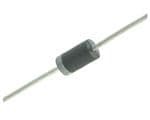
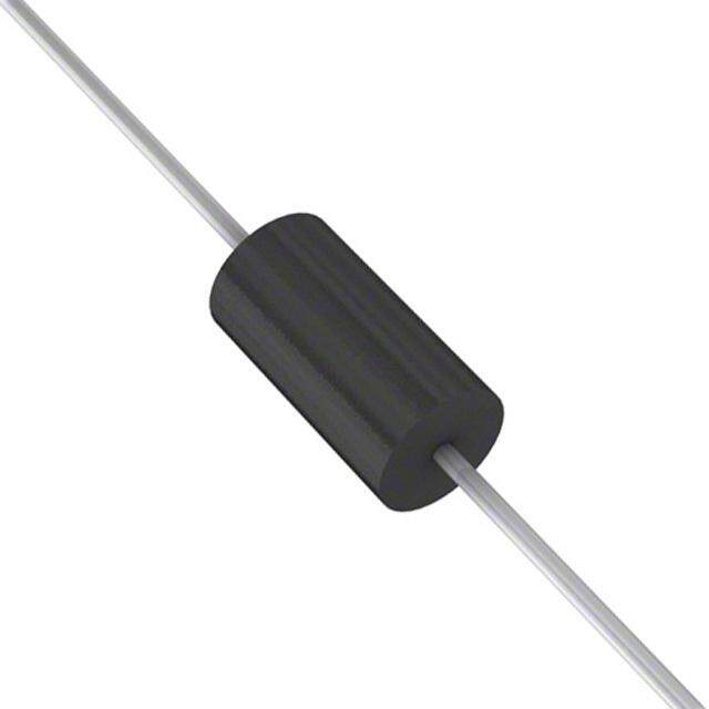
| 描述 | TVS DIODE 5VWM 9.2VC DO15TVS 二极管 - 瞬态电压抑制器 SA5.0CA Bi-Directional |
| 产品分类 | |
| 品牌 | Littelfuse |
| 产品手册 | |
| 产品图片 |
|
| rohs | 符合RoHS不受无铅要求限制 / 符合限制有害物质指令(RoHS)规范要求 |
| 产品系列 | 二极管与整流器,TVS二极管,TVS 二极管 - 瞬态电压抑制器,Littelfuse SA5.0CASA |
| 数据手册 | |
| 产品型号 | SA5.0CA |
| 不同频率时的电容 | - |
| 产品培训模块 | http://www.digikey.cn/PTM/IndividualPTM.page?site=cn&lang=zhs&ptm=22970 |
| 产品种类 | TVS 二极管 - 瞬态电压抑制器 |
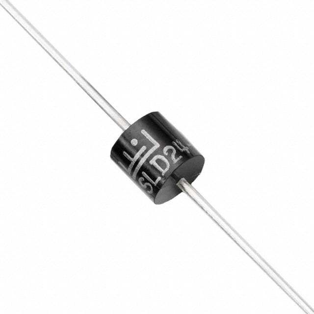
| 供应商器件封装 | DO-15 |
| 其它名称 | SA5.0CACCCT |
| 击穿电压 | 6.4 V |
| 功率-峰值脉冲 | 500W |
| 包装 | 剪切带 (CT) |
| 单向通道 | - |
| 双向通道 | 1 |
| 商标 | Littelfuse |
| 安装类型 | 通孔 |
| 安装风格 | Through Hole |
| 封装 | Reel |
| 封装/外壳 | DO-204AC,DO-15,轴向 |
| 封装/箱体 | DO-204AC |
| 尺寸 | 3.6 mm Dia. x 3.6 (Max) mm W x 7.6 mm L |
| 峰值浪涌电流 | 55.4 A |
| 峰值脉冲功率耗散 | 500 W |
| 工作温度 | -55°C ~ 150°C (TJ) |
| 工作电压 | 5 V |
| 工厂包装数量 | 4000 |
| 应用 | 通用 |
| 最大工作温度 | + 175 C |
| 最小工作温度 | - 55 C |
| 极性 | Bidirectional |
| 标准包装 | 1 |
| 电压-击穿(最小值) | 6.4V |
| 电压-反向关态(典型值) | 5V |
| 电压-箝位(最大值)@Ipp | 9.2V |
| 电流-峰值脉冲(10/1000µs) | 55.4A |
| 电源线路保护 | 无 |
| 端接类型 | Axial |
| 类型 | 齐纳 |
| 系列 | SA |
| 钳位电压 | 9.6 V |


- 商务部:美国ITC正式对集成电路等产品启动337调查
- 曝三星4nm工艺存在良率问题 高通将骁龙8 Gen1或转产台积电
- 太阳诱电将投资9.5亿元在常州建新厂生产MLCC 预计2023年完工
- 英特尔发布欧洲新工厂建设计划 深化IDM 2.0 战略
- 台积电先进制程称霸业界 有大客户加持明年业绩稳了
- 达到5530亿美元!SIA预计今年全球半导体销售额将创下新高
- 英特尔拟将自动驾驶子公司Mobileye上市 估值或超500亿美元
- 三星加码芯片和SET,合并消费电子和移动部门,撤换高东真等 CEO
- 三星电子宣布重大人事变动 还合并消费电子和移动部门
- 海关总署:前11个月进口集成电路产品价值2.52万亿元 增长14.8%


PDF Datasheet 数据手册内容提取
Transient Voltage Suppression Diodes Axial Leaded – 500W > SA series SA Series RoHS Pb e3 Description Bi-directional The SA Series is designed specifically to protect sensitive electronic equipment from voltage transients induced by lightning and other transient voltage events. Uni-directional Features • 500W peak pulse • EFT protection of data capability at 10/1000μs lines in accordance with waveform, repetition rate IEC 61000-4-4 (duty cycles):0.01% • Low incremental surge Agency Approvals • V @ T= V @25°C resistance BR J BR x (1+αT x (T - 25)) • Typical I less than 1μA AGENCY AGENCY FILE NUMBER (αT:TemperaJture when VR max>13V BR Coefficient, typical value E230531 • High temperature is 0.1%) to reflow soldering • Glass passivated chip guaranteed: 260°C/40sec Maximum Ratings and Thermal Characteristics junction in DO-15 Package / 0.375”,(9.5mm) lead (T =25OC unless otherwise noted) • Fast response time: length, 5 lbs., (2.3kg) A typically less than 1.0ps tension Parameter Symbol Value Unit from 0 Volts to BV min • Plastic package is Peak Pulse Power Dissipation by • Excellent clamping flammability rated V-0 per 10/1000μs Test Waveform (Fig.2) P 500 W capability Underwriters Laboratories PPM (Note 1) • Typical failure mode is • Matte tin lead–free plated Steady State Power Dissipation on P 3.0 W short from over-specified • Halogen free and RoHS Infinite Heat Sink at T=75ºC D L voltage or current compliant Peak Forward Surge Current, 8.3ms Single Half Sine Wave Unidirectional I 70 A • Whisker test is conducted • Pb-free E3 means 2nd Only (Note 2) FSM based on JEDEC level interconnect is Maximum Instantaneous Forward JESD201A per its table 4a Pb-free and the terminal Voltage at 35A for Unidirectional VF 3.5 V and 4c finish material is tin(Sn) Only • IEC-61000-4-2 ESD (IPC/JEDEC J-STD- Operating Junction and Storage T, T -65 to 175 °C 30kV(Air), 30kV (Contact) 609A.01) Temperature Range J STG • ESD protection of data Typical Thermal Resistance Junction R 20 °C/W lines in accordance with to Lead θJL IEC 61000-4-2 Typical Thermal Resistance Junction R 75 °C/W to Ambient θJA Applications Notes: TVS devices are ideal for the protection of I/O interfaces, 1. Non-repetitive current pulse , per Fig. 4 and derated above T (initial) =25OC per Fig. 3. J V bus and other vulnerable circuits used in telecom, 2. Measured on 8.3ms single half sine wave or equivalent square wave, duty cycle=4 per CC minute maximum. computer, industrial and consumer electronic applications. Functional Diagram Additional Infomarion Bi-directional Datasheet Resources Samples Cathode Anode Uni-directional © 2015 Littelfuse, Inc. Specifications are subject to change without notice. Revised: 11/20/15
Transient Voltage Suppression Diodes Axial Leaded – 500W > SA series Electrical Characteristics (T=25°C unless otherwise noted) A Nu(PUmanrbit) e r NuP(mBarib)t e r SRVtVeoavRnlt eda(Vrg so)eef f BreMakIdN(Voowltns )V @ol tMIaTgAeX VBR C(uTmerIrTsAe tn) t MCVVlaaoCxm(l@tiVmap )gIiuPnePmg PCMeuaarxrk(eAi mPn)utu lImsppe LMReaae@(xkvµia emAVgr)Rsueem I R AApgpernocvya l SA5.0A SA5.0CA 5.0 6.40 7.00 10 9.2 55.4 600 X SA6.0A SA6.0CA 6.0 6.67 7.37 10 10.3 49.5 600 X SA6.5A SA6.5CA 6.5 7.22 7.98 10 11.2 45.5 400 X SA7.0A SA7.0CA 7.0 7.78 8.60 10 12.0 42.5 150 X SA7.5A SA7.5CA 7.5 8.33 9.21 1 12.9 39.5 50 X SA8.0A SA8.0CA 8.0 8.89 9.83 1 13.6 37.5 25 X SA8.5A SA8.5CA 8.5 9.44 10.40 1 14.4 35.4 10 X SA9.0A SA9.0CA 9.0 10.00 11.10 1 15.4 33.1 5 X SA10A SA10CA 10.0 11.10 12.30 1 17.0 30.0 3 X SA11A SA11CA 11.0 12.20 13.50 1 18.2 28.0 1 X SA12A SA12CA 12.0 13.30 14.70 1 19.9 25.6 1 X SA13A SA13CA 13.0 14.40 15.90 1 21.5 23.7 1 X SA14A SA14CA 14.0 15.60 17.20 1 23.2 22.0 1 X SA15A SA15CA 15.0 16.70 18.50 1 24.4 20.9 1 X SA16A SA16CA 16.0 17.80 19.70 1 26.0 19.6 1 X SA17A SA17CA 17.0 18.90 20.90 1 27.6 18.5 1 X SA18A SA18CA 18.0 20.00 22.10 1 29.2 17.5 1 X SA20A SA20CA 20.0 22.20 24.50 1 32.4 15.7 1 X SA22A SA22CA 22.0 24.40 26.90 1 35.5 14.4 1 X SA24A SA24CA 24.0 26.70 29.50 1 38.9 13.1 1 X SA26A SA26CA 26.0 28.90 31.90 1 42.1 12.1 1 X SA28A SA28CA 28.0 31.10 34.40 1 45.4 11.2 1 X SA30A SA30CA 30.0 33.30 36.80 1 48.4 10.5 1 X SA33A SA33CA 33.0 36.70 40.60 1 53.3 9.6 1 X SA36A SA36CA 36.0 40.00 44.20 1 58.1 8.8 1 X SA40A SA40CA 40.0 44.40 49.10 1 64.5 7.9 1 X SA43A SA43CA 43.0 47.80 52.80 1 69.4 7.3 1 X SA45A SA45CA 45.0 50.00 55.30 1 72.7 7.0 1 X SA48A SA48CA 48.0 53.30 58.90 1 77.4 6.6 1 X SA51A SA51CA 51.0 56.70 62.70 1 82.4 6.2 1 X SA54A SA54CA 54.0 60.00 66.30 1 87.1 5.9 1 X SA58A SA58CA 58.0 64.40 71.20 1 93.6 5.4 1 X SA60A SA60CA 60.0 66.70 73.70 1 96.8 5.3 1 X SA64A SA64CA 64.0 71.10 78.60 1 103.0 5.0 1 X SA70A SA70CA 70.0 77.80 86.00 1 113.0 4.5 1 X SA75A SA75CA 75.0 83.30 92.10 1 121.0 4.2 1 X SA78A SA78CA 78.0 86.70 95.80 1 126.0 4.0 1 X SA85A SA85CA 85.0 94.40 104.00 1 137.0 3.7 1 X SA90A SA90CA 90.0 100.00 111.00 1 146.0 3.5 1 X SA100A SA100CA 100.0 111.00 123.00 1 162.0 3.1 1 X SA110A SA110CA 110.0 122.00 135.00 1 177.0 2.9 1 X SA120A SA120CA 120.0 133.00 147.00 1 193.0 2.6 1 X SA130A SA130CA 130.0 144.00 159.00 1 209.0 2.4 1 X SA150A SA150CA 150.0 167.00 185.00 1 243.0 2.1 1 X SA160A SA160CA 160.0 178.00 197.00 1 259.0 2.0 1 X SA170A SA170CA 170.0 189.00 209.00 1 275.0 1.9 1 X SA180A SA180CA 180.0 200.00 221.00 1 289.0 1.7 1 X For bidirectional type having V of 10 volts and less, the I limit is double. R R For parts without A , the V is ± 10% and Vc is 5% higher than with A parts. BR © 2015 Littelfuse, Inc. Specifications are subject to change without notice. Revised: 11/20/15
Transient Voltage Suppression Diodes Axial Leaded – 500W > SA series I-V Curve Characteristics Uni-directional Bi-directional Ipp IT Vc VBRVR IRVF V Vc VBRVR IR IIRT VRVBRVc V IT Ipp Ipp P Peak Pulse Power Dissipation -- Max power dissipation PPM V Stand-off Voltage -- Maximum voltage that can be applied to the TVS without operation R V Breakdown Voltage -- Maximum voltage that flows though the TVS at a specified test current (I) BR T V Clamping Voltage -- Peak voltage measured across the TVS at a specified Ippm (peak impulse current) C I Reverse Leakage Current -- Current measured at V R R V Forward Voltage Drop for Uni-directional F Ratings and Characteristic Curves (T=25°C unless otherwise noted) A Figure 1 - TVS Transients Clamping Waveform Figure 2 - Peak Pulse Power Rating Voltage Transients 100 TJ initial = Tamb W) K Voltage Across TVS er( w 10 ent Po or Curr Current Through TVS Pulse age eak 1 Volt -PM PPP 0.1 0.001 0.01 0.1 1 10 Td-Pulse Width(ms) Time continues on next page. © 2015 Littelfuse, Inc. Specifications are subject to change without notice. Revised: 11/20/15
Transient Voltage Suppression Diodes Axial Leaded – 500W > SA series Ratings and Characteristic Curves (T=25°C unless otherwise noted) (Continued) A Figure 3 - Peak Pulse Power Derating Curve Figure 4 - Pulse Waveform 150 Current (I)PPge %17050 ent, % IRSM 100 tr=1PI0PeµPasMke cValue TPacusuJ r=ltrsh2eee5n W °tpC diodeitnchta( wytdsh) teiosr e5d 0teh%fien opefde IaPkP M k Pulse Power (P) or PPDerating in Percenta 2550 I- Peak Pulse CurrPPM 50 HIPaPlMf Va(lI Pu P1a2e0sM /d1)0e0fi0nµesde bc.y W Ra.Ev.eAform a Pe 0 td 0 25 50 75 100 125 150 175 200 0 0 1.0 2.0 3.0 4.0 T - Initial Junction Temperature (ºC) J t-Time (ms) Figure 5 - Typical Junction Capacitance Figure 6 - Typical Transient Thermal Impedance 100 10000 W) Bi-directional V=0V °C/ e ( 1000 Uni-directional V=0V anc ed 10 p Cj (pF) 100 Uni-directioBni-adl i@re cVtRional @ VR Thermal Im ent 1 10 ansi Tj=25C Tr f=1.0MHz Vsig=50mVp-p 1 0.1 1.0 10.0 100.0 1000.0 0.01 0.1 1 10 100 1000 VBR - Reverse Breakdown Voltage (V) TP-Pulse Duration (s) Figure 7 - Maximum Non-Repetitive Forward Surge Figure 8 - Peak Forward Voltage Drop vs Peak Forward Current Uni-Directional Only Current (Typical Values) 100.0 120 A) nt(100 e ard Surve Curr 6800 ward Current(A) 10.0 ak Forw 40 Peak For 1.0 Pe I-F M - 20 FS I 0 1 10 100 0.1 Number of Cycles at 60 Hz 0.0 1.0 2.0 3.0 4.0 5.0 VF-Peak Forward Voltage(V) © 2015 Littelfuse, Inc. Specifications are subject to change without notice. Revised: 11/20/15
Transient Voltage Suppression Diodes Axial Leaded – 500W > SA series Soldering Parameters Lead–free Reflow Condition assembly TP tp - Temperature Min (T ) 150°C Ramp-up Critical Zone Pre Heat - Temperature Max (Tss(m(mina)x)) 200°C T) TL tL TL to TP Atov epreaagke ram- pT iumpe r a(mtei n(L tioq umidauxs) T(tes)mp (TA) 630°C –/ s1e8c0o nsde cmsax (Temperature TTss((mmainx)) Prethseat Ramp-down T to T - Ramp-up Rate 3°C/second max S(max) A 25˚C - Temperature (T ) (Liquidus) 217°C t 25˚C to Peak Reflow A Time (t) - Time (min to max) (t) 60 – 150 seconds s Peak Temperature (T) 260+0/-5 °C P Time within 5°C of actual peak Flow/Wave Soldering (Solder Dipping) 20 – 40 seconds Temperature (t) p Ramp-down Rate 6°C/second max Peak Temperature : 265OC Time 25°C to peak Temperature (T) 8 minutes Max. Dipping Time : 10 seconds P Do not exceed 260°C Soldering : 1 time Physical Specifications Environmental Specifications Weight 0.015oz., 0.4g High Temp. Storage JESD22-A103 JEDEC DO-204AC (DO-15) molded Case plastic body over passivated junction. HTRB JESD22-A108 Color band denotes the cathode except Polarity Temperature Cycling JESD22-A104 Bipolar. Matte Tin axial leads, solderable per H3TRB JESD22-A101 Terminal JESD22-B102. RSH JESD22-B106 Dimensions Inches Millimeters Cathode Band Dimensions Min Max Min Max (for Uni-directional products only) D A 1.000 - 25.40 - C B 0.230 0.300 5.80 7.60 C 0.028 0.034 0.71 0.86 A B A D 0.104 0.140 2.60 3.60 DO-204AC (DO-15) © 2015 Littelfuse, Inc. Specifications are subject to change without notice. Revised: 11/20/15
Transient Voltage Suppression Diodes Axial Leaded – 500W > SA series Part Numbering System Part Marking System SAxxxXXX OPTION CODE: BLANK Reel Tape Cathode Band -B Bulk Packaging F (for Uni-directional YYWW TYPE CODE: products only) A Uni-Directional (5% VBR Voltage Tolerance) Trace Code Marking CA Bi-Directional (5% VBR Voltage Tolerance) Littelfuse Logo YY:Year Code WW: Week Code VBR VOLTAGE CODE SAXXX (Refer to the Electrical Characteristics table) Product Type SERIES CODE Packaging Component Packaging Part Number Quantity Packaging Specification Package Option SAxxxXX DO-204AC 4000 Tape & Reel EIA STD RS-296 SAxxxXX-B DO-204AC 1000 Bulk Littelfuse Spec. Tape and Reel Specification Off Center (625.5.06) either side 2.0(5633.+00+.20.709//--10..00)39 0.028(0.7) 0.047 0.236 (1.2) (6.0) 0.197+/-0.020 (5.0+/- 0.5) Dimensions are in 13.0 inches/mm (330.2) 3.0 (76.2) 0.68 (17.27) 2.75 (69.85) Direction of Feed Recess Depth Max. 0.75 (19.05) © 2015 Littelfuse, Inc. Specifications are subject to change without notice. Revised: 11/20/15