 Datasheet下载
- 型号: P6KE16A
- 制造商: Fairchild Semiconductor
- 库位|库存: xxxx|xxxx
- 要求:
| 数量阶梯 | 香港交货 | 国内含税 |
| +xxxx | $xxxx | ¥xxxx |
查看当月历史价格
查看今年历史价格
P6KE16A产品简介:
ICGOO电子元器件商城为您提供P6KE16A由Fairchild Semiconductor设计生产,在icgoo商城现货销售,并且可以通过原厂、代理商等渠道进行代购。 P6KE16A价格参考。Fairchild SemiconductorP6KE16A封装/规格:TVS - 二极管, 。您可以下载P6KE16A参考资料、Datasheet数据手册功能说明书,资料中有P6KE16A 详细功能的应用电路图电压和使用方法及教程。
ON Semiconductor的P6KE16A是一款瞬态电压抑制(TVS)二极管,广泛应用于各种电子设备中,用于保护电路免受瞬态电压尖峰的损害。以下是该型号的具体应用场景:

 1. 电源线保护
   P6KE16A常用于电源线的保护,防止由于雷击、静电放电(ESD)、开关噪声等引起的瞬态电压对电源电路造成损坏。它能够在短时间内吸收大量能量,确保电源系统的稳定性和可靠性。

 2. 信号线保护
   在通信设备、工业控制系统和消费电子产品中,信号线容易受到外部电磁干扰(EMI)或瞬态电压的影响。P6KE16A可以有效地箝位这些瞬态电压,保护敏感的信号处理电路,确保数据传输的准确性和完整性。

 3. 汽车电子系统
   汽车环境中存在大量的电气噪声源,如发动机启动、继电器切换等,这些都可能产生瞬态电压尖峰。P6KE16A适用于汽车电子系统的电源输入、传感器接口、CAN总线等关键部位,提供可靠的过压保护,延长设备寿命。

 4. 消费电子产品
   在智能手机、平板电脑、笔记本电脑等消费电子产品中,P6KE16A可以用于USB端口、充电接口等易受外界干扰的部位,防止因不当操作或外部环境因素导致的电路损坏,提升产品的耐用性。

 5. 工业自动化设备
   工业环境中,电机启动、变频器运行等都会产生较大的瞬态电压。P6KE16A能够有效保护PLC控制器、传感器、执行器等关键组件,确保整个自动化系统的正常运行,减少因电压波动引起的故障停机。

 6. 医疗设备
   医疗设备对可靠性和安全性要求极高,任何瞬态电压都可能导致设备误操作甚至危及患者安全。P6KE16A可用于医疗仪器的电源输入、信号传输线路等,提供高效、稳定的过压保护,确保设备的安全性和准确性。

总之,P6KE16A凭借其快速响应、高耐压能力和低箝位电压特性,成为众多领域中不可或缺的保护元件,广泛应用于各类需要瞬态电压抑制的场合。
| 参数 | 数值 |
| 产品目录 | |
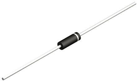
| 描述 | TVS DIODE 13.6VWM 22.5VC DO15TVS 二极管 - 瞬态电压抑制器 600 Watt TVS |
| 产品分类 | |
| 品牌 | Fairchild Semiconductor |
| 产品手册 | |
| 产品图片 |
|
| rohs | 符合RoHS无铅 / 符合限制有害物质指令(RoHS)规范要求 |
| 产品系列 | 二极管与整流器,TVS二极管,TVS 二极管 - 瞬态电压抑制器,Fairchild Semiconductor P6KE16A- |
| 数据手册 | |
| 产品型号 | P6KE16A |
| 不同频率时的电容 | - |
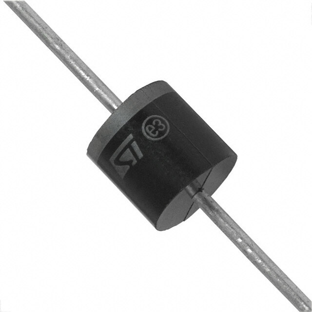
| 产品目录绘图 |
|
| 产品种类 | TVS 二极管 - 瞬态电压抑制器 |
| 供应商器件封装 | DO-15 |
| 其它名称 | P6KE16ACT |
| 击穿电压 | 15.2 V to 16.8 V |
| 功率-峰值脉冲 | 600W |
| 包装 | 剪切带 (CT) |
| 单位重量 | 300 mg |
| 单向通道 | 1 |
| 双向通道 | - |
| 商标 | Fairchild Semiconductor |
| 安装类型 | 通孔 |
| 安装风格 | Through Hole |
| 封装 | Reel |
| 封装/外壳 | DO-204AC,DO-15,轴向 |
| 封装/箱体 | DO-15 |
| 尺寸 | 3.56 (Max) mm W x 7.62 mm L |
| 峰值浪涌电流 | 27 A |
| 峰值脉冲功率耗散 | 600 W |
| 工作温度 | - |
| 工作电压 | 13.6 V |
| 工厂包装数量 | 4000 |
| 应用 | 通用 |
| 最大工作温度 | + 175 C |
| 最小工作温度 | - 65 C |
| 极性 | Unidirectional |
| 标准包装 | 1 |
| 电压-击穿(最小值) | 15.2V |
| 电压-反向关态(典型值) | 13.6V |
| 电压-箝位(最大值)@Ipp | 22.5V |
| 电容 | 1.6 pF |
| 电流-峰值脉冲(10/1000µs) | 27A |
| 电源线路保护 | 无 |
| 端接类型 | Axial |
| 类型 | 齐纳 |
| 系列 | P6KE16 |
| 钳位电压 | 22.5 V |


PDF Datasheet 数据手册内容提取
P6KE SERIES Taiwan Semiconductor CREAT BY ART 600W, 6.8V - 440V Transient Voltage Suppressor FEATURES - Excellent clamping capability - Low dynamic impedance - 600W surge capability at 10 / 1000 μs waveform - Fast response time: Typically less than 1.0ps from 0 volt to V for unidirectional BR and 5.0ns for bidirectional - Typical I less than 1μA above 10V R - UL recognized file # E-326243 - Compliant to RoHS Directive 2011/65/EU and in accordance to WEEE 2002/96/EC - Halogen-free according to IEC 61249-2-21 DO-204AC (DO-15) MECHANICAL DATA Case: DO-204AC (DO-15) Molding compound: UL flammability classification rating 94V-0 Part No. with suffix "H" means AEC-Q101 qualified Packing code with suffix "G" means green compound (halogen-free) Terminal: Pure tin plated leads, solderable per JESD22-B102 Meet JESD 201 class 2 whisker test Weight: 0.4g (approximately) MAXIMUM RATINGS AND ELECTRICAL CHARACTERISTICS (T =25°C unless otherwise noted) A PARAMETER SYMBOL VALUE UNIT Peak power dissipation at T =25°C, Tp=1ms (Note 1) P 600 W A PK Steady state power dissipation at T =75°C L P 5 W D lead lengths .375", 9.5mm (Note 2) Peak forward surge current, 8.3 ms single half sine-wave I 100 A superimposed on rated load (Note 3) FSM Operating junction temperature range T - 55 to +175 °C J Storage temperature range T - 55 to +175 °C STG Note 1: Non-repetitive current pulse per fig. 3 and derated above T =25°C per fig. 2 A Note 2: Mounted on 5 x 5 mm copper pads to each terminal Note 3: 8.3ms single half sine-wave or equivalent square wave, duty cycle=4 pulses per minute maximum Devices for Bipolar Applications 1. For bidirectional use C or CA suffix for types P6KE6.8 - types P6KE440 2. Electrical characteristics apply in both directions ORDERING INFORMATION PART NO. PACKING CODE PART NO. PACKING CODE PACKAGE PACKING SUFFIX SUFFIX A0 DO-15 1,500 / Ammo box P6KExxxx H R0 G DO-15 3,500 / 13" Paper reel (Note 1) B0 DO-15 1,000 / Bulk packing Note 1: "xxxx" defines voltage from 6.8V (P6KE6.8) to 440V (P6KE440) EXAMPLE EXAMPLE PART NO. PACKING CODE PART NO. PACKING CODE DESCRIPTION PART NO. SUFFIX SUFFIX AEC-Q101 qualified P6KE56AHA0G P6KE56A H A0 G Green compound Version: M1602
P6KE SERIES Taiwan Semiconductor CREAT BY ART RATINGS AND CHARACTERISTICS CURVES (T =25°C unless otherwise noted) A FIG. 1 PEAK PULSE POWER RATING CURVE FIG.2 PULSE DERATING CURVE 100 ) M 125 P R, KW Npshuoolnsw-ern ew pianev tfeiitgifvo.3erm RENT(IPE(%) 100 WE 10 URAG CT PO or EN 75 E ) PC S PR L PE U R(P AK P 1 OWEG IN 50 , PEM SE PATIN 25 PPP ULER PD 0.1 AK 0 E 0.1 1 10 100 1000 10000 P 0 25 50 75 100 125 150 175 200 tp, PULSE WIDTH, (μs) T , AMBIENT TEMPERATURE (°C) A FIG. 3 CLAMPING POWER PULSE WAVEFORM FIG. 4 MAXIMUM NON-REPETITIVE FORWARD SURGE CURRENT UNIDIRECTIONAL ONLY 140 Pulse width(td) is defined 100 tr=10μs as the point where the peak NT current decays to 50% of I E 8.3ms single half sine wave 120 PPM R %) Peak value UR NT ( 100 IPPM E C E Half value-IPPM/2 G R R UR 80 10/1000μs waveform SU C as defined by R.E.A. D E RA) S 60 A( L W U P R K 40 O A F E K P A 20 E P td M, 0 FS 10 0 0.5 1 1.5 2 2.5 3 3.5 4 I 1 10 100 t, TIME ms NUMBER OF CYCLES AT 60 Hz FIG. 5 TYPICAL JUNCTION CAPACITANCE 10000 A F) E (p VR=0 C N 1000 A T CI A P A C N 100 Measured at O stand-off TI voltage,Vwm C N f=1.0MHz U Vsig=50mVp-p J CJ, 10 1 10 100 V( ), BREAKDOWN VOLTAGE (V) BR Version: M1602
P6KE SERIES Taiwan Semiconductor CREAT BY ART Breakdown Voltage Test Stand-Off Maximum Maximum Maximum Maximum Nominal (Note 1) Current Voltage Reverse Leakage Peak Surge Clamping Voltage Temperature Voltage General @ V Current @ I Coefficient WM PPM Part V I V I I Vc of V Number BR T WM R PPM BR (V) (V) (mA) (V) (μA) (A) (V) (%/°C) Min Max (Note 2) P6KE6.8 6.8 6.12 7.48 10 5.50 1000 58.0 10.8 0.057 P6KE6.8A 6.8 6.46 7.14 10 5.80 1000 60.0 10.5 0.057 P6KE7.5 7.5 6.75 8.25 10 6.05 500 53.0 11.7 0.061 P6KE7.5A 7.5 7.13 7.88 10 6.40 500 55.0 11.3 0.061 P6KE8.2 8.2 7.38 9.02 10 6.63 200 50.0 12.5 0.065 P6KE8.2A 8.2 7.79 8.61 10 7.02 200 52.0 12.1 0.065 P6KE9.1 9.1 8.19 10.00 1 7.37 50 45.0 13.8 0.068 P6KE9.1A 9.1 8.65 9.55 1 7.78 50 47.0 13.4 0.068 P6KE10 10 9.00 11.00 1 8.10 10 42.0 15.0 0.073 P6KE10A 10 9.50 10.5 1 8.55 10 43.0 14.5 0.073 P6KE11 11 9.90 12.1 1 8.92 1 38.0 16.2 0.075 P6KE11A 11 10.5 11.6 1 9.40 1 40.0 15.6 0.075 P6KE12 12 10.8 13.2 1 9.72 1 36.0 17.3 0.078 P6KE12A 12 11.4 12.6 1 10.2 1 37.0 16.7 0.078 P6KE13 13 11.7 14.3 1 10.5 1 33.0 19.0 0.081 P6KE13A 13 12.4 13.7 1 11.1 1 34.0 18.2 0.081 P6KE15 15 13.5 16.5 1 12.1 1 28.0 22.0 0.084 P6KE15A 15 14.3 15.8 1 12.8 1 29.0 21.2 0.084 P6KE16 16 14.4 17.6 1 12.9 1 26.0 23.5 0.086 P6KE16A 16 15.2 16.8 1 13.6 1 28.0 22.5 0.086 P6KE18 18 16.2 19.8 1 14.5 1 23.0 26.5 0.088 P6KE18A 18 17.1 18.9 1 15.3 1 25.0 25.5 0.088 P6KE20 20 18.0 22.0 1 16.2 1 21.0 29.1 0.090 P6KE20A 20 19.0 21.0 1 17.1 1 22.0 27.7 0.090 P6KE22 22 19.8 24.2 1 17.8 1 19.0 31.9 0.092 P6KE22A 22 20.9 23.1 1 18.8 1 20.0 30.6 0.092 P6KE24 24 21.6 26.4 1 19.4 1 18.0 34.7 0.094 P6KE24A 24 22.8 25.2 1 20.5 1 19.0 33.2 0.094 P6KE27 27 24.3 29.7 1 21.8 1 16.0 39.1 0.096 P6KE27A 27 25.7 28.4 1 23.1 1 16.8 37.5 0.096 P6KE30 30 27.0 33.0 1 24.3 1 14.0 43.5 0.097 P6KE30A 30 28.5 31.5 1 25.6 1 15.0 41.4 0.097 P6KE33 33 29.7 36.3 1 26.8 1 13.0 47.7 0.098 P6KE33A 33 31.4 34.7 1 28.2 1 13.8 45.7 0.098 P6KE36 36 32.4 39.6 1 29.1 1 12.0 52.0 0.099 P6KE36A 36 34.2 37.8 1 30.8 1 12.6 49.9 0.099 P6KE39 39 35.1 42.9 1 31.6 1 11.1 56.4 0.100 P6KE39A 39 37.1 41.0 1 33.3 1 11.6 53.9 0.100 P6KE43 43 38.7 47.3 1 34.8 1 10.0 61.9 0.101 P6KE43A 43 40.9 45.2 1 36.8 1 10.6 59.3 0.101 P6KE47 47 42.3 51.7 1 38.1 1 9.2 67.8 0.101 P6KE47A 47 44.7 49.4 1 40.2 1 9.7 64.8 0.101 P6KE51 51 45.9 56.1 1 41.3 1 8.5 73.5 0.102 P6KE51A 51 48.5 53.6 1 43.6 1 8.9 70.1 0.102 P6KE56 56 50.4 61.6 1 45.4 1 7.8 80.5 0.103 P6KE56A 56 53.2 58.8 1 47.8 1 8.1 77.0 0.103 P6KE62 62 55.8 68.2 1 50.2 1 7.0 89.0 0.104 P6KE62A 62 58.9 65.1 1 53.0 1 7.4 85.0 0.104 Version: M1602
P6KE SERIES Taiwan Semiconductor CREAT BY ART Breakdown Voltage Test Stand-Off Maximum Maximum Maximum Maximum Nominal (Note 1) Current Voltage Reverse Leakage Peak Surge Clamping Voltage Temperature Voltage General @ V Current @ I Coefficient WM PPM Part V I V I I Vc of V Number BR T WM R PPM BR (V) (V) (mA) (V) (μA) (A) (V) (%/°C) Min Max (Note 2) P6KE68 68 61.2 74.8 1 55.1 1 6.4 98.0 0.104 P6KE68A 68 64.6 71.4 1 58.1 1 6.8 92.0 0.104 P6KE75 75 67.5 82.5 1 60.7 1 5.8 108 0.105 P6KE75A 75 71.3 78.8 1 64.1 1 6.1 103 0.105 P6KE82 82 73.8 90.2 1 66.4 1 5.3 118 0.105 P6KE82A 82 77.9 86.1 1 70.1 1 5.5 113 0.105 P6KE91 91 81.9 100 1 73.7 1 4.8 131 0.106 P6KE91A 91 86.5 95.5 1 77.8 1 5.0 125 0.106 P6KE100 100 90 110 1 81.0 1 4.3 144 0.106 P6KE100A 100 95 105 1 85.5 1 4.5 137 0.106 P6KE110 110 99 121 1 89.2 1 3.9 158 0.107 P6KE110A 110 105 116 1 94.0 1 4.1 152 0.107 P6KE120 120 108 132 1 97.2 1 3.6 173 0.107 P6KE120A 120 114 126 1 102 1 3.8 165 0.107 P6KE130 130 117 143 1 105 1 3.3 187 0.107 P6KE130A 130 124 137 1 111 1 3.5 179 0.107 P6KE150 150 135 165 1 121 1 2.9 215 0.108 P6KE150A 150 143 158 1 128 1 3.0 207 0.108 P6KE160 160 144 176 1 130 1 2.7 230 0.108 P6KE160A 160 152 168 1 136 1 2.8 219 0.108 P6KE170 170 153 187 1 138 1 2.5 244 0.108 P6KE170A 170 162 179 1 145 1 2.6 234 0.108 P6KE180 180 162 198 1 146 1 2.4 258 0.108 P6KE180A 180 171 189 1 154 1 2.5 246 0.108 P6KE200 200 180 220 1 162 1 2.1 287 0.108 P6KE200A 200 190 210 1 171 1 2.2 274 0.108 P6KE220 220 198 242 1 175 1 1.8 344 0.108 P6KE220A 220 209 231 1 185 1 1.9 328 0.108 P6KE250 250 225 275 1 202 1 1.7 360 0.110 P6KE250A 250 237 263 1 214 1 1.8 344 0.110 P6KE300 300 270 330 1 243 1 1.4 430 0.110 P6KE300A 300 285 315 1 256 1 1.5 414 0.110 P6KE350 350 315 385 1 284 1 1.2 504 0.110 P6KE350A 350 332 368 1 300 1 1.3 482 0.110 P6KE400 400 360 440 1 324 1 1.0 574 0.110 P6KE400A 400 380 420 1 342 1 1.1 548 0.110 P6KE440 440 396 484 1 356 1 1.0 631 0.110 P6KE440A 440 418 462 1 376 1 1.04 602 0.110 Notes: 1. V measure after I applied for 300μs, I =square wave pulse or equivalent. BR T T 2. Surge current waveform per figure. 3 and derate per figure. 2. 3. For bipolar types having V of 10 volts and under, the I limit is doubled. WM R 4. All terms and symbols are consistent with ANSI/IEEE C62.35. Version: M1602
P6KE SERIES Taiwan Semiconductor CREAT BY ART PACKAGE OUTLINE DIMENSIONS DO-204AC (DO-15) Unit (mm) Unit (inch) DIM. Min Max Min Max A 2.60 3.60 0.102 0.142 B 0.70 0.90 0.028 0.035 C 25.40 - 1.000 - D 5.80 7.60 0.228 0.299 E 25.40 - 1.000 - MARKING DIAGRAM P/N = Specific Device Code G = Green Compound YWW = Date Code F = Factory Code Note: Cathode band for uni-directional products only Version: M1602
P6KE SERIES Taiwan Semiconductor CREAT BY ART Notice Specifications of the products displayed herein are subject to change without notice. TSC or anyone on its behalf, assumes no responsibility or liability for any errors or inaccuracies. Information contained herein is intended to provide a product description only. No license, express or implied, to any intellectual property rights is granted by this document. Except as provided in TSC's terms and conditions of sale for such products, TSC assumes no liability whatsoever, and disclaims any express or implied warranty, relating to sale and/or use of TSC products including liability or warranties relating to fitness for a particular purpose, merchantability, or infringement of any patent, copyright, or other intellectual property right. The products shown herein are not designed for use in medical, life-saving, or life-sustaining applications. Customers using or selling these products for use in such applications do so at their own risk and agree to fully indemnify TSC for any damages resulting from such improper use or sale. Version: M1602