ICGOO在线商城 > 传感器,变送器 > 光学传感器 - 光断续器 - 槽型 - 晶体管输出 > PM-Y44
 Datasheet下载
- 型号: PM-Y44
- 制造商: Panasonic Corporation
- 库位|库存: xxxx|xxxx
- 要求:
| 数量阶梯 | 香港交货 | 国内含税 |
| +xxxx | $xxxx | ¥xxxx |
查看当月历史价格
查看今年历史价格
PM-Y44产品简介:
ICGOO电子元器件商城为您提供PM-Y44由Panasonic Corporation设计生产,在icgoo商城现货销售,并且可以通过原厂、代理商等渠道进行代购。 PM-Y44价格参考。Panasonic CorporationPM-Y44封装/规格:光学传感器 - 光断续器 - 槽型 - 晶体管输出, Optical Sensor Transmissive 0.197" (5mm) NPN - Dark-ON/Light-ON - Selectable Module, Wire Leads, Slot Type。您可以下载PM-Y44参考资料、Datasheet数据手册功能说明书,资料中有PM-Y44 详细功能的应用电路图电压和使用方法及教程。
Panasonic Industrial Automation Sales的光学传感器 - 光断续器 - 槽型 - 晶体管输出型号PM-Y44,主要应用于需要高精度检测和自动化控制的工业场景。以下是其典型应用场景:

 1. 计数与速度检测
   - PM-Y44可用于旋转编码器或传动带的速度测量。通过将目标物体(如齿轮、转轴)置于光断续器的槽中,传感器能够检测到物体的运动并生成脉冲信号,从而实现精确的速度和位置控制。
   - 应用实例:电机转速监控、生产线物品计数。

 2. 位置检测
   - 在自动化设备中,PM-Y44可以用来检测机械部件的位置。例如,在机器人手臂或输送带系统中,传感器可以判断某个部件是否到达指定位置。
   - 应用实例:包装机中的封口位置检测、印刷机的同步定位。

 3. 物料传输监控
   - 在物料传输过程中,PM-Y44可以安装在传送带两侧,用于检测物品是否存在或是否正确放置。晶体管输出设计使其能够快速响应,并与其他控制系统集成。
   - 应用实例:电子元件装配线上的零件到位检测、食品加工线的产品缺失检测。

 4. 编码与识别
   - 该型号适合用于条形码读取或其他编码识别任务。通过槽型设计,传感器可以准确捕捉经过的标记点或编码信息。
   - 应用实例:标签打印机的纸张进给检测、光学编码器的数据采集。

 5. 开关与触发功能
   - PM-Y44可以用作非接触式开关,当目标物进入传感器槽时触发信号输出。这种特性非常适合需要频繁操作且要求耐用性的场合。
   - 应用实例:电梯门关闭检测、自动门感应开关。

 6. 小型化设备中的嵌入式应用
   - 由于其紧凑的设计和高灵敏度,PM-Y44非常适合嵌入到小型化设备中,提供可靠的检测功能。
   - 应用实例:办公设备(如复印机、传真机)中的纸张路径检测、医疗设备中的流体流量监测。

 特性总结:
- 槽型设计:确保检测目标必须完全穿过光路,减少误判。
- 晶体管输出:支持高速响应和长距离信号传输。
- 高可靠性:适用于各种工业环境,包括振动、灰尘等恶劣条件。

综上所述,PM-Y44广泛应用于工业自动化、物流运输、电子产品制造等领域,为设备提供精准、稳定的检测解决方案。
| 参数 | 数值 |
| 产品目录 | |
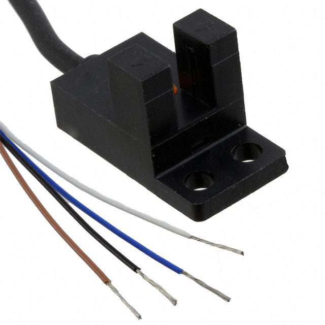
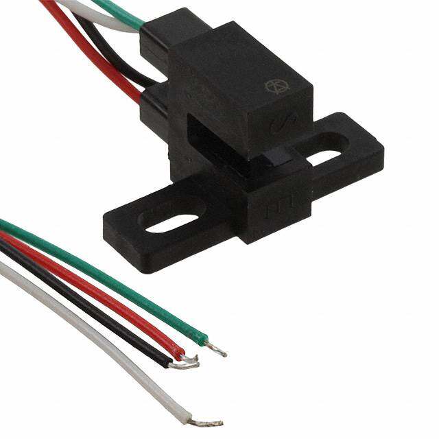
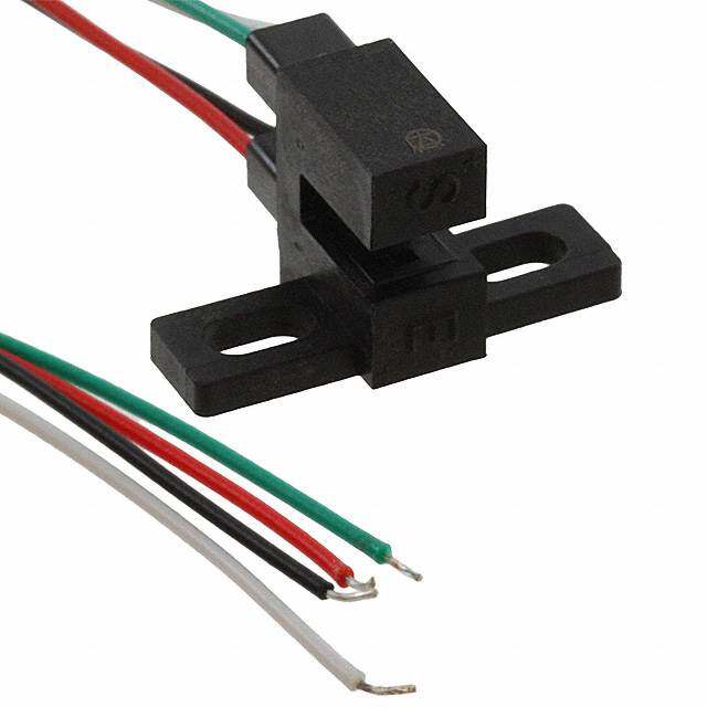
| 描述 | SENSOR 5MM 5-24VDC NPN CABLE1M |
| 产品分类 | |
| 品牌 | Panasonic Industrial Automation Sales |
| 数据手册 | |
| 产品图片 |
|
| 产品型号 | PM-Y44 |
| rohs | 无铅 / 符合限制有害物质指令(RoHS)规范要求 |
| 产品系列 | PM |
| 其它名称 | 1110-2019 |
| 包装 | 散装 |
| 响应时间 | 20µs |
| 安装类型 | 底座安装 |
| 封装/外壳 | 盒 |
| 工作温度 | -25°C ~ 55°C |
| 感应方法 | 可传导的 |
| 感应距离 | 0.197"(5mm) |
| 标准包装 | 1 |
| 特色产品 | http://www.digikey.cn/product-highlights/cn/zh/panasonic-acsd-pm-micro-photoelectric-sensors/3688 |
| 电压-集射极击穿(最大值) | - |
| 电流-DC正向(If) | - |
| 电流-集电极(Ic)(最大值) | - |
| 类型 | 无放大 |
| 输出配置 | NPN - 暗光/亮光 - 可选 |


- 商务部:美国ITC正式对集成电路等产品启动337调查
- 曝三星4nm工艺存在良率问题 高通将骁龙8 Gen1或转产台积电
- 太阳诱电将投资9.5亿元在常州建新厂生产MLCC 预计2023年完工
- 英特尔发布欧洲新工厂建设计划 深化IDM 2.0 战略
- 台积电先进制程称霸业界 有大客户加持明年业绩稳了
- 达到5530亿美元!SIA预计今年全球半导体销售额将创下新高
- 英特尔拟将自动驾驶子公司Mobileye上市 估值或超500亿美元
- 三星加码芯片和SET,合并消费电子和移动部门,撤换高东真等 CEO
- 三星电子宣布重大人事变动 还合并消费电子和移动部门
- 海关总署:前11个月进口集成电路产品价值2.52万亿元 增长14.8%
PDF Datasheet 数据手册内容提取
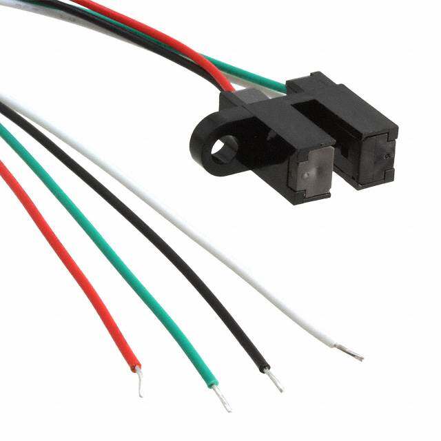
443 Small U-shaped Micro Photoelectric Sensor Amplifier Built-in PM-44 PM-54 SERIES SERIES ■ General terms and conditions ...........F-13 ■ Sensor selection guide ..................P.427~ FIBER Related Information SENSORS ■ Glossary of terms / General precautions ......P.1455~ / P.1458~ ■ Korea’s S-mark ..............................P.1506 LASER SENSORS PHOTOELECTRIC SENSORS Conforming to Recognition MICRO EMC Directive PHOTOELECTRIC SENSORS AREA Certified SENSORS (Some models only) LIGHT CURTAINS / SAFETY COMPONENTS PRESSURE / FLOW SENSORS INDUCTIVE PROXIMITY SENSORS PARTICULAR USE SENSORS SENSOR OPTIONS SIMPLE WIRE-SAVING UNITS WIRE-SAVING SYSTEMS MEASUSERNESMOERNST panasonic.net/id/pidsx/global PNP output type available STATIC ELECTRICITY PREVENTION DEVICES LASER MARKERS Enables space saving and quick installation! PLC HUMAN MACHINE INTERFACES Equipped with two independent outputs Quick fitting hook-up connector ENERGY CONSUMPTION VISUALIZATION All models are equipped with two independent outputs Easy to maintain connector COMPONENTS Light-ON and Dark-ON. type models are available. Its FA COMPONENTS Hence, one model suffices even if the output is to be exclusive connector is the hook- used differently, depending upon the location of use. up connector. MACHINE VISION Also, since two independent outputs have been Since only crimping with SYSTEMS provided, cumbersome handling of the output conversion exclusive pliers is to be done, Crimp the connector on the cable. UV CURING control input, or fear of logic inversion due to a cable cumbersome soldering or SYSTEMS break, is eliminated. The sensor can be connected to the insulation is absolutely not existing wiring as it is. required. Further, connector attached cable is also available. Example of connection with a commercial intermediate connector Commercial intermediate Selection connector Guide Quick connection to the U-shaped +V sensor. 0 V Convergent Reflective Output 1 (Light-ON) Output 2 (Dark-ON) To PLC APPLICATIONS PM-64 Just connect the cable of the used Connected device side Sensing the starting point and PM-24 output (either Light-ON or Dark-ON). can be left as it is. overrun of a moving body PM-44/PM-54 Note: Ensure to insulate the unused output wire. Overrun sensing Dog Wide model variety A wide variety of 12 shapes and 24 models is available. You may select from this wide range to suit the mounting Starting point sensing conditions. Starting point Meets global requirements and overrun is sensed using Overrun sensing the dog on the Conforms to Europe’s EMC Directive and obtains UL base. Recognition. The NPN output type with cable (excluding 3 m 9.843 ft cable length type) has also obtained Korea’s S- mark certification. Both, NPN and PNP output models are available.
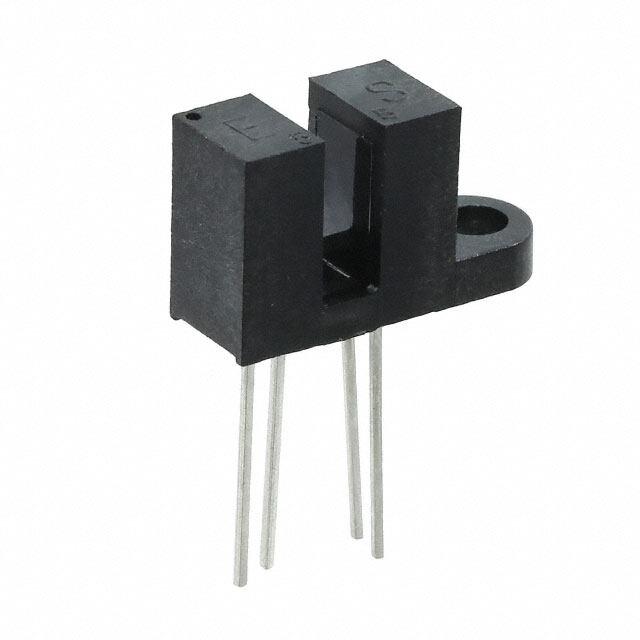
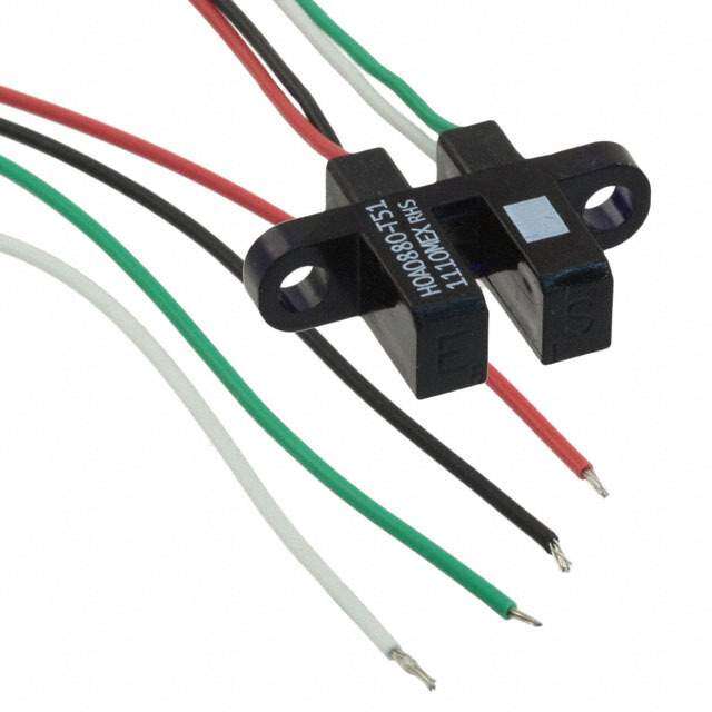
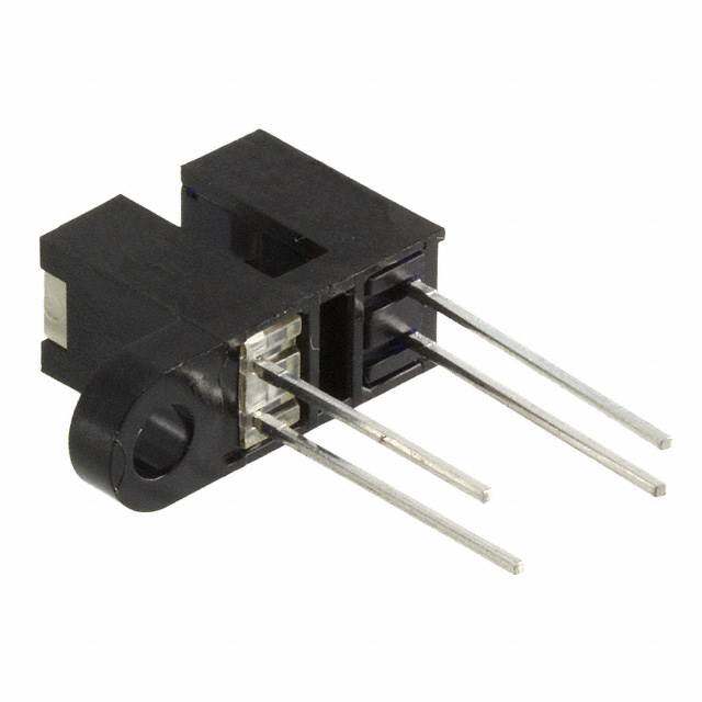
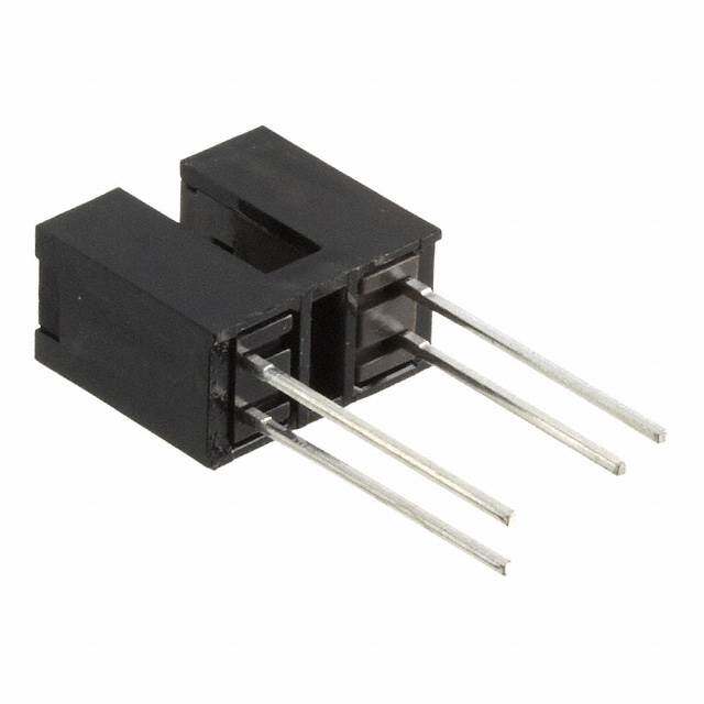
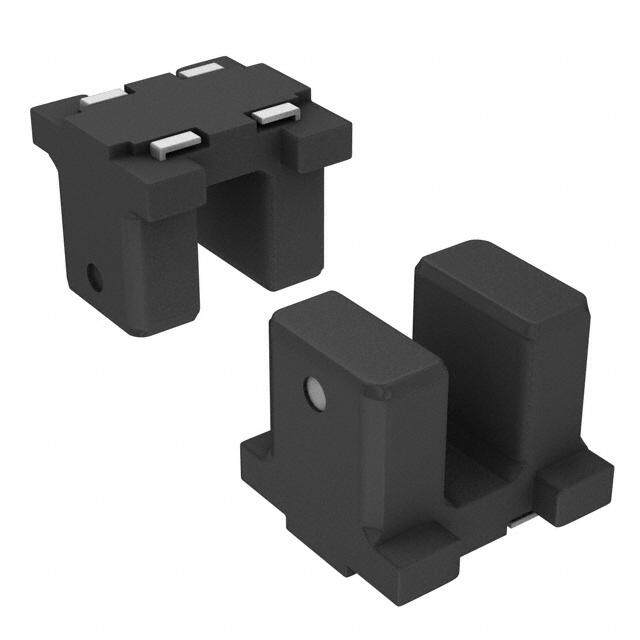
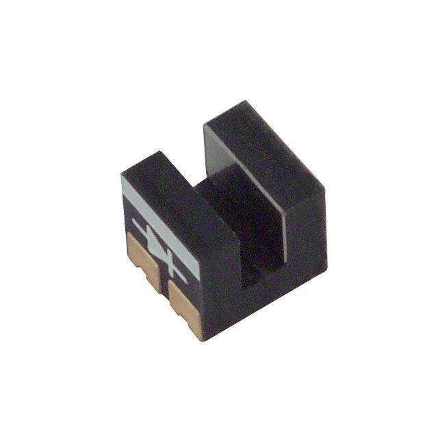
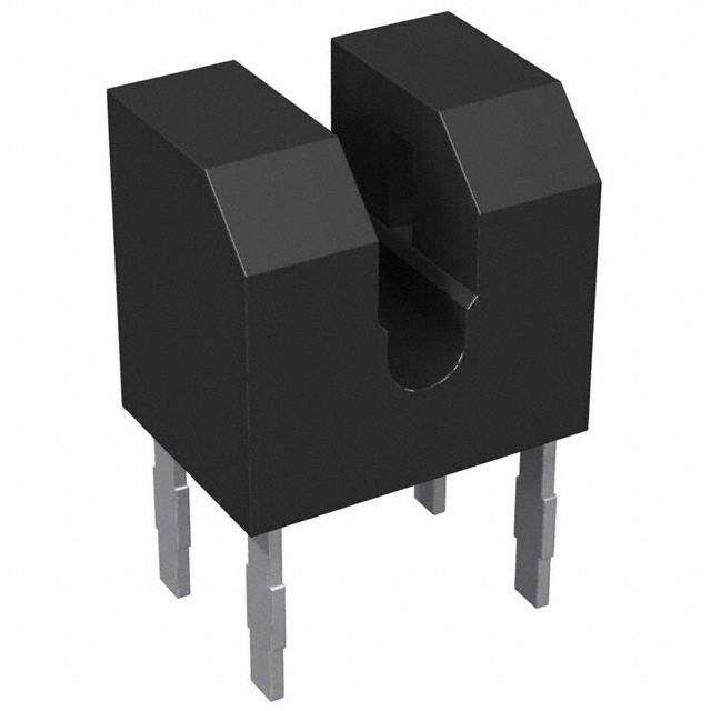
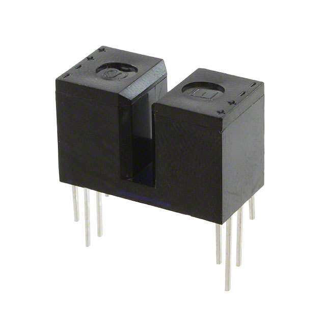
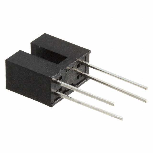
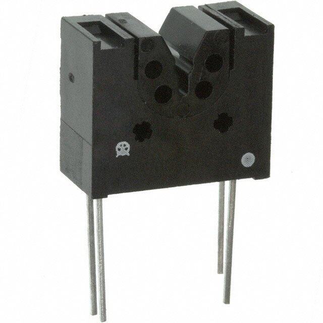
Small U-shaped Micro Photoelectric Sensor PM-44 SERIES PM-54 SERIES 444 ORDER GUIDE FIBER SENSORS LASER SENSORS Type Appearance (mm in) Sensing range Model No. Output Output operation PHOTO- ELECTRIC SENSORS MICRO 7 0.276 PM-K44 NPN open-collector transistor PHOTO- e ELECTRIC p SENSORS y K t AREA 25.4 26.2 PM-K44P PNP open-collector transistor SENSORS 1.000 1.031 LIGHT CURTAINS / SAFETY COMPONENTS 13.7 0.539 PM-T44 NPN open-collector transistor pe PFLROEWSSURE / y SENSORS T t 26 26.2 PM-T44P PNP open-collector transistor IPNRDOUXCIMTIIVTEY 1.024 1.031 SENSORS PARTICULAR USE PM-L44 NPN open-collector transistor SENSORS e p y 15.5 0.610 SENSOR L t OPTIONS able 12.062 4 01.87.258 PM-L44P PNP open-collector transistor SWIIMRPEL-SEAVING h c UNITS Wit 15.5 0.610 PM-Y44 NPN open-collector transistor WIRE-SAVING e SYSTEMS p y Y t 25.5 MMEEANSTURE- 13.4 1.004 PM-Y44P PNP open-collector transistor SENSORS 0.528 STATIC ELECTRICITY PREVENTION DEVICES PM-F44 NPN open-collector transistor e LASER yp 13.2 0.520 MARKERS F t 26.2 13.7 1.031 PM-F44P PNP open-collector transistor PLC 0.539 HUMAN 13.2 0.520 MACHINE PM-R44 NPN open-collector transistor INTERFACES pe ENERGY y CONSUMPTION R t 26.2 VCIOSMUPAOLINZAETNITOSN 13.7 1.031 PM-R44P PNP open-collector transistor mall 0.539 5 mm 0.197 in I2n coourtppourtsa:ted with FCAO MPONENTS S (fixed) Light-ON / Dark-ON MACHINE PM-K54 NPN open-collector transistor VISION pe 7 0.276 SYSTEMS y K t 12.50.040 02.28.724 PM-K54P PNP open-collector transistor UCSYVUS RTINEGM S 13.7 0.539 PM-T54 NPN open-collector transistor e p y T t 12.062 4 02.28.724 PM-T54P PNP open-collector transistor SGeuliedcetion U-shaped PM-L54 NPN open-collector transistor Convergent e Reflective p or L ty 15.5 0.610 nect 1.2062 4 01.45.751 PM-L54P PNP open-collector transistor PM-64 n o PM-24 c With e 15.5 0.610 PM-Y54 NPN open-collector transistor PPMM--4544/ p y Y t 21.5 13.4 0.846 PM-Y54P PNP open-collector transistor 0.528 PM-F54 NPN open-collector transistor e p y 13.2 0.520 F t 22.2 13.7 0.874 PM-F54P PNP open-collector transistor 0.539 13.2 0.520 PM-R54 NPN open-collector transistor e p y R t 22.2 13.7 0.874 PM-R54P PNP open-collector transistor 0.539
445 Small U-shaped Micro Photoelectric Sensor PM-44 SERIES PM-54 SERIES ORDER GUIDE FIBER SENSORS SENLSAOSERRS 3 m 9.843 ft cable length type PHOTO- 3 m 9.843 ft cable length type (standard: 1 m 3.281 ft) is also available. ESLEENCSTORRICS When ordering this type, suffix “-C3” to the model No. (e.g.) 3m 9.843 ft cable length type of PM-K44 is “PM-K44-C3”. MICRO PHOTO- ELECTRIC SENSORS AREA SENSORS LIGHT OPTIONS CURTAINS / SAFETY COMPONENTS PRESSURE / FLOW SENSORS Designation Model No. Description INDUCTIVE PROXIMITY SENSORS PARTICULAR Connector CN-14 Connector for soldering USE SENSORS SENSOR This connector can be hooked-up on 0.08 to 0.2 mm2 cable OPTIONS CN-14H simply in one grip. SIMPLE Wire diameter: ø0.7 to ø1.2 mm ø0.028 to ø0.047 in WIRE-SAVING Hook-up UNITS connector Suitable for UL standard cable. WIRESY-SSATVEINMGS CN-14H-2 This connector can be hooked-up on 0.18 to 0.22 mm2 cable simply in one grip. MEASURE- Wire diameter: ø1.2 to ø1.52 mm ø0.047 to ø0.060 in MENT SENSORS Length: STATIC ELECTRICITY 1 m 3.281 ft PREVDEENVTICIOENS CN-14H-C1 Net weight: 20 g approx. For the connector type, with 0.2 mm2 MARLAKSEERRS Catotancnheecdto crable 4-core cabtyre cable Length: Cable diameter: ø3.7 mm ø0.146 in 3 m 9.843 ft PLC CN-14H-C3 Net weight: 65 g approx. HUMAN MACHINE INTERFACES These are exclusive pliers for hook-up connectors CN-14H and Hook-up pliers CN-HP ENERGY CN-14H-2. CONSUMPTION VISUALIZATION COMPONENTS FA Connector Hook-up connector Connector attached cable Hook-up pliers COMPONENTS MACHINE • CN-14 • CN-14H • CN-14H-C1 • CN-HP VISION • CN-14H-2 • CN-14H-C3 SYSTEMS UV CURING SYSTEMS Selection Guide U-shaped Convergent Reflective PM-64 PM-24 PM-44/ PM-54
Small U-shaped Micro Photoelectric Sensor PM-44 SERIES PM-54 SERIES 446 SPECIFICATIONS FIBER SENSORS LASER Small SENSORS Type With cable With connector PEHLEOCTTOR-IC el No. NPN output PM-□44 PM-□54 SMPEHICNORSTOOOR-S Item Mod PNP output PM-□44P PM-□54P ESLEENCSTORRICS Sensing range 5 mm 0.197 in (fixed) AREA SENSORS Minimum sensing object 0.8 × 1.8 mm 0.031 × 0.071 in opaque object LIGHT CURTAINS / Hysteresis 0.05 mm 0.002 in or less SAFETY COMPONENTS Repeatability 0.03 mm 0.001 in or less PFLROEWSSURE / SENSORS Supply voltage 5 to 24 V DC ±10 % Ripple P-P 10 % or less INDUCTIVE PROXIMITY Current consumption 15 mA or less SENSORS PARTICULAR <NPN output type> <PNP output type> USE NPN open-collector transistor PNP open-collector transistor SENSORS • Maximum sink current: 50 mA • Maximum source current: 50 mA Output SENSOR • Applied voltage: 30 V DC or less (between output and 0 V) • Applied voltage: 30 V DC or less (between output and +V) OPTIONS • Residual voltage: 0.7 V or less (at 50 mA sink current) • Residual voltage: 0.7 V or less (at 50 mA source current) 0.4 V or less (at 16 mA sink current) 0.4 V or less (at 16 mA source current) SIMPLE WIRE-SAVING UNITS Utilization category DC-12 or DC-13 WIRE-SAVING SYSTEMS Output operation Incorporated with 2 outputs: Light-ON / Dark-ON MEASURE- Under light received condition: 20 µs or less, Under light interrupted condition: 100 µs or less MENT Response time SENSORS (Response frequency: 1 kHz or more) (Note 2) STATIC ELECTRICITY Operation indicator Vermilion LED (lights up under light received condition) PREVENTION DEVICES Pollution degree 3 (Industrial environment) LASER MARKERS Ambient temperature –25 to +55 °C –13 to +131 °F (No dew condensation or icing allowed), Storage: –30 to +80 °C –22 to +176 °F e c an Ambient humidity 35 to 85 % RH, Storage: 35 to 85 % RH PLC st esi Ambient illuminance Fluorescent light: 1,000 ℓx at the light-receiving face HUMAN onmental r EVMoltCage withstandability 1,000 V AC for one min. between all sEuNp p6l0y9 t4e7rm-5in-2als connected together and enclosure MIECVCNNIOOSATENMUCERSPAHRGUOLIFYIMNNZ APAEECTTN IIETOOSSNN nvir Insulation resistance 50 MΩ, or more, with 250 V DC megger between all supply terminals connected together and enclosure FA E COMPONENTS Vibration resistance 10 to 2,000 Hz frequency, 1.5 mm 0.059 in amplitude in X, Y and Z directions for two hours each MACHINE Shock resistance 15,000 m/s2 acceleration (1,500 G approx.) in X, Y and Z directions for three times each VISION SYSTEMS Emitting element Infrared LED (Peak emission wavelength: 940 nm 0.037 mil, non-modulated) UV CURING SYSTEMS Material Enclosure: PBT, Slit cover: Polycarbonate, Terminal part [PM-□54(P) only]: Solder plated Cable 0.09 mm2 4-core cabtyre cable, 1 m 3.281 ft long – Cable extension Extension up to total 100 m 328.084 ft is possible with 0.3 mm2, or more, cable. Weight Net weight: 15 g approx. Net weight: 3 g approx. Notes: 1) Where measurement conditions have not been specified precisely, the conditions used were an ambient temperature of +23 °C +73.4 °F. Selection 2) The response frequency is the value when the disc, given in the figure below, is rotated. Guide U-shaped Convergent Disc 1.8 mm 0.071 in Reflective Disc PM-64 PM-24 t = 0.2 mm 0.008 in PM-44/ 1.6 mm 0.063 in 1.6 mm 0.063 in PM-54
447 Small U-shaped Micro Photoelectric Sensor PM-44 SERIES PM-54 SERIES I/O CIRCUIT AND WIRING DIAGRAMS FIBER SENSORS LASER SENSORS PM-□44 PM-□54 NPN output type PHOTO- I/O circuit diagram Wiring diagram ELECTRIC SENSORS MICRO Color code for cable type (Note 2) Brown PHOTO- ELECTRIC SENSORS (Brown) +V Load SECNURSASTAORLAFIIGRENEHTSASYT / nsor circuit ZD2 TZr1D 1 (((WBNloahtcietke 1)) 5,OO30)uu mttppAuu tt m12 a(LNxo.oa tde 1,3) Load +– 5±1 t0o %24 V DC BWlahcitke Load +– 5±1 t0o %24 V DC PCROEMSPSONUERNET S/ Se Tr2 (Blue) 0 V 50 mA max. Blue FLOW SENSORS INDUCTIVE Internal circuit Users’ circuit Output operation PROXIMITY SENSORS Notes: 1) Make sure to connect terminals correctly as the sensor does not incorporate a reverse polarity protection circuit. Color code Output operation PARTICULAR USE Further, the output is not incorporated with a short-circuit SENSORS protection circuit. Do not connect it directly to a power supply or a Output 1 Black Light-ON capacitive load. Faulty wiring may result in damage. OSPETNISOONRS 2) The color code of the connector attached cable is also the same. Output 2 White Dark-ON 3) Ensure to insulate the unused output wire. SIMPLE WIRE-SAVING UNITS Symbols … ZD1, ZD2: Surge absorption zener diode WIRE-SAVING Tr1, Tr2 : NPN output transistor SYSTEMS MEASURE- MENT SENSORS PM-□44P PM-□54P PNP output type STATIC ELECTRICITY I/O circuit diagram Wiring diagram PREVENTION DEVICES Color code for cable type (Note 2) Brown LASER MARKERS (Brown) +V Black INTEMRAHFPCUAHMLCIANECNES ensor circuit Tr2 TZr1D 2 ZD1 ((WBhlitae)c Oku)tp uO5t 02u ( tNmpotueA t1 , 31m) (aN5x0o. tme A1 , 3m) aLxo.a d +– 5±1 t0o %24 V DC White Load Load +– 5±1 t0o %24 V DC CONSUEMNPETRIOGNY S (Blue) 0 V Load Blue VISUALIZATION COMPONENTS FA Internal circuit Users’ circuit Output operation COMPONENTS Notes: 1) Make sure to connect terminals correctly as the sensor does not MACHINE incorporate a reverse polarity protection circuit. Color code Output operation VISION Further, the output is not incorporated with a short-circuit SYSTEMS protection circuit. Do not connect it directly to a power supply or a Output 1 Black Light-ON UV capacitive load. Faulty wiring may result in damage. CURING Output 2 White Dark-ON SYSTEMS 2) The color code of the connector attached cable is also the same. 3) Ensure to insulate the unused output wire. Symbols … ZD1, ZD2: Surge absorption zener diode Tr1, Tr2 : PNP output transistor Selection Guide SENSING CHARACTERISTICS (TYPICAL) U-shaped Convergent Reflective PM-L44(P)/K44(P) PM-L54(P)/K54(P) Sensing position PM-64 PM-24 PM-44/ PM-54 Dark- Dark- ON ON 8.5 mm 7 mm 0.335 in 0.276 in ℓ ℓ 2.9 mm 0.114 in Beam Light- axis Light- ON0 1 2 3 4 ON0 1 2 3 4 0.039 0.079 0.118 0.157 0.039 0.079 0.118 0.157 Operating point ℓ (mm in) Operating point ℓ (mm in)
Small U-shaped Micro Photoelectric Sensor PM-44 SERIES PM-54 SERIES 448 PRECAUTIONS FOR PROPER USE Refer to p.1458~ for general precautions. FIBER SENSORS LASER All models SENSORS PHOTO- ELECTRIC Cable extension SENSORS • Never use this product as a sensing device MICRO for personnel protection. • Cable extension is possible up to an overall length of PEHLEOCTTOR-IC 100 m 328.084 ft with a 0.3 mm2, or more, cable. SENSORS • In case of using sensing devices for However, since a voltage drop shall occur due to the AREA personnel protection, use products which SENSORS cable extension, ensure that the power supply voltage meet laws and standards, such as OSHA, LIGHT ANSI or IEC etc., for personnel protection at the end of the cable attached to the sensor or at the CSAUFRETTAYINS / applicable in each region or country. sensor terminals is within the rating. COMPONENTS PRESSURE / FLOW SENSORS Total cable length 100 m 328.084 ft Make sure to connect terminals correctly as INDUCTIVE PROXIMITY the sensor does not incorporate a reverse Cable attached SENSORS polarity protection circuit. tnoe scetonrs toerr morin caolsn - +V Extension cable PUASRET ICULAR Further, the output is not incorporated with a Output + 5 to 24 V DC SENSORS short-circuit protection circuit. Do not connect 0 V – ±10 % SENSOR it directly to a power supply or a capacitive OPTIONS load. Faulty wiring may result in damage. SIMPLE Supply voltage: 4.5 V or more WIRE-SAVING UNITS But, when the overall cable length, including the cable Mounting attached to the sensor, is as given below, there is no WSYIRSET-ESMASVING need to confirm the voltage. • When fixing the sensor with screws, use M3 screws and MEASURE- MENT the tightening torque should not exceed the values given SENSORS below. Conductor cross-section area of STATIC Further, use small, round type plain washers (ø6 mm extension cable Total cable length EPLREECVTERNITCIIOTNY DEVICES ø0.236 in). 0.08 to 0.1 mm2 Up to 5 m 16.404 ft LASER MARKERS 0.2 mm2 Up to 10 m 32.808 ft M3 screws Model No. Tightening torque PLC 0.3 mm2 Up to 20 m 65.617 ft PM-□44(P) 0.5 N·m Spring washer HMUAMCHANIN E PM-□54(P) Others INTERFACES Plain washer ENERGY Outer diameter CONSUMPTION ø6 mm • Since the sensor is intended for VISUALIZATION ø0.236 in COMPONENTS use inside machines, no special FA countermeasures have been taken COMPONENTS against extraneous light. Take care MACHINE that extraneous light is not directly VISION SYSTEMS incident on the beam receiving section. UV • Do not use during the initial transient CURING SYSTEMS time (50 ms) after the power supply is switched on. Selection Guide U-shaped Convergent Reflective PM-64 PM-24 PM-44/ PM-54
449 Small U-shaped Micro Photoelectric Sensor PM-44 SERIES PM-54 SERIES PRECAUTIONS FOR PROPER USE FIBER Refer to p.1458~ for general precautions. SENSORS LASER SENSORS PM-□54 PM-□54P PHOTO- Cautions in plugging or unplugging a connector Crimping of hook-up connectors CN-14H and CN-14H-2 ELECTRIC SENSORS PMHIOCTROO- • Do not plug or unplug a connector more than Model No. ELECTRIC CN-14H CN-14H-2 SENSORS 10 times. Item AREA • Be sure not to give stress more than 5 N to SENSORS Conductor cross- 0.08 to 0.2 mm2 0.18 to 0.22 mm2 a terminal of both a connector and a sensor. section area (AWG28 to AWG24) (AWG25 to AWG24) CURTLAIIGNHST / If you do not follow the above cautions, it will COMPOSNAEFNETTSY cause a poor contact. Wire diameter ø0.7 to ø1.2 mm ø1.2 to ø1.52 mm ø0.028 to ø0.047 in ø0.047 to ø0.060 in PRESSURE / FLOW SENSORS Wire insulation Vinyl chloride or soft polyethylene Procedures of plugging or unplugging a connector material INDUCTIVE PROXIMITY SENSORS 1Insert a connector straight into a Hook PARTICUULASRE sensor until the connector lug is Lug Wire diameter SENSORS locked by the sensor hook. SENSOR OPTIONS SIMPLE Conductor cross-section area WIRE-SAVING UNITS WIRE-SAVING 2When unplugging, give as much 5 N or less Crimping method SYSTEMS stress as a connector lug can MEASURE- be relieved from a hook. Then 1Strip the cable sheath 15 mm 0.591 in, or more, and SENSMOERNST unplug it. insert the wires into the connector insertion holes till the STATIC wire tips reach the end. ELECTRICITY PREVENTION DEVICES Lead wire LASER MARKERS (Do not strip the wire insulation.) Caution: Be sure to hold a Cable sheath PLC connector when plugging 15 mm 0.591 in or more or unplugging it. Do HUMAN not hold a terminal or MACHINE INTERFACES a cable when plugging Arrangement of connector terminals CONSUEMNPETRIOGNY or unplugging the +V: +V VCISOUMAPLOIZNAETNIOTNS connector. +V 11 22 00VV 1: Output 1 (Light-ON) (Note) Power supply FA Otherwise, it will cause a 2: Output 2 (Dark-ON) COMPONENTS poor contact. 0V: 0 V MACHINE Note: Wire at Pin No.1 or 2 as per requirement. VISION SYSTEMS UV Soldering (Both connector CN-14 and sensor) 2Crimp with the exclusive hook-up pliers CN-HP. CURING SYSTEMS • If soldering is done directly on the terminals, strictly adhere to the conditions given below. Notes: 1) When attaching or Soldering temperature 260 °C 500 °F or less detaching the connector fitted with a cable, make Soldering time 3 sec. or less sure to hold the connector firmly before proceeding. Selection Soldering position Refer to the below figure 2) After crimping, do not pull Guide on the cable. U-shaped Sensor Connector Convergent Reflective 1.5 mm Caution: Make sure to use the exclusive hook-up 0.059 in +V 1 2 0V +V 1 2 0V pliers CN-HP. Commercially available PM-64 pliers cannot be used. Soldering PM-24 position PM-44/ PM-54 • Prior to using the sensor, affix the cable in a way as to avoid direct stress on the crimped part.
Small U-shaped Micro Photoelectric Sensor PM-44 SERIES PM-54 SERIES 450 DIMENSIONS (Unit: mm in) The CAD data in the dimensions can be downloaded from our website. FIBER SENSORS LASER PM-K44 PM-K44P Sensor PM-T44 PM-T44P Sensor SENSORS PHOTO- ELECTRIC 25.4 1.000 13.7 SENSORS 0.2776 19 0.748 3.5B 0e.a1m38 axis 0.539 73 00..211786 MPESHLEICENORCSTOTOORR-ICS 2-ø3.2 ø0.126 mounting holes AREA 19 0.748 Operation indicator 06.2.45 2 Beam axis SLIGEHNTSORS 13.4 0.528 (Vermilion) CURTAINS / 1 0.039 0.5197 2.9 0.114 06.2.542 SCAOFMEPTOYNENTS 13.4 0.528 PRESSURE / 8.5 0.335 Beam axis 1.2062 4 1 0.519 7 2.9 0.114 FSLEONWSORS 12.60.321 11 13.8 0.543 0.1463.39.2 80.5. 00.33395 Beam axis IPSNREDNOUSXCOIMTRIIVTSEY 0.43301.04.285 9.5 0.374 6.20 .126 0.1531 2 12.60.321 PUSAESRNET SIOCRUSLAR 0.244 2 0.1457 2m-oøu3n.8ti nøg0 .h1o5l0es 01.04.036 01.04.285 O(Vpeermraitliioonn )i ndicator SOEPNTSIOONRS 0.079 ø4.8 2.5 ø0.189 ø2.7 ø0.106 cable, 1 m 3.281 ft long 0.098 0.1794 8 2o-bmloonugn htionlge s 0.027 ø90 ø.148.89 ø1 2m.7 3 ø.208.110 f6t lcoanbgl e, SWUINIMRITPESL-SEAVING WIRE-SAVING SYSTEMS PM-L44 PM-L44P Sensor PM-Y44 PM-Y44P Sensor MEASURE- MENT SENSORS STATIC 26 1.024 7 ELECTRICITY 03.1.226 19 0.7481 0.039 4-R2 0.0319 0.276 2-ø3.5 ø0.138 mounting holes PDREEVVICEENSTION 7 Beam axis 3.5 0.138 LMAASREKRERS 0.276 18.5 7 0.276 0.72810.8 2-mounting oblong holes 25.5 Beam axis PLC 0.425 Operation indicator 1.004 15 (Vermilion) 10.8 0.591 HUMAN 0.425 MACHINE 0.0279 02.1.194ø0ø.148.89 1301..4035. 510.294.75828 ø2.7 ø0.106 cable, 1 m 3.281 ft long 06.2.452 0.0279ø0ø.148.8913.4 50.528 2ø.9O(2 V0.p7e.e1 rømr1a04it.lii1oo0nn6 )i ncdaibclaet,o 1r m 3.281 ft lo0n6.2g.542 IECVCFCNANIOOOST ENMMUERSPAPRGUOLOFYIMNZN APAEECTTNNIIETOOTSSNNS 8.5 0.335 Beam axis 3.3 0.197 01.56.1509 0.354 7.2 6.50.130 15.508.3.355 12.6Beam axis 02.0.598 MVSIYASSCIOTHENINM ES 0.283 0.256 0.610 0.496 6.5 03.1.642 0.17948 0.256 UCSYVUS RTINEGM S 2-ø3.2 ø0.126 mounting holes 3.3 0.130 PM-F44 PM-F44P Sensor PM-R44 PM-R44P Sensor Selection Beam axis Beam axis Guide U-shaped 0.029.58 7 7 20..50 98 CRoenflevectrigveent 0.276 13.7 13.7 0.276 0.539 13.2 13.2 0.539 0.520 0.520 PM-64 13.4 0.528 6.4 6.4 13.4 0.528 0.0319 0.519 7 20..911 4 9 0.2770 6.2 52 30..21 26 0.132.62 0.2502.27 7 6 02.1.194 0.519 7 10 .039 PPMM--4244/ Beam axis 8.5 0.354 8.5 Beam axis PM-54 0.335 9 0.335 0.354 12.60.321 01.35.365 0.277 6 0.277 6 01.35.365 12.60.321 01.04.285 4 0.157 3.3 0.130 3.3 0.1304 0.157 01.04.285 2 0.079 ø0ø.148.89 O(Vpeermraitliioonn )i ndicator 2-ø3.5 ø0.138 mounting holes 2m-oøu3n.5ti nøg0 .h1o3l8e s 0.027 9 ø4.8 ø2.7 ø0.106 cable, ø2.7 ø0.106 cable, 1 m 3.281 ft long ø0.189 1 m 3.281 ft long Operation indicator (Vermilion)
451 Small U-shaped Micro Photoelectric Sensor PM-44 SERIES PM-54 SERIES DIMENSIONS (Unit: mm in) FIBER The CAD data in the dimensions can be downloaded from our website. SENSORS LASER SENSORS PM-K54 PM-K54P Sensor PM-T54 PM-T54P Sensor PHOTO- ELECTRIC SENSORS 25.4 1.000 3.5 13.7 0.539 MICRO 19 0.748 0.138 7 0.276 PHOTO- 3 ESLEENCSTORRICS 0.2776 Beam axis 0.118 AREA SENSORS 2-ø3.2 ø0.126 mounting holes 6.4 Beam axis 0.252 LIGHT CURTAINS / 19 0.748 Operation indicator COMPOSNAEFNETTSY 13.54 0 0.1.95728 2(V.9e 0rm.1i1lio4n) 6.4 PRESSURE / 1 0.039 0.252 FLOW 13.4 0.528 INSDEUNCSTOIVRES 08.3.535 13.8Beam axis 1.20624 0.0319 0.5197 02.1.194 PSREONXSIMOIRTSY 02.28.72411 0.543 0.146.39 8.5 0.335 Beam axis PARSTEINCSUOULARSRES 5 0.1907.43306.2.868 5.5 0.217 6.203.1.226 0.15312 02.28.724 OSPETNISOONRS 2-ø3.8 ø0.150 mounting holes 0.244 06.2.348 06.2.868 O(Vpeermraitliioonn )indicator 5 0.197 WIRE-SSAIUMVNPIINTLGES 0.029.58 0.17948 2-mounting oblong holes WIRE-SAVING SYSTEMS PM-L54 PM-L54P Sensor PM-Y54 PM-Y54P Sensor MEASURE- MENT SENSORS STATIC 26 1.024 2-ø3.5 ø0.138 mounting holes ELECTRICITY 3.2 19 0.748 7 PREVDEENVTICIOENS 0.1261 0.039 4-R2 R0.079 1 0.276 0.039 LASER 7 Beam axis 3.5 0.138 MARKERS 14.5 0.276 PLC 0.57106.2.688 Ope2r-amtioounn intindgic aotbolrong holes 02.18.456 7 01.12 7B6e am axis (Vermilion) 6.8 0.433 0.268 HUMAN 13.4 MACHINE 5 0.528 5 0.197 Operation indicator INTERFACES 0.197 (Vermilion) ENERGY CONSUMPTION VISUALIZATION 2.9 13.4 0.528 13.4 COMPONENFTAS 0.114 0.5197 06.2.542 00.5.5192 78 02.1.194 06.2.542 COMPONENTS Beam axis 8.5 0.335 MAVCISHIIONNE 01.56.1509 0.354 7.2 6.5 15.5 08.3.355 12.6 Beam axis 0.20.958 SYSTEMS 0.283 0.256 0.610 0.496 6.5 0.256 UV 3.6 19 3.3 CURING 0.142 0.748 0.130 SYSTEMS 3.3 2-ø3.2 ø0.126 mounting holes 0.130 PM-F54 PM-F54P Sensor PM-R54 PM-R54P Sensor Selection Guide Beam axis Beam axis U-shaped Convergent 2.5 2.5 Reflective 0.098 7 7 0.098 0.276 0.276 13.7 13.7 0.539 0.539 PM-64 13.2 13.4 0.528 PPPMMM---425444/ 0.0319 01.035.519.2 478 02.1.194 00..527720 66.02 . 542 30..21 26 0.132.26 016.32..54022 . 27 07 .65 20 02.1.194 8 .5 0.519 7 B10e .0a3m9 axis Beam axis 8.5 9 0.335 0.335 9 0.354 22.2 22.2 0.354 7 13.6 0.874 0.874 13.6 7 0.276 0.535 6.8 6.8 0.535 0.276 3.3 0.130 0.268 0.268 3.3 0.130 5 0.197 5 0.197 2-ø3.5 ø0.138 mounting holes Operation indicator (Vermilion) Operation indicator (Vermilion) 2-ø3.5 ø0.138 mounting holes
Small U-shaped Micro Photoelectric Sensor PM-44 SERIES PM-54 SERIES 452 DIMENSIONS (Unit: mm in) The CAD data in the dimensions can be downloaded from our website. FIBER SENSORS LASER * Terminal part (PM-□54, PM-□54P) CN-14 Connector (Optional) SENSORS PHOTO- ELECTRIC SENSORS +V 1 2 0V MICRO PHOTO- 0.0139 0.0139 ESLEENCSTORRICS 13 4.6 ASRENEASORS 0.512 0.181 0.015.31 00..8031 t 0.3 1 LCIUGRHTTAINS / 2.1 1.6 t 0.012 7.5 0.039 SAFETY 0.083 0.063 0.295 +V 1 2 0V 1 1 0V 2 1 +V COMPONENTS 20..15040 20..15040 20..15040 (0.(159) 7) 0.039 0.039 PFSLREONEWSSSOURRSE / t 0.4 t 0.016 0.8 0.031 IPNRDOUXCIMTIIVTEY 2 0.079 SENSORS 6 1.6 0.063 0.236 (2.54) (0.100) PARTICULAR USE (7.62) SENSORS (0.300) SENSOR OPTIONS CN-14H CN-14H-2 Hook-up connector (Optional) CN-14H-C1 CN-14H-C3 Connector attached cable (Optional) SWIIMRPEL-SEAVING UNITS L WIRE-SAVING SYSTEMS 15 (50) 0.591 (1.969) MEASURE- (8) MENT (0.315) SENSORS 13 0.1531 2 +1 2 0V V SEPTLREAECTVITECRN ITCIIOTNY 0.512 DEVICES 6 LASER 0.236 MARKERS 15 +V 1 2 0V 0.591 PLC 0V 2 1 +V ø3.7 ø0.146 cable HUMAN 0.263 6 • Length L MINATCEHRIFNAEC ES ENERGY Model No. Length L CONSUMPTION VISUALIZATION COMPONENTS CN-14H-C1 1 m 3.281 ft +V 1 2 0V FCAO MPONENTS CN-14H-C3 3 m 9.843 ft MACHINE VISION SYSTEMS UV CURING SYSTEMS Selection Guide U-shaped Convergent Reflective PM-64 PM-24 PM-44/ PM-54