 Datasheet下载
- 型号: PEC12R-4220F-N0024
- 制造商: Bourns
- 库位|库存: xxxx|xxxx
- 要求:
| 数量阶梯 | 香港交货 | 国内含税 |
| +xxxx | $xxxx | ¥xxxx |
查看当月历史价格
查看今年历史价格
PEC12R-4220F-N0024产品简介:
ICGOO电子元器件商城为您提供PEC12R-4220F-N0024由Bourns设计生产,在icgoo商城现货销售,并且可以通过原厂、代理商等渠道进行代购。 PEC12R-4220F-N0024价格参考。BournsPEC12R-4220F-N0024封装/规格:编码器, 。您可以下载PEC12R-4220F-N0024参考资料、Datasheet数据手册功能说明书,资料中有PEC12R-4220F-N0024 详细功能的应用电路图电压和使用方法及教程。
Bourns Inc. 的 PEC12R-4220F-N0024 是一款旋转编码器,广泛应用于需要精确角度检测和位置控制的场景。以下是其主要应用场景:

 1. 工业自动化设备
   - 用于机器人关节、机械臂或传送带的速度和位置控制。
   - 在 CNC 机床中,用于监控主轴或进给系统的旋转角度和速度。

 2. 消费电子产品
   - 应用于多媒体设备(如音响、电视)的音量调节旋钮或菜单导航旋钮。
   - 在家用电器(如洗衣机、空调)中,用于控制面板上的功能选择和参数调节。

 3. 医疗设备
   - 在医疗仪器中(如呼吸机、输液泵),用于精确控制电机的转速和位置。
   - 用于手术机器人或诊断设备中的角度反馈系统。

 4. 汽车电子
   - 用于车载信息娱乐系统的旋钮操作,例如调节音量或浏览菜单。
   - 在电动车窗、座椅调节等系统中,用于检测电机的旋转状态。

 5. 安防与监控设备
   - 在摄像头云台中,用于控制水平和垂直旋转的角度。
   - 用于门禁系统中的位置检测和角度调整。

 6. 航空航天与军事
   - 在飞行器控制系统中,用于监测舵面或天线的旋转角度。
   - 在军事设备中,用于精密仪器的位置反馈。

 7. 实验室与测试设备
   - 在实验仪器中,用于调节参数或记录旋转角度。
   - 在测试平台中,用于监控电机或旋转部件的性能。

PEC12R-4220F-N0024 编码器具有高分辨率(24 格/圈)、耐用性和紧凑设计,适合各种恶劣环境下的应用。其 IP60 防护等级和长寿命特性使其成为需要可靠性和稳定性的理想选择。
| 参数 | 数值 |
| 产品目录 | |
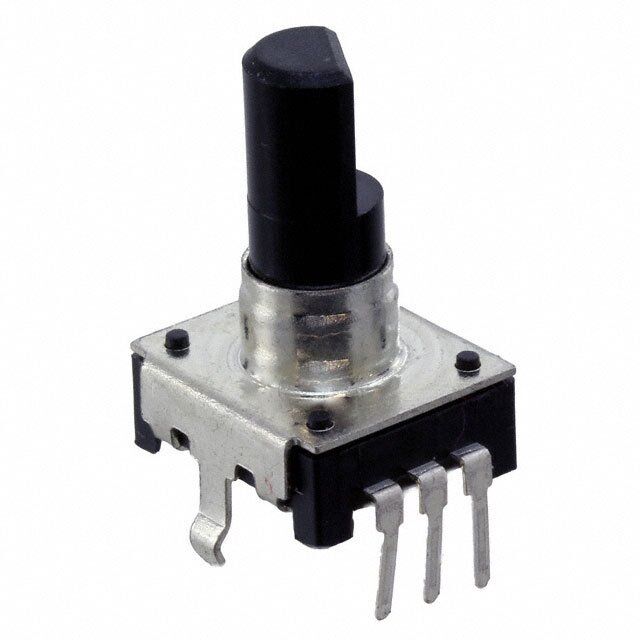
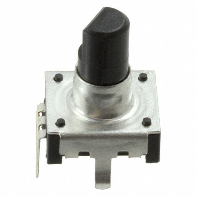
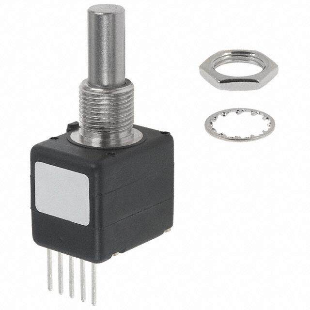
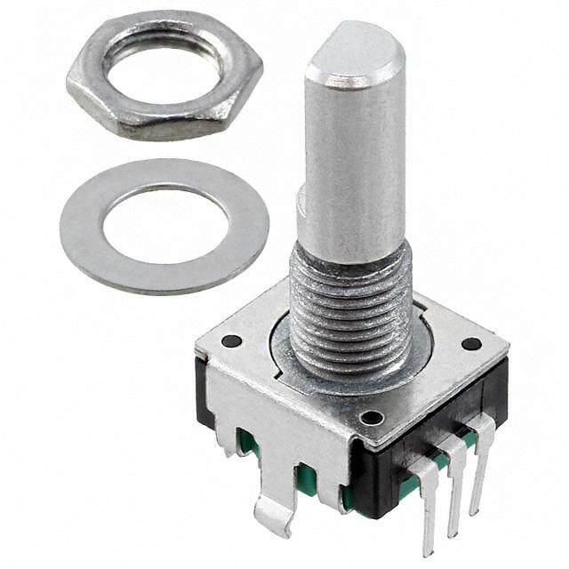
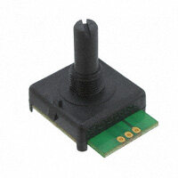
| 描述 | ENCODER ROTARY编码器 20mm NO SWITCH |
| 产品分类 | |
| 品牌 | Bourns Inc. |
| 产品手册 | |
| 产品图片 |
|
| rohs | 符合RoHS无铅 / 符合限制有害物质指令(RoHS)规范要求 |
| 产品系列 | Bourns PEC12R-4220F-N0024PEC12R |
| mouser_ship_limit | 该产品可能需要其他文件才能进口到中国。 |
| 数据手册 | |
| 产品型号 | PEC12R-4220F-N0024 |
| PCN封装 | |
| 产品 | Mechanical Encoders |
| 产品种类 | |
| 内置开关 | 无 |
| 分辨率 | 24 PPR |
| 制动器数量 | 24 Detent |
| 商标 | Bourns |
| 大小/尺寸 | 12 mm |
| 套管材料 | - |
| 套管螺纹 | - |
| 安装类型 | PCB,通孔 |
| 安装风格 | Snap In |
| 封装 | Bulk |
| 工作温度范围 | - 30 C to + 70 C |
| 工厂包装数量 | 100 |
| 带开关 | No Switch |
| 技术 | Rotary |
| 旋转寿命(最少次数) | 30K |
| 朝向 | 垂直 |
| 标准包装 | 100 |
| 棘爪 | 是 |
| 每转脉冲数 | 24 |
| 电压-电源 | - |
| 电源电压 | - |
| 端子类型 | PC 引脚 |
| 端接类型 | Through Hole |
| 类型 | Incremental |
| 系列 | PEC12R |
| 编码器类型 | 机械 |
| 致动器类型 | 6mm 直径扁平端 |
| 衬套大小 | - |
| 轴直径 | 6 mm |
| 轴类型 | Flatted |
| 轴长度 | 20 mm |
| 输出 | Quadrature |
| 输出类型 | 正交(增量) |
| 通道数量 | 2 Channel |


- 商务部:美国ITC正式对集成电路等产品启动337调查
- 曝三星4nm工艺存在良率问题 高通将骁龙8 Gen1或转产台积电
- 太阳诱电将投资9.5亿元在常州建新厂生产MLCC 预计2023年完工
- 英特尔发布欧洲新工厂建设计划 深化IDM 2.0 战略
- 台积电先进制程称霸业界 有大客户加持明年业绩稳了
- 达到5530亿美元!SIA预计今年全球半导体销售额将创下新高
- 英特尔拟将自动驾驶子公司Mobileye上市 估值或超500亿美元
- 三星加码芯片和SET,合并消费电子和移动部门,撤换高东真等 CEO
- 三星电子宣布重大人事变动 还合并消费电子和移动部门
- 海关总署:前11个月进口集成电路产品价值2.52万亿元 增长14.8%
PDF Datasheet 数据手册内容提取
NT *RoHS VCEOARVMSIAPILOLINAASBLE Features NT MPLIA n Compact design, long life and high HS CO reliability *Ro n Momentary push switch option n Available in a wide variety of configurations to meet many user requirements REE D F LEA PEC12R - 12 mm Incremental Encoder Electrical Characteristics OCID noiuseSntulpeetlaaucacttt i .rLto.i c.eRn. .v W.aR.e.t.ielin t..h..sg..is..s ...t...ta...a...n...n...d...c...i...en...... g........ ....V........o........l....t....a........g........e....................................................................................................L....VE....E....AR....DH.... SI....SF ....ORC....NE....O....SE ....M....AP....RL....IE.... A........N....T....*...................................................................................................................................................................................................................................................................................................................................................................................................................................................1......0...... ...m.....2..e..-..gb....oi.t5 h1q0m0u V asmA d@ArCa @t2mu5r ien05 i mcVVoDDudmCCe Electrical Travel .................................................R.o...................................................................................................................................................Continuous Contact Bounce (15 RPM)........................................................................................................................................................................2.0 ms. maximum** RPM (Operating) ............................................................................................................................................................................................100 maximum** Environmental Characteristics Operating Temperature Range .......................................................................................................................................-30 °C to +70 °C (-22 °F to +158 °F) Storage Temperature Range ..........................................................................................................................................-40 °C to +85 °C (-40 °F to +185 °F) Humidity.................................................................................................................................................................MIL-STD-202, Method 103B, Condition B Vibration ................................................................................................................................................................10~55~10 Hz / 1 min. / Amplitude 1.5 mm Shock.............................................................................................................................................................................................................................100 G Rotational Life....................................................................................................................................................................................30,000 cycles minimum Switch Life .........................................................................................................................................................................................20,000 cycles minimum IP Rating ..........................................................................................................................................................................................................................IP 40 Mechanical Characteristics Mechanical Angle .........................................................................................................................................................................................360 ° continuous Torque Detent ............................................................................................................................................................................30 to 90 gf-cm (0.41 to 1.25 oz-in) Running .........................................................................................................................................................................10 to 70 gf-cm (0.14 to 0.97 oz-in) Mounting .......................................................................................................................................................................10.2 kgf.cm (8.83 lb.-in.) maximum Shaft Side Load (Static)................................................................................................................................................................2.04 kgf (4.5 lbs.) minimum Weight ..............................................................................................................................................................................................3 gm (0.1 oz.) maximum Terminals .................................................................................................................................................................................Printed circuit board terminals Terminals .................................................................................................................................................................................Printed circuit board terminals Soldering Condition Wave Soldering ..........................................................................................Sn95.5/Ag2.8/Cu0.7 solder with no-clean flux: 260 °C max. for 3 ± 1 sec. Hand Soldering .................................................................................................................................................................................Not recommended Hardware ..................................................................................................One flat washer and one mounting nut supplied with each encoder with bushing Switch Characteristics Switch Type ....................................................................................................................................................................Contact Push ON Momentary SPST Power Rating (Resistive Load) .....................................................................................................................................................................10 mA at 5 V DC Switch Travel ......................................................................................................................................................................................................0.5 ± 0.3 mm Switch Actuation Force ........................................................................................................................................................610 ± 306 gf (8.47 ± 4.24 oz.-in.) Contact Resistance ...........................................................................................................................................................................100 milliohms @ 5 VDC How To Order Quadrature Output Table PEC12R - 4 0 20 F - S 0012 Model CW Terminal/Bushing Configuration 2 = Vertical Mount - Radial PC Pin/No Bushing OFF 3 = Horizontal Mount - Axial PC Pin/with Bushing A Signal ON 4 = Horizontal Mount - Axial PC Pin/No Bushing Detent Option 0 = No Detents B Signal 1 = 12 Detents (available with 12 pulses only) 2 = 24 Detents D Standard Shaft Length CCW 15 = 15.0 mm (Horizontal Mount/No Bushing only) 22 = 22.5 mm 17 = 17.5 mm 25 = 25.0 mm 20 = 20.0 mm 30 = 30.0 mm Shaft Style *RoHS Directive 2002/95/EC Jan. 27, 2003 including F = Insulated Flatted Shaft annex and RoHS Recast 2011/65/EU June 8, 2011. Switch Configuration **Devices are tested using standard noise reduction S = Push Momentary Switch filters. For optimum performance, designers should N = No Switch use noise reduction filters in their circuits. Resolution 0012 = 12 Pulses per 360 ° Rotation Specifications are subject to change without notice. 0024 = 24 Pulses per 360 ° Rotation Users should verify actual device performance in their specific applications. The products described herein and this document are subject to specific legal disclaimers as set forth on the last page of this document, and at www.bourns.com/ WARNING Cancer and Reproductive Harm - www.P65Warnings.ca.gov docs/legal/disclaimer.pdf.
Applications Level control, tuning and timer settings in: n Audio-visual equipment n Consumer electric appliances n Musical instrumentation n Communications equipment 3P3EC1212 -R 2 - m12m m SmM IDn cTrreimmemnitanlg E Pnoctoednetriometer Product Dimensions PEC12R-2xxxF-Nxxxx (Vertical Mount - Radial PC Pin/No Bushing, No Switch) L 5.0 5.0 12.5 (.197) (.197) (.492) 0.5 DIA.(.72.706) C(.020) 2.0 +0.2/-0 10.8 10.0 (.079 +.008/-0) (.425) 2.5 (.394) 2 PLCS. (.098) 13.4 (.528) A C B F 2.1 +0.2/-0 3.5 (.083 +.008/-0) 1.0 +0.1/-0 (.138) 4.5 +0/-0.1 2 PLCS. 5.0 (.039 +.004/-0) (.177 +0/-.004) A C B ACHANNEL A (.197) DIA. 3 PLCS. 0.8 CCOMMON (.031) DIA. 6.0 BCHANNEL B (.236) 0.8 MOUNTING (.032) 1.9 SURFACE 5.0 (.075) 2.5 (.197) 10.2 (.098) 4.1 (.402) 2.4 (.160) (.094) PEC12R-2xxxF-Sxxxx (Vertical Mount - Radial PC Pin/No Bushing, Push Momentary Switch) L 6.0 5.0 12.5 (.236) (.197) (.492) 0.5 0.5 (1.30D9.I04A).(.72.706) ST(.RW0AI2TV0CE)HL C(.020) (.027.209 P++0.L0.C20S/8-./0-0) (1.402.85) (.20.958) (.31.358) 5 VDC 13.4 1 2 (.528) A C B 2.1 +0.2/-0 10K OHMS 10K OHMS F (.083 +.008/-0) 10K OHMS 10K OHMS 2 PLCS. 1.0 +0.1/-0 0.8 (.147.57 ++00//--0.0.104) TERMINAL A A C B ACCCHOAMNMNOENLT AERMINAL B (.51.907) (.D0I3A9. +5. 0P0L4C/S-0.) (.031) DIA. 6.0 0.01 μF BCHANNEL B0.01 μF (.236) 3.5 0.8 (.138) MOUNTING (.032) ENCODER SURFACE 5.0 1.9 3.5 (.197) TERMINAL C 10.2 (.075) (.138) 5.1 (.402) 2.4 (.201) (.094) Switch Circuit Suggested Filter Circuit L 17.5 20.0 22.5 25.0 30.0 5 VDC (.688) (.787) (.886) (.984) (1.181) 5.0 7.0 7.0 12.0 12.0 1 2 10K OHMS 10K OHMS F (.197) (.276) (.276) (.472) (.472) 10K OHMS 10K OHMS TERMINAL A TERMINAL B MM DIMENSIONS: (INCHES) CW 0.01 μF 0.01 μF TOLERANCE: < 1 0 = ±0.3 ENCODER (<.400) (±.012) OFF ≥ 1 0 = ±0.5 A Signal ON TERMINAL C (≥.400) (±.020) B Signal D Specifications are subject to change without notice. Users should verify actual device performance in their specific applications. The products described herein and this document are subject to specific legal disclaimers as set forth on the last page of this document, and atw ww.bourns.com/docs/legal/disclaimer.pdf. 1 2 CW OFF A Signal ON B Signal D
3P3EC1212 -R 2 - m12m m SmM IDn cTrreimmemnitanlg E Pnoctoednetriometer Product Dimensions PEC12R-3xxxF-Nxxxx (Horizontal Mount - Axial PC Pin/with Bushing, No Switch) L 5.6 LB (1.428.48) (.220) M9 X 2.5 0.75 2.6 +0.2/-0 13.2 (.098) (.030) (.098 +.008/-0) (.520) 2 PLCS. 13.4 (.528) 7.5 2.0 (.295) F (.079) 2 PLCS. (.41.875) (.614.70.57 + ++000/-//--00..01.104) 5.0 A C B ACCCHOAMNMNOENL A 5.0 A C B (.D01I3.A09. ++30. 0P.20L/8C-/0S-0.) DIA.(.236 +0/-.004) (.197) BCHANNEL B (.197) MOUNTING 3 PLCS. SURFACE 0.8 (.031) 14.0 (.551) PEC12R-3xxxF-Sxxxx (Horizontal Mount - AxialPC Pin/with Bushing, Push Momentary Switch) L SWITCH 13.2 TRAVEL 5.0 (.520) 6.6 LB 0.4 +0.3/-0.2 (.197) (.260) M9 X (.016 +.012/-.008) 1 2 1 2 2.5 0.75 2.6 +0.2/-0 (.098) (.030) (.098 +.008/-0) 7.0 2 PLCS. (.276) 7.5 2.0 (.295) F (.079) 2 PLCS. 3.5 (.147.57 ++00//--0.0.104) A C B ACHANNEL A A C B (.013.09 ++0.0.20/8-/0-0) (.138) DIA. 6.0 +0/-0.1 CBCCOHMANMNOENL B (.51.907) DIA. 5 PLCS. MOUNTING (.236 +0/-.004) SURFACE 17.5 20.0 22.5 25.0 30.0 MM L DIMENSIONS: (.688) (.787) (.886) (.984) (1.181) (INCHES) LB 5.0 5.0 7.0 7.0 7.0 TOLERANCE: < 1 0 = ±0.3 (.197) (.197) (.276) (.276) (.276) (<.400) (±.012) 5.0 7.0 7.0 12.0 12.0 ≥ 1 0 = ±0.5 F (.197) (.276) (.276) (.472) (.472) (≥.400) (±.020) Specifications are subject to change without notice. Users should verify actual device performance in their specific applications. The products described herein and this document are subject to specific legal disclaimers as set forth on the last page of this document, and atw ww.bourns.com/docs/legal/disclaimer.pdf.
PEC12R - 12 mm Incremental Encoder Product Dimensions PEC12R-4xxxF-Nxxxx (Horizontal Mount - Axial PC Pin/No Bushing, No Switch) L 12.4 5.1 LB (.488) (.201) 13.2 2.0 2.1 +0.2/-0 (.520) (.079) (.083 +.008/-0) 2 PLCS. 13.4 (.528) 7.5 2.0 (.295) F (.079) 2 PLCS. (.41.875) DIA.((.2.6134.706.57 ++ ++0000//--//--0.00..010.1044)) (.51.907) A C B ACBCCCHOHAMANNMNNOEENLL AB (.51.907)A C B (.D01I3.A09. ++30. 0P.20L/8C-/0S-0.) MOUNTING 3 PLCS. SURFACE 0.8 (.031) 14.0 (.551) PEC12R-4xxxF-Sxxxx (Horizontal Mount - Axial PC Pin/No Bushing, Push Momentary Switch) L SWITCH 13.2 TRAVEL 5.0 (.520) 6.1 LB 0.4 +0.3/-0.2 (.197) (.240) (.016 +.012/-.008) 1 2 1 2 2.0 2.1 +0.2/-0 (.079) (.083 +.008/-0) 7.0 2 PLCS. (.276) 7.5 2.0 7.0 F (.079) (.295) (.276) 2 PLCS. (.31.358) DIA.((.2.6134.706.57 ++ ++0000//--//--0.00..010.1044)) A C B ACBCCCHOHAMANNMNNOEENLL AB (.51.907)A C B (.D01I3.A09. ++50. 0P.20L/8C-/0S-0.) MOUNTING SURFACE 15.0 17.5 20.0 22.5 25.0 30.0 L (.591) (.688) (.787) (.886) (.984) (1.181) 2.0 5.0 5.0 5.0 5.0 5.0 LB (.079) (.197) (.197) (.197) (.197) (.197) 5.0 5.0 7.0 7.0 12.0 12.0 F (.197) (.197) (.276) (.276) (.472) (.472) MM DIMENSIONS: (INCHES) TOLERANCE: < 1 0 = ±0.3 (<.400) (±.012) ≥ 1 0 = ±0.5 (≥.400) (±.020) REV. 10/18 Specifications are subject to change without notice. Users should verify actual device performance in their specific applications. The products described herein and this document are subject to specific legal disclaimers as set forth on the last page of this document, and atw ww.bourns.com/docs/legal/disclaimer.pdf.
Legal Disclaimer Notice This legal disclaimer applies to purchasers and users of Bourns® products manufactured by or on behalf of Bourns, Inc. and its affiliates (collectively, “Bourns”). Unless otherwise expressly indicated in writing, Bourns® products and data sheets relating thereto are subject to change without notice. Users should check for and obtain the latest relevant information and verify that such information is current and complete before placing orders for Bourns® products. The characteristics and parameters of a Bourns® product set forth in its data sheet are based on laboratory conditions, and statements regarding the suitability of products for certain types of applications are based on Bourns’ knowledge of typical requirements in generic applications. The characteristics and parameters of a Bourns® product in a user application may vary from the data sheet characteristics and parameters due to (i) the combination of the Bourns® product with other components in the user’s application, or (ii) the environment of the user application itself. The characteristics and parameters of a Bourns® product also can and do vary in different applications and actual performance may vary over time. Users should always verify the actual performance of the Bourns® product in their specific devices and applications, and make their own independent judgments regarding the amount of additional test margin to design into their device or application to compensate for differences between laboratory and real world conditions. Unless Bourns has explicitly designated an individual Bourns® product as meeting the requirements of a particular industry standard (e.g., ISO/TS 16949) or a particular qualification (e.g., UL listed or recognized), Bourns is not responsible for any failure of an individual Bourns® product to meet the requirements of such industry standard or particular qualification. Users of Bourns® products are responsible for ensuring compliance with safety-related requirements and standards applicable to their devices or applications. Bourns® products are not recommended, authorized or intended for use in nuclear, lifesaving, life-critical or life-sustaining applications, nor in any other applications where failure or malfunction may result in personal injury, death, or severe property or environmental damage. Unless expressly and specifically approved in writing by two authorized Bourns representatives on a case-by-case basis, use of any Bourns® products in such unauthorized applications might not be safe and thus is at the user’s sole risk. Life-critical applications include devices identified by the U.S. Food and Drug Administration as Class III devices and generally equivalent classifications outside of the United States. Bourns expressly identifies those Bourns® standard products that are suitable for use in automotive applications on such products’ data sheets in the section entitled “Applications.” Unless expressly and specifically approved in writing by two authorized Bourns representatives on a case-by-case basis, use of any other Bourns® standard products in an automotive application might not be safe and thus is not recommended, authorized or intended and is at the user’s sole risk. If Bourns expressly identifies a sub-category of automotive application in the data sheet for its standard products (such as infotainment or lighting), such identification means that Bourns has reviewed its standard product and has determined that if such Bourns® standard product is considered for potential use in automotive applications, it should only be used in such sub-category of automotive applications. Any reference to Bourns® standard product in the data sheet as compliant with the AEC-Q standard or “automotive grade” does not by itself mean that Bourns has approved such product for use in an automotive application. Bourns® standard products are not tested to comply with United States Federal Aviation Administration standards generally or any other generally equivalent governmental organization standard applicable to products designed or manufactured for use in aircraft or space applications. Bourns expressly identifies Bourns® standard products that are suitable for use in aircraft or space applications on such products’ data sheets in the section entitled “Applications.” Unless expressly and specifically approved in writing by two authorized Bourns representatives on a case-by-case basis, use of any other Bourns® standard product in an aircraft or space application might not be safe and thus is not recommended, authorized or intended and is at the user’s sole risk. The use and level of testing applicable to Bourns® custom products shall be negotiated on a case-by-case basis by Bourns and the user for which such Bourns® custom products are specially designed. Absent a written agreement between Bourns and the user regarding the use and level of such testing, the above provisions applicable to Bourns® standard products shall also apply to such Bourns® custom products. Users shall not sell, transfer, export or re-export any Bourns® products or technology for use in activities which involve the design, development, production, use or stockpiling of nuclear, chemical or biological weapons or missiles, nor shall they use Bourns® products or technology in any facility which engages in activities relating to such devices. The foregoing restrictions apply to all uses and applications that violate national or international prohibitions, including embargos or international regulations. Further, Bourns® products and Bourns technology and technical data may not under any circumstance be exported or re-exported to countries subject to international sanctions or embargoes. Bourns® products may not, without prior authorization from Bourns and/or the U.S. Government, be resold, transferred, or re-exported to any party not eligible to receive U.S. commodities, software, and technical data. To the maximum extent permitted by applicable law, Bourns disclaims (i) any and all liability for special, punitive, consequential, incidental or indirect damages or lost revenues or lost profits, and (ii) any and all implied warranties, including implied warranties of fitness for particular purpose, non-infringement and merchantability. For your convenience, copies of this Legal Disclaimer Notice with German, Spanish, Japanese, Traditional Chinese and Simplified Chinese bilingual versions are available at: Web Page: http://www.bourns.com/legal/disclaimers-terms-and-policies PDF: http://www.bourns.com/docs/Legal/disclaimer.pdf C1753 05/17/18R