ICGOO在线商城 > 集成电路(IC) > 数据采集 - ADCs/DAC - 专用型 > PCM1808QPWRQ1

 Datasheet下载
- 型号: PCM1808QPWRQ1
- 制造商: Texas Instruments
- 库位|库存: xxxx|xxxx
- 要求:
| 数量阶梯 | 香港交货 | 国内含税 |
| +xxxx | $xxxx | ¥xxxx |
查看当月历史价格
查看今年历史价格
PCM1808QPWRQ1产品简介:
ICGOO电子元器件商城为您提供PCM1808QPWRQ1由Texas Instruments设计生产,在icgoo商城现货销售,并且可以通过原厂、代理商等渠道进行代购。 PCM1808QPWRQ1价格参考。Texas InstrumentsPCM1808QPWRQ1封装/规格:数据采集 - ADCs/DAC - 专用型, ADC,音频 24 b 96k 串行 14-TSSOP。您可以下载PCM1808QPWRQ1参考资料、Datasheet数据手册功能说明书,资料中有PCM1808QPWRQ1 详细功能的应用电路图电压和使用方法及教程。
PCM1808QPWRQ1 是德州仪器(Texas Instruments)生产的一款高性能、低功耗的立体声音频模数转换器(ADC),主要面向汽车和高保真音频应用。该器件属于专用型数据采集类器件,具有32位ADC分辨率,支持高质量音频信号采集。

其典型应用场景包括:

1. 车载音响系统:用于高端汽车音频设备中,实现高清晰度音频输入处理,如麦克风输入或模拟音源数字化。
2. 专业音频设备:如数字混音台、录音设备、音频接口等,用于捕捉高品质音频信号。
3. 消费类音频产品:例如高保真音响、家庭影院系统等需要高质量音频采集的设备。
4. 语音识别系统:适用于需要高精度语音采集的智能语音控制系统。
5. 工业音频监测系统:用于工业环境中的声音信号采集与分析。

该芯片具备I²S数字音频接口,便于与DSP、微控制器或音频处理器连接,同时支持多种采样率和灵活的时钟配置,适合多种音频系统设计需求。
| 参数 | 数值 |
| 产品目录 | 集成电路 (IC) |
| 描述 | IC ADC 24BIT STER 96KHZ 14TSSOP |
| 产品分类 | |
| 品牌 | Texas Instruments |
| 数据手册 | |
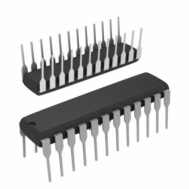
| 产品图片 |
|
| 产品型号 | PCM1808QPWRQ1 |
| rohs | 无铅 / 符合限制有害物质指令(RoHS)规范要求 |
| 产品系列 | 自动,AEC-Q100 |
| 供应商器件封装 | 14-TSSOP |
| 其它名称 | 296-28370-6 |
| 分辨率(位) | 24 b |
| 制造商产品页 | http://www.ti.com/general/docs/suppproductinfo.tsp?distId=10&orderablePartNumber=PCM1808QPWRQ1 |
| 包装 | Digi-Reel® |
| 安装类型 | 表面贴装 |
| 封装/外壳 | 14-TSSOP(0.173",4.40mm 宽) |
| 工作温度 | -40°C ~ 125°C |
| 数据接口 | 串行 |
| 标准包装 | 1 |
| 电压-电源 | 2.7 V ~ 3.6 V,4.5 V ~ 5.5 V |
| 电压源 | 模拟和数字 |
| 类型 | ADC, 音频 |
| 采样率(每秒) | 96k |


PDF Datasheet 数据手册内容提取
PCM1808-Q1 www.ti.com SLES265A–MARCH2011–REVISEDAUGUST2012 SINGLE-ENDED, ANALOG-INPUT 24-BIT, 96-kHz STEREO A/D CONVERTER CheckforSamples:PCM1808-Q1 FEATURES • Package:14-PinTSSOP 1 • QualifiedforAutomotiveApplications 23 DESCRIPTION • 24-BitDelta-SigmaStereoA/DConverter The PCM1808-Q1 is high-performance, low-cost, • Single-EndedVoltageInput:3Vp-p single-chip, stereo analog-to-digital converter with • HighPerformance: single-ended analog voltage input. The PCM1808-Q1 uses a delta-sigma modulator with 64-times – THD+N: –93dB(Typical) oversampling and includes a digital decimation filter – SNR:99dB(Typical) and high-pass filter that removes the dc component – DynamicRange:99dB(Typical) of the input signal. For various applications, the • OversamplingDecimationFilter: PCM1808-Q1 supports master and slave mode and twodataformatsinserialaudiointerface. – OversamplingFrequency: ×64 The PCM1808-Q1 supports the power-down and – Pass-BandRipple: ±0.05dB resetfunctionbymeansofhaltingthesystemclock. – Stop-BandAttenuation:–65dB The PCM1808-Q1 is suitable for wide variety of cost- – On-ChipHigh-PassFilter:0.91Hz(48kHz) sensitive consumer applications where good • FlexiblePCMAudioInterface performance and operation with a 5-V analog supply – Master/SlaveModeSelectable and 3.3-V digital supply is required. The PCM1808- – DataFormats:24-BitI2S,24-BitLeft- Q1 is fabricated using a highly advanced CMOS process and is available in a small, 14-pin TSSOP Justified package. • PowerDownandResetbyHaltingSystem Clock • AnalogAntialiasLPFIncluded • SamplingRate:8kHz–96kHz • SystemClock:256f ,384f ,512f S S S • DualPowerSupplies: – 5-VforAnalog – 3.3-VforDigital 1 Pleasebeawarethatanimportantnoticeconcerningavailability,standardwarranty,anduseincriticalapplicationsof TexasInstrumentssemiconductorproductsanddisclaimerstheretoappearsattheendofthisdatasheet. SystemTwo,AudioPrecisionaretrademarksofAudioPrecision,Inc. 2 Allothertrademarksarethepropertyoftheirrespectiveowners. 3 PRODUCTIONDATAinformationiscurrentasofpublicationdate. Copyright©2011–2012,TexasInstrumentsIncorporated Products conform to specifications per the terms of the Texas Instruments standard warranty. Production processing does not necessarilyincludetestingofallparameters.
PCM1808-Q1 SLES265A–MARCH2011–REVISEDAUGUST2012 www.ti.com This integrated circuit can be damaged by ESD. Texas Instruments recommends that all integrated circuits be handled with appropriateprecautions.Failuretoobserveproperhandlingandinstallationprocedurescancausedamage. ESDdamagecanrangefromsubtleperformancedegradationtocompletedevicefailure.Precisionintegratedcircuitsmaybemore susceptibletodamagebecauseverysmallparametricchangescouldcausethedevicenottomeetitspublishedspecifications. ABSOLUTE MAXIMUM RATINGS overoperatingfree-airtemperaturerange(unlessotherwisenoted) (1) PCM1808-Q1 Analogsupplyvoltage,V –0.3Vto6.5V CC Digitalsupplyvoltage,V –0.3Vto4V DD Groundvoltagedifferences,AGND,DGND ±0.1V Digitalinputvoltage,LRCK,BCK,DOUT –0.3Vto(V +0.3V)<4V DD Digitalinputvoltage,SCKI,MD0,MD1,FMT –0.3Vto6.5V Analoginputvoltage,V L,V R,V –0.3Vto(V +0.3V)<6.5V IN IN REF CC Inputcurrent(anypinsexceptsupplies) ±10mA Ambienttemperatureunderbias,T –40°Cto125°C A Storagetemperature,T –55°Cto150°C stg Junctiontemperature,T 150°C J Leadtemperature(soldering) 260°C,5s Packagetemperature(reflow,peak) 260°C (1) StressesbeyondthoselistedunderAbsoluteMaximumRatingsmaycausepermanentdamagetothedevice.Thesearestressratings only,andfunctionaloperationofthedeviceattheseoranyotherconditionsbeyondthoseindicatedunderRecommendedOperating Conditionsisnotimplied.Exposuretoabsolute-maximum-ratedconditionsforextendedperiodsmayaffectdevicereliability. RECOMMENDED OPERATING CONDITIONS overoperatingfree-airtemperaturerange(unlessotherwisenoted) MIN NOM MAX UNIT Analogsupplyvoltage,V 4.5 5 5.5 V CC Digitalsupplyvoltage,V 2.7 3.3 3.6 V DD Analoginputvoltage,fullscale(–0dB) V =5V 2.93 3 3.23 Vp-p CC Digitalinputlogicfamily TTLcompatible Digitalinputclockfrequency,systemclock 2.048 49.152 MHz Digitalinputclockfrequency,samplingclock 8 96 kHz Digitaloutputloadcapacitance 20 pF Operatingfree-airtemperature,T –40 125 °C A 2 Copyright©2011–2012,TexasInstrumentsIncorporated
PCM1808-Q1 www.ti.com SLES265A–MARCH2011–REVISEDAUGUST2012 ELECTRICAL CHARACTERISTICS AllspecificationsatT =25°C,V =5V,V =3.3V,mastermode,f =48kHz,systemclock=512f ,24-bitdata,unless A CC DD S S otherwisenoted PARAMETER TESTCONDITIONS MIN TYP MAX UNIT Resolution 24 Bits DATAFORMAT Audiodatainterfaceformat I2S,left-justified Audiodatabitlength 24 Bits Audiodataformat MSB-first,2scomplement f Samplingfrequency 8 48 96 kHz S 256f 2.048 12.288 24.576 S Systemclockfrequency, –40°C≤T ≤125°C(1) 384fS 3.072 18.432 36.864 MHz A 512f 4.096 24.576 49.152 S INPUTLOGIC V (2) 2 V IH DD VIL (2) Inputlogiclevel, 0 0.8 VIH (4) (5) –40°C≤TA≤125°C(3) 2 5.5 VDC V (4) (5) 0 0.8 IL I (4) V =V ±10 IH IN DD I (4) V =0V ±10 IL IN Inputlogiccurrent at25°C 65 100 μA I (2) (5) V =V IH IN DD –40°C≤T ≤125°C 65 150 A I (2) (5) V =0V ±10 IL IN OUTPUTLOGIC at25°C 2.8 V (6) I =–4mA OH Outputlogiclevel(3) OUT –40°C≤T ≤125°C 2.7 VDC A V (6) I =4mA,–40°C≤T ≤125°C 0.5 OL OUT A DCACCURACY,–40°C≤T ≤125°C A Gainmismatch,channel-to- %of ±1 ±3 channel FSR %of Gainerror ±3 ±6 FSR DYNAMICPERFORMANCE (7) at25°C –93 –87 V =–0.5dB,f =48kHz IN S –40°C≤T ≤125°C –93 –85 A THD+N Totalharmonicdistortion+ V =–0.5dB,f =96kHz (8) –87 dB noise IN S V =–60dB,f =48kHz –37 IN S V =–60dB,f =96kHz (8) –39 IN S at25°C 95 99 f =48kHz,A-weighted S Dynamicrange –40°C≤T ≤125°C 93 99 dB A f =96kHz,A-weighted (8) 101 S at25°C 95 99 f =48kHz,A-weighted S S/N Signal-to-noiseratio –40°C≤T ≤125°C 93 99 dB A f =96kHz,A-weighted (8) 101 S (1) 384f wheref =96kHz,and512wheref =48kHzand96kHzarefunctionallytested.Otheroptionsarespecifiedbydesign. s s s (2) Pins7,8:LRCK,BCK(Schmitt-triggerinput,with50-kΩtypicalpulldownresistor,inslavemode) (3) Specifiedbydesign (4) Pin6:SCKI(Schmitt-triggerinput,5-Vtolerant) (5) Pins10–12:MD0,MD1,FMT(Schmitt-triggerinput,with50-kΩtypicalpulldownresistor,5-Vtolerant) (6) Pins7–9:LRCK,BCK(inmastermode),DOUT (7) AnalogperformancespecificationsaretestedusingaSystemTwo™audiomeasurementsystembyAudioPrecision™with400-HzHPF and20-kHzLPFinRMSmode. (8) f =96kHz,systemclock=256f . S S Copyright©2011–2012,TexasInstrumentsIncorporated 3
PCM1808-Q1 SLES265A–MARCH2011–REVISEDAUGUST2012 www.ti.com ELECTRICAL CHARACTERISTICS (continued) AllspecificationsatT =25°C,V =5V,V =3.3V,mastermode,f =48kHz,systemclock=512f ,24-bitdata,unless A CC DD S S otherwisenoted PARAMETER TESTCONDITIONS MIN TYP MAX UNIT at25°C 93 97 f =48kHz S Channelseparation –40°C≤T ≤125°C 91 97 dB A f =96kHz (8) 91 S ANALOGINPUT Inputvoltage, 0.58V 0.6V 0.65V Vp-p –40°C≤T ≤125°C CC CC CC A Centervoltageinputrange, 0.2V 0.5V 0.8V V –40°C≤T ≤125°C CC CC CC A Inputimpedance 60 kΩ Antialiasingfilterfrequency –3dB 1.3 MHz response DIGITALFILTERPERFORMANCE,–40°C≤T ≤125°C (3) A Passband 0.454f Hz S Stopband 0.583f Hz S Pass-bandripple ±0.05 dB Stop-bandattenuation –65 dB Delaytime 17.4/f S 0.019 HPFfrequencyresponse –3dB f /1000 S POWERSUPPLYREQUIREMENTS VCC Voltagerange, 4.5 5 5.5 VDC VDD –40°C≤TA≤125°C 2.7 3.3 3.6 f =48kHz,96kHz,–40°C≤T ≤125°C (10) 8.6 11 mA S A I CC Powereddown (11) 1 μA at25°C 5.9 8 Supplycurrent (9) f =48kHz mA S –40°C≤T ≤125°C 5.9 10 A I DD f =96kHz (10) 10.2 mA S Powereddown (11) 150 μA f =48kHz 62 81 S mW Powerdissipation (9) f =96kHz (10) 77 S Powereddown (11) 500 μW TEMPERATURERANGE T Operationtemperature –40 125 °C A θ Thermalresistance 170 °C/W JA (9) MinimumloadonLRCK(pin7),BCK(pin8),DOUT(pin9) (10) f =96kHz,systemclock=256f . S S (11) Power-downandresetfunctionsenabledbyhaltingSCKI,BCK,LRCK. 4 Copyright©2011–2012,TexasInstrumentsIncorporated
PCM1808-Q1 www.ti.com SLES265A–MARCH2011–REVISEDAUGUST2012 PIN ASSIGNMENTS PW PACKAGE (TOP VIEW) VREF 1 14 VINR AGND 2 13 VINL VCC 3 12 FMT VDD 4 11 MD1 DGND 5 10 MD0 SCKI 6 9 DOUT LRCK 7 8 BCK P0032-02 TERMINALFUNCTIONS TERMINAL I/O DESCRIPTION NAME PIN AGND 2 – AnalogGND BCK 8 I/O Audiodatabitclockinput/output (1) DGND 5 – DigitalGND DOUT 9 O Audiodatadigitaloutput FMT 12 I Audiointerfaceformatselect (2) LRCK 7 I/O Audiodatalatchenableinput/output (1) MD0 10 I Audiointerfacemodeselect0 (2) MD1 11 I Audiointerfacemodeselect1 (2) SCKI 6 I Systemclockinput;256f ,384f or512f (3) S S S V 3 – Analogpowersupply,5-V CC V 4 – Digitalpowersupply,3.3-V DD V L 13 I Analoginput,L-channel IN V R 14 I Analoginput,R-channel IN V 1 – Referencevoltagedecoupling(=0.5V ) REF CC (1) Schmitt-triggerinputwithinternalpulldown(50-kΩ,typical) (2) Schmitt-triggerinputwithinternalpulldown(50-kΩ,typical),5-Vtolerant (3) Schmitt-triggerinput,5-Vtolerant Copyright©2011–2012,TexasInstrumentsIncorporated 5
PCM1808-Q1 SLES265A–MARCH2011–REVISEDAUGUST2012 www.ti.com FunctionalBlockDiagram VINL AnLtiPaFlias DMelotad-uSlaigtomra BCK LRCK Serial ×1/64 Interface DOUT Decimation VREF Reference Filter with Mode/ FMT High-Pass Filter Format Control MD1 VINR AnLtiPaFlias DMelotad-uSlaigtomra MD0 Power Supply Clock and Timing Control SCKI VCC AGND DGND VDD B0004-10 TYPICAL PERFORMANCE CURVES OF INTERNAL FILTERS AllspecificationsatT =25°C,V =5V,V =3.3V,mastermode,f =48kHz,systemclock=512f ,24-bitdata,unless A CC DD S S otherwisenoted. DECIMATION FILTER FREQUENCY RESPONSE OVERALLCHARACTERISTICS STOP-BANDATTENUATIONCHARACTERISTICS 50 0 −10 0 −20 −30 B B d −50 d −40 − − e e d d −50 u u mplit −100 mplit −60 A A −70 −150 −80 −90 −200 −100 0 8 16 24 32 0.00 0.25 0.50 0.75 1.00 Normalized Frequency [× fS] Frequency [× fS] G001 G002 Figure1. Figure2. 6 Copyright©2011–2012,TexasInstrumentsIncorporated
PCM1808-Q1 www.ti.com SLES265A–MARCH2011–REVISEDAUGUST2012 TYPICAL PERFORMANCE CURVES OF INTERNAL FILTERS (Continued) AllspecificationsatT =25°C,V =5V,V =3.3V,mastermode,f =48kHz,systemclock=512f ,24-bitdata,unless A CC DD S S otherwisenoted. DECIMATION FILTER FREQUENCY RESPONSE (Continued) PASS-BANDRIPPLECHARACTERISTICS TRANSITIONBANDCHARACTERISTICS 0.2 0 −1 0.0 −2 −3 −0.2 B B d d −4 e − e − –4.13 dB at 0.5 fS d −0.4 d −5 u u mplit mplit −6 A A −0.6 −7 −8 −0.8 −9 −1.0 −10 0.0 0.1 0.2 0.3 0.4 0.5 0.6 0.45 0.46 0.47 0.48 0.49 0.50 0.51 0.52 0.53 0.54 0.55 Normalized Frequency [× fS] Normalized Frequency [× fS] G003 G004 Figure3. Figure4. HIGH-PASS FILTER FREQUENCY RESPONSE HPFSTOP-BANDCHARACTERISTICS HPFPASS-BANDCHARACTERISTICS 0 0.2 −10 0.0 −20 −30 −0.2 B B d −40 d − − e e d −50 d −0.4 u u mplit −60 mplit A A −0.6 −70 −80 −0.8 −90 −100 −1.0 0.0 0.1 0.2 0.3 0.4 0 1 2 3 4 Normalized Frequency [× fS/1000] Normalized Frequency [× fS/1000] G005 G006 Figure5. Figure6. Copyright©2011–2012,TexasInstrumentsIncorporated 7
PCM1808-Q1 SLES265A–MARCH2011–REVISEDAUGUST2012 www.ti.com TYPICAL PERFORMANCE CURVES AllspecificationsatT =25°C,V =5V,V =3.3V,mastermode,f =48kHz,systemclock=512f ,24-bitdata,unless A CC DD S S otherwisenoted. THD+N DYNAMICRANGEANDSNR vs vs TEMPERATURE TEMPERATURE −87 105 B d − −88 104 e s Noi −89 B 103 + d on −90 R − 102 storti −91 d SN 101 nic Di −92 ge an 100 Dynamic Range o n m −93 Ra 99 SNR al Har −94 amic 98 − Tot −95 Dyn 97 N D + −96 96 H T −97 95 −50 −25 0 25 50 75 100 −50 −25 0 25 50 75 100 TA − Free-Air Temperature − °C TA − Free-Air Temperature − °C G007 G008 Figure7. Figure8. THD+N DYNAMICRANGEANDSNR vs vs SUPPLYVOLTAGE SUPPLYVOLTAGE −87 105 B d − −88 104 e s oi −89 103 N B + d on −90 R − 102 storti −91 d SN 101 Di an nic −92 ge 100 Dynamic Range o n m −93 Ra 99 SNR ar c al H −94 ami 98 − Tot −95 Dyn 97 N D + −96 96 H T −97 95 4.25 4.50 4.75 5.00 5.25 5.50 5.75 4.25 4.50 4.75 5.00 5.25 5.50 5.75 VCC − Supply Voltage − V VCC − Supply Voltage − V G009 G010 Figure9. Figure10. 8 Copyright©2011–2012,TexasInstrumentsIncorporated
PCM1808-Q1 www.ti.com SLES265A–MARCH2011–REVISEDAUGUST2012 TYPICAL PERFORMANCE CURVES (Continued) AllspecificationsatT =25°C,V =5V,V =3.3V,mastermode,f =48kHz,systemclock=512f ,24-bitdata,unless A CC DD S S otherwisenoted. THD+N DYNAMICRANGEANDSNR vs vs f CONDITION f CONDITION SAMPLE SAMPLE −87 105 B − d −88 104 Dynamic Range e SNR s oi −89 103 N B + d on −90 R − 102 storti −91 d SN 101 Di an c −92 e 100 ni g o n m −93 Ra 99 ar c al H −94 ami 98 − Tot −95 Dyn 97 D + N −96 ((12)) SSyysstteemm CClloocckk == 358142 ffSS 96 ((12)) SSyysstteemm CClloocckk == 358142 ffSS H (3) System Clock = 256 fS (3) System Clock = 256 fS T −97 95 44.1(1) 48(2) 96(3) 44.1(1) 48(2) 96(3) fSAMPLE Condition − kHz fSAMPLE Condition − kHz G011 G012 Figure11. Figure12. OUTPUT SPECTRUM OUTPUTSPECTRUM(–0.5dB,N=8192) OUTPUTSPECTRUM(–60dB,N=8192) 0 0 Input Level = −0.5 dB Input Level = −60 dB Data Points = 8192 Data Points = 8192 −20 −20 −40 −40 B B d d − −60 − −60 e e d d u u plit −80 plit −80 m m A A −100 −100 −120 −120 −140 −140 0 5 10 15 20 0 5 10 15 20 f − Frequency − kHz f − Frequency − kHz G013 G014 Figure13. Figure14. Copyright©2011–2012,TexasInstrumentsIncorporated 9
PCM1808-Q1 SLES265A–MARCH2011–REVISEDAUGUST2012 www.ti.com TYPICAL PERFORMANCE CURVES (Continued) AllspecificationsatT =25°C,V =5V,V =3.3V,mastermode,f =48kHz,systemclock=512f ,24-bitdata,unless A CC DD S S otherwisenoted. OUTPUT SPECTRUM (Continued) THD+N vs SIGNALLEVEL 0 B d − −10 e s oi −20 N + n −30 o storti −40 Di c −50 ni o m −60 ar H al −70 ot T − −80 N D + −90 H T −100 −100−90 −80 −70 −60 −50 −40 −30 −20 −10 0 Signal Level − dB G015 Figure15. SUPPLY CURRENT SUPPLYCURRENT vs f CONDITION SAMPLE 15 ICC IDD A m − nt e 10 urr C y pl p u S − D D 5 d I n a C C I (1) System Clock = 384 fS (2) System Clock = 512 fS (3) System Clock = 256 fS 0 44.1(1) 48(2) 96(3) fSAMPLE Condition − kHz G016 Figure16. 10 Copyright©2011–2012,TexasInstrumentsIncorporated
PCM1808-Q1 www.ti.com SLES265A–MARCH2011–REVISEDAUGUST2012 SYSTEM CLOCK The PCM1808-Q1 supports 256 f , 384 f and 512 f as system clock, where f is the audio sampling frequency. S S S S ThesystemclockmustbesuppliedonSCKI(pin6). The PCM1808-Q1 has a system clock detection circuit which automatically senses if the system clock is operating at 256 f , 384 f , or 512 f in slave mode. In master mode, the system clock frequency must be S S S controlled through the serial control port, which uses MD1 (pin 111) and MD0 (pin 10). The system clock is divideddownautomaticallytogeneratefrequenciesof128f and64f ,whichareusedtooperatethedigitalfilter S S andthedelta-sigmamodulator,respectively. Table 1 shows some typical relationships between sampling frequency and system clock frequency, and Figure17showssystemclocktiming. Table1.SamplingFrequencyandSystemClockFrequency SAMPLINGFREQUENCY(kHz) SYSTEMCLOCKFREQUENCY(f )(MHz) SCLK 256f 384f 512f S S S 8 2.048 3.072 4.096 16 4.096 6.144 8.192 32 8.192 12.288 16.384 44.1 11.2896 16.9344 22.5792 48 12.288 18.432 24.576 64 16.384 24.576 32.768 88.2 22.5792 33.8688 45.1584 96 24.576 36.864 49.152 tw(SCKH) tw(SCKL) SCKI 2 V SCKI 0.8 V T0005B07 SYMBOL PARAMETER MIN MAX UNIT t Systemclockpulseduration,HIGH 8 ns w(SCKH) t Systemclockpulseduration,LOW 8 ns w(SCKL) Systemclockdutycycle 40% 60% Figure17. SystemClockTiming FADE-IN AND FADE-OUT FUNCTIONS The PCM1808-Q1 has fade-in and fade-out functions on DOUT (pin 9) to avoid pop noise, and the functions come into operation in some cases as described in several following sections. The level changes from 0 dB to mute or mute to 0 dB are performed using calculated pseudo S-shaped characteristics with zero-cross detection. Because of the zero-cross detection, the time needed for the fade in and fade out depends on the analog input frequency (f ). It takes 48/f until processing is completed. If there is no zero cross during 8192/f , DOUT is in in S faded in or out by force during 48/f (TIME OUT). Figure 18 illustrates the fade-in and fade-out operation S processing. Copyright©2011–2012,TexasInstrumentsIncorporated 11
PCM1808-Q1 SLES265A–MARCH2011–REVISEDAUGUST2012 www.ti.com Fade-In Complete Fade-Out Start Fade-In Start Fade-Out Complete DOUT BPZ (Contents) 48/fin or 48/fS 48/fin or 48/fS T0080-01 Figure18. Fade-InandFade-OutOperations POWER ON The PCM1808-Q1 has an internal power-on-reset circuit, and initialization (reset) is performed automatically when the power supply (V ) exceeds 2.2 V (typical). While V < 2.2 V (typical), and for 1024 system-clock DD DD counts after V > 2.2 V (typical), the PCM1808-Q1 stays in the reset state and the digital output is forced to DD zero. The digital output is valid after the reset state is released and the time of 8960/f has elapsed. Because the S fade-in operation is performed, it takes additional time of 48/f or 48/f until the data corresponding to the analog in S inputsignalisobtained.Figure19illustratesthepower-ontimingandthedigitaloutput. 2.6 V VDD 2.2 V 1.8 V Reset Reset Release Internal Operation Reset 1024 System Clocks 8960/fS System Clock DOUT Zero Data Normal Data Fade-In Complete Fade-In Start DOUT BPZ (Contents) 48/fin or 48/fS T0014-09 Figure19. Power-OnTiming 12 Copyright©2011–2012,TexasInstrumentsIncorporated
PCM1808-Q1 www.ti.com SLES265A–MARCH2011–REVISEDAUGUST2012 CLOCK-HALT POWER-DOWN AND RESET FUNCTION The PCM1808-Q1 has a power-down and reset function, which is triggered by halting SCKI (pin 6) in both masterandslavemodes.Thefunctionisavailableanytimeafterpoweron.Resetandpowerdownareperformed automatically 4 μs (minimum) after SCKI is halted. While the clock-halt reset is asserted, the PCM1808-Q1 stays in the reset and power-down mode, and DOUT (pin 9) is forced to zero. SCKI must be supplied to release the reset and power-down mode. The digital output is valid after the reset state is released and the time of 1024 SCKI + 8960/f has elapsed. Because the fade-in operation is performed, it takes additional time of 48/f or 48/f S in S until the level corresponding to the analog input signal is obtained. Figure 20 illustrates the clock-halt reset timing. To avoid ADC performance degradation, BCK (pin 8) and LRCK (pin 7) are required to synchronize with SCKI within 4480/f after SCKI is resumed. If it takes more than 4480/f for BCK and LRCK to synchronize with SCKI, S S SCKI should be masked until the synchronization is achieved again, taking care of glitch and jitter. See the typicalcircuitconnectiondiagram,Figure26. To avoid ADC performance degradation, the clock-halt reset also should be asserted when system clock SCKIor theaudiointerfaceclocksBCKandLRCK(samplingratef )arechangedonthefly. S SCKI Halt SCKI Resume SCKI Fixed to Low or High t(CKR) Reset: t(RST) Clock-Halt Reset Reset Release: t(REL) Internal Operation Operation Reset DOUT Normal Data Zero Data Normal Data Fade-In Complete Fade-In Start Normal Data DOUT BPZ (Contents) 48/fin or 48/fS T0081-01 SYMBOL PARAMETER MIN MAX UNIT t DelaytimefromSCKIhalttointernalreset 4 μs (CKR) t DelaytimefromSCKIresumetoresetrelease 1024SCKI μs (RST) t DelaytimefromresetreleasetoDOUToutput 8960/f μs (REL) S Figure20. Clock-HaltPower-DownandResetTiming Copyright©2011–2012,TexasInstrumentsIncorporated 13
PCM1808-Q1 SLES265A–MARCH2011–REVISEDAUGUST2012 www.ti.com SERIAL AUDIO DATA INTERFACE ThePCM1808-Q1interfacestheaudiosystemthroughLRCK(pin7),BCK(pin8),andDOUT(pin9). INTERFACEMODE The PCM1808-Q1 supports master mode and slave mode as interface modes, which are selected by MD1 (pin 11)andMD0(pin10),asshowninTable2.MD1andMD0mustbesetpriortopoweron. In master mode, the PCM1808-Q1 provides the timing of serial audio data communications between the PCM1808-Q1 and the digital audio processor or external circuit. While in slave mode, the PCM1808-Q1 receives thetimingfordatatransferfromanexternalcontroller. Table2.InterfaceModes MD1(Pin11) MD0(Pin10) INTERFACEMODE Low Low Slavemode(256f ,384f ,512f autodetection) S S S Low High Mastermode(512f ) S High Low Mastermode(384f ) S High High Mastermode(256f ) S Mastermode In master mode, BCK and LRCK work as output pins, and these pins are controlled by timing which is generated intheclockcircuitofthePCM1808-Q1.ThefrequencyofBCKisfixedat64BCK/frame. Slavemode In slave mode, BCK and LRCK work as input pins. The PCM1808-Q1 accepts 64-BCK/frame or 48-BCK/frame format(onlyfora384-f systemclock),not32-BCK/frameformat. S DATAFORMAT The PCM1808-Q1 supports two audio data formats in both master and slave modes. The data formats are selected by FMT (pin 12), as shown in Table 3. Figure 21 illustrates the data formats in slave mode and master mode. Table3.DataFormat FORMATNO. FMT(Pin12) FORMAT 0 Low I2S,24-bit 1 High Left-justified,24-bit 14 Copyright©2011–2012,TexasInstrumentsIncorporated
PCM1808-Q1 www.ti.com SLES265A–MARCH2011–REVISEDAUGUST2012 FORMAT 0: FMT = LOW 24-Bit, MSB-First, I2S LRCK Left-Channel Right-Channel BCK DOUT 1 2 3 22 23 24 1 2 3 22 23 24 MSB LSB MSB LSB FORMAT 1: FMT = HIGH 24-Bit, MSB-First, Left-Justified LRCK Left-Channel Right-Channel BCK DOUT 1 2 3 22 23 24 1 2 3 22 23 24 1 MSB LSB MSB LSB T0016-17 Figure21. AudioDataFormat(LRCKandBCKWorkasInputsinSlaveMode andasOutputsinMasterMode) Copyright©2011–2012,TexasInstrumentsIncorporated 15
PCM1808-Q1 SLES265A–MARCH2011–REVISEDAUGUST2012 www.ti.com INTERFACETIMING Figure22andFigure23illustratetheinterfacetiminginslavemodeandmastermode,respectively. t(LRCP) LRCK 1.4 V t(BCKL) t(LRSU) t(BCKH) t(LRHD) BCK 1.4 V t(BCKP) t(CKDO) t(LRDO) DOUT 0.5 VDD T0017-02 SYMBOL PARAMETER MIN TYP MAX UNIT t BCKperiod 1/(64f ) ns (BCKP) S t BCKpulseduration,HIGH 1.5×t ns (BCKH) (SCKI) t BCKpulseduration,LOW 1.5×t ns (BCKL) (SCKI) t LRCKsetuptimetoBCKrisingedge 50 ns (LRSU) t LRCKholdtimetoBCKrisingedge 10 ns (LRHD) t LRCKperiod 10 μs (LRCP) t Delaytime,BCKfallingedgetoDOUTvalid –10 40 ns (CKDO) t Delaytime,LRCKedgetoDOUTvalid –10 40 ns (LRDO) t Risetimeofallsignals 20 ns r t Falltimeofallsignals 20 ns f NOTE: Timing measurement reference level is 1.4 V for input and 0.5 V for output. Rise and fall times are from 10% to DD 90%oftheinput/outputsignalswing.LoadcapacitanceofDOUTis20pF.t istheSCKIperiod. (SCKI) Figure22. AudioDataInterfaceTiming(SlaveMode:LRCKandBCKWorkasInputs) 16 Copyright©2011–2012,TexasInstrumentsIncorporated
PCM1808-Q1 www.ti.com SLES265A–MARCH2011–REVISEDAUGUST2012 t(LRCP) LRCK 0.5 VDD t(BCKL) t(BCKH) t(CKLR) BCK 0.5 VDD t(BCKP) t(CKDO) t(LRDO) DOUT 0.5 VDD T0018-02 SYMBOL PARAMETER MIN TYP MAX UNIT t BCKperiod 150 1/(64f ) 2000 ns (BCKP) S t BCKpulseduration,HIGH 65 1200 ns (BCKH) t BCKpulseduration,LOW 65 1200 ns (BCKL) t Delaytime,BCKfallingedgetoLRCKvalid –10 20 ns (CKLR) t LRCKperiod 10 1/f 125 μs (LRCP) S t Delaytime,BCKfallingedgetoDOUTvalid –10 20 ns (CKDO) t Delaytime,LRCKedgetoDOUTvalid –10 20 ns (LRDO) t Risetimeofallsignals 20 ns r t Falltimeofallsignals 20 ns f NOTE: Timingmeasurementreferencelevel is 0.5V .Riseandfalltimesarefrom10% to90% oftheinput/output signal DD swing.Loadcapacitanceofallsignalsis20pF. Figure23. AudioDataInterfaceTiming(MasterMode:LRCKandBCKWorkasOutputs) SCKI 1.4 V t(SCKBCK) t(SCKBCK) BCK 0.5 VDD T0074-01 SYMBOL PARAMETER MIN TYP MAX UNIT t Delaytime,SCKIrisingedgetoBCKedge 5 30 ns (SCKBCK) NOTE: Timingmeasurementreferencelevelis1.4Vforinputand0.5V foroutput.LoadcapacitanceofBCKis20pF.This DD timingisappliedwhenSCKIfrequencyislessthan25MHz. Figure24. AudioClockInterfaceTiming(MasterMode:BCKWorksasOutput) Copyright©2011–2012,TexasInstrumentsIncorporated 17
PCM1808-Q1 SLES265A–MARCH2011–REVISEDAUGUST2012 www.ti.com SYNCHRONIZATION WITH DIGITAL AUDIO SYSTEM In slave mode, the PCM1808-Q1 operates under LRCK (pin 7), synchronized with system clock SCKI (pin 6). The PCM1808-Q1 does not require a specific phase relationship between LRCK and SCKI, but does require the synchronizationofLRCKandSCKI. If the relationship between LRCK and SCKI changes more than ±6 BCKs for 64 BCK/frame (±5 BCKs for 48 BCK/frame) during one sample period due to LRCK or SCKI jitter, internal operation of the ADC halts within 1/f S and digital output is forced to zero data (BPZ code) until resynchronization between LRCK and SCKI is established. In the case of changes less than ±5 BCKs for 64 BCK/frame (±4 BCKs for 48 BCK/frame), resynchronization doesnotoccurandthepreviouslydescribeddigitaloutputcontrolanddiscontinuitydonotoccur. Figure 25 illustrates the digital output response for loss of synchronization and resynchronization. During undefined data, the PCM1808-Q1 can generate some noise in the audio signal. Also, the transition of normal data to undefined data creates a discontinuity in the digital output data, which can generate some noise in the audio signal. The digital output is valid after resynchronization completes and the time of 32/f has elapsed. S Because the fade-in operation is performed, it takes additional time of 48/f or 48/f until the level corresponding in S to the analog input signal is obtained. If synchronization is lost during the fade-in or fade-out operation, the operation stops and DOUT (pin 9) is forced to zero data immediately. The fade-in operation resumes from mute afterthetimeof32/f followingresynchronization. S Resynchronization Resynchronization Synchronization Lost Synchronization Lost State of Synchronous Asynchronous Synchronous Asynchronous Synchronous Synchronization 1/fS 32/fS Undefined DOUT Normal Data Zero Data Normal Data Zero Data Normal Data Data Fade-In Complete Fade-In Start Fade-In Restart Normal Data DOUT BPZ (Contents) 32/fS 48/fin or 48/fS 48/fin or 48/fS T0082-01 Figure25. ADCDigitalOutputforLossofSynchronizationandResynchronization 18 Copyright©2011–2012,TexasInstrumentsIncorporated
PCM1808-Q1 www.ti.com SLES265A–MARCH2011–REVISEDAUGUST2012 APPLICATION INFORMATION TYPICAL CIRCUIT CONNECTION DIAGRAM Figure 26 is a typical circuit connection diagram. The antialiasing low-pass filters are integrated on the analog inputs, V L and V R. If the performance of these filters is not adequate for an application, appropriate external IN IN antialiasingfiltersareneeded.ApassiveRCfilter(100Ωand0.01 μFto1kΩand1000pF)generallyisused. PCM1808 (5) C5(3) + + C1(1) 1 VREF VINR 14 R-ch IN + C2(1) 2 AGND VINL 13 L-ch IN C4(2) + 4 m s (min) 5 V 3 VCC FMT 12 High/Low 3.3 V + 4 VDD MD1 11 Pin C3(2) Setting 5 DGND MD0 10 Mask 6 SCKI DOUT 9 X1(4) 7 LRCK BCK 8 PLL170x DSP or Audio Processor S0113-02 (1) C1, C2: A 1-μF electrolytic capacitor gives 2.7 Hz (τ = 1 μF × 60 kΩ) cutoff frequency for the input HPF in normal operationandrequiresapower-onsettlingtimewitha60-mstimeconstantinthepower-oninitializationperiod. (2) C3,C4:Bypasscapacitors,0.1-μFceramicand10-μFelectrolytic,dependingonlayoutandpowersupply (3) C5:0.1-μFceramicand10-μFelectrolyticcapacitorsarerecommended. (4) X1:X1masksthesystemclockinputwhenusingtheclock-haltresetfunctionwithexternalcontrol. (5) Optionalexternalantialiasingfiltercouldberequired,dependingontheapplication. Figure26. TypicalCircuitConnectionDiagram BOARD DESIGN AND LAYOUT CONSIDERATIONS V ,V PINS CC DD The digital and analog power supply lines to the PCM1808-Q1 should be bypassed to the corresponding ground pins with both 0.1-μF ceramic and 10-μF electrolytic capacitors as close to the pins as possible to maximize the dynamicperformanceoftheADC. AGND,DGNDPINS To maximize the dynamic performance of the PCM1808-Q1, the analog and digital grounds are not internally connected. These grounds should have low impedance to avoid digital noise feedback into the analog ground. They should be connected directly to each other under the PCM1808-Q1 package to reduce potential noise problems. V L,V RPINS IN IN V LandV Raresingle-endedinputs.Theantialiaslow-passfiltersareintegratedontheseinputstoremovethe IN IN high-frequency noise outside the audio band. If the performance of these filters is not adequate for an application, appropriate external antialiasing filters are required. A passive RC filter (100 Ω and 0.01 μF to 1 kΩ and1000pF)isgenerallyused. Copyright©2011–2012,TexasInstrumentsIncorporated 19
PCM1808-Q1 SLES265A–MARCH2011–REVISEDAUGUST2012 www.ti.com V PIN REF To ensure low source impedance of the ADC references, 0.1-μF ceramic and 10-μF electrolytic capacitors are recommended between V and AGND. These capacitors should be located as close as possible to the V REF REF pintoreducedynamicerrorsontheADCreferences. DOUTPIN The DOUT pin has a large load-drive capability, but if the DOUT line is long, locating a buffer near the PCM1808-Q1 and minimizing load capacitance is recommended to minimize the digital-analog crosstalk and maximizethedynamicperformanceoftheADC. SYSTEMCLOCK The quality of the system clock can influence dynamic performance, as the PCM1808-Q1 operates based on a system clock. Therefore, it may be necessary to consider the system clock duty, jitter, and the time difference betweensystemclocktransitionandBCKorLRCKtransitioninslavemode. 20 Copyright©2011–2012,TexasInstrumentsIncorporated
PCM1808-Q1 www.ti.com SLES265A–MARCH2011–REVISEDAUGUST2012 REVISION HISTORY ChangesfromOriginal(March,2011)toRevisionA Page • ROCCHANGES:Added2.93minand3.23maxtoanaloginputvoltagerow .................................................................... 2 • ELECCHARCHANGES:Added-40°C≤T ≤125°CtotheheaderforDCaccuracyandtherowsforsystemclock A frequency,inputlogiclevel,andoutputlogiclevel ............................................................................................................... 3 • AddedtestconditionrowtoV =V (inputlogiccurrent)at-40°C≤T ≤125°Cwithtypvalue65andmaxvalue IN DD A 150 ........................................................................................................................................................................................ 3 • AddedtestconditionrowtoI =–4mA(outputlogiclevel)at-40°C≤T ≤125°Cwithaminvalueof2.7;added OUT A testconditionof25°Cwithminvalueof2.8 ......................................................................................................................... 3 • Addedtestconditionof25°CtoV =–0.5dB,f =48kHz(THD+N)withmaxvalueof–87,andaddedrowwith IN S testconditionof-40°C≤T ≤125°Candmaxvalue–85..................................................................................................... 3 A • Addedtestcondition25°Candminvalueof95;addedtestconditionrowfor-40°C≤T ≤125°Cwithminvalueof A 93tof =48kHz,A-weightedrow(dynamicrangeandsignal-to-noise) ............................................................................. 3 S • Addedtestcondition25°Candminvalueof93;addedtestconditionrowfor-40°C≤T ≤125°Cwithminvalueof A 91tof =48kHz(channelseparation) ................................................................................................................................. 4 S • Addedminvalue0.58V andmaxvalue0.65V toinputvoltage;added0.2V minand0.8V maxtocenter CC CC CC CC voltage;changedcentervoltageVreftocentervoltageinputrange .................................................................................... 4 • Added-40°C≤T ≤125°Ctoinputvoltage,centervoltage,digitalfilterperformanceheader,supplycurrent,and A voltagerangerows ............................................................................................................................................................... 4 • Addedtestconditionrowwith-40°C≤T ≤125°Ctof =48kHz(supplycurrent)withatypvalueof5.9andamax A S valueof10 ............................................................................................................................................................................ 4 Copyright©2011–2012,TexasInstrumentsIncorporated 21
PACKAGE OPTION ADDENDUM www.ti.com 6-Feb-2020 PACKAGING INFORMATION Orderable Device Status Package Type Package Pins Package Eco Plan Lead/Ball Finish MSL Peak Temp Op Temp (°C) Device Marking Samples (1) Drawing Qty (2) (6) (3) (4/5) PCM1808QPWRQ1 ACTIVE TSSOP PW 14 2000 Green (RoHS NIPDAU Level-3-260C-168 HR -40 to 125 P1808Q & no Sb/Br) (1) The marketing status values are defined as follows: ACTIVE: Product device recommended for new designs. LIFEBUY: TI has announced that the device will be discontinued, and a lifetime-buy period is in effect. NRND: Not recommended for new designs. Device is in production to support existing customers, but TI does not recommend using this part in a new design. PREVIEW: Device has been announced but is not in production. Samples may or may not be available. OBSOLETE: TI has discontinued the production of the device. (2) RoHS: TI defines "RoHS" to mean semiconductor products that are compliant with the current EU RoHS requirements for all 10 RoHS substances, including the requirement that RoHS substance do not exceed 0.1% by weight in homogeneous materials. Where designed to be soldered at high temperatures, "RoHS" products are suitable for use in specified lead-free processes. TI may reference these types of products as "Pb-Free". RoHS Exempt: TI defines "RoHS Exempt" to mean products that contain lead but are compliant with EU RoHS pursuant to a specific EU RoHS exemption. Green: TI defines "Green" to mean the content of Chlorine (Cl) and Bromine (Br) based flame retardants meet JS709B low halogen requirements of <=1000ppm threshold. Antimony trioxide based flame retardants must also meet the <=1000ppm threshold requirement. (3) MSL, Peak Temp. - The Moisture Sensitivity Level rating according to the JEDEC industry standard classifications, and peak solder temperature. (4) There may be additional marking, which relates to the logo, the lot trace code information, or the environmental category on the device. (5) Multiple Device Markings will be inside parentheses. Only one Device Marking contained in parentheses and separated by a "~" will appear on a device. If a line is indented then it is a continuation of the previous line and the two combined represent the entire Device Marking for that device. (6) Lead/Ball Finish - Orderable Devices may have multiple material finish options. Finish options are separated by a vertical ruled line. Lead/Ball Finish values may wrap to two lines if the finish value exceeds the maximum column width. Important Information and Disclaimer:The information provided on this page represents TI's knowledge and belief as of the date that it is provided. TI bases its knowledge and belief on information provided by third parties, and makes no representation or warranty as to the accuracy of such information. Efforts are underway to better integrate information from third parties. TI has taken and continues to take reasonable steps to provide representative and accurate information but may not have conducted destructive testing or chemical analysis on incoming materials and chemicals. TI and TI suppliers consider certain information to be proprietary, and thus CAS numbers and other limited information may not be available for release. In no event shall TI's liability arising out of such information exceed the total purchase price of the TI part(s) at issue in this document sold by TI to Customer on an annual basis. OTHER QUALIFIED VERSIONS OF PCM1808-Q1 : Addendum-Page 1
PACKAGE OPTION ADDENDUM www.ti.com 6-Feb-2020 •Catalog: PCM1808 NOTE: Qualified Version Definitions: •Catalog - TI's standard catalog product Addendum-Page 2
PACKAGE MATERIALS INFORMATION www.ti.com 31-Jul-2012 TAPE AND REEL INFORMATION *Alldimensionsarenominal Device Package Package Pins SPQ Reel Reel A0 B0 K0 P1 W Pin1 Type Drawing Diameter Width (mm) (mm) (mm) (mm) (mm) Quadrant (mm) W1(mm) PCM1808QPWRQ1 TSSOP PW 14 2000 330.0 12.4 6.9 5.6 1.6 8.0 12.0 Q1 PackMaterials-Page1
PACKAGE MATERIALS INFORMATION www.ti.com 31-Jul-2012 *Alldimensionsarenominal Device PackageType PackageDrawing Pins SPQ Length(mm) Width(mm) Height(mm) PCM1808QPWRQ1 TSSOP PW 14 2000 367.0 367.0 35.0 PackMaterials-Page2
None
None
IMPORTANTNOTICEANDDISCLAIMER TI PROVIDES TECHNICAL AND RELIABILITY DATA (INCLUDING DATASHEETS), DESIGN RESOURCES (INCLUDING REFERENCE DESIGNS), APPLICATION OR OTHER DESIGN ADVICE, WEB TOOLS, SAFETY INFORMATION, AND OTHER RESOURCES “AS IS” AND WITH ALL FAULTS, AND DISCLAIMS ALL WARRANTIES, EXPRESS AND IMPLIED, INCLUDING WITHOUT LIMITATION ANY IMPLIED WARRANTIES OF MERCHANTABILITY, FITNESS FOR A PARTICULAR PURPOSE OR NON-INFRINGEMENT OF THIRD PARTY INTELLECTUAL PROPERTY RIGHTS. These resources are intended for skilled developers designing with TI products. You are solely responsible for (1) selecting the appropriate TI products for your application, (2) designing, validating and testing your application, and (3) ensuring your application meets applicable standards, and any other safety, security, or other requirements. These resources are subject to change without notice. TI grants you permission to use these resources only for development of an application that uses the TI products described in the resource. Other reproduction and display of these resources is prohibited. No license is granted to any other TI intellectual property right or to any third party intellectual property right. TI disclaims responsibility for, and you will fully indemnify TI and its representatives against, any claims, damages, costs, losses, and liabilities arising out of your use of these resources. TI’s products are provided subject to TI’s Terms of Sale (www.ti.com/legal/termsofsale.html) or other applicable terms available either on ti.com or provided in conjunction with such TI products. TI’s provision of these resources does not expand or otherwise alter TI’s applicable warranties or warranty disclaimers for TI products. Mailing Address: Texas Instruments, Post Office Box 655303, Dallas, Texas 75265 Copyright © 2020, Texas Instruments Incorporated