ICGOO在线商城 > 光电元件 > 红外,UV,可见光发射器 > OP290A

 Datasheet下载
- 型号: OP290A
- 制造商: OPTEK
- 库位|库存: xxxx|xxxx
- 要求:
| 数量阶梯 | 香港交货 | 国内含税 |
| +xxxx | $xxxx | ¥xxxx |
查看当月历史价格
查看今年历史价格
OP290A产品简介:
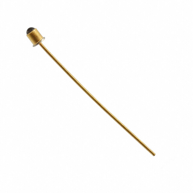
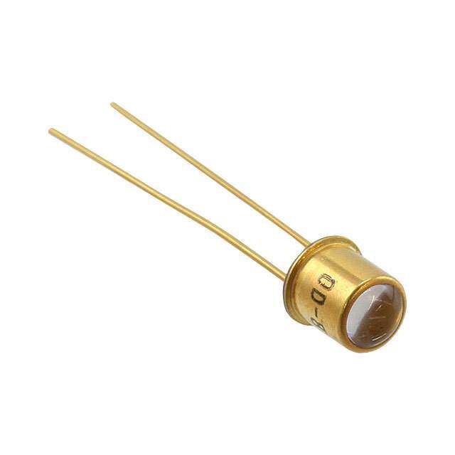
ICGOO电子元器件商城为您提供OP290A由OPTEK设计生产,在icgoo商城现货销售,并且可以通过原厂、代理商等渠道进行代购。 OP290A价格参考¥4.77-¥5.13。OPTEKOP290A封装/规格:红外,UV,可见光发射器, Infrared (IR) Emitter 890nm 4V 150mA 50° T 1 3/4。您可以下载OP290A参考资料、Datasheet数据手册功能说明书,资料中有OP290A 详细功能的应用电路图电压和使用方法及教程。
TT Electronics/Optek Technology品牌的OP290A是一种红外发射器,广泛应用于各类电子设备和系统中。以下是其主要应用场景:

1. 遥控器:OP290A可用于电视、空调、音响等家用电器的遥控器中,作为信号发射元件,通过红外信号实现对设备的无线控制。

2. 红外通信:在短距离数据传输中,如早期的手机或PDA之间的红外数据交换(IrDA协议),OP290A可以作为红外信号的发射源。

3. 安防监控:在夜视摄像头或运动传感器中,OP290A可提供不可见的红外光源,用于增强低光条件下的物体检测或图像捕捉。

4. 接近传感器:结合红外接收器,OP290A可组成接近传感器,用于检测物体的存在或距离,常见于智能手机、自动感应水龙头或工业自动化设备。

5. 障碍物检测:在机器人或自动化设备中,OP290A可用作红外发射器,与接收器配合实现障碍物检测功能,帮助设备避开障碍。

6. 消费电子产品:如玩具、智能家居设备中的红外控制模块,OP290A可用于实现简单的指令发送或交互功能。

7. 工业应用:在流水线检测、包装计数或物料分拣系统中,OP290A可作为红外光源,与其他元件配合完成自动化任务。

8. 医疗设备:在某些非侵入式医疗监测设备中,例如脉搏血氧仪,OP290A可能被用作红外光源以测量血液参数。

总之,OP290A凭借其高效稳定的红外发射性能,在需要红外信号传输、检测或照明的各种场景中发挥重要作用。
| 参数 | 数值 |
| 产品目录 | |
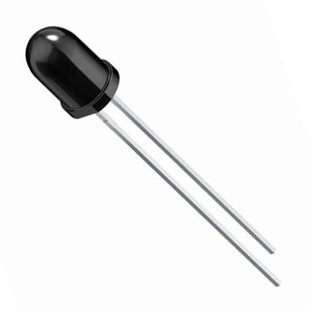
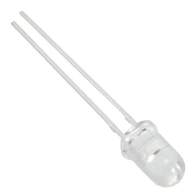
| 描述 | LED IR 5MM 890NM PLASTIC红外发射源 IR EMITTING DIODE |
| 产品分类 | |
| 品牌 | TT Electronics/Optek Technology |
| 产品手册 | |
| 产品图片 |
|
| rohs | 符合RoHS无铅 / 符合限制有害物质指令(RoHS)规范要求 |
| 产品系列 | 红外发射源,Optek / TT Electronics OP290A- |
| 数据手册 | |
| 产品型号 | OP290A |
| 不同If时的辐射强度(Ie)(最小值) | - |
| 产品培训模块 | http://www.digikey.cn/PTM/IndividualPTM.page?site=cn&lang=zhs&ptm=12167 |
| 产品目录页面 | |
| 产品种类 | 红外发射源 |
| 其它名称 | 365-1056 |
| 功率额定值 | 1.11 W |
| 包装 | 散装 |
| 商标 | Optek / TT Electronics |
| 安装类型 | 通孔 |
| 安装风格 | Through Hole |
| 封装 | Bulk |
| 封装/外壳 | T 1 3/4 |
| 封装/箱体 | T-1 3/4 |
| 射束角 | 50 deg |
| 工厂包装数量 | 100 |
| 显示角 | 25 deg |
| 最大工作温度 | + 100 C |
| 最大正向电流 | 150 mA |
| 最小工作温度 | - 40 C |
| 朝向 | 顶视图 |
| 标准包装 | 100 |
| 正向电压 | 4 V |
| 波长 | 890nm |
| 照明颜色 | Infrared |
| 电压-正向(Vf)(典型值) | 4V |
| 电流-DC正向(If) | 150mA |
| 视角 | 50° |
| 透镜形状 | Circular |


- 商务部:美国ITC正式对集成电路等产品启动337调查
- 曝三星4nm工艺存在良率问题 高通将骁龙8 Gen1或转产台积电
- 太阳诱电将投资9.5亿元在常州建新厂生产MLCC 预计2023年完工
- 英特尔发布欧洲新工厂建设计划 深化IDM 2.0 战略
- 台积电先进制程称霸业界 有大客户加持明年业绩稳了
- 达到5530亿美元!SIA预计今年全球半导体销售额将创下新高
- 英特尔拟将自动驾驶子公司Mobileye上市 估值或超500亿美元
- 三星加码芯片和SET,合并消费电子和移动部门,撤换高东真等 CEO
- 三星电子宣布重大人事变动 还合并消费电子和移动部门
- 海关总署:前11个月进口集成电路产品价值2.52万亿元 增长14.8%


PDF Datasheet 数据手册内容提取
OP290 Series Features: Choice of narrow or wide irradiance pattern Choice of power ranges Choice of T-1¾, TO-18 or T-46 package Higher power output than GaAs at equivalent LEDs Description: Each device in this series, is a gallium aluminum arsenide infrared Light Emitting Diode (LED) that is molded in an IR- transmissive package with a wavelength centered at 890 nm, which closely matches the spectral response of silicon phototransistors, except for OP298 (AA, AB, AC, AD), which has either an 850 nm or 875 nm center wavelength. For identification purposes, each LED anode lead is longer than the cathode lead. Package T-1¾ devices include: OP290, OP291, OP292, OP294, OP295, OP296, OP297, OP299 (A, B, C) and OP297FAB, Plastic Package TO-18 or TO-46 devices include: OP293 and OP298 (A, B, C, AA, AD). Each OP290, OP291 and OP292 series come in three electrical parameters options A, B and C. The OP290 series forward current is specified under pulse conditions up to 1.5 amps, the OP291 series forward current is specified under pulse conditions up to 100 milliamps and the OP292 series forward current is specified under pulse conditions up to 1 amp. The Cathode Lead length is 0.06” (1.52 mm) shorter than the Anode Lead. The silver-copper lead frame offers excellent thermal characteristics. Each OP293 and OP298 series come in three electrical parameter options A, B and C. The OP293 series has an included emission angle of 60° while the OP298 series has an included emission angle of 25°. The Cathode Lead length is 0.06” (1.52 mm) shorter than the Anode Lead. These devices, which come in a variety of power ranges offering a low cost replacement for TO-18 or TO-46 hermetic packages. Each OP298 series come with a high irradiance output versions with four electrical parameter options AA, AB, AC and AD. These power options are in the range of 5X greater than the A, B or C options. The OP298 series has an included emission angle of 25°. The Cathode Lead length is 0.06” (1.52 mm) shorter than the Anode Lead. These devices, which come in a variety of power ranges offering a low cost replacement for TO-18 or TO-46 hermetic packages. OP294 and OP299 are designed for low-current or power-limited applications, such as battery supplies. They are similar to the OP290 and OP295, but use a smaller chip that increases output efficiency at low current levels by increasing current density. Light output can be maximized with continuous (D.C.) forward current up to 100 mA or with pulsed forward current up to 750 mA. The Cathode Lead length is 0.06” (1.52 mm) shorter than the Anode Lead. Each OP295, OP296 and OP297 series come in three electrical parameters options A, B and C. The OP295 series forward current is specified under pulse conditions up to 5 amps, the OP296 series forward current is specified under pulse conditions up to 2 amps and the OP297 series forward current is specified under pulse conditions up to 1 amp. The Cathode Lead length is 0.06” (1.52 mm) shorter than the Anode Lead. The OP297FAB has a reversed polarity from the OP297A, B. The silver-copper lead frame offers excellent thermal characteristics. All of these devices are spectrally and mechanically matched to the OP593 and OP598 series phototransistors. Please refer to Application Bulletins 208 and 210 for additional design information and reliability (degradation) data. Applications: Non-contact reflective object sensor Machine automation Door sensor Assembly line automation Machine safety Battery-operated applications RoHS End of travel sensor General Note OPTEK Technology, Inc. TT Electronics reserves the right to make changes in product specification without 1645 Wallace Drive, Carrollton, TX 75006|Ph: +1 972 323 2200 notice or liability. All information is subject to TT Electronics’ own data and is www.optekinc.com | www.ttelectronics.com considered accurate at time of going to print. © TT electronics plc Issue D 07/2016 Page 1
OP290 Series Part Number Guide — OP290 - OP299 Series OP 2 9 X X W Optek Assembly Photodiode Output Family Maximum Forward Current Electrical Specification Variations: 0, 5 — 5 amps A — Parameter A 1, 6 — 2 amps B — Parameter B 2, 7 — 1 amps C — Parameter C 3, 8 — 200 milli-amps D — Parameter D 4, 9 — 750 milli-amps AA — Parameter BA AB — Parameter BB 1 AC — Parameter BC AD — Parameter BD T-1¾ Package OP290, OP291, OP292, OP294, OP295, OP296, OP297, OP299 2 Electrical Connection A, B, C, D LED Pin # X=0.060” (1.52 mm) 1 Anode 2 Cathode Electrical Connection OP297AB LED Pin # X=0.060” (1.52 mm) 1 Cathode 2 Anode TO-18, TO-46 Package OP293 & OP298 1 2 Electrical Connection A, B, C, AA, AB, AC, AD LED Pin # X=0.060” (1.52 mm) 1 Anode 2 Cathode DIMENSIONS ARE IN: [MILLIMETERS] INCHES General Note OPTEK Technology, Inc. TT Electronics reserves the right to make changes in product specification without 1645 Wallace Drive, Carrollton, TX 75006|Ph: +1 972 323 2200 notice or liability. All information is subject to TT Electronics’ own data and is www.optekinc.com | www.ttelectronics.com considered accurate at time of going to print. © TT electronics plc Issue D 07/2016 Page 2
OP290 Series Electrical Specifications Absolute Maximum Ratings (T = 25° C unless otherwise noted) A Storage and Operating Temperature Range -40o C to +100o C Reverse Voltage OP290, OP292, OP294, OP295, OP297, OP299 5.0 V OP291, OP293, OP296, OP298 2.0 V Continuous Forward Current OP290, OP291, OP292 150 mA(1) OP294, OP295, OP299 100 mA(1) OP295, OP296, OP297 150 mA(1) Continuous Forward Current, OP293, OP298 Free Air 100 mA Board Mounted 133 mA Full Heat Sink 200 mA Peak Forward Current OP290, OP295 (25 µs pulse width) 5.0 A OP291, OP296 (100 µs pulse width) 2.0 A OP292, OP297 (100 µs pulse width) 1.00 A OP293, OP298 (25 µs pulse width) 2.0 A OP294, OP299 750 mA Notes: 1. For OP290, OP291, OP292, OP295, OP296 and OP297, derate linearly 1.67 mA/° C above 25° C (free-air). When used with heat sink (see note 5), derate linearly 2.07 mA/° C above 65° C (normal use). For OP293 and OP298, when measured in free-air, derate power dissipation linearly 1.43 mW/° C above 25° C. For OP294 and OP299, derate linearly 1.80 mW/° C above 25° C. General Note OPTEK Technology, Inc. TT Electronics reserves the right to make changes in product specification without 1645 Wallace Drive, Carrollton, TX 75006|Ph: +1 972 323 2200 notice or liability. All information is subject to TT Electronics’ own data and is www.optekinc.com | www.ttelectronics.com considered accurate at time of going to print. © TT electronics plc Issue D 07/2016 Page 3
OP290 Series Electrical Specifications Absolute Maximum Ratings (T = 25° C unless otherwise noted) A Maximum Duty Cycle OP290 (25 µs pulse width @ 5 A) 1.25%(1) Lead Soldering Temperature [1/16 inch (1.6 mm) from case for 5 seconds with soldering iron] 260° C(2) Power Dissipation, Free Air OP290, OP291, OP292, OP295, OP296, OP297 333 mW(3) OP293, OP298 142 mW(3) Power Dissipation, Board Mounted OP290, OP291, OP292, op295, OP296, OP297 533 mW(4) 200 mW(4) OP293, OP298 Power Dissipation, Full Heat Sink 1.11 W(5) OP290, OP291, OP292, OP295, OP296, OP297 400 mW(5) OP293, OP298 Power Dissipation OP294, OP299 180 mW Notes: 1. For OP290, OP291, OP292, OP295, OP296 and OP297, refer to graph of Maximum Peak Pulse Current vs Pulse Width. 2. For all OPs in this series, RMA flux is recommended. Duration can be extended to 10 second maximum when soldering. A maximum of 20 grams force may be applied to the leads when flow soldering. 3. For OP290, OP291, OP292, OP295, OP296 and OP297, measured in free-air. Derate linearly 3.33 mW/° C above 25° C. 4. For OP290, OP291and OP292, mounted on 1/16” (1.6 mm) thick PCBoard with each lead soldered through 80 mil square lands 0.250” (6.35 mm) below flange of device. Derate linearly 5.33 mW/°C above 62.5°. For OP293 and OP298, mounted on 1/16” (1.60 mm) thick PCBoard with each lead soldered through 80 mil square lands 0.250” (6.35 mm) below flange of device. Derate power dissipation linearly 2.00 mW/°C above 25° C (normal use). For OP295, OP296 and OP297, mounted on 1/16” (1.6 mm) thick PCBoard with each lead soldered through 80 mil square lands 0.250” (6.35 mm) below flange of device. Derate linearly 5.33 mW/°C above 25° C. 5. Immersed in silicone fluid to simulate infinite heat sink. For OP290, OP291 and OP292, derate linearly 11.1 mW/°C above 95°C. For OP293 and OP298, derate power dissipation linearly 2.50 mW/° C above 25° C. For OP295, OP296 and OP297, derate linearly 11.1 mW/° C above 25° C. General Note OPTEK Technology, Inc. TT Electronics reserves the right to make changes in product specification without 1645 Wallace Drive, Carrollton, TX 75006|Ph: +1 972 323 2200 notice or liability. All information is subject to TT Electronics’ own data and is www.optekinc.com | www.ttelectronics.com considered accurate at time of going to print. © TT electronics plc Issue D 07/2016 Page 4
OP290 Series Electrical Specifications Electrical Characteristics (T = 25° C unless otherwise noted) A SYMBOL PARAMETER MIN TYP MAX UNITS TEST CONDITIONS Input Diode Apertured Radiant Incidence I = 1.50 A(1)(2) OP290A 210 - - F Measured into a 0.250” [6.35mm] aperture OP290B 180 - 300 0.2” (5.08 mm) from the tip of the lens. OP290C 150 - - I = 100 mA(1)(2) OP291A 16 - - F Measured into a 0.250” [6.35mm] aperture OP291C 10 - - 0.2” (5.08 mm) from the tip of the lens. I = 20 mA(1)(2) F OP292A 2.7 - - Measured into a 0.250” [6.35mm] aperture 0.2” (5.08 mm) from the tip of the lens. OP293A 16 - - I = 100 mA(1)(2) F OP293B 13 22 26 Measured into a 0.250” [6.35mm] aperture OP293C 10 - - 0.2” (5.08 mm) from the tip of the lens. I = 5 mA(1)(2) F OP294 0.50 - 1.50 Measured into a 0.250” [6.35mm] aperture 0.200” (5.08mm) from the tip of the lens. I = 1.50 A(1)(2) OP295A 44 - - F Measured into a 0.250” [6.35mm] aperture E (2) OP295B 33 - 77 mW/cm2 E (APT) 1.129” (28.7 mm) from the tip of the lens. I = 100 mA(1)(2) OP296A 3.6 - - F Measured into a 0.250” [6.35mm] aperture OP296B 2.6 - 6.6 1.129” (28.7 mm) from the tip of the lens. OP297FAB 2.4 - - I = 20 mA(1)(2) F OP297A 0.7 - - Measured into a 0.250” [6.35mm] aperture OP297B 0.5 1.0 1.3 1.129” (28.7 mm) from the tip of the lens. OP298A 3.0 - - I = 100 mA(1)(2) F OP298B 2.4 - 4.8 Measured into a 0.250” [6.35mm] aperture OP298C 1.8 - - 0.2” (5.08 mm) from the tip of the lens. I = 100 mA(1)(2) OP298AA 3.5 - - F Measured into a 0.250” [6.35mm] aperture OP298AD 8.5 - - 1.129” (28.7 mm) from the tip of the lens. I = 100 mA(1)(2) F OP299 0.15 - 0.45 Measured into a 0.250” [6.35mm] aperture 1.129” (28.7 mm) from the tip of the lens. Notes: 1. Measurement is taken at the end of a single 100 µs pulse. Heating due to increased pulse rate or pulse width will cause a decrease in reading. 2. Measurement of the average apertured radiant energy incident upon a sensing area 0.250” (6.35 mm) in diameter perpendicular to and centered on the mechanical axis of the lens and the specified distance from the end of the device. On all models in this series, E is not necessarily E(APT) uniform within the measured area. 3. Measurement is taken at the end of a single 10 ms pulse. Heating due to increased pulse rate or pulse width will cause a decrease in reading. General Note OPTEK Technology, Inc. TT Electronics reserves the right to make changes in product specification without 1645 Wallace Drive, Carrollton, TX 75006|Ph: +1 972 323 2200 notice or liability. All information is subject to TT Electronics’ own data and is www.optekinc.com | www.ttelectronics.com considered accurate at time of going to print. © TT electronics plc Issue D 07/2016 Page 5
OP290 Series Electrical Specifications Electrical Characteristics (T = 25° C unless otherwise noted) A SYMBOL PARAMETER MIN TYP MAX UNITS TEST CONDITIONS Input Diode Forward Voltage(3) OP290, OP295 - - 4.00 I = 1.50 A F OP291, OP296 - - 2.00 I = 100 mA F V OP292, OP297, OP297FAB - - 1.75 V I = 20 mA F F OP293, OP298 (A, B, C) - - 2.00 I = 1.50 A F OP298 (AA, AD) - - 2.00 I = 100 mA F OP294, OP299 - - 1.50 I = 5 mA F Reverse Current(3) OP290, OP292 - - 10 V = 5 V R OP291, OP293, OP298 (A, B, C), OP296 - - 100 V = 2 V R I OP298 (AA, AD) - - 100 µA V = 2 V R R OP294, OP299 - - 10 V = 2 V R OP295, OP297 - - 10 V = 5 V R OP297FAB - - 15 V = 5 V R Wavelength at Peak Emission OP290, OP291, OP292, OP293, OP294, - 890 - OP295, OP296, OP297, OP298 (A, B, C), λ nm I = 10 mA P OP299 F OP297FAB, OP298 (AA, AD) - 875 - Spectral Bandwidth between Half Power B - 80 - nm I = 10 mA Points F ∆λ /∆T Spectral Shift with Temperature - +0.18 - nm/°C I = Constant P F Emission Angle at Half Power Points OP290, OP291, OP292, OP294 - 50 - θ OP293 - 60 - HP Degree I = 20 mA OP295, OP296, OP297, OP299 - 20 - F OP298 - 25 - t Output Rise Time - 500 - ns r I =100 mA, PW=10 µs, and F(PK) D.C.=10.0% t Output Fall Time - 250 - ns f General Note OPTEK Technology, Inc. TT Electronics reserves the right to make changes in product specification without 1645 Wallace Drive, Carrollton, TX 75006|Ph: +1 972 323 2200 notice or liability. All information is subject to TT Electronics’ own data and is www.optekinc.com | www.ttelectronics.com considered accurate at time of going to print. © TT electronics plc Issue D 07/2016 Page 6
OP290 Series Performance OP290, OP291, OP292, OP293, OP294, (A, C) Forward Voltage vs Forward Current vs Temp. Optical Power vs Forward Current vs Temperature 1.8 3.5 -40° C -40° C -20° C -20° C 0° C 0° C Normalized at 50 mA and 20°C 20° C 40° C 3.0 20° C 60° C 40° C 1.6 80°C 60° C 100°C 80° C 100°C 2.5 V) wer e (1.4 Po2.0 ag ut Volt utp ard ve O1.5 Forw1.2 Relati 1.0 1.0 0.5 0.8 0.0 0 10 20 30 40 50 60 70 80 90 100 0 10 20 30 40 50 60 70 80 90 100 Forward Current (mA) Forward Current (mA) Relative Radiant Intensity vs. Angular Distance vs Output Power vs Forward Current Displacement 6 1.0 Normalized at 1" and 50 mA 0.9 5 0.8 Forward Current 10 mA ower 4 2300 mmAA nsity 0.7 P 40 mA e Output 3 567000 mmmAAA diant Int 00..56 d 80 mA a e 90 mA R maliz 2 100 mA ative 0.4 or el 0.3 N R 0.2 1 0.1 0 0.0 0.2 '' 0.4 '' 0.6 '' 0.8 '' 1.0 '' 1.2 '' 1.4 '' 1.6 '' 1.8 '' 2.0 '' -80 -60 -40 -20 0 20 40 60 80 Distance (inches) Angular Displacement (Degrees) General Note OPTEK Technology, Inc. TT Electronics reserves the right to make changes in product specification without 1645 Wallace Drive, Carrollton, TX 75006|Ph: +1 972 323 2200 notice or liability. All information is subject to TT Electronics’ own data and is www.optekinc.com | www.ttelectronics.com considered accurate at time of going to print. © TT electronics plc Issue D 07/2016 Page 7
OP290 Series Performance OP295, OP296, OP297, OP298, OP299 Forward Voltage vs Forward Current vs Temp. Optical Power vs I vs Temperature F 1.8 3.5 -60° C -40° C Normalized at 50 mA and 20° C -20° C 1.7 0° C 3.0 20° C 40° C 60° C 1.6 80° C 100° C 120° C 2.5 e (V) 1.5 wer g o a P Volt 1.4 cal 2.0 d pti ar O w d al For 1.3 malize1.5 Typic 1.2 -60° C Nor -40° C 1.0 -20° C 1.1 0° C 20° C 40° C 0.5 1.0 60° C 80° C 100° C 0.9 120°C 0.0 0 10 20 30 40 50 60 70 80 90 100 0 10 20 30 40 50 60 70 80 90 100 Forward Current (mA) Forward Current IF (mA) Relative Radiant Intensity vs. Angular Distance vs Output Power vs Forward Current Displacement 1.0 6 Normalized at 1" and 50 mA 0.9 5 0.8 Forward Current er 1200 mmAA sity 0.7 ow 4 30 mA ten ed Output P 3 456789000000 mmmmmmAAAAAA e Radiant In 00..56 maliz 2 100 mA elativ 0.4 or R 0.3 N 0.2 1 0.1 0 0.0 -40 -30 -20 -10 0 10 20 30 40 0.2 '' 0.4 '' 0.6 '' 0.8 '' 1.0 '' 1.2 '' 1.4 '' 1.6 '' 1.8 '' 2.0 '' Distance (inches) Angular Displacement (Degrees) General Note OPTEK Technology, Inc. TT Electronics reserves the right to make changes in product specification without 1645 Wallace Drive, Carrollton, TX 75006|Ph: +1 972 323 2200 notice or liability. All information is subject to TT Electronics’ own data and is www.optekinc.com | www.ttelectronics.com considered accurate at time of going to print. © TT electronics plc Issue D 07/2016 Page 8
OP290 Series Performance OP290A/OP593 and OP295/OP598 - Coupling Characteristics Coupling Characteristics 1.2 Test Conditions: OP290 & OP295 IF = 1.5A, PW = 100µs, Duty Cycle = 0.1% 1.0 OP593 & OP598 VCE = 5V, RL = 1kΩ, TA = 25°C A) m nt ( 0.8 e urr C or ct 0.6 e oll C d e z 0.4 ali m or N OP290A 0.2 OP295 0.0 0.0 0.5 1.0 1.5 2.0 2.5 3.0 Lens Tip Separation (inches) General Note OPTEK Technology, Inc. TT Electronics reserves the right to make changes in product specification without 1645 Wallace Drive, Carrollton, TX 75006|Ph: +1 972 323 2200 notice or liability. All information is subject to TT Electronics’ own data and is www.optekinc.com | www.ttelectronics.com considered accurate at time of going to print. © TT electronics plc Issue D 07/2016 Page 9
Mouser Electronics Authorized Distributor Click to View Pricing, Inventory, Delivery & Lifecycle Information: T T Electronics: OP290A OP290B OP290C OP291A OP291B OP291C OP292A OP292B OP292C OP293B OP293C OP294 OP295A OP295B OP295C OP296A OP296B OP296C OP297A OP297B OP297C OP298AA OP298AB OP298AC OP298AD OP298C OP299 OP297AB OP297FAB