ICGOO在线商城 > 光电元件 > 红外,UV,可见光发射器 > OP232W
 Datasheet下载
- 型号: OP232W
- 制造商: OPTEK
- 库位|库存: xxxx|xxxx
- 要求:
| 数量阶梯 | 香港交货 | 国内含税 |
| +xxxx | $xxxx | ¥xxxx |
查看当月历史价格
查看今年历史价格
OP232W产品简介:
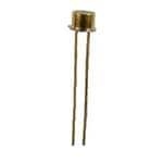
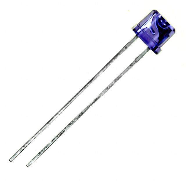
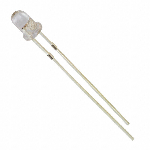
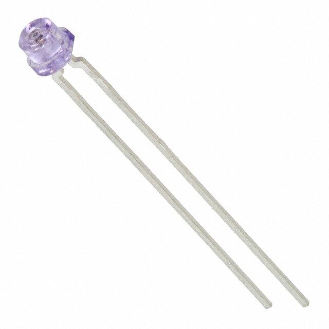
ICGOO电子元器件商城为您提供OP232W由OPTEK设计生产,在icgoo商城现货销售,并且可以通过原厂、代理商等渠道进行代购。 OP232W价格参考。OPTEKOP232W封装/规格:红外,UV,可见光发射器, Infrared (IR) Emitter 890nm 2V 100mA 50° TO-46-2 Metal Can。您可以下载OP232W参考资料、Datasheet数据手册功能说明书,资料中有OP232W 详细功能的应用电路图电压和使用方法及教程。
OP232W是TT Electronics/Optek Technology生产的一款红外发射器,广泛应用于需要红外光发射的电子设备中。其主要应用场景包括:

1. 红外遥控:常用于电视机、空调、音响等家用电器的遥控器中,作为红外信号发射元件,实现远程控制功能。

2. 传感与检测:在自动门、洗手间自动冲水系统、自动干手机等设备中,作为红外发射部分,与红外接收器配合使用,实现物体检测或距离感应。

3. 安防系统:用于红外报警系统或闭路监控系统中的红外补光,提升夜间监控效果。

4. 工业控制:在工业自动化设备中,用于非接触式信号传输或位置检测。

5. 通信设备:在短距离红外通信设备中,作为数据传输的光源。

OP232W具备良好的光效、稳定性和较长的使用寿命,适合多种中低功率红外发射应用场合。
| 参数 | 数值 |
| 产品目录 | |
| 描述 | DIODE IR HERMTC GAAIAS FLAT TO46红外发射源 Infrared 890nm |
| 产品分类 | |
| 品牌 | TT Electronics/Optek Technology |
| 产品手册 | |
| 产品图片 |
|
| rohs | 符合RoHS无铅 / 符合限制有害物质指令(RoHS)规范要求 |
| 产品系列 | 红外发射源,Optek / TT Electronics OP232W- |
| 数据手册 | |
| 产品型号 | OP232W |
| 上升时间 | 500 ns |
| 下降时间 | 250 ns |
| 不同If时的辐射强度(Ie)(最小值) | - |
| 产品培训模块 | http://www.digikey.cn/PTM/IndividualPTM.page?site=cn&lang=zhs&ptm=12167 |
| 产品种类 | 红外发射源 |
| 其它名称 | 365-1584 |
| 功率额定值 | 200 mW |
| 包装 | 散装 |
| 商标 | Optek / TT Electronics |
| 安装类型 | 通孔 |
| 安装风格 | Through Hole |
| 封装 | Bulk |
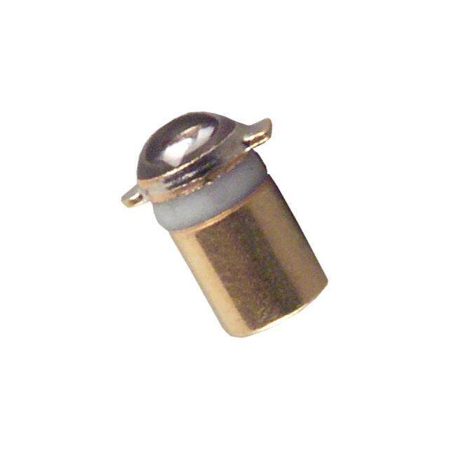
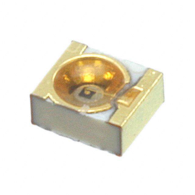
| 封装/外壳 | TO-46-2,金属罐 |
| 射束角 | 50 deg |
| 工厂包装数量 | 25 |
| 最大工作温度 | + 125 C |
| 最小工作温度 | - 65 C |
| 朝向 | 顶视图 |
| 标准包装 | 25 |
| 正向电压 | 2 V |
| 正向电流 | 100 mA |
| 波长 | 890nm |
| 照明颜色 | Infrared |
| 电压-正向(Vf)(典型值) | 2V |
| 电流-DC正向(If) | 100mA |
| 视角 | 50° |
| 辐射强度 | 8 mW |
| 透镜形状 | Flat |


PDF Datasheet 数据手册内容提取
Hermetic Infrared Emitting Diode OP230 Series Features: Focused and non‐focused op(cid:415)cal light pa(cid:425)ern Enhanced temperature range TO‐46 herme(cid:415)cally sealed package Mechanically and spectrally matched to other Optek devices Choice of power ranges Choice of narrow or wide irradiance pa(cid:425)ern Descrip(cid:415)on: Each device in this series is a gallium aluminum arsenide (GaAIAs) infrared emi(cid:427)ng diode, mounted in a herme(cid:415)c metal TO‐ 46 housing. The gallium aluminum arsenide feature provides a higher radiated output than gallium arsenide at the same forward current. Each OP231, OP232, OP233, OP234 and OP235 device is lensed to provide a narrow beam angle (18°) between half power points. The 890 nm wavelength closely matches the spectral response of silicon phototransistors, while the narrow beam angle – combined with the specified radiant intensity of the OP231 series – facilitates easy design in beam interrupt applica(cid:415)ons in conjunc(cid:415)on with the OP800 or OP598 series photosensors. The OP231 series is mechanically and spectrally matched to OP800, OP593 and OP598 phototransistors. Each OP231W, OP232W, OP233W, OP234W and OP235W device is lensed to provide a wide beam angle (50°) between half power points. The 890 nm wavelength closely matches the spectral response of silicon photo‐transistors, while the wide beam angle provides rela(cid:415)vely even illumina(cid:415)on over a large area. The OP231W is mechanically and spectrally matched to the OP800WSL and OP830SL series devices. Please refer to Applica(cid:415)on Bulle(cid:415)ns 208 and 210 for addi(cid:415)onal design informa(cid:415)on and reliability (degrada(cid:415)on) data. Custom electrical, wire and cabling and connectors are Ordering Informa(cid:415)on available. Contact your local representa(cid:415)ve or OPTEK for Output Power more informa(cid:415)on. Part LED Peak (mW/cm2) Total Beam Lead Number Wavelength Min / Max Angle Length OP231 1.5 / NA Applica(cid:415)ons: OP232 890 nm 2.0 / 6.0 Non‐contact reflec(cid:415)ve object sensor OP233 3.0 / NA 18° Assembly line automa(cid:415)on OP234 5.0 / NA 850 nm Machine automa(cid:415)on OP235 6.0 / NA 0.50" Machine safety OP231W 1.5 / NA OP232W 890 nm 3.5 / 7.0 End of travel sensor OP233W 5.0 / NA 50° Door sensor OP234W 5.0 / NA 850 nm OP235W 6.0 / NA General Note OPTEK Technology, Inc. TT Electronics reserves the right to make changes in product specification without notice or 1645 Wallace Drive, Carrollton, TX 75006|Ph: +1 972 323 2200 liability. All information is subject to TT Electronics’ own data and is considered accurate at www.optekinc.com | www.ttelectronics.com time of going to print. © TT electronics plc Issue B 07/2016 Page 1
Hermetic Infrared Emitting Diode OP230 Series OP231, OP232, OP233, OP234, OP235 Anode Cathode DIMENSIONS ARE IN: [MILLIMETERS] INCHES OP231W, OP232W, OP233W, OP234W, OP235W Anode Cathode Pin # LED 1 Anode DIMENSIONS ARE IN: [MILLIMETERS] 2 Cathode INCHES Absolute Maximum Ratings (T =25°C unless otherwise noted) A Storage Temperature Range ‐65o C to +150o C Operating Temperature Range ‐65o C to +125o C Reverse Voltage 2.0 A Continuous Forward Current 100 mA Peak Forward Current 10.0 A Lead Soldering Temperature [1/16 inch (1.6 mm) from case for 5 seconds with soldering iron] 260° C(1)(2) Power Dissipation 200 mW(3) General Note OPTEK Technology, Inc. TT Electronics reserves the right to make changes in product specification without notice or 1645 Wallace Drive, Carrollton, TX 75006|Ph: +1 972 323 2200 liability. All information is subject to TT Electronics’ own data and is considered accurate at www.optekinc.com | www.ttelectronics.com time of going to print. © TT electronics plc Issue B 07/2016 Page 2
Hermetic Infrared Emitting Diode OP230 Series Electrical Characteris(cid:415)cs (T = 25°C unless otherwise noted) A SYMBOL PARAMETER MIN TYP MAX UNITS TEST CONDITIONS Input Diode Apertured Radiant Incidence OP231 1.5 ‐ ‐ OP231 Series OP232 2.0 ‐ 6.0 mW/ I = 100 mA(3 )(4) F OP233 3.0 ‐ ‐ cm2 Aperture = 0.250” OP234 5.0 ‐ ‐ Distance = 1.429” OP235 6.0 ‐ ‐ E E(APTa) OP231W 1.5 ‐ ‐ OP231W Series OP232W 3.5 ‐ 7.0 mW/ I = 100 mA(3 )(4) OP233W 5.0 ‐ ‐ F cm2 Aperture = 0.250” OP234W 5.0 ‐ ‐ Distance = 0.466” OP235W 6.0 ‐ ‐ Radiant Power Output OP231 ‐ 6.0 ‐ P I = 100 mA(3 )(4) O OP232 ‐ 8.0 ‐ mW F OP233 ‐ 10.0 ‐ V Forward Voltage ‐ ‐ 2.0 V I = 100 mA (3) F F I Reverse Current ‐ ‐ 100 µA V = 2.0 V R R Wavelength at Peak Emission λ OP231, OP232, OP233 ‐ 890 ‐ P nm I = 10 mA OP234, OP235 ‐ 850 ‐ F Spectral Bandwidth between Half Power β ‐ 80 ‐ nm I = 10 mA Points F ∆λ /∆T Spectral Shi(cid:332) with Temperature ‐ +0.30 ‐ nm/°C I = Constant P F Emission Angle at Half Power Points θ OP231 ‐ OP235 ‐ 18 ‐ HP Degree I = 100 mA OP231W ‐ OP231W ‐ 50 ‐ F t Output Rise Time ‐ 500 ‐ ns r I =100 mA, PW=10 µs, and F(PK) t Output Fall Time ‐ 250 ‐ ns D.C.=10.0% f Notes: 1. RMA flux is recommended. Dura(cid:415)on can be extended to 10 seconds maximum when flow soldering. 2. Derate linearly 2.0 mW/° C above 25° C. 3. Measurement made with 100 µs pulse measured at the trailing edge of the pulse with a duty cycle of 0.1% and an I = 100 mA. F 4. For the OP231 series, E is a measurement of the average radiant intensity within the cone formed by the measurement surface, a radius of E(APT) 1.429” (36.30 mm) measured from the lens side of the tab to the sensing surface and a sensing surface of 0.250” (6.35 mm) in diameter forming a 10° cone. For the OP231W series, E is a measurement of the average radiant intensity within the cone formed by the measurement surface, a radius E(APT) of 0.466” (11.84 mm) measured from the lens side of the tab to the sensing surface and a sensing surface of 0.250” (6.35 mm) in diameter forming a 10° cone. E is not necessarily uniform within the measured area. E(APT) General Note OPTEK Technology, Inc. TT Electronics reserves the right to make changes in product specification without notice or 1645 Wallace Drive, Carrollton, TX 75006|Ph: +1 972 323 2200 liability. All information is subject to TT Electronics’ own data and is considered accurate at www.optekinc.com | www.ttelectronics.com time of going to print. © TT electronics plc Issue B 07/2016 Page 3
Hermetic Infrared Emitting Diode OP230 Series OP231, OP232, OP233 (including “W” devices) Forward Voltage vs Forward Current vs Temperature Optical Power vs I vs Temperature F 1.8 3.5 Normalized at 50 mA and 20° C 1.7 3.0 -60° C -40° C 1.6 -20° C e (V) 1.5 wer 2.5 024°00 °°C CC g o 60° C olta al P 2.0 81000° °C C d V 1.4 ptic 120° C ar O orw 1.3 zed 1.5 ypical F 1.2 ---0642°000 C°°° CCC Normali 1.0 T 20° C 1.1 40° C 60° C 0.5 80° C 1.0 100° C 120°C 0.9 0.0 0 10 20 30 40 50 60 70 80 90 100 0 10 20 30 40 50 60 70 80 90 100 Forward Current (mA) Forward Current IF (mA) Relative Radiant Intensity vs. Angular Distance vs Output Power vs Forward Current Displacement 6 1.0 Normalized at 1" and 50 mA 0.9 5 0.8 Forward Current 10 mA wer 4 2300 mmAA sity 0.7 o n ormalized Output P 23 45678910000000 0mmmmmm mAAAAAAA Relative Radiant Inte 0000....3456 N 0.2 1 0.1 0 0.0 0.2 '' 0.4 '' 0.6 '' 0.8 '' 1.0 '' 1.2 '' 1.4 '' 1.6 '' 1.8 '' 2.0 '' -20 -15 -10 -5 0 5 10 15 20 Distance (inches) Angular Displacement (Degrees) General Note OPTEK Technology, Inc. TT Electronics reserves the right to make changes in product specification without notice or 1645 Wallace Drive, Carrollton, TX 75006|Ph: +1 972 323 2200 liability. All information is subject to TT Electronics’ own data and is considered accurate at www.optekinc.com | www.ttelectronics.com time of going to print. © TT electronics plc Issue B 07/2016 Page 4
Hermetic Infrared Emitting Diode OP230 Series OP234, OP234W Forward Voltage vs Forward Current vs Optical Power vs Forward Current vs Temperature Temperature 1.8 2.5 Normalized at 50 mA and 20°C 1.6 -60° C 2.0 -40° C -20° C V) 0° C ge ( 1.4 wer 2400°° CC d Volta put Po 1.5 6810000°° °CC C ar 1.2 ut 120° C w O or e F -60° C v 1.0 al -40° C ati ypic 1.0 -02°0 C° C Rel T 20° C 40° C 0.5 0.8 60° C 80° C 100° C 120° C 0.6 0.0 0 5 10 15 20 25 30 35 40 45 50 0 10 20 30 40 50 60 70 80 90 100 Forward Current (mA) Forward Current I (mA) F Relative Radiant Intensity vs Angular Distance vs Output Power vs Forward Current Displacement 10.00 1.2 Normalized at 1.0" and 50 mA 1.0 wer1.00 sity 0.8 o n P e Output diant Int 0.6 d Ra ormalize0.10 Forward 123C000u rmmmreAAAnt Relative 0.4 N 40 mA 50 mA 60 mA 0.2 80 mA 100 mA 120 mA 0.0 0.01 -80 -30 20 70 0.2 '' 0.7 '' 1.2 '' 1.7 '' Angular Displacement (Degrees) Distance (inches) General Note OPTEK Technology, Inc. TT Electronics reserves the right to make changes in product specification without notice or 1645 Wallace Drive, Carrollton, TX 75006|Ph: +1 972 323 2200 liability. All information is subject to TT Electronics’ own data and is considered accurate at www.optekinc.com | www.ttelectronics.com time of going to print. © TT electronics plc Issue B 07/2016 Page 5
Hermetic Infrared Emitting Diode OP230 Series OP235, OP235W Forward Voltage vs Forward Current vs Optical Power vs Forward Current vs Temperature Temperature 1.8 2.5 Normalized at 50 mA and 20° C 1.6 -60°C 2.0 -40°C -20°C V) 0°C e ( 1.4 er 2400°°CC d Voltag put Pow 1.5 6811020000°°CC°°CC ar 1.2 ut w O or e al F --6400°°CC ativ 1.0 pic 1.0 -20°C Rel y 0°C T 20°C 40°C 0.5 0.8 60°C 80°C 100°C 120°C 0.6 0.0 0 5 10 15 20 25 30 35 40 45 50 0 10 20 30 40 50 60 70 80 90 100 Forward Current (mA) Forward Current I (mA) F Distance vs Output Power vs Forward Current 20 Normalized at 1.0" and 50 mA 18 Forward Current 16 10 mA wer 14 2300 mmAA o 40 mA P put 12 5600 mmAA Out 10 8100 0m mAA d 120 mA e aliz 8 m or 6 N 4 2 0 0.2 '' 0.4 '' 0.6 '' 0.8 '' 1.0 '' 1.2 '' 1.4 '' 1.6 '' 1.8 '' 2.0 '' Distance (inches) General Note OPTEK Technology, Inc. TT Electronics reserves the right to make changes in product specification without notice or 1645 Wallace Drive, Carrollton, TX 75006|Ph: +1 972 323 2200 liability. All information is subject to TT Electronics’ own data and is considered accurate at www.optekinc.com | www.ttelectronics.com time of going to print. © TT electronics plc Issue B 07/2016 Page 6
Mouser Electronics Authorized Distributor Click to View Pricing, Inventory, Delivery & Lifecycle Information: T T Electronics: OP231 OP231W OP232 OP232W OP233 OP233W OP234 OP234W OP235 OP235W